

Page 1
Programmable Device Server
(For PDS(M)-700, PPDS(M)-700-MTCP, DS-700, PPDS-700-IP67)
User Manual
Programmable Device Server New Features
1. Virtual COM Technology
2. Virtual I/O Technology
3. Web-server Technology
4. MiniOS7 & Xserver Inside
5. Programmable Solution
6. Industrial PoE Solution
7. Modbus/TCP to Modbus/RTU Gateway
Your Powerful Tools
Create New Ideas
Create New Applications
Warranty
All products manufactured by ICP DAS are under warranty regarding defective materials for a
period of one year, starting from the date of delivery to the original purchaser.
Warning
ICP DAS assumes no liability for damages resulting from the use of this product. ICP DAS
reserves the right to change this manual at any time without notice. The information furnished
by ICP DAS is believed to be accurate and reliable. However, no responsibility is assumed by
ICP DAS for its use, nor for any infringements of patents or other rights of third parties
resulting from its use.
Copyright
Copyright 2008 by ICP DAS. All rights are reserved.
Trademark
The names used for identification only may be registered trademarks of their respective
companies.
PDS Series User Manual ( V1.4, Oct. 2009) ----- 1
Page 2

Table of Contents
1. INTRODUCTION 6
1.1.
W
HY ETHERNET SOLUTIONS
1.2.
W
HY VXCOMM TECHNOLOGY
1.3.
W
HY WEB SERVER TECHNOLOGY
2. TYPICAL APPLICATIONS FOR THE PDS 11
2.1. RS-232/485/422 D
2.2.
E
THERNET
2.3.
L
INKING
2.4.
C
ONFIGURABLE ETHERNET DATA LOGGER
3. HARDWARE INFORMATION 16
3.1.
F
EATURES
3.2.
S
PECIFICATIONS
3.3.
PDS C
3.4.
P
IN ASSIGNMENTS
3.5.
PDS W
I-7000 S
16
OMPARISON TABLE
IRING CONNECTIONS
EVICE NETWORKING
I/O A
PPLICATIONS
ERIES MODULES TO AN ETHERNET NETWORK
17
29
? 7
? 8
? 10
11
12
13
13
25
63
3.6.
D
IMENSIONS AND MOUNTING
3.7.
PDS
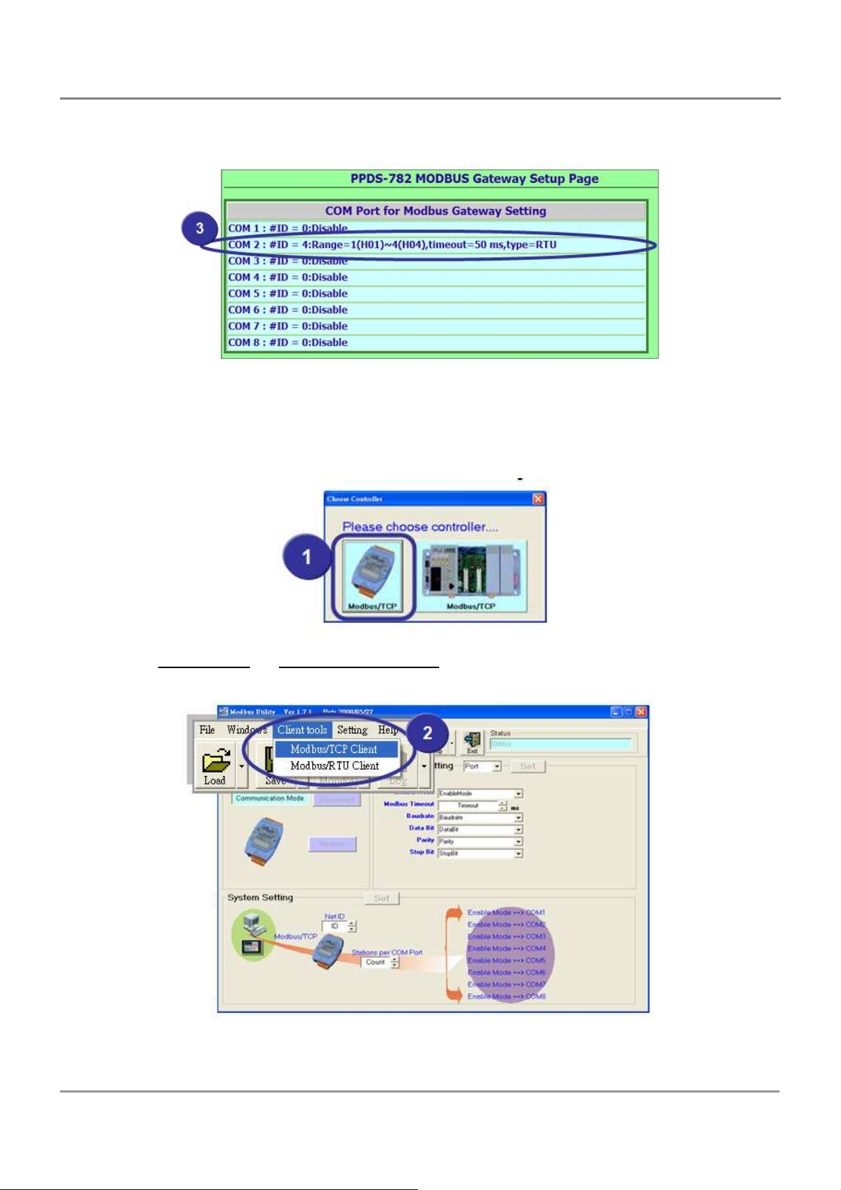
SERIES DIAGNOSTICS
4. SETTING UP THE PDS MODULE 74
5. CONFIGURATION WITH WEB BROWSER 81
5.1.
C
ONNECTING TO THE
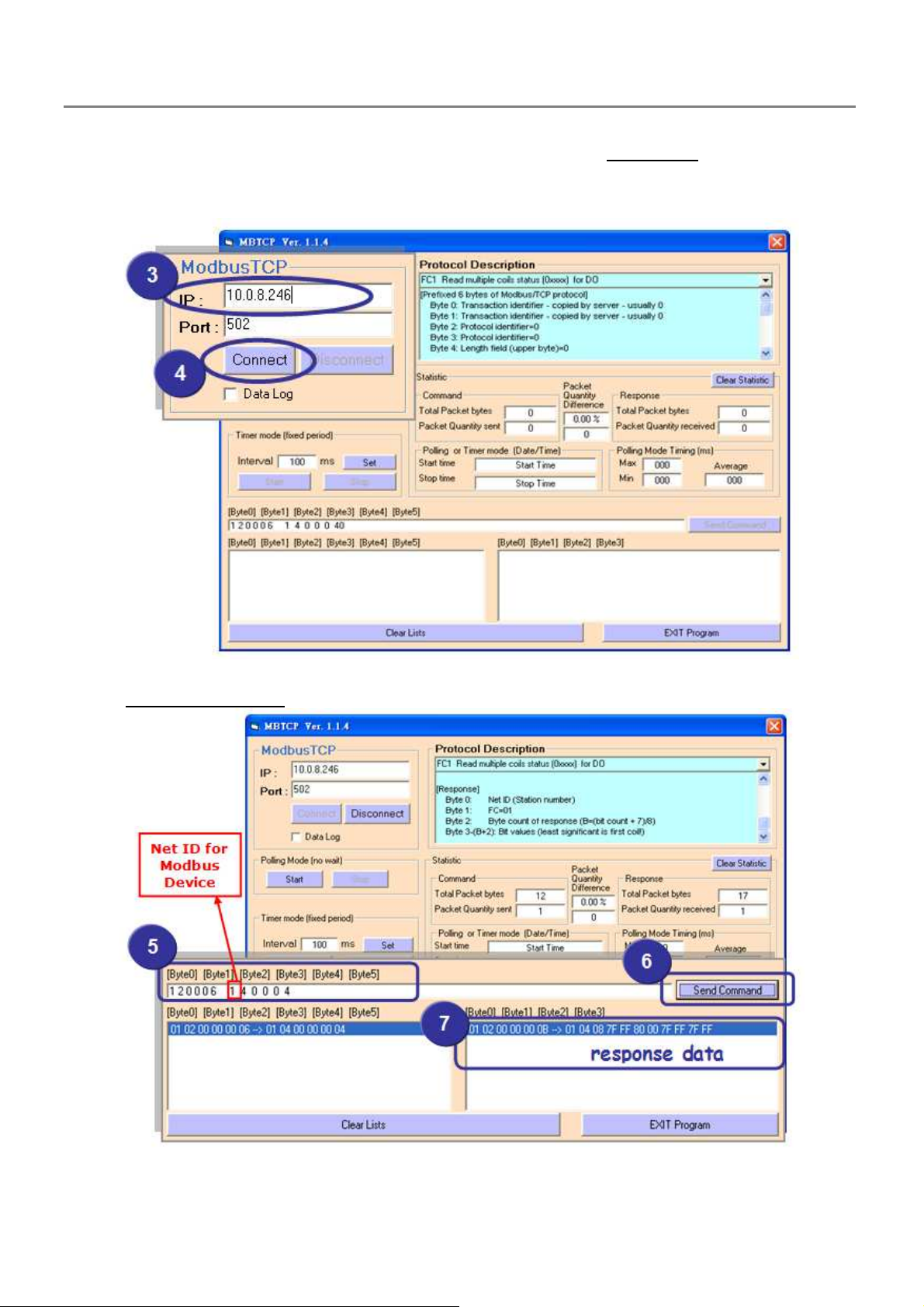
5.2.
N
ETWORK SETTINGS
5.3.
IP
FILTER SETTING
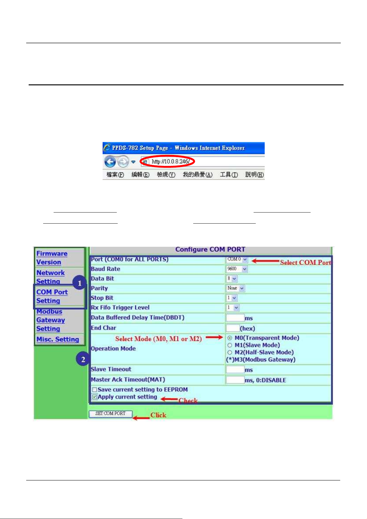
5.4.
COM P
5.5.
P
5.6.
M
6. MODBUS TESTING & PROTOCOL 96
6.1.
M
6.2.
T
7. VIRTUAL I/O 103
ORT SETTINGS
AIR CONNECTION SETTING
ISCELLANEOUS SETTINGS
ODBUS
/TCP
TO MODBUS
ESTING MODBUS DEVICE THROUGH VIRTUAL
PDS S
82
85
65
70
ERIES MODULE
86
? 92
94
/RTU G
ATEWAY
81
97
COM P
ORTS
100
7.1.
7.2.
T
ESTING THE VIRTUAL
V
IRTUAL
I/O C
OMMANDS TEST
I/O 103
107
PDS Series User Manual ( V1.4, Oct. 2009) ----- 2
Page 3

7.3.
P
ROGRAMMING ON A PC CLIENT
109
8. VIRTUAL I/O COMMANDS 117
8.1.
$AA5 119
8.2.
$AA6 120
8.3.
$AAC 121
8.4.
$AACN 122
8.5.
$AAGCN 123
8.6.
$AALS 124
8.7.
$AAF 125
8.8.
$AAM 126
8.9.
@AA 127
8.10. @AA(D
8.11. #AAN 129
8.12. #AA00DD 130
8.13. #AA1
8.14. ~** 132
8.15. ~AA0 133
ATA
) 128
NDD
131
8.16. ~AA1 134
8.17. ~AA2 135
8.18. ~AA3
8.19. ~AA4P 138
8.20. ~AA4S 139
8.21. ~AA5P 140
8.22. ~AA5S 141
8.23. A
9. CONSOLE / TELNET COMMANDS LIST 145
9.1.
9.2.
9.3.
9.4.
APPENDIX A: LINKING TO A DEVELOPMENT PC 172
APPENDIX B: FRAME GROUND 175
EFF
136
PPLICATION NOTES
O
PERATION FLOWCHART
R
EGULATE INIT/NORMAL MODE
C
OMPARISON SHEET (INIT/RUN/CONSOLE MODES
C
OMMAND LIST
142
145
146
150
) 149
GLOSSARY 177
1. E
2. I
THERNET
NTERNET
177
177
PDS Series User Manual ( V1.4, Oct. 2009) ----- 3
Page 4

3. TCP/IP 177
4. TCP (T
5. UDP (U
6. G
7. IP (I
8. MAC (M
9. S
10.
11.
12.
13.
14.
15.
16.
17.
FAQ 181
RANSMISSION CONTROL PROTOCOL
SER DATAGRAM PROTOCOL
ATEWAY
UBNET MASK
ARP (A
RARP (R
ICMP (I
P
P
S
C
F
177
NTERNET PROTOCOL) ADDRESS
EDIA ACCESS CONTROL) ADDRESS
178
DDRESS RESOLUTION PROTOCOL
EVERSE ADDRESS RESOLUTION PROTOCOL
NTERNET CONTROL MESSAGES PROTOCOL
ING
179
ACKET
179
OCKET
179
LIENTS AND SERVERS
IRMWARE
180
180
) 177
178
) 177
178
) 178
) 179
) 179
1. H
2. H
3. D
4. D
5. W
6. D
DEVICE SERVERS
7. W
8. C
PORT
9. H
10.
SOLVE IT
OW TO ACCESS THE REMOTE
OW TO OPEN A VIRTUAL
OES VXCOMM DRIVER
OES VXCOMM DRIVER
HY DOESN'T THE VXCOMM DRIVER
OES THE TRANSMISSION SPEED BECOME FASTER WHEN THE SERIAL DEVICE WORKING WITH SERIAL TO ETHERNET
HY DOES THE
AN I USE THE SETCOMMSTATE ( )
? 189
OW MANY PCS CAN BE CONNECTED TO A SINGLE
C
? 191
PDS
THAT PLACED BEHIND AN
COM
PORT THAT LARGER THAN
(PC) V2.00
(PC)
WORK WITH VXCOMM SERVER V
SUPPORT AUTO-RECONNECTION AFTER FIXING A NETWORK BREAK
(PC)
RECEIVE DATA FROM THE
NAT
"COM 9"
OR FIREWALL
BY CALLING CREATEFILE() WIN32
? 181
API? 182
2.6.00? 183
? 183
PDS
SERIES MODULE
? 184
? 185
PDS
SERIES MODULE FAIL ON A (PUBLIC) INTERNET CONNECTION
AN I SEARCH OR CONNECT TO
API
TO CHANGES THE BAUD RATE/DATA FORMAT SETTINGS OF A VIRTUAL
PDS
PDS
WHEN MY
DEVICE
PC’S IP
? 189
ADDRESS IS NOT IN THE IP FILTER LIST OF
? 187
PDS? H
COM
OW CAN I
PDS Series User Manual ( V1.4, Oct. 2009) ----- 4
Page 5

1.
3.
Packing List
The package includes the following items:
One (Programmable) Device Server hardware module
One companion DVD
One RS-232 download cable, CA-0910
(Only for
PDS(M)-700(D), PPDS(M)-700(D)-MTCP
)
One Quick Start Guide
2.
4.
Quick Start
Note:
If any of these items are missed or damaged, contact the local distributors for more
information. Save the shipping materials and cartons in case you want to ship in the future.
More Information:
Documentations
CD: Napdos\PDS\PDS-700\Document
http://ftp.icpdas.com/pub/cd/8000cd/napdos/pds/pds-700/document/
VxComm Driver (Virtual COM)
CD: \NAPDOS\ Driver\VxComm_Driver
http://ftp.icpdas.com/pub/cd/8000cd/napdos/driver/vxcomm_driver/
Firmware
CD:\ Napdos\PDS\PDS-700\VxComm\Server(PDS)
http://ftp.icpdas.com/pub/cd/8000cd/napdos/pds/pds-700/vxcomm/server(pds)/
MiniOS7
CD:\NAPDOS\PDS\PDS-700\OS_image
http://ftp.icpdas.com/pub/cd/8000cd/napdos/pds/pds-700/os_image/
PDS Series User Manual ( V1.4, Oct. 2009) ----- 5
Page 6
1. Introduction
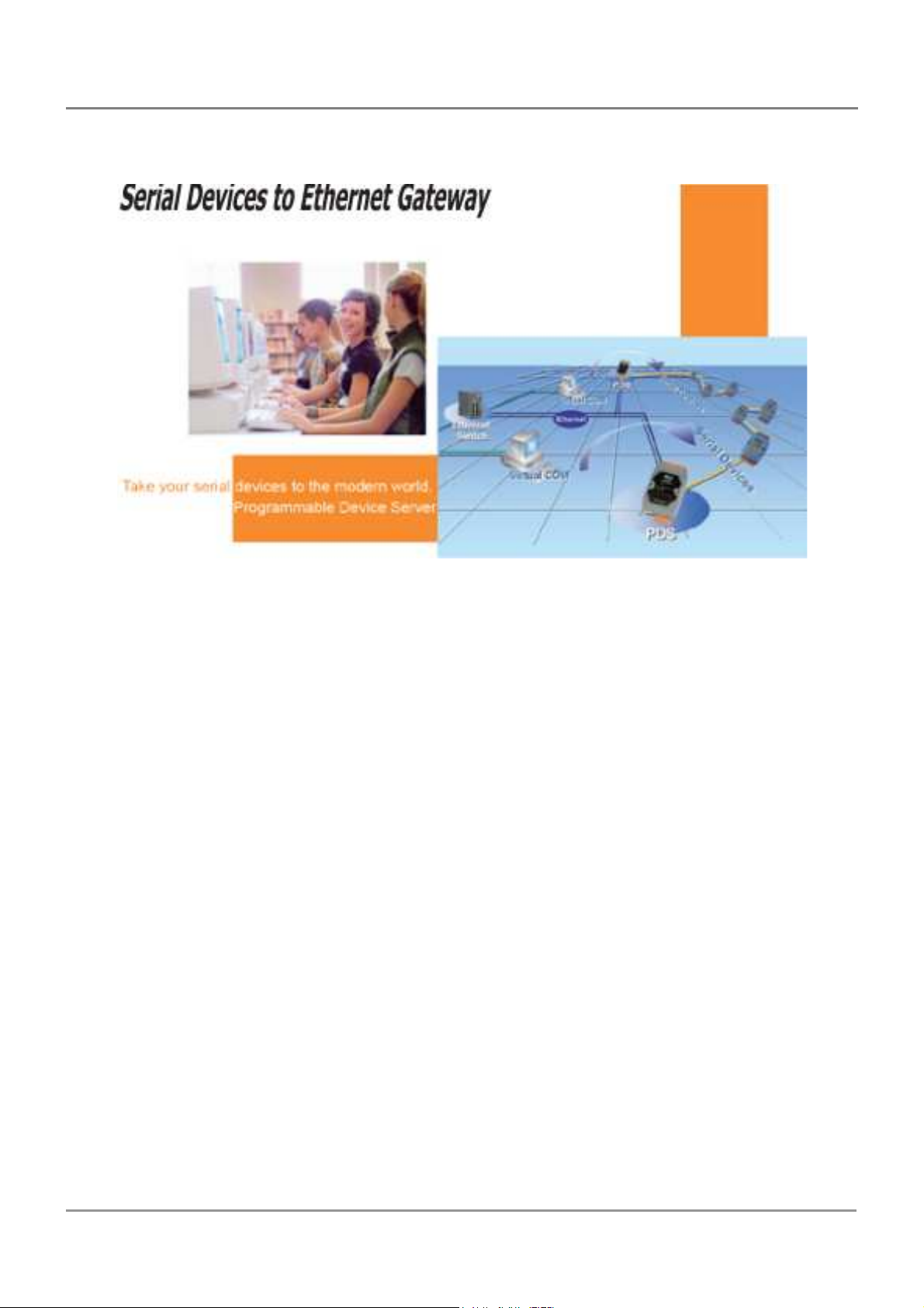
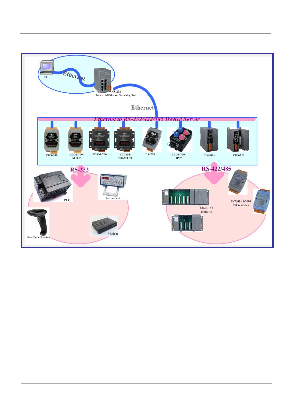
The PDS-700 series is a family of Programmable Device Servers, also known as
"Serial-to-Ethernet gateway", that are designed for linking RS-232/422/485 devices to
an Ethernet network. The user-friendly VxComm Driver/Utility allows users to easily
turn the built-in COM ports of the PDS-700 series into standard COM ports on a PC.
By virtue of its protocol independence, a small-core OS and high flexibility, the PDS700 series is able to meet the demands of every network-enabled application.
The PDS-700 series includes a powerful and reliable Xserver programming structure
that allows you to design your robust Ethernet applications in one day. The built-in,
high-performance MiniOS7 boots the PDS-700 up in just one second and gives you
fastest responses.
The PPDS-700-MTCP series features true IEEE 802.3af-compliant (classification,
Class 1) Power over Ethernet (PoE) using a standard category 5 Ethernet cable to
receive power from a PoE switch like the NS-205PSE. The PPDS-700-MTCP also
works as a Modbus/TCP to Modbus/RTU gateway that supports most SCADA/HMI
communications based on the Modbus/TCP protocol. The PDSM-700 is the PDS-700
with Metal Case (RoHS) and the PPDSM-700-MTCP is the PPDS-700-MTCP with
Metal Case (RoHS). Metal Case version includes stronger protection than PDS-700
and PPDS-700-MTCP.
PDS Series User Manual ( V1.4, Oct. 2009) ----- 6
Page 7
1.1. Why Ethernet Solutions?
Nowadays, the Ethernet protocol has become the de-facto standard for local area
networks. Via the Internet, connectivity is occurring everywhere, from home appliances, to
vending machines, to testing equipment, to UPS ...etc. An Ethernet network can link office
automation and industrial control networks, access remote systems and share data and
information between multivendor machines; it also provides a cost-effective solution for
industrial control networks.
PDS Series User Manual ( V1.4, Oct. 2009) ----- 7
Page 8
1.2. Why VxComm Technology?
In general, writing a TCP/IP program is more difficult than a COM port program, or the
COM port communication system was built many years ago.
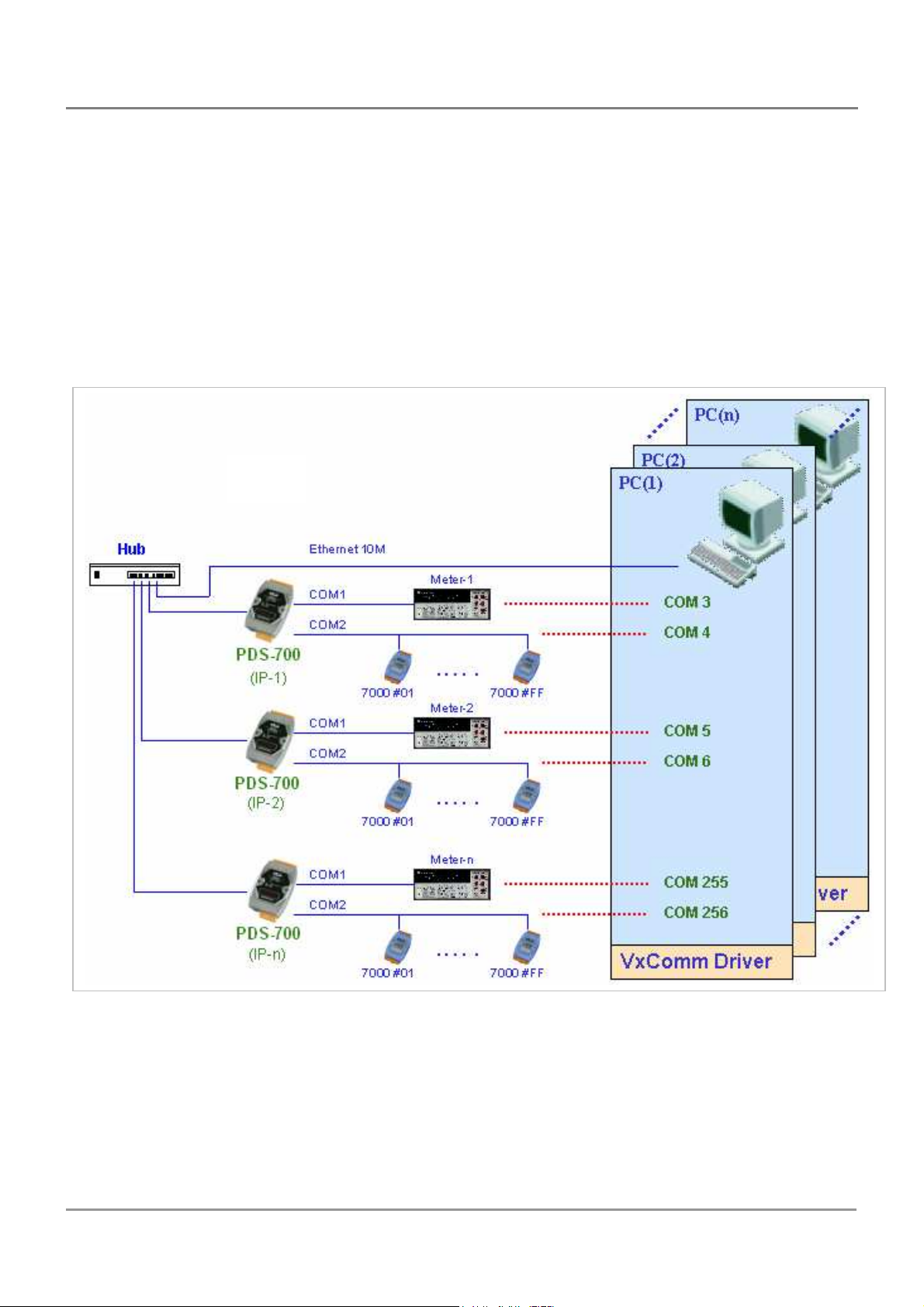
As a result, a new technology, VxComm was developed to virtualize the COM ports
of the PDS to allow up to 256 COM Ports to be used on the central computer. The
VxComm driver saves time when accessing serial devices through the Ethernet without the
need for reprogramming the COM port software on the PC.
PDS Series User Manual ( V1.4, Oct. 2009) ----- 8
Page 9
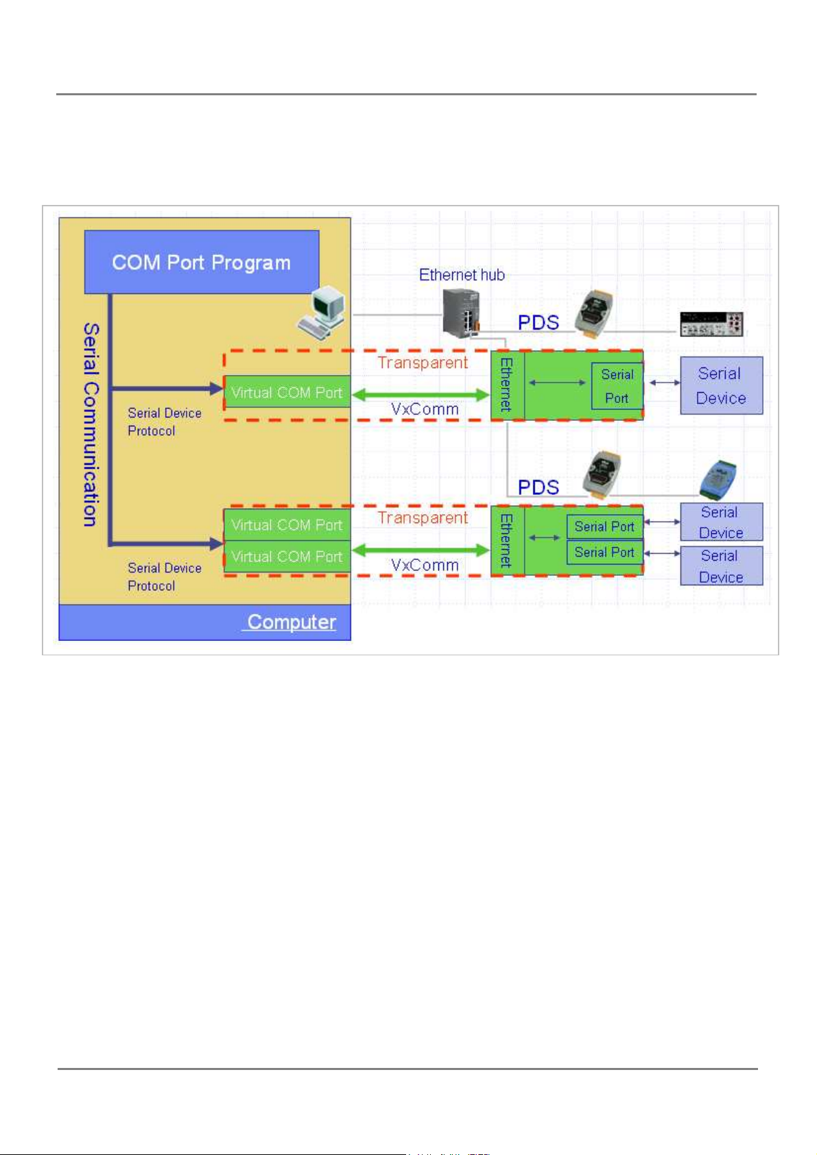
The VxComm driver controls all the details of the Ethernet TCP/IP programming
technique; your COM port program will be able to access your serial devices through
Ethernet in the same way as through COM port with the assistance of PDS and VxComm
technology.
PDS Series User Manual ( V1.4, Oct. 2009) ----- 9
Page 10
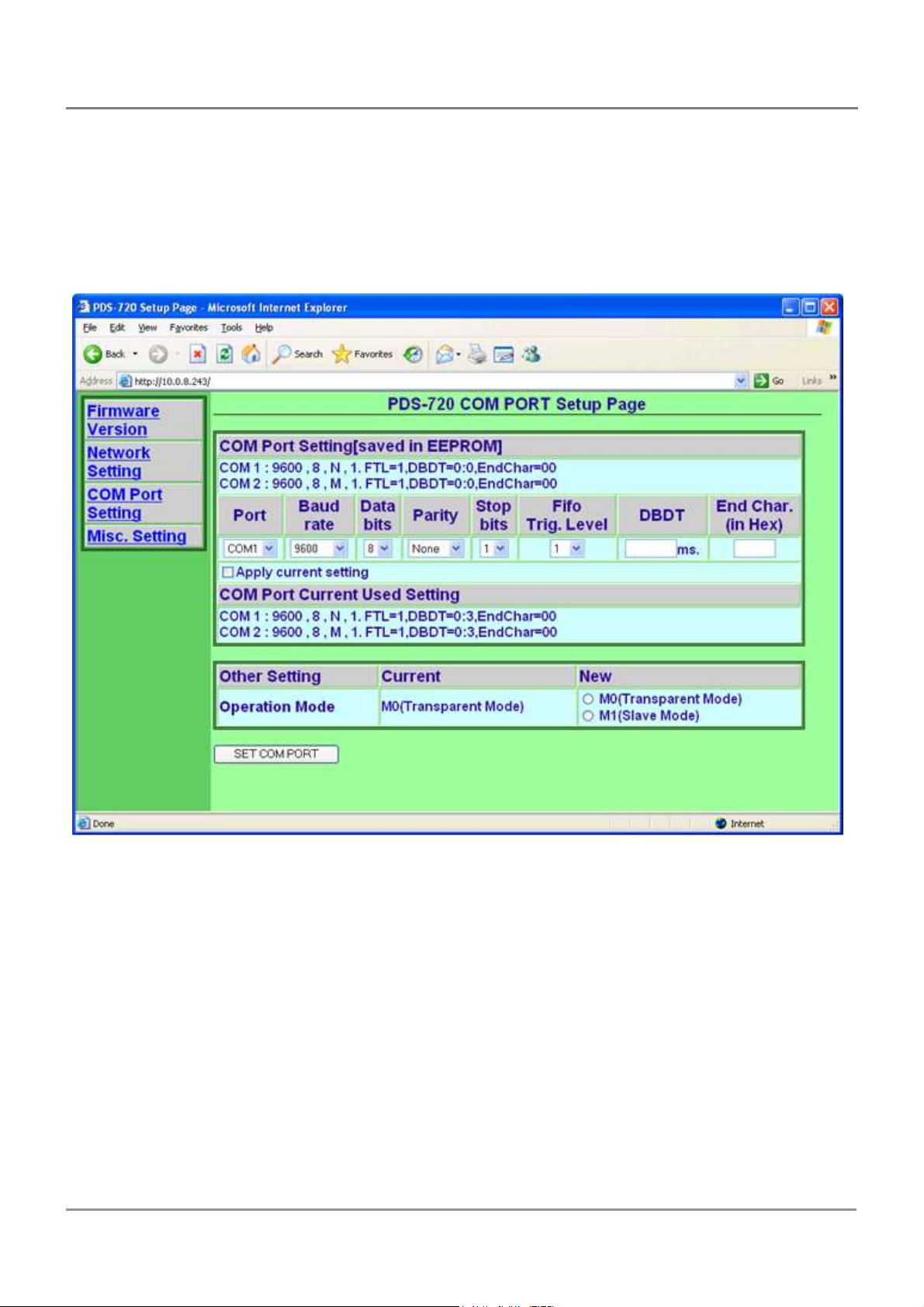
1.3. Why Web Server Technology?
Web server technology enables configuration of the PDS via a standard web browser
interface, e.g. Internet Explorer, FireFox or Mozilla, etc. This means that it is easy to
check the configuration of the PDS via an Ethernet network without needing to install any
other software tools; thereby reducing the user’s learning carve.
PDS Series User Manual ( V1.4, Oct. 2009) ----- 10
Page 11
COM3/4 of
the
host
PC
COM5/6 of
the
host
PC
2. Typical Applications for the PDS
2.1. RS-232/485/422 Device Networking
--- Using Virtual COM Technology ---
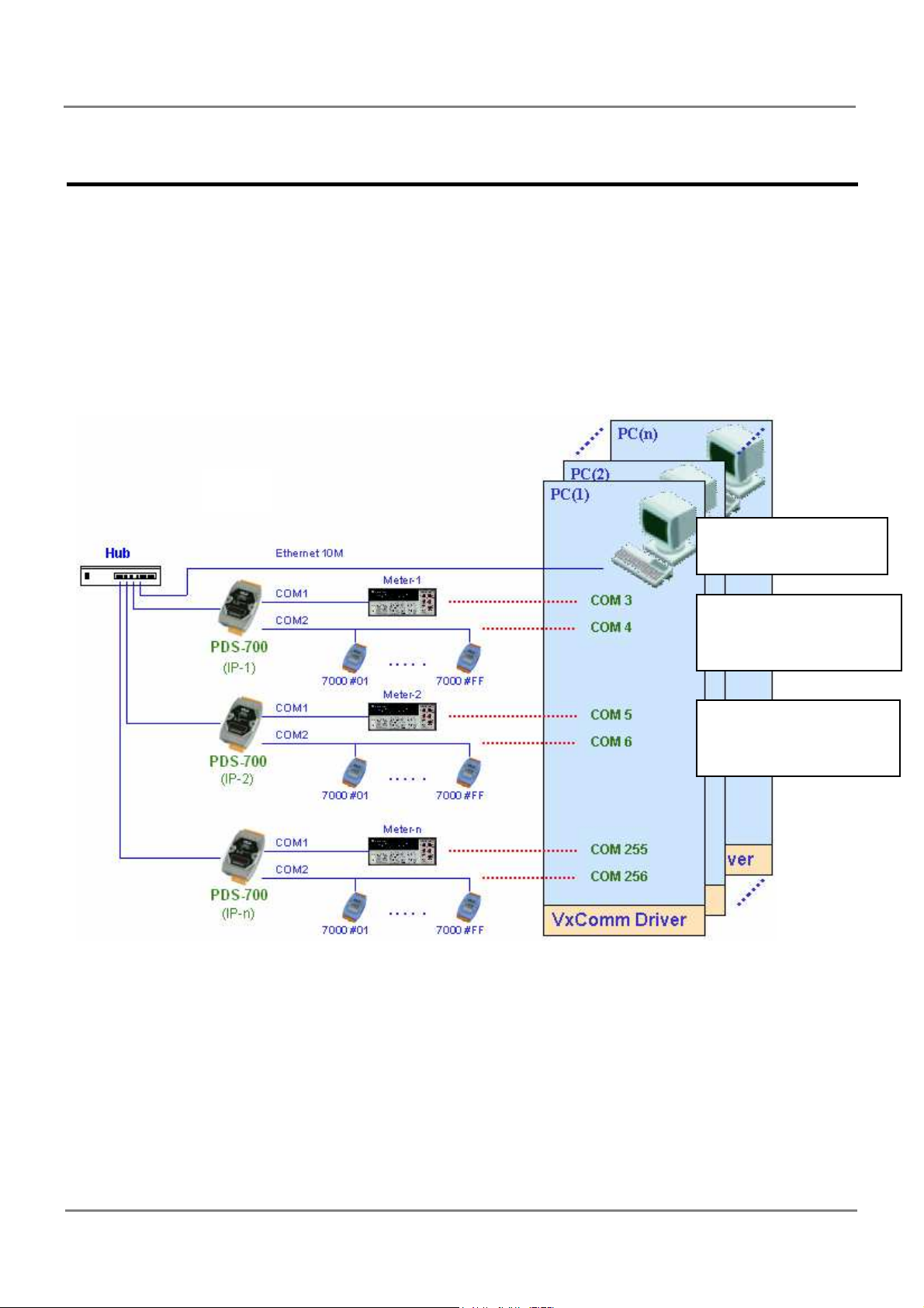
The PDS series is designed to link RS-232/485/422 devices to an Ethernet network. The
VxComm utility allows the built-in PDS COM Port to be virtualized to a standard COM
Port of the host PC as shown below:
The original COM1/2
of the host PC
COM1/2 of the PDS-
700 is mapped to
COM1/2 of the PDS-
700 is mapped to
In the configuration above, Meter-1 is virtualized to link to COM3 of the host PC.
Therefore a program original designed for the MS-COMM standard can access the meter
without any modification.
PDS Series User Manual ( V1.4, Oct. 2009) ----- 11
Page 12
2.2. Ethernet I/O Applications
The PDS series provides 2 types of Ethernet I/O solutions:
1. Linking to I-7000 series modules
2. Built-in DIO (if the module supports the DIO function)
Linking to I-7000 series modules
The I-7000 series provides a variety of I/O operations, such as D/I, D/O, A/D, D/A,
Counter and Frequency Measurement, etc. The I-7000 series was originally designed to be
used with RS-485 networks, so COM2 on the PDS-700 can be used to link to I-7000 series
modules.
By using VxComm technology, programs that on the host PC support serial devices
can be upgraded from a RS-485 network to an Ethernet network without requiring any
modifications to the program. Refer to Sec. 2.1 for more information.
Built-in DIO
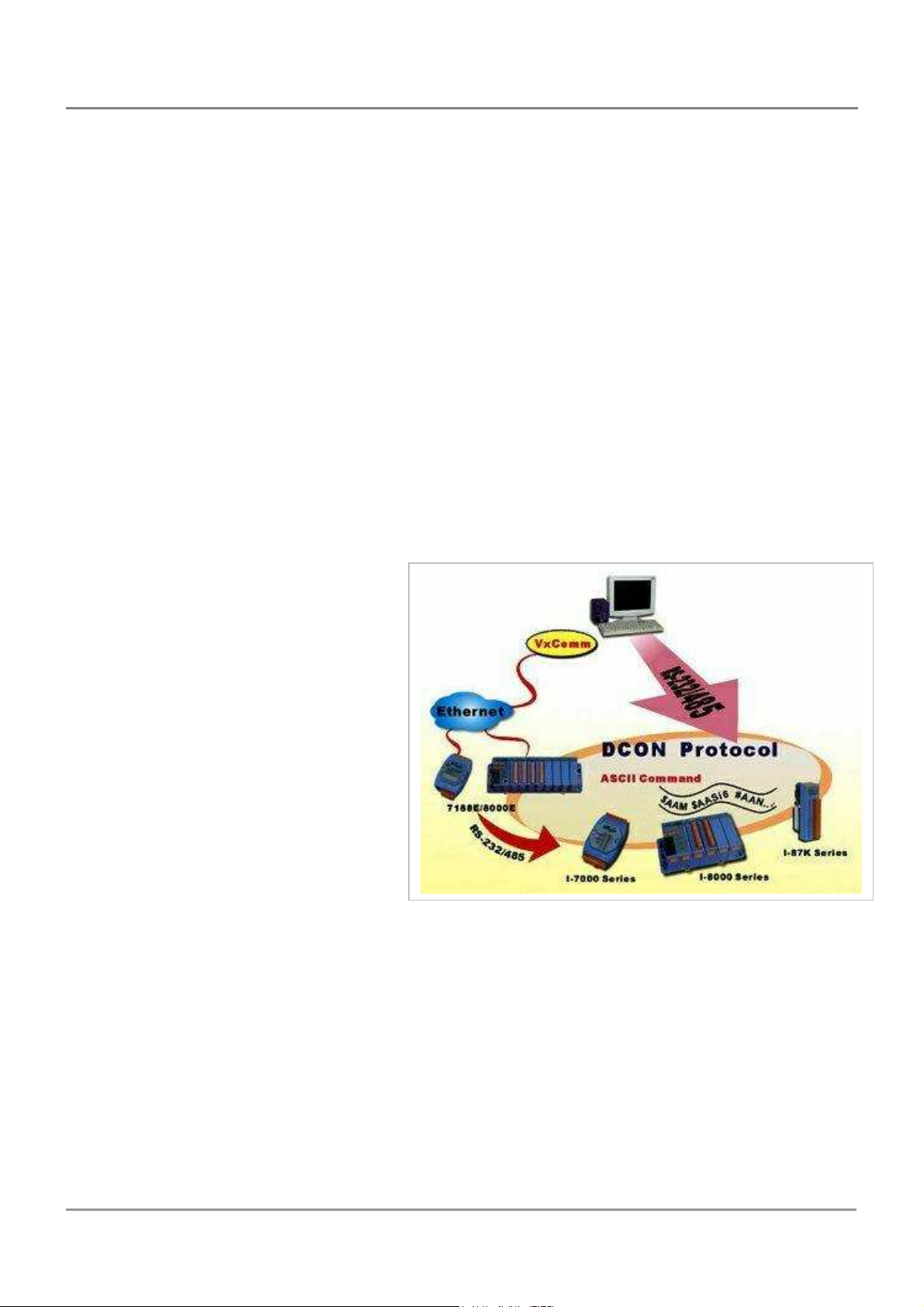
The DCON protocol is a request
/reply communication. Protocol that
is defined using a simple ASCII
format, such as $AAN, $AASi6,
#AAN, etc. and is used to access
PDS and I-7000/8000/ 87k series I/O
modules.
The DCON protocol command
set for the PDS is introduced in Sec.
7. The protocol allows access the
built-in I/O through the virtual COM Ports mapped to the Port I/O of the PDS in the
VxComm Utility.
PDS Series User Manual ( V1.4, Oct. 2009) ----- 12
Page 13
2.3. Linking I-7000 Series Modules to an Ethernet Network
The I-7000 family was originally designed for use with an RS-485 network. They are
very robust and work well under the harsh industrial environments.
The PDS enables I-7000 modules to be upgraded to an Ethernet solution. Linking I7000 modules to an Ethernet combines the advantages of both RS-485 and Ethernet
solutions and expands RS-485 applications to the whole world.
The VxComm approach provides an MS-COMM-compatible interface. Therefore,
previously developed programs should still function without the need for any
modifications.
2.4. Configurable Ethernet Data Logger
Using the VxComm driver, PDS + 7000 modules can be virtualized to become COM
Port + 7000 modules located on the host-PC, and then the Data Logger in the DCON
Utility can be used to access data of I-7000 from the Ethernet. Signal data originating from
the I-7000 modules can be analyzed using MS-Excel without the need to write any custom
programs
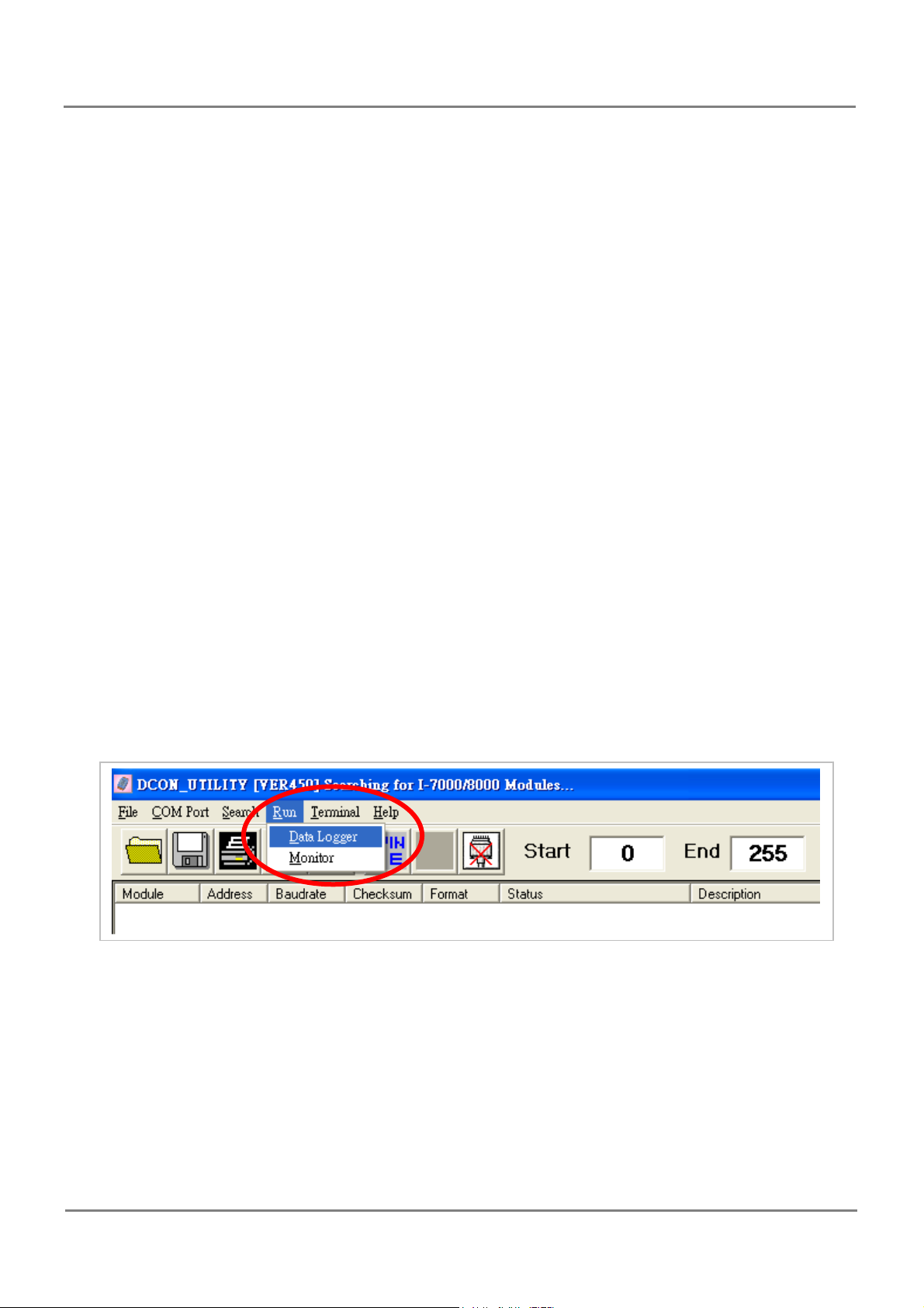
1: The DCON utility includes a log function, as show below:
PDS Series User Manual ( V1.4, Oct. 2009) ----- 13
Page 14
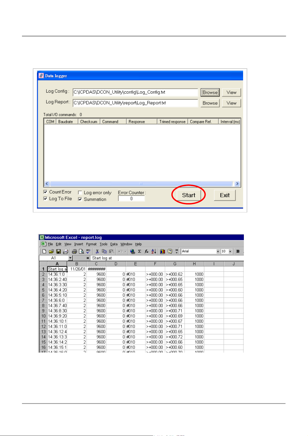
2: Configure the system connection as shown below and click the “Start” button to begin
logging data.
3: Open the log file in Excel to read the log data as shown in the example below:
PDS Series User Manual ( V1.4, Oct. 2009) ----- 14
Page 15
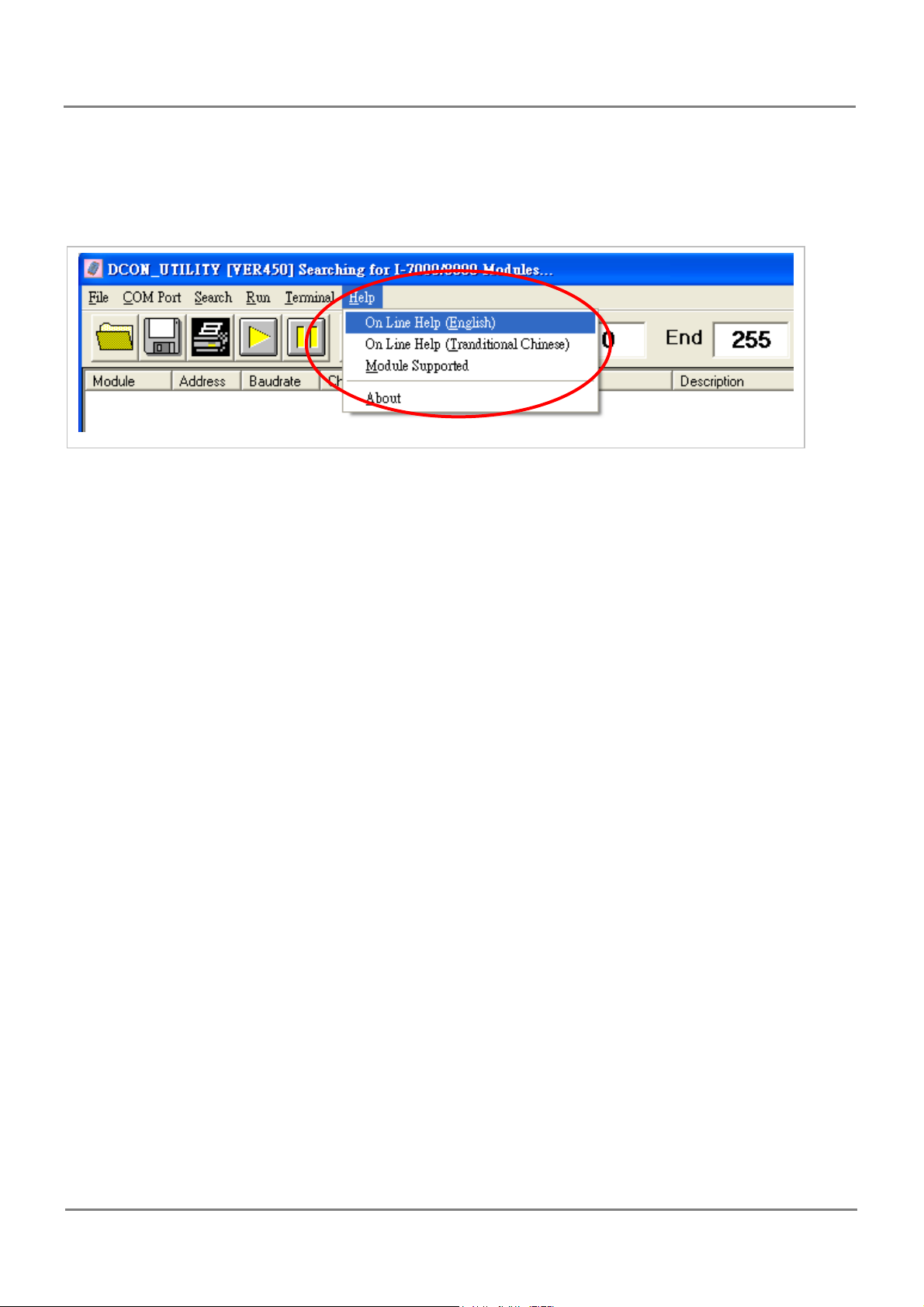
By using the I-7000 DCON utility and MS Excel in conjunction with the VxComm
technology, the signal data of I-7000 modules from the Ethernet network can be analyzed
without the need to write custom programs. For more information about the log function
refer to the online help feature (English and Traditional Chinese) of the DCON utility.
PDS Series User Manual ( V1.4, Oct. 2009) ----- 15
Page 16

3. Hardware information
3.1. Features
Incorporate Serial Devices in an Ethernet network
"Virtual COM" Extend COM Ports
Virtual COM on Windows NT 4.0, 2000/XP/2003 and Vista32
Watchdog Timer suitable for use in harsh environments
Power Reverse Polarity Protection
Serial Port +/-4 kV ESD Protection Circuit
Self-Tuner ASIC Controller on the RS-485 Port
RoHS Compliant with no Halogen
Built-in High Performance MiniOS7 from ICP DAS
10/100 Base-TX Ethernet, RJ-45 Port
(Auto-negotiating, auto MDI/MDI-X, LED indicator)
ODM Service Is Available
Low power consumption
Palm-Sized with multiple Serial Ports
Made from fire retardant materials (UL94-V0 Level)
(Metal for "M" versions)
Supports D/I, Latched D/I and Counter Functions on some models
High Performance Device Server
Powerful (Programmable) Device Server
Models PPDS(M)-700(D)-MTCP only
Supports Modbus/TCP and Modbus/RTU
Supports PoE (IEEE 802.3af, Clas
Models PDS(M)-700D/PPDS(M)-700D-MTCP only
5-digit LED Display
s 1)
PDS Series User Manual ( V1.4, Oct. 2009) ----- 16
Page 17

3.2. Specifications
System Specifications
PDS(M)-700(D)/PPDS(M)-700(D)-MTCP
CPU
CPU 80186-80 MHz or compatible
SRAM 512 KB
Flash Memory Flash ROM: 512 KB; Erase unit is one sector (64 KB); 1000,000 erase/write cycles
EEPROM 16 KB; Data retention: 40 years; 1,000,000 erase/write cycles
Built-in Watchdog Timer Yes
Communication Interface
Models PDS(M)-700(D) PPDS(M)-700(D)-MTCP
Non-isolated
Ethernet 10/100 Base-TX, RJ-45 port (Auto-negotiating, auto MDI/MDI-X, LED indicator)
PoE - IEEE 802.3af
COM Port Formats
Data Bit
Parity None, Even, Odd, Mark, Space
Stop Bit 1: for COM1, COM2
Baud Rate 115200 bps Max.
LED Indicators
Models PDS(M)-700(D) PPDS(M)-700(D)-MTCP
5-digit 7 Segment Yes (Display for "D" versions)
System Red
PoE - Green
COM1 RS-232 (TxD, RxD, RTS, CTS, GND)
COM2 RS-485 (D2+, D2-, GND)
7, 8: for COM1 and COM2
5, 6, 7, 8: for COM3 ~ COM4
1, 2: for COM3 ~ COM4
Power
Models PDS(M)-700(D) PPDS(M)-700(D)-MTCP
Protection Power Reverse Polarity Protection
Required Supply Volatge +10 VDC ~ +30 VDC
(non-regulated)
Power Consumption PDS(M)-700: 2.0 W
PDS(M)-700D: 2.7 W
PDS Series User Manual ( V1.4, Oct. 2009) ----- 17
+12 VDC ~ +48 VDC (non-regulated)
PoE (IEEE 802.3af, Class 1)
PPDS(M)-700-MTCP: 2.2W
PPDS(M)-700D-MTCP: 2.9W
Page 18

IO Specifications
Models PDS(M)-700(D) PPDS(M)-700(D)-MTCP
Digital Output
Output Type Open Collector (Sink/NPN)
Load Voltage 30 VDC, max.
Load Current 100mA, max.
Isolated Voltage Non-isolated
Digital Input
Input Type Source (Dry Type), Common Ground
Off Voltage Level +1 V max.
On Voltage Level +3.5 ~ +30 V
Isolated Voltage Non-isolated
Counter
Max. Count 16-bit (65535)
Max. Input Frequency 100 Hz
Min. Pulse Width 5 ms
PDS Series User Manual ( V1.4, Oct. 2009) ----- 18
Page 19

DS-700/PPDS-712-MTCP/PPDS-715-MTCP
CPU
CPU 80186-80 MHz or compatible
SRAM 512 KB
Flash Memory
EEPROM 16 KB; Data retention: 40 years; 1,000,000 erase/write cycles
Built-in Watchdog Timer Yes
Communication Interface
Models DS-712 PPDS-712-MTCP
Non-isolated COM1 RS-232 (TxD, RxD, RTS, CTS, GND)
Ethernet 10/100 Base-TX, RJ-45 port (Auto-negotiating, auto MDI/MDI-X, LED indicator)
PoE - IEEE 802.3af
Models DS-715 PPDS-715-MTCP
Isolated (2000Vrms) COM1
Ethernet 10/100 Base-TX, RJ-45 port (Auto-negotiating, auto MDI/MDI-X, LED indicator)
PoE - IEEE 802.3af
COM Port Formats
Data Bit 7, 8
Flash ROM: 512 KB; Erase unit is one sector (64 KB); 1000,000 erase/write
cycles
RS-422 (TxD+, TxD-, RxD+,RxD-)
RS-485(D2+,D2-)
Parity None, Even, Odd, Mark, Space
Stop Bit 1
Baud Rate 115200 bps Max.
LED Indicators
Models DS-700 PPDS-712-MTCP PPDS-715-MTCP
L1 Run (Red)
L2 Link/Act (Red)
L3 10/100 M (Orange)
PoE - Green
Power
Models DS-700
Protection Power Reverse Polarity Protection
Required Supply Volatge +12 VDC ~ +48 VDC (non-regulated)
PoE (IEEE 802.3af, Class 1)
Power Consumption 2.0 W
PDS Series User Manual ( V1.4, Oct. 2009) ----- 19
Page 20

PPDS-700-IP67
CPU
CPU 80186-80 MHz or compatible
SRAM 512 KB
Flash Memory Flash ROM: 512 KB; Erase unit is one sector (64 KB); 1000,000 erase/write cycles
EEPROM 16 KB; Data retention: 40 years; 1,000,000 erase/write cycles
Built-in Watchdog Timer Yes
Communication Interface
Non-isolated
Ethernet 10/100 Base-TX, RJ-45 port (Auto-negotiating, auto MDI/MDI-X, LED indicator)
PoE IEEE 802.3af
COM Port Formats
Data Bit
Parity None, Even, Odd, Mark, Space
Stop Bit 1: for COM1, COM2
Baud Rate 115200 bps Max.
LED Indicators
Ethernet Green: Link/Act (E1)
System Red: Sys
COM1 ~ COM4 Green: RxD
COM1 RS-232 (TxD, RxD, RTS, CTS, GND)
COM2 RS-485 (D2+, D2-, GND)
7, 8: for COM1 and COM2
5, 6, 7, 8: for COM3 ~ COM4
1, 2: for COM3 ~ COM4
Orange: 10/100 M (E1)
Orange: TxD
Power
Protection Power Reverse Polarity Protection
Required Supply Volatge +12 VDC ~ +48 VDC (non-regulated)
PoE (IEEE 802.3af, Class 1)
Power Consumption 2.2W
PDS Series User Manual ( V1.4, Oct. 2009) ----- 20
Page 21
COM2: RS
-
485
i
nformation
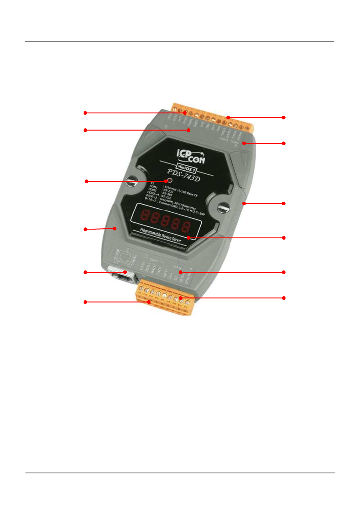
PDS-700/PPDS-700-MTCP Front View
Removable Terminal
DI/DO Channels
Wiring
LED Indicator
Robust
insulated and
fire retardant case
RJ-45 Jack for
10/100M Ethernet
and PoE (IEEE
Block for easy wiring
Serial Ports
DIN-Rail
for easy mounting
7-Segment LED
Wiring information
802.3af, Class 1)
COM1: RS-232
PDS Series User Manual ( V1.4, Oct. 2009) ----- 21
Page 22
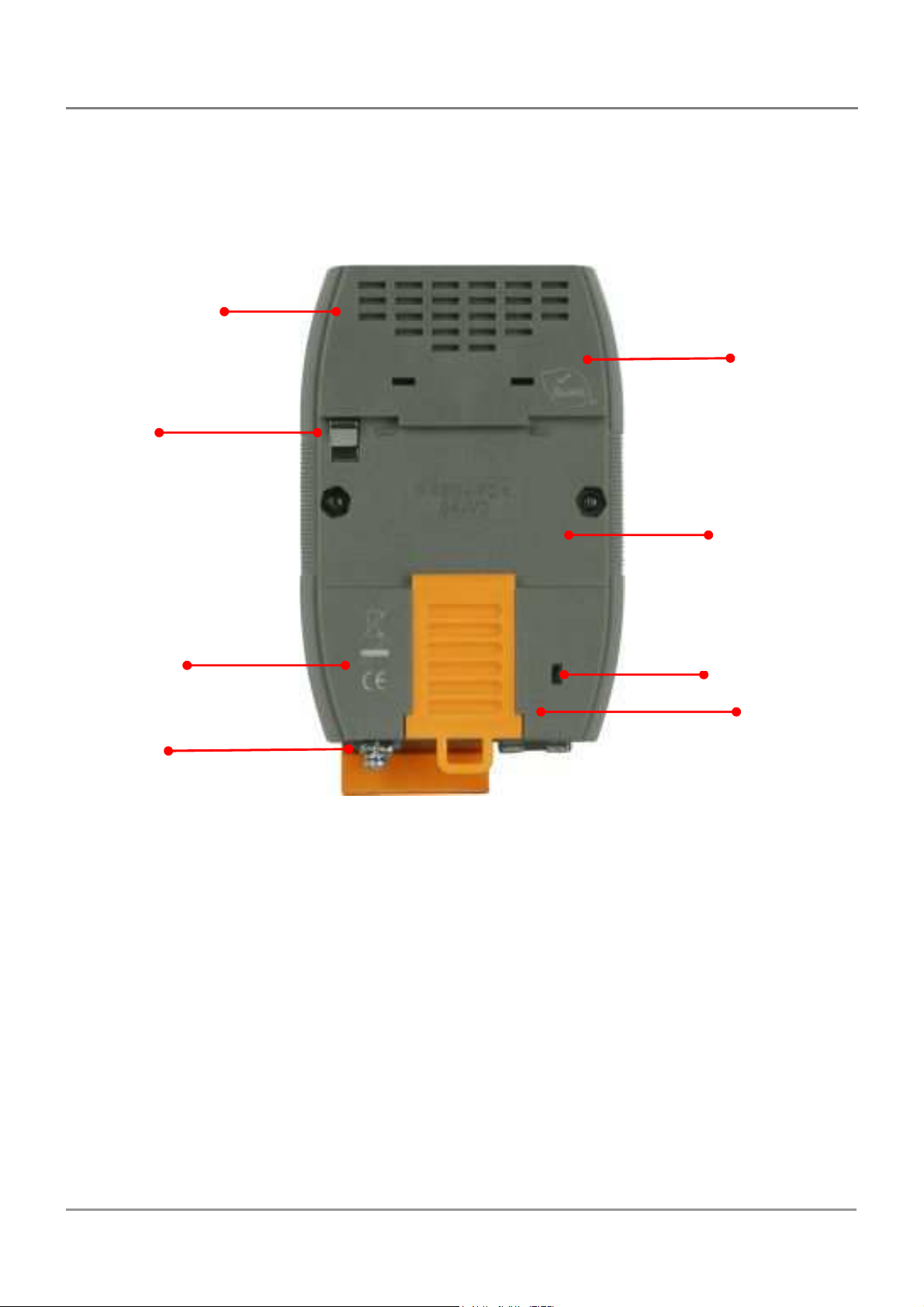
Frame Ground
(for PCB/device)
Frame Ground
DIN
-
Rail Mounting
PDS-700/PPDS-700-MTCP Rear ViewP
Robust, insulated and
fire retardant case
RoHS Compliance
CE Certification
(for PCB/device)
Initial Mode Switch
DIN-Rail Lock
PDS Series User Manual ( V1.4, Oct. 2009) ----- 22
Page 23
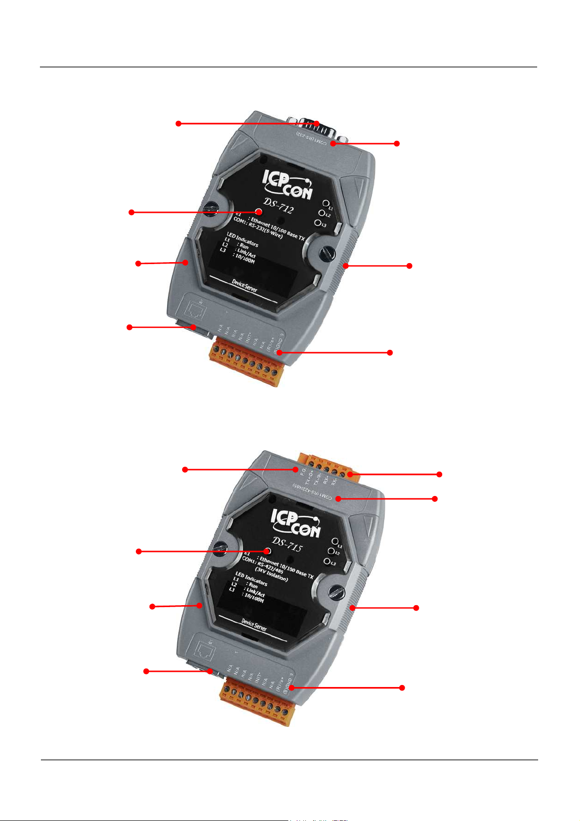
Wiring
i
nformation
LED Indicator
i
nformation
COM1: RS
-
422/485
LED Indicator
Wiring
i
nformation
DS-700 Front View
COM1: RS-232
Serial Ports
Robust
insulated and
fire retardant case
RJ-45 Jack for
10/100M Ethernet
Wiring
DIN-Rail
for easy mounting
Serial Ports
Robust
insulated and
DIN-Rail
for easy mounting
fire retardant case
RJ-45 Jack for
10/100M Ethernet
PDS Series User Manual ( V1.4, Oct. 2009) ----- 23
Page 24
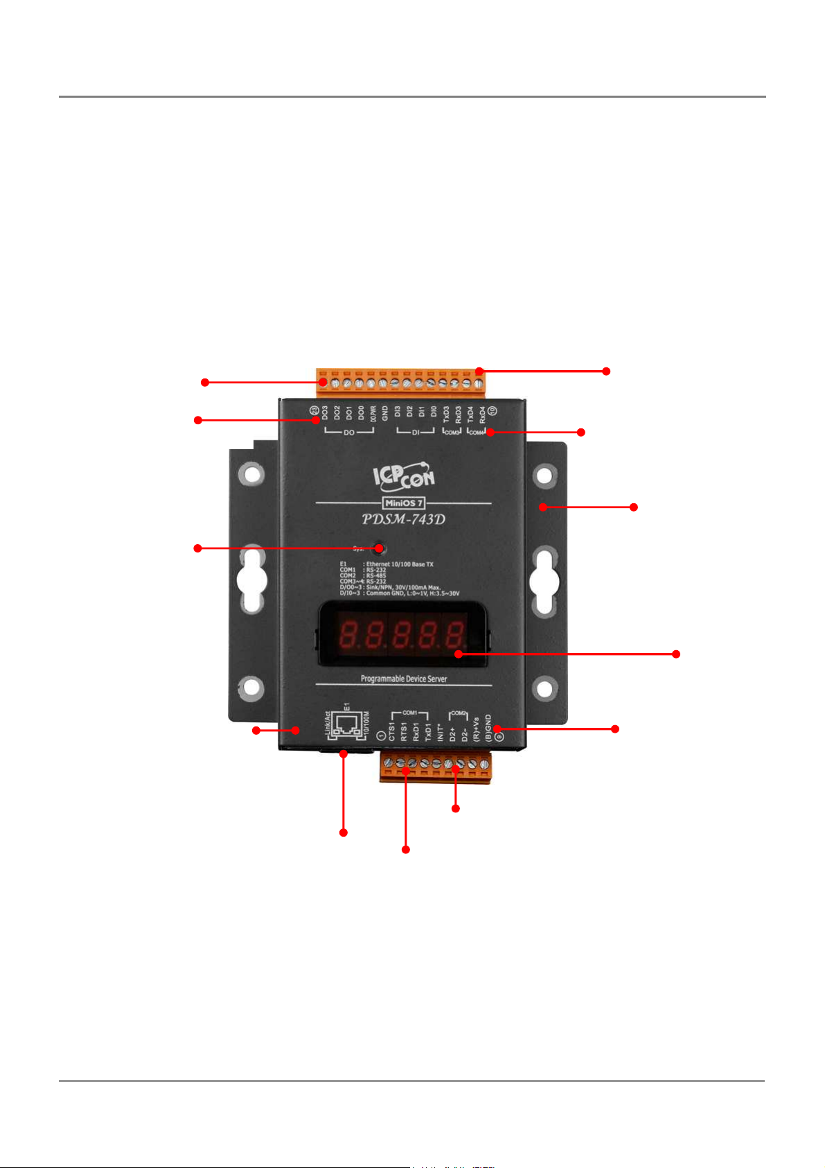
Wiring
i
nformation
COM2: RS
-
485
Metal c
ase
i
nformation
PDSM-700/PPDSM-700-MTCP Front View
DI/DO Channels
Wiring
LED Indicator
Removable Terminal
Block for easy wiring
Serial Ports
Frame Ground
7-Segment LED
Robust insulated
and fire retardant
RJ-45 Jack for 10/100M
Ethernet and PoE (IEEE
802.3af, Class 1)
COM1: RS-232
PDS Series User Manual ( V1.4, Oct. 2009) ----- 24
Page 25

3.3. PDS Comparison Table
PDS(M)-700(D) Series Programmable Device Servers
Model DI/DO COM1 COM2 COM3 COM4 COM5 COM6 COM7 COM8 Metal
PDS-720(D) -
PDS-721(D) -
PDSM-721(D)
PDS-732(D) -
PDSM-732(D)
PDS-734(D) -
PDSM-734(D)
PDS-742(D) -
PDSM-742(D)
5-wire
RS-232
5-wire
6/7
RS-232
5-wire
4/4
RS-232
5-wire
4/4
RS-232
5-wire
RS-232
2-wire
RS-485
2-wire
RS-485
2-wire
RS-485
2-wire
RS-485
2-wire
RS-485
- - - - - -
- - - - - -
5-wire
RS-232
4-wire
RS-422
5-wire
RS-232
- - - - -
- - - - -
9-wire
- - - -
RS-232
Yes
Yes
Yes
Yes
PDS-743(D) -
PDSM-743(D)
PDS-752(D) -
PDSM-752(D)
PDS-755(D) -
PDSM-755(D)
PDS-762(D) -
PDSM-762(D)
PDS-782(D) -
PDSM-782(D)
PDS-782(D)-
25
4/4
-
-
1/2
-
-
5-wire
RS-232
5-wire
RS-232
5-wire
RS-232
5-wire
RS-232
5-wire
RS-232
5-wire
RS-232
2-wire
RS-485
2-wire
RS-485
2-wire
RS-485
2-wire
RS-485
2-wire
RS-485
2-wire
RS-485
3-wire
RS-232
5-wire
RS-232
2-wire
RS-485
3-wire
RS-232
3-wire
RS-232
3-wire
RS-232
3-wire
RS-232
5-wire
RS-232
2-wire
RS-485
3-wire
RS-232
3-wire
RS-232
3-wire
RS-232
- - - -
5-wire
RS-232
2-wire
RS-485
3-wire
RS-232
3-wire
RS-232
3-wire
RS-232
- - -
- - -
3-wire
RS-232
3-wire
RS-232
3-wire
RS-232
- -
3-wire
RS-232
3-wire
RS-232
3-wire
RS-232
3-wire
RS-232
Yes
Yes
Yes
Yes
Yes
PDSM-700(D) = PDS-700(D) + Metal Casing
I-7188EN is the similar product with PDS-700(D)
PDS Series User Manual ( V1.4, Oct. 2009) ----- 25
Page 26
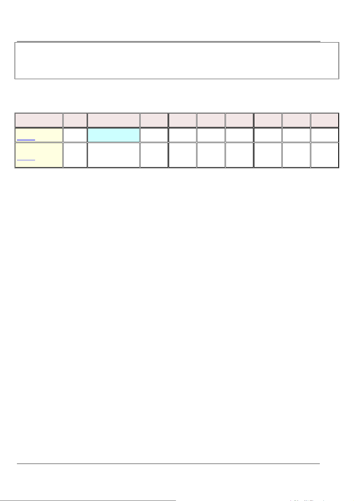
PDS-700D = PDS-700 + 7-Seg. LED Display
In the DI/DO column is the number of channels for each device.
Some PDS-700 doesn’t have DIO function.
DS-700 Series Non-Programmable Device Servers
Model DI/DO
DS-712 - 5-wire RS-232 - - - - - - -
DS-715 -
COM1 COM2 COM3 COM4 COM5 COM6 COM7 COM8
2-wire RS-485
- - - - - - -
4-wire RS-422
2-wire RS-485: Data+, Data- with Self-Tuner inside
4-wire RS-422: TxD+, TxD-, RxD+, RxD3-wire RS-232: RxD, TxD, GND
5-wire RS-232: RxD, TxD, CTS, RTS, GND
8-wire RS-232: RxD, TxD, CTS, RTS, DSR, DTR, DCD, GND
9-wire RS-232: RxD, TxD, CTS, RTS, DSR, DTR, DCD, RI, GND
PDS Series User Manual ( V1.4, Oct. 2009) ----- 26
Page 27
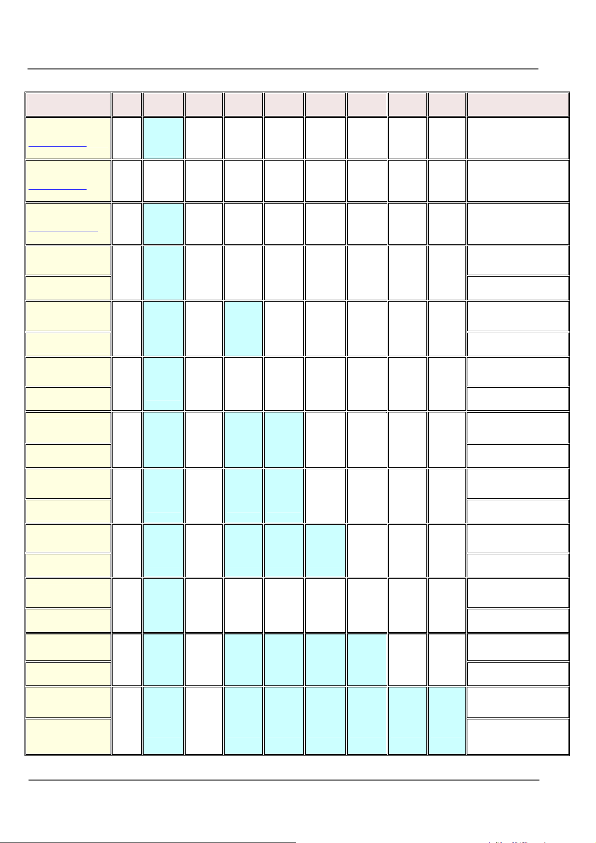
PPDS(M)-700(D)-MTCP Series Programmable Device Servers
Model DI/DO COM1 COM2 COM3 COM4 COM5 COM6 COM7 COM8
PPDS-712-MTCP -
PPDS-715-MTCP -
PPDS-720(D)-MTCP -
PPDS-721(D)-MTCP
6/7
PPDSM-721(D)-MTCP
PPDS-732(D)-MTCP
4/4
PPDSM-732(D)-MTCP
PPDS-734(D)-MTCP
4/4
PPDSM-734(D)-MTCP
5-wire
RS-232
RS-422
RS-485
5-wire
RS-232
5-wire
RS-232
5-wire
RS-232
5-wire
RS-232
- - - - - - -
- - - - - - -
2-wire
RS-485
2-wire
RS-485
2-wire
RS-485
2-wire
RS-485
- - - - - -
- - - - - -
5-wire
- - - - -
RS-232
4-wire
- - - - -
RS-422
Metal
-
-
-
-
Yes
-
Yes
-
Yes
PPDS-742(D)-MTCP
PPDSM-742(D)-MTCP
PPDS-743(D)-MTCP
PPDSM-743(D)-MTCP
PPDS-752(D)-MTCP
PPDSM-752(D)-MTCP
PPDS-755(D)-MTCP
PPDSM-755(D)-MTCP
PPDS-762(D)-MTCP
PPDSM-762(D)-MTCP
PPDS-782(D)-MTCP
PPDSM-782(D)-MTCP
-
4/4
-
-
1/2
-
5-wire
RS-232
5-wire
RS-232
5-wire
RS-232
5-wire
RS-232
5-wire
RS-232
5-wire
RS-232
2-wire
RS-485
2-wire
RS-485
2-wire
RS-485
2-wire
RS-485
2-wire
RS-485
2-wire
RS-485
5-wire
RS-232
3-wire
RS-232
5-wire
RS-232
2-wire
RS-485
3-wire
RS-232
3-wire
RS-232
9-wire
RS-232
3-wire
RS-232
5-wire
RS-232
2-wire
RS-485
3-wire
RS-232
3-wire
RS-232
- - - -
- - - -
5-wire
RS-232
2-wire
RS-485
3-wire
RS-232
3-wire
RS-232
- - -
- - -
3-wire
RS-232
3-wire
RS-232
- -
3-wire
RS-232
3-wire
RS-232
-
Yes
Yes
Yes
Yes
Yes
Yes
PDS Series User Manual ( V1.4, Oct. 2009) ----- 27
Page 28
PPDS-700(D)-MTCP = PDS-700(D) + PoE + Modbus
PPDS-700D-MTCP = PPDS-700-MTCP + 7-Seg. LED Display
In the DI/DO column is the number of channels for each device.
Some PPDS-700-MTCP doesn’t have DIO function.
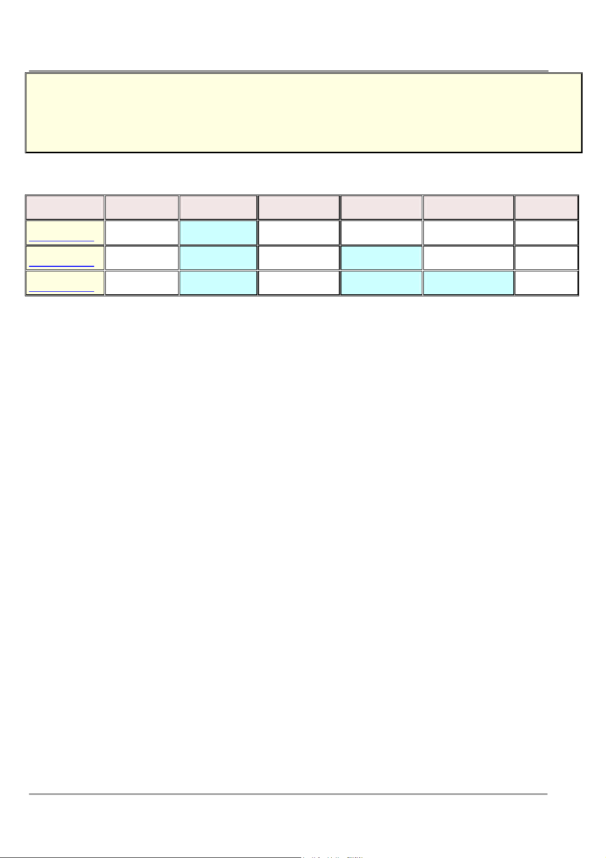
PPDS-700-IP67 Series Programmable Device Servers
Model Ethernet COM1 COM2 COM3 COM4 IP67
PPDS-741-IP67 10/100 M, PoE 5-wire RS-232 2-wire RS-485 2-wire RS-485 2-wire RS-485 Yes
PPDS-742-IP67 10/100 M, PoE 5-wire RS-232 2-wire RS-485 5-wire RS-232 2-wire RS-485 Yes
PPDS-743-IP67 10/100 M, PoE 5-wire RS-232 2-wire RS-485 -5-wire RS-232 5-wire RS-232 Yes
2-wire RS-485: Data+, Data- with Self-Tuner inside
4-wire RS-422: TxD+, TxD-, RxD+, RxD3-wire RS-232: RxD, TxD, GND
5-wire RS-232: RxD, TxD, CTS, RTS, GND
8-wire RS-232: RxD, TxD, CTS, RTS, DSR, DTR, DCD, GND
9-wire RS-232: RxD, TxD, CTS, RTS, DSR, DTR, DCD, RI, GND
PDS Series User Manual ( V1.4, Oct. 2009) ----- 28
Page 29
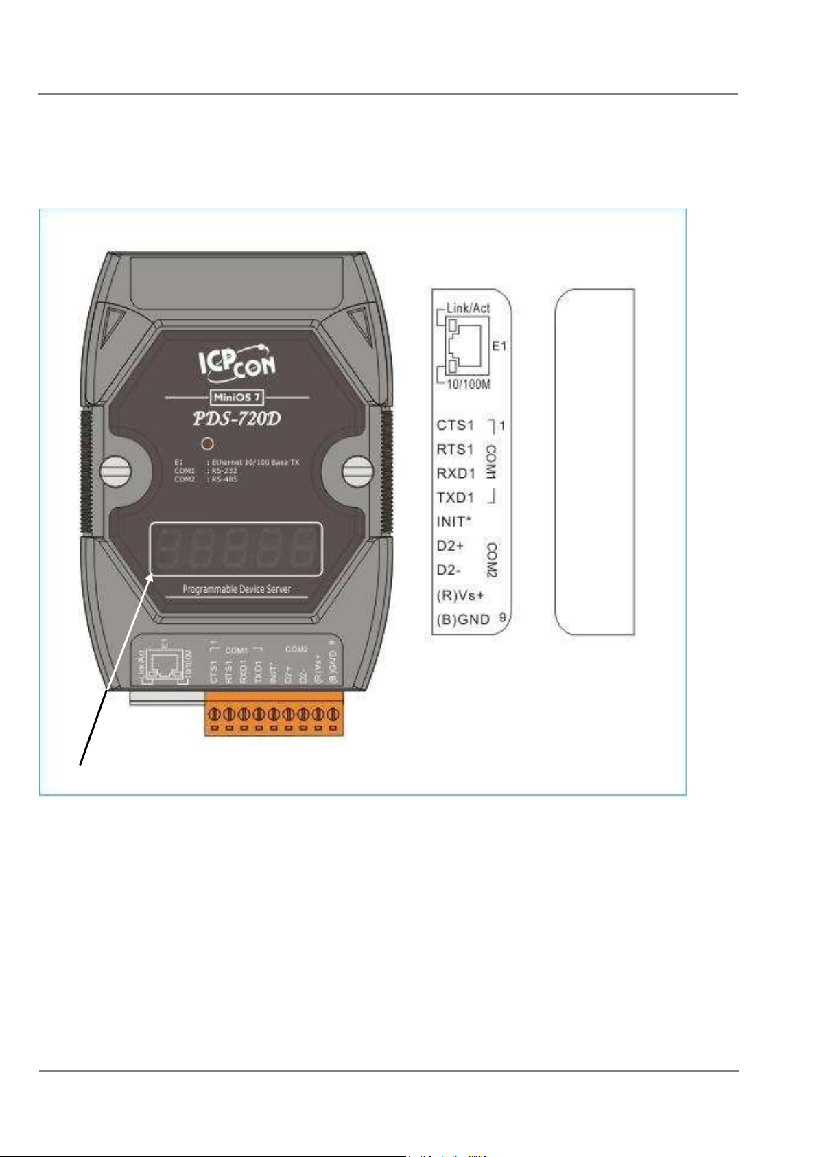
3.4. Pin Assignments
Pin Assignments for PDS-720(D)/PPDS-720(D)-MTCP models
Only D-version modules have a 5-digit 7-SEG LED.
PDS Series User Manual ( V1.4, Oct. 2009) ----- 29
Page 30

Pin Name Description
1 CTS1 CTS pin
2 RTS1 RTS pin
3 RXD1 RXD pin
4 TXD1
COM1
(RS-232)
TXD pin
5 INIT* Initialization pin (for enabling/disabling AUTOEXEC.BAT)
6 D2+ Data+ pin
7 D2-
COM2
(RS-485)
Data- pin
8 VS+ V+ Pin for the power supply (+10 ~ +30 VDC unregulated)
9 GND GND Pin for the power supply (COM1 GND)
- E1
10/100 Base-TX and PoE (IEEE 802.3af, Class 1)
PDS Series User Manual ( V1.4, Oct. 2009) ----- 30
Page 31
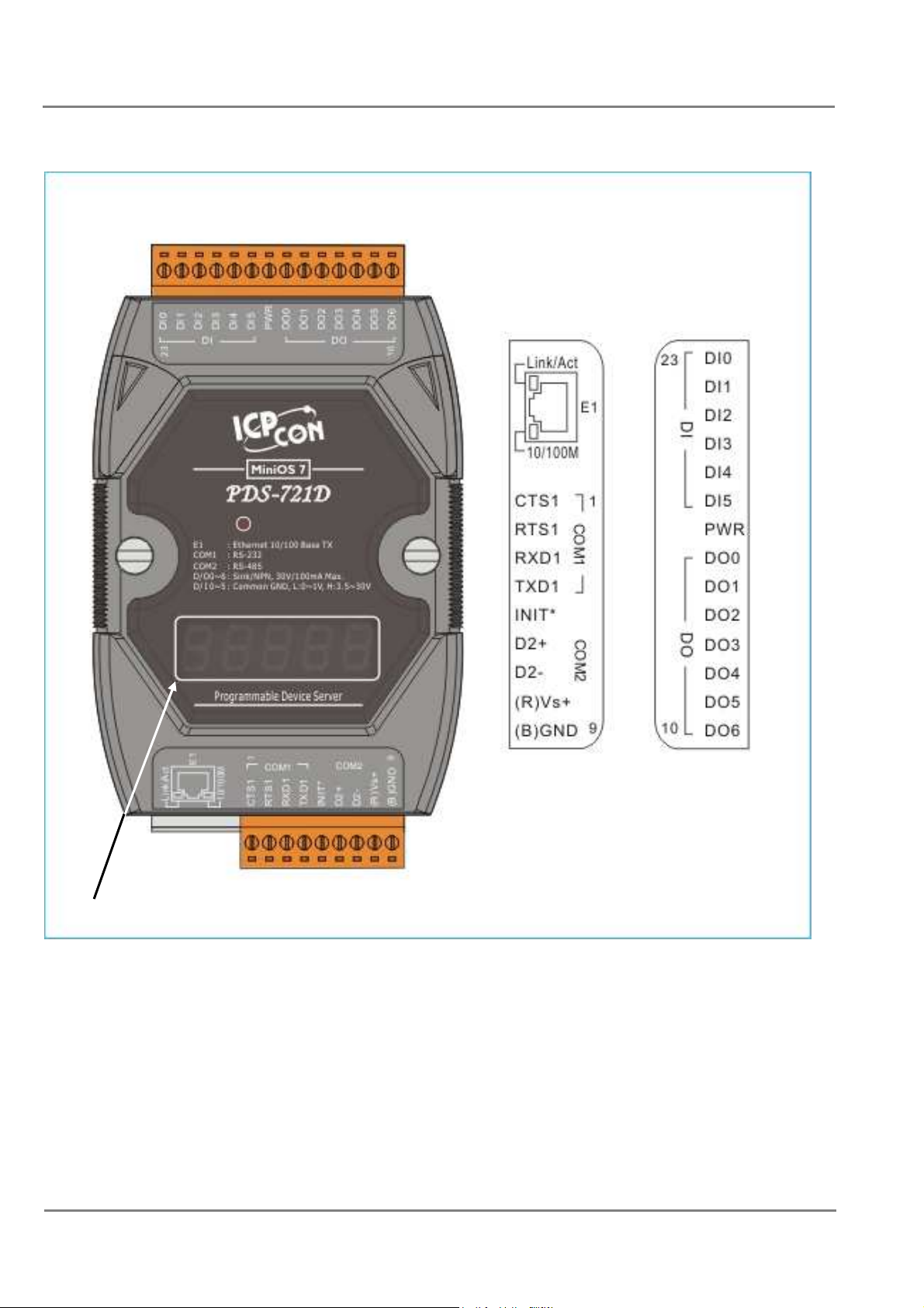
PDS-721(D)/PPDS-721(D)-MTCP Pin Assignments
Only D-version modules have a 5-digit 7-SEG LED.
PDS Series User Manual ( V1.4, Oct. 2009) ----- 31
Page 32
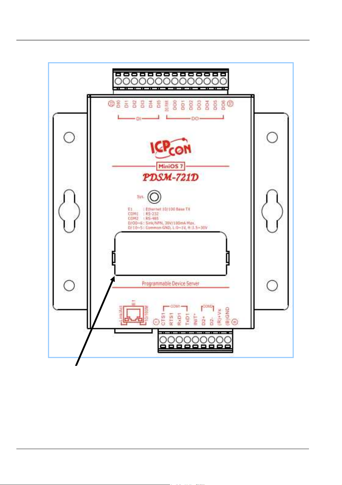
PDSM-721(D)/PPDSM-721(D)-MTCP Pin Assignments
Only D-version modules have a 5-digit 7-SEG LED
PDS Series User Manual ( V1.4, Oct. 2009) ----- 32
Page 33
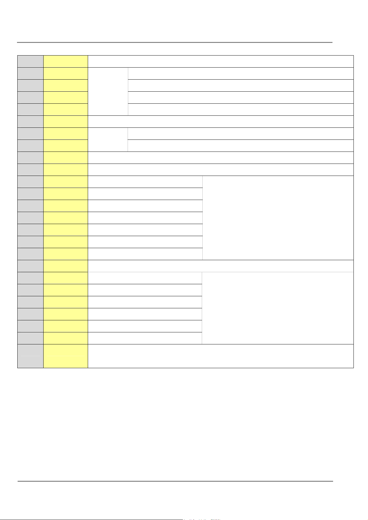
Pin Name Description
1 CTS1 CTS pin
2 RTS1 RTS pin
3 RXD1 RXD pin
4 TXD1
COM1
(RS-232)
TXD pin
5 INIT* Initialization pin (for enabling/disabling AUTOEXEC.BAT)
6 D2+ Data+ pin
7 D2-
COM2
(RS-485)
Data- pin
8 VS+ V+ Pin for the power supply (+10 ~ +30 VDC unregulated)
9 GND GND Pin for the power supply (COM1 GND)
10 DO6 Digital Output channel 6
11 DO5 Digital Output channel 5
12 DO4 Digital Output channel 4
13 DO3 Digital Output channel 3
100 mA, 30 V max.
14 DO2 Digital Output channel 2
15 DO1 Digital Output channel 1
16 DO0 Digital Output channel 0
17 DO.PWR Power Input for Digital Output
18 DI5 Digital Input channel 5
19 DI4 Digital Input channel 4
20 DI3 Digital Input channel 3
21 DI2 Digital Input channel 2
22 DI1 Digital Input channel 1
23 DI0 Digital Input channel 0
- E1 1. 10/100 Base-TX
2. PoE (IEEE 802.3af, Class 1)_Only for PoE version
3.5 V ~ 30 V
PDS Series User Manual ( V1.4, Oct. 2009) ----- 33
Page 34
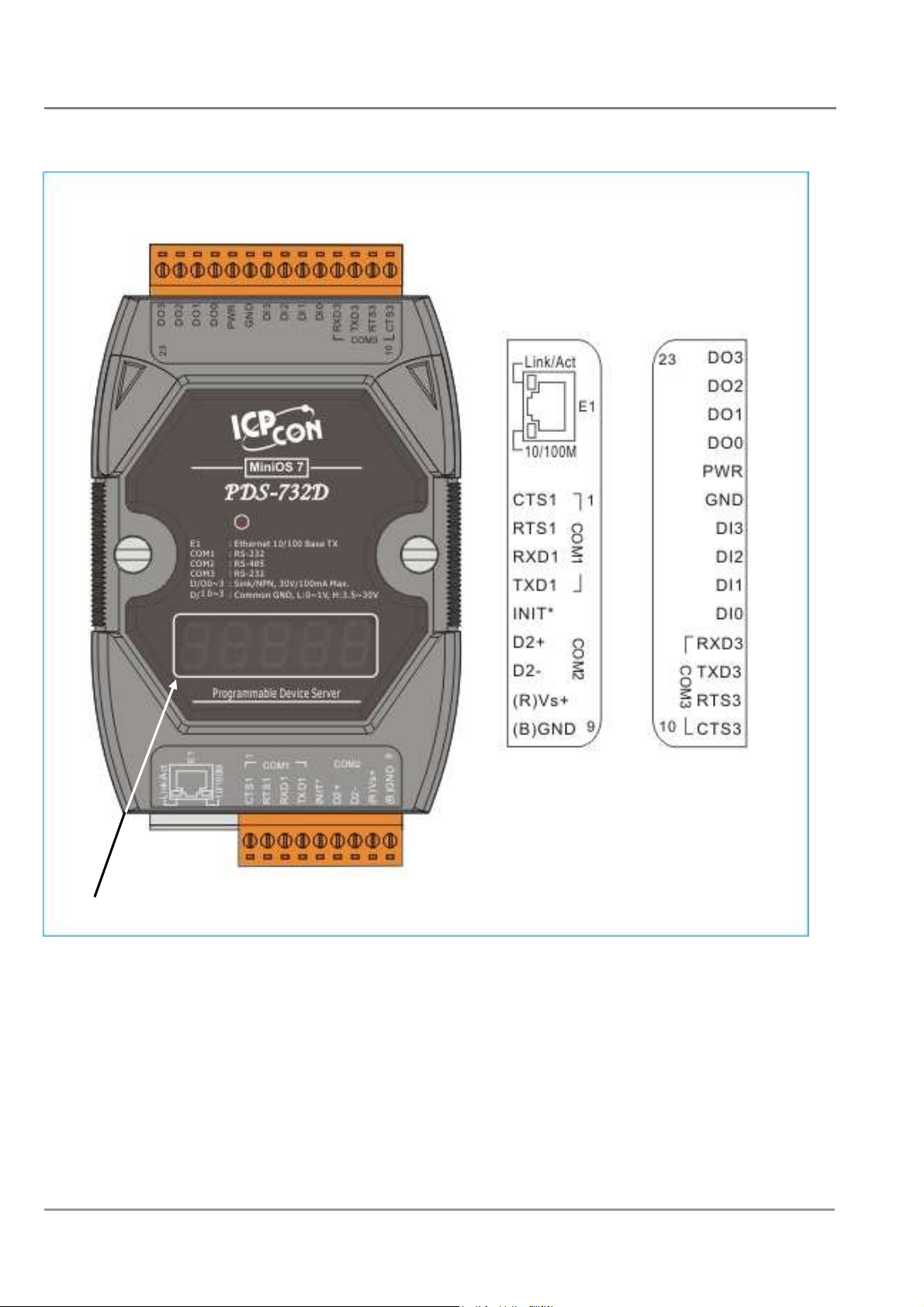
PDS-732(D)/PPDS-732(D)-MTCP Pin Assignments
Only D-version modules have a 5-digit 7-SEG LED.
PDS Series User Manual ( V1.4, Oct. 2009) ----- 34
Page 35
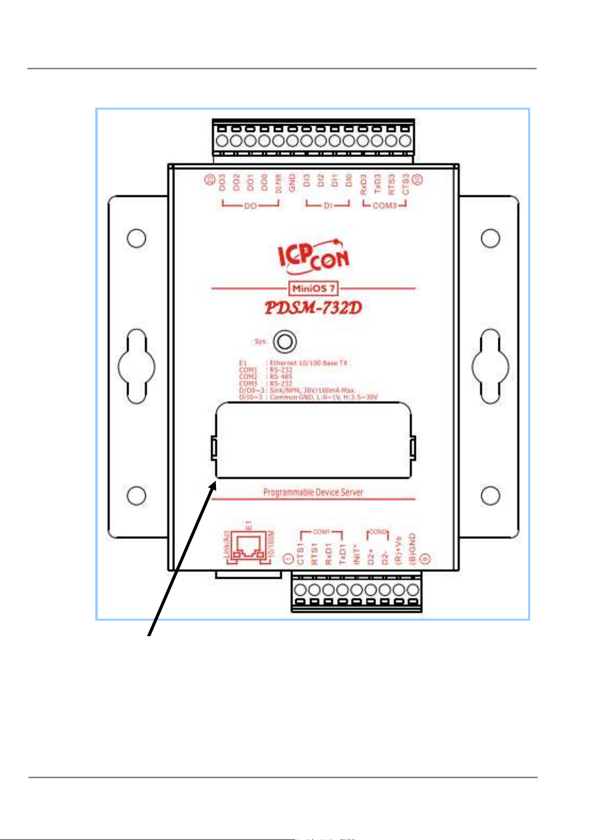
PDSM-732(D)/PPDSM-732(D)-MTCP Pin Assignment
Only D-version modules have a 5-digit 7-SEG LED
PDS Series User Manual ( V1.4, Oct. 2009) ----- 35
Page 36
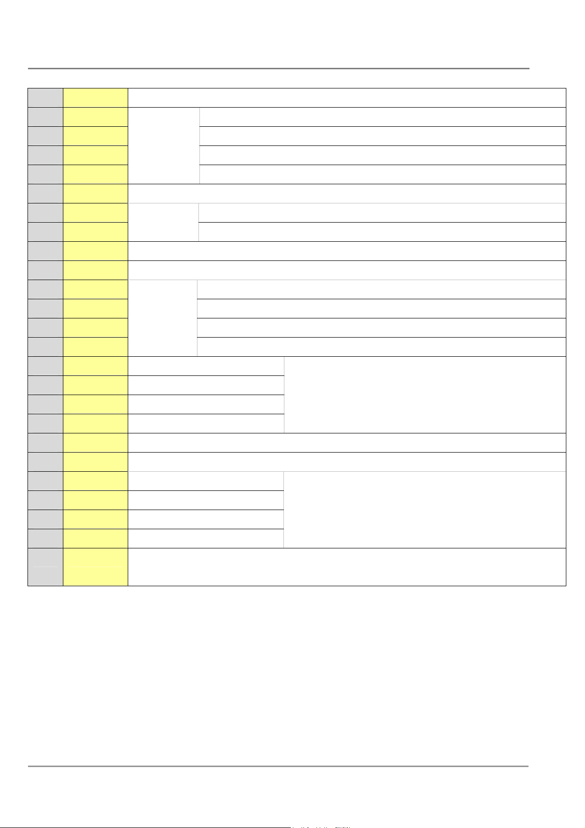
Pin Name Description
1 CTS1 CTS pin
2 RTS1 RTS pin
3 RXD1 RXD pin
4 TXD1
COM1
(RS-232)
TXD pin
5 INIT* Initialization pin (for enabling/disabling AUTOEXEC.BAT)
6 D2+ Data+ pin
7 D2-
COM2
(RS-485)
Data- pin
8 VS+ V+ pin for the power supply (+10 ~ +30 VDC unregulated)
9 GND GND pin for the power supply (COM1 GND)
10 CTS3 CTS pin
11 RTS3 RTS pin
12 TXD3 TXD pin
13 RXD3
COM3
(RS-232)
RXD pin
14 DI0 Digital Input channel 0
15 DI1 Digital Input channel 1
3.5 V ~ 30 V
16 DI2 Digital Input channel 2
17 DI3 Digital Input channel 3
18 DO.GND GND pin for the Digital Output (COM3 GND)
19 PWR Power Input for Digital Output
20 DO0 Digital Output channel 0
21 DO1 Digital Output channel 1
100 mA, 30 V max.
22 DO2 Digital Output channel 2
23 DO3 Digital Output channel 3
- E1 1. 10/100 Base-TX
2. PoE (IEEE 802.3af, Class 1)_Only for PoE version
PDS Series User Manual ( V1.4, Oct. 2009) ----- 36
Page 37
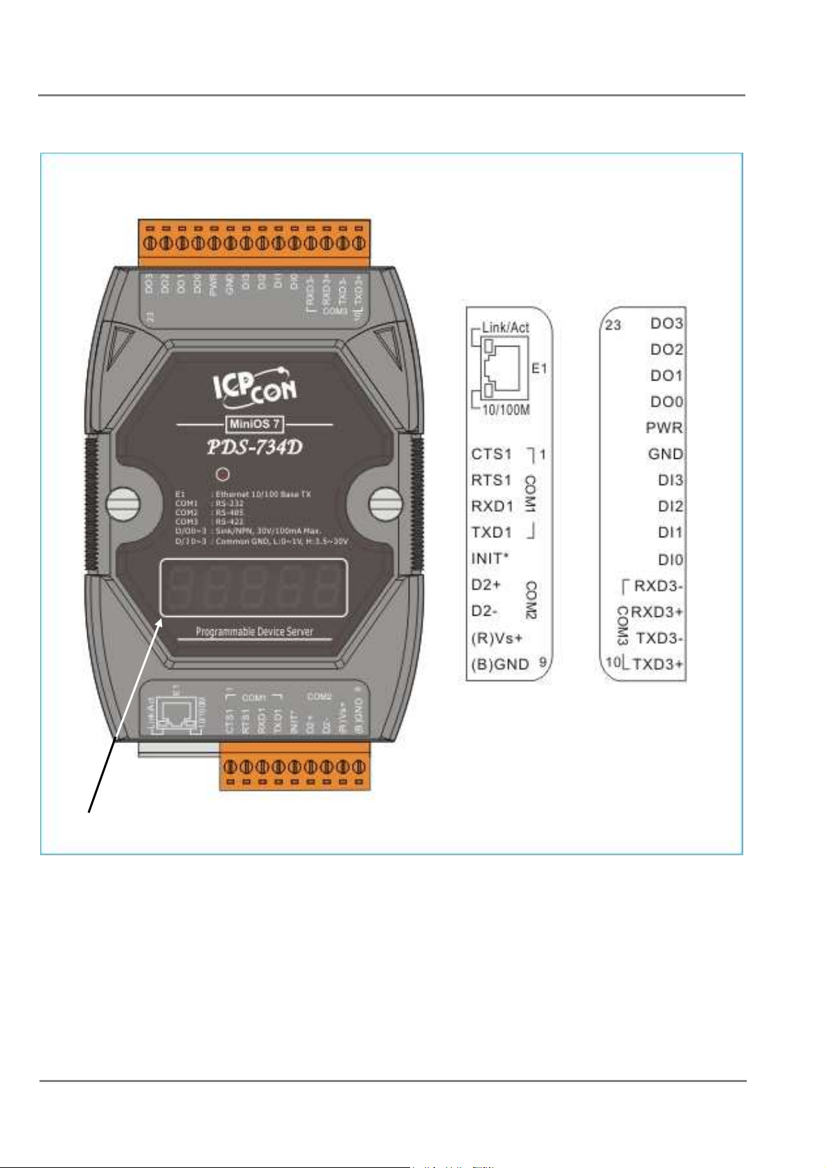
PDS-734(D)/PPDS-734(D)-MTCP Pin Assignments
Only D-version modules have a 5-digit 7-SEG LED.
PDS Series User Manual ( V1.4, Oct. 2009) ----- 37
Page 38
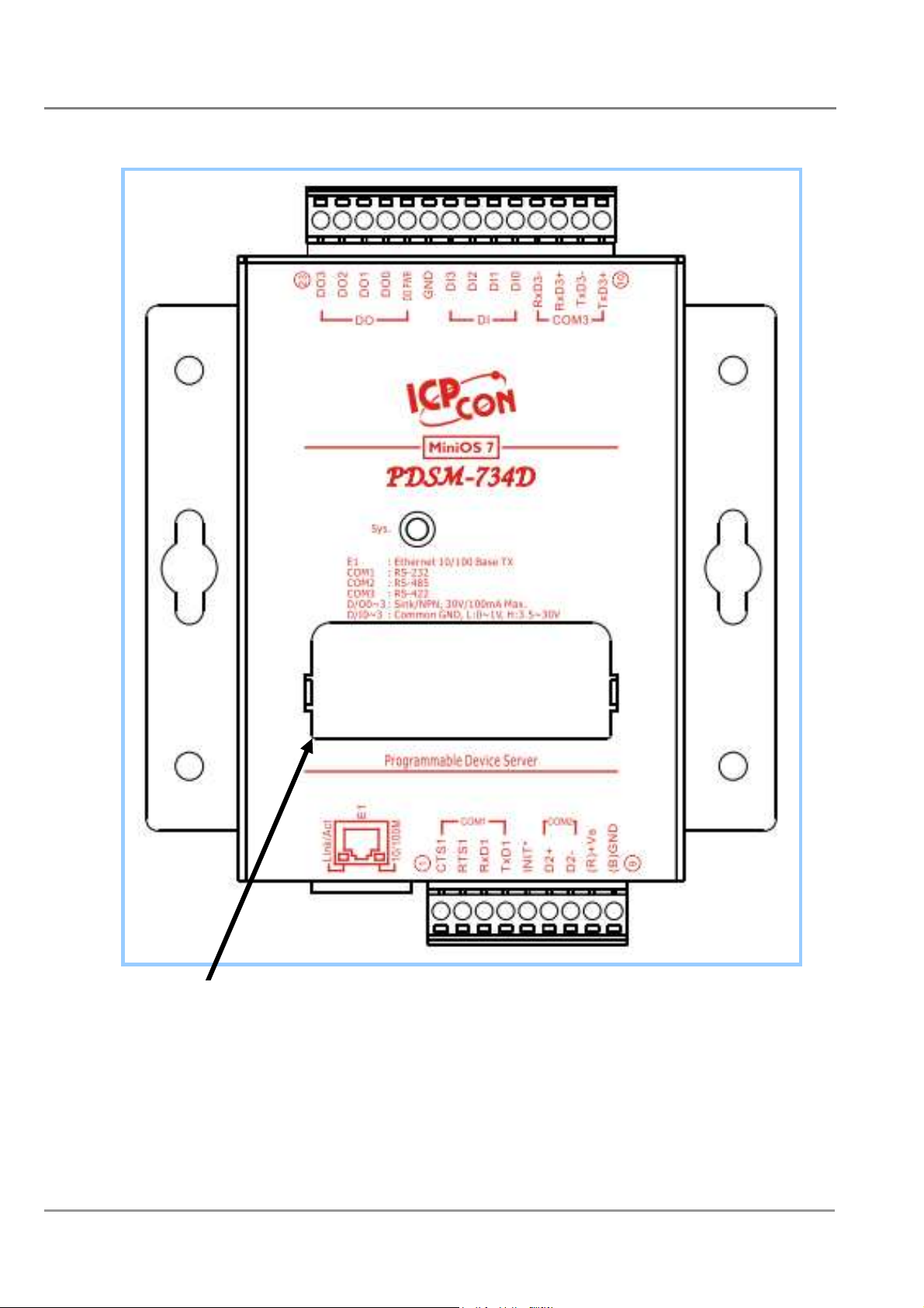
PDSM-734(D)/PPDSM-734(D)-MTCP Pin Assignments
Only D-version modules have a 5-digit 7-SEG LED
PDS Series User Manual ( V1.4, Oct. 2009) ----- 38
Page 39

Pin
Name Description
1 CTS1 CTS pin
2 RTS1 RTS pin
3 RXD1 RXD pin
4 TXD1
COM1
(RS-232)
TXD pin
5 INIT* Initialization pin (for enabling/disabling AUTOEXEC.BAT)
6 D2+ Data+ pin
7 D2-
COM2
(RS-485)
Data- pin
8 VS+ V+ pin for the power supply (+10 ~ +30 VDC unregulated)
9 GND GND pin for the power supply (COM1 GND)
COM3
10 TXD3+
TXD+ pin
(RS-422/RS-485)
COM3
11 TXD3-
TXD- pin
(RS-422/RS-485)
COM3
12 RXD3+
RXD+ pin
(RS-422)
13 RXD3-
RXD- pin
(RS-422)
14 DI0 Digital Input channel 0
15 DI1 Digital Input channel 1
16 DI2 Digital Input channel 2
17 DI3 Digital Input channel 3
18 GND GND pin for the Digital Output
19 PWR Power Input for Digital Output
20 DO0 Digital Output channel 0
21 DO1 Digital Output channel 1
22 DO2 Digital Output channel 2
23 DO3 Digital Output channel 3
1. 10/100 Base-TX
- E1
2. PoE (IEEE 802.3af, Class 1)_Only for PoE version
COM3
3.5 V ~ 30 V
100 mA, 30 V max.
PDS Series User Manual ( V1.4, Oct. 2009) ----- 39
Page 40
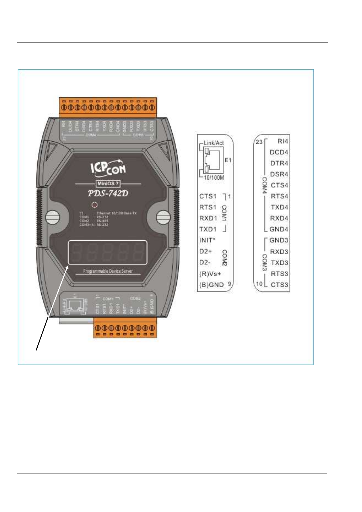
PDS-742(D)/PPDS-742(D)-MTCP Pin Assignments
Only D-version modules have a 5-digit 7-SEG LED.
PDS Series User Manual ( V1.4, Oct. 2009) ----- 40
Page 41
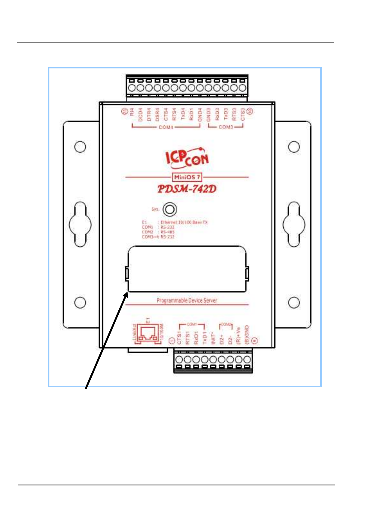
PDSM-742(D)/PPDSM-742(D)-MTCP Pin Assignments
Only D-version modules have a 5-digit 7-SEG LED
PDS Series User Manual ( V1.4, Oct. 2009) ----- 41
Page 42

Pin
Name Description
1 CTS1 CTS pin
2 RTS1 RTS pin
3 RXD1 RXD pin
4 TXD1
COM1
(RS-232)
TXD pin
Initialization pin (for enabling/disabling
5 INIT*
AUTOEXEC.BAT)
6 D2+ Data+ pin
7 D2-
COM2
(RS-485)
Data- pin
V+ pin for the power supply (+10 ~ +30 VDC
8 VS+
unregulated)
9 GND GND pin for the power supply (COM1 GND)
10 CTS3 CTS pin
11 RTS3 RTS pin
COM3
12 TXD3 TXD pin
(RS-232)
13 RXD3 RXD pin
14 GND3
GND pin
15 GND4 GND pin
16 RXD4 RXD pin
17 TXD4 TXD pin
18 RTS4 RTS pin
COM4
19 CTS4 CTS pin
(RS-232)
20 DSR4 DSR pin
21 DTR4 DTR pin
22 DCD4 DCD pin
23 RI4
RI pin
1. 10/100 Base-TX
- E1
2. PoE (IEEE 802.3af, Class 1)_Only for PoE version
PDS Series User Manual ( V1.4, Oct. 2009) ----- 42
Page 43
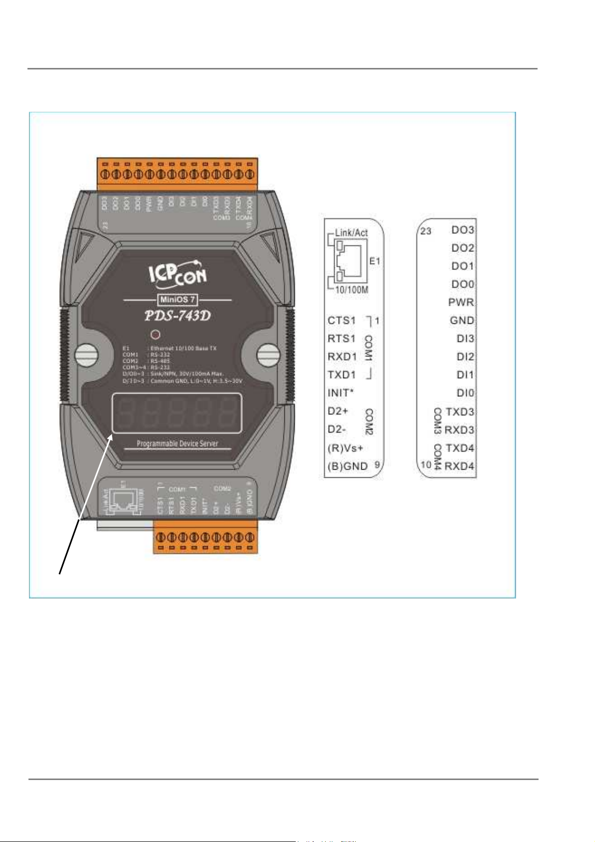
PDS-743(D)/PPDS-743(D)-MTCP Pin Assignments
Only D-version modules have a 5-digit 7-SEG LED.
PDS Series User Manual ( V1.4, Oct. 2009) ----- 43
Page 44
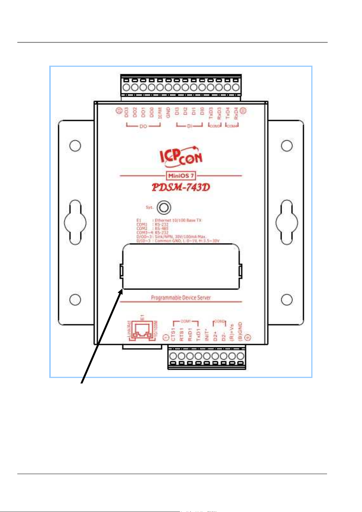
PDSM-743(D)/PPDSM-743(D)-MTCP Pin Assignments
Only D-version modules have a 5-digit 7-SEG LED
PDS Series User Manual ( V1.4, Oct. 2009) ----- 44
Page 45
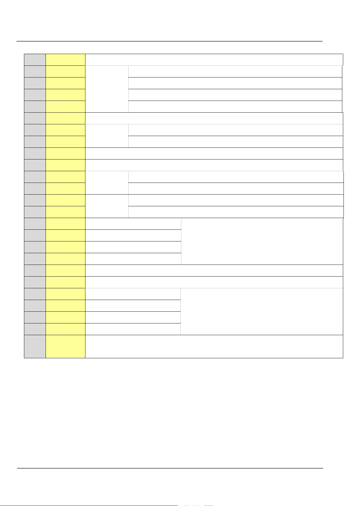
Pin
Name Description
1 CTS1 CTS pin
2 RTS1 RTS pin
3 RXD1 RXD pin
4 TXD1
COM1
(RS-232)
TXD pin
5 INIT* Initialization pin (for enabling/disabling AUTOEXEC.BAT)
6 D2+ Data+ pin
7 D2-
COM2
(RS-485)
Data- pin
8 VS+ V+ pin for the power supply (+10 ~ +30 VDC unregulated)
9 GND GND pin for the power supply (COM1 GND)
10 RXD4 RXD pin
11 TXD4
12 RXD3 RXD pin
13 TXD3
COM4
(RS-232)
COM3
(RS-232)
TXD pin
TXD pin
14 DI0 Digital Input channel 0
15 DI1 Digital Input channel 1
3.5 V ~ 30 V
16 DI2 Digital Input channel 2
17 DI3 Digital Input channel 3
18 GND GND pin for the Digital Output (COM3/COM4 GND)
19 DO.PWR Power Input for Digital Output
20 DO0 Digital Output channel 0
21 DO1 Digital Output channel 1
100 mA, 30 V max.
22 DO2 Digital Output channel 2
23 DO3 Digital Output channel 3
1. 10/100 Base-TX
- E1
2. PoE (IEEE 802.3af, Class 1)_Only for PoE version
PDS Series User Manual ( V1.4, Oct. 2009) ----- 45
Page 46
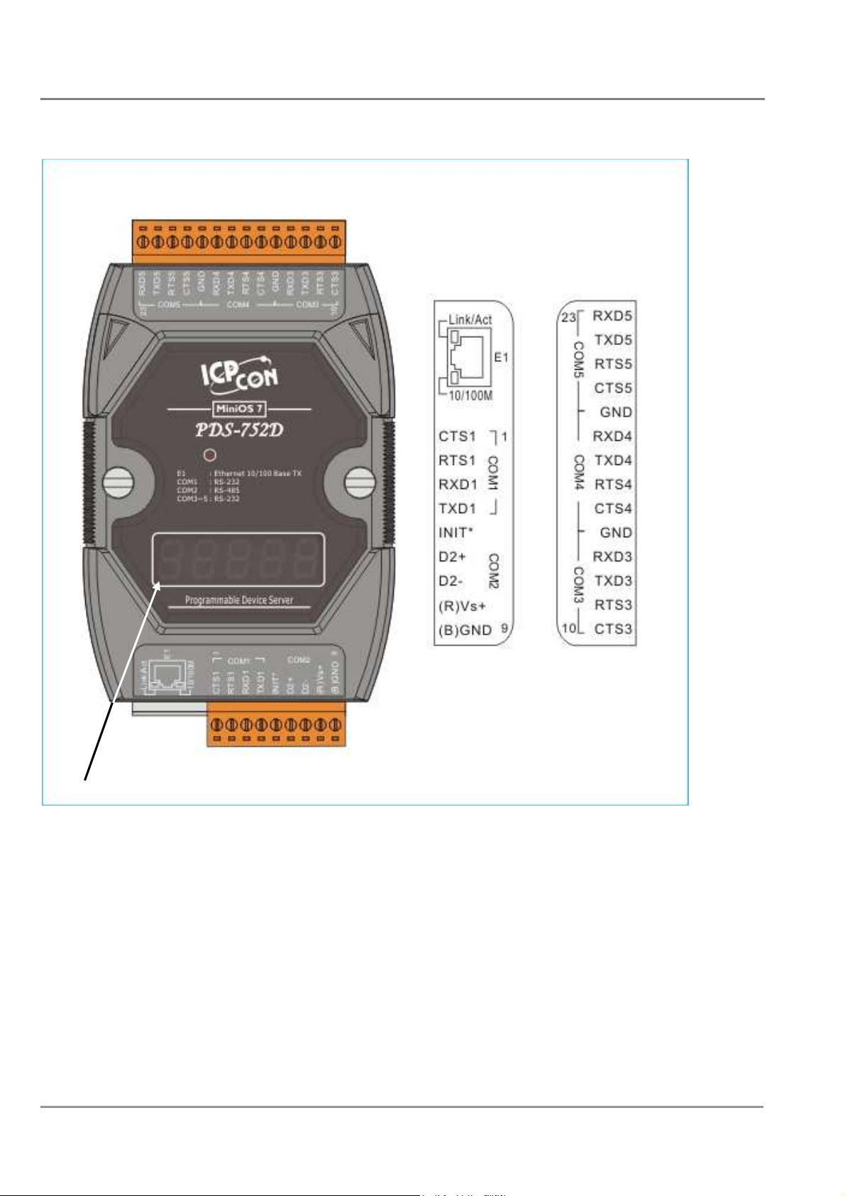
PDS-752(D)/PPDS-752(D)-MTCP Pin Assignments
Only D-version modules have a 5-digit 7-SEG LED.
PDS Series User Manual ( V1.4, Oct. 2009) ----- 46
Page 47
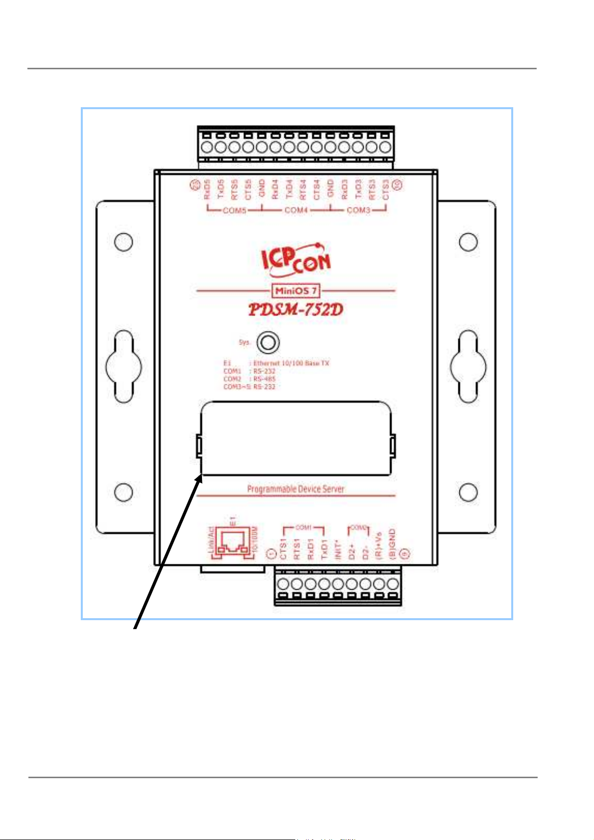
PDSM-752(D)/PPDSM-752(D)-MTCP Pin Assignment
Only D-version modules have a 5-digit 7-SEG LED
PDS Series User Manual ( V1.4, Oct. 2009) ----- 47
Page 48

Pin Name Description
1 CTS1 CTS pin
2 RTS1 RTS pin
3 RXD1 RXD pin
4 TXD1
COM1
(RS-232)
TXD pin
5 INIT* Initialization pin (for enabling/disabling AUTOEXEC.BAT)
6 D2+ Data+ pin
7 D2-
COM2
(RS-485) Data- pin
8 VS+ V+ pin for the power supply (+10 ~ +30 VDC unregulated)
9 GND GND pin for the power supply (COM1 GND)
10 CTS3 CTS pin
11 RTS3 RTS pin
12 TXD3 TXD pin
13 RXD3
COM3
(RS-232)
RXD pin
14 GND COM3/COM4 GND pin (RS-232)
15 CTS4 CTS pin
16 RTS4 RTS pin
COM4
17 TXD4 TXD pin
18 RXD4
(RS-232)
RXD pin
19 GND COM4/COM5 GND pin (RS-232)
20 CTS5 CTS pin
21 RTS5 RTS pin
22 TXD5 TXD pin
23 RXD5
COM5
(RS-232)
RXD pin
1. 10/100 Base-TX
- E1
2. PoE (IEEE 802.3af, Class 1)_Only for PoE version
PDS Series User Manual ( V1.4, Oct. 2009) ----- 48
Page 49
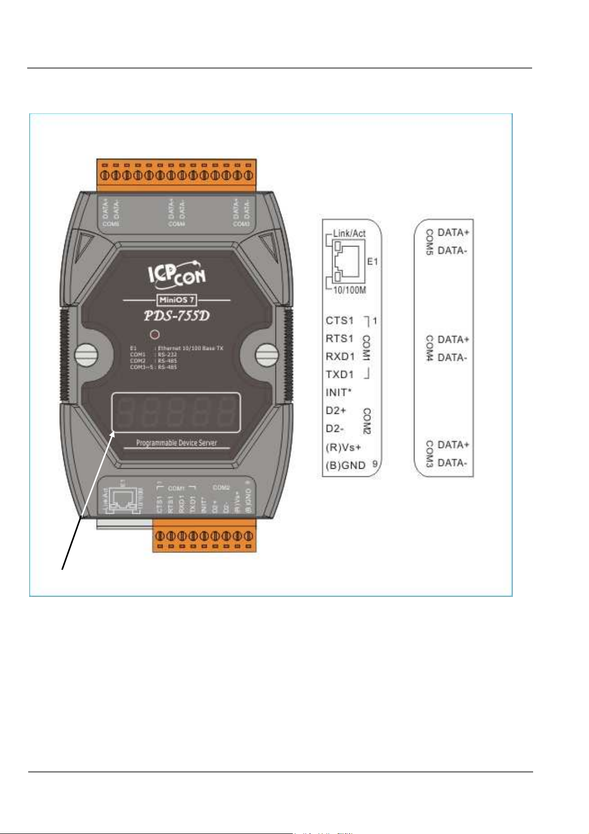
PDS-755(D)/PPDS-755(D)-MTCP Pin Assignments
Only D-version modules have a 5-digit 7-SEG LED.
PDS Series User Manual ( V1.4, Oct. 2009) ----- 49
Page 50
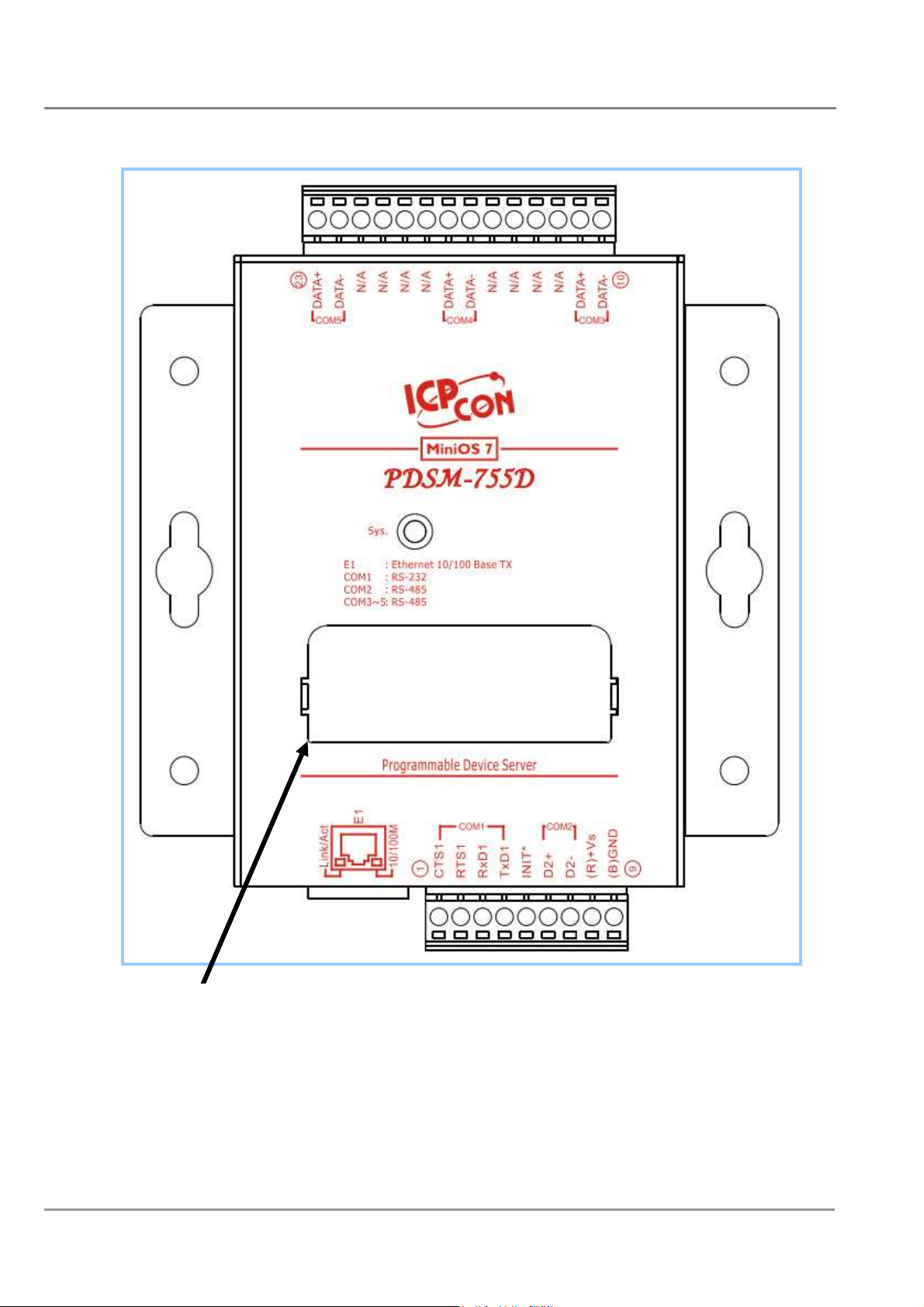
PDSM-755(D)/PPDSM-755(D)-MTCP Pin Assignments
Only D-version modules have a 5-digit 7-SEG LED
PDS Series User Manual ( V1.4, Oct. 2009) ----- 50
Page 51
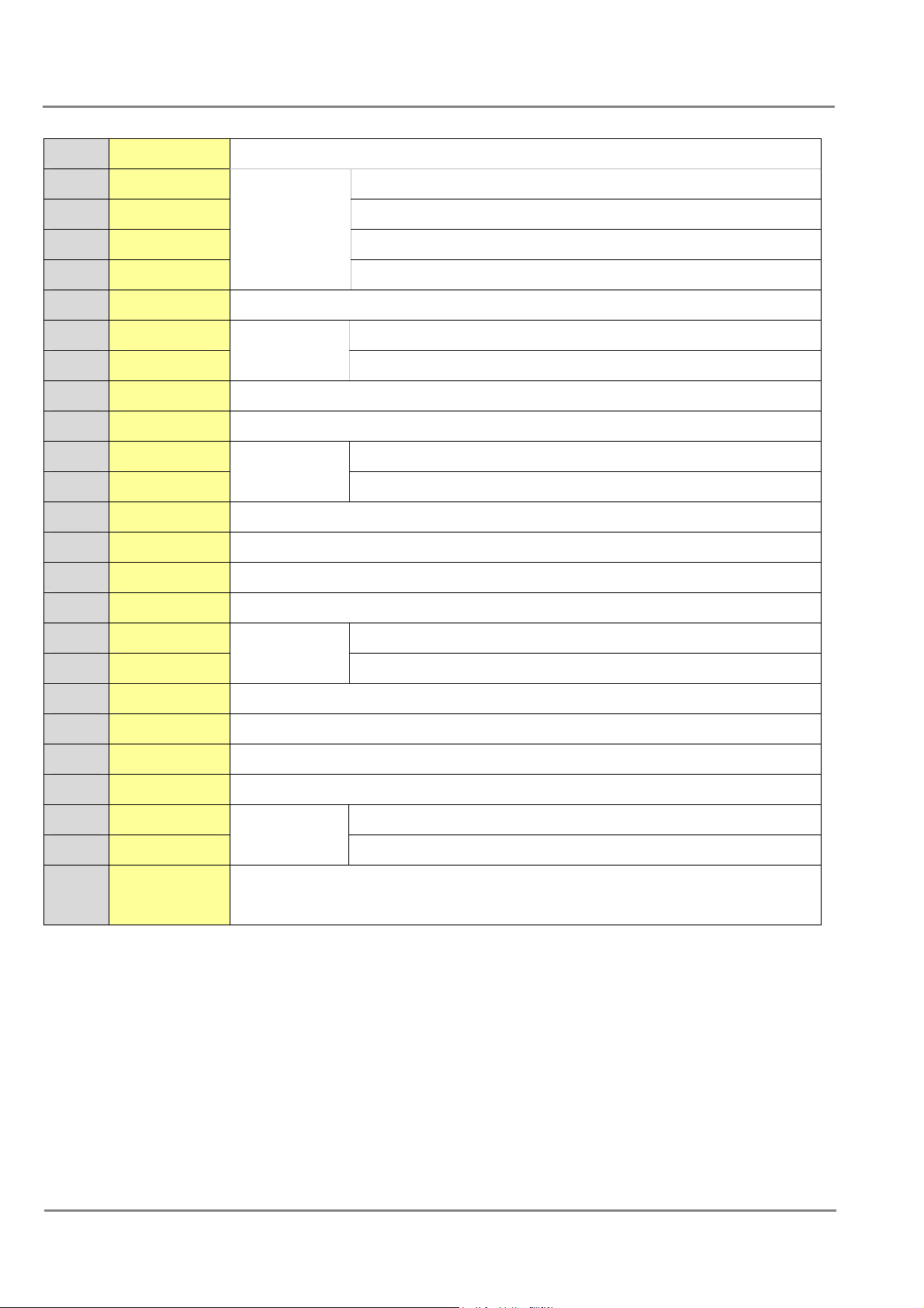
Pin Name Description
1 CTS1 CTS pin
2 RTS1 RTS pin
3 RXD1
4 TXD1
COM1
(RS-232)
RXD pin
TXD pin
5 INIT* Initialization pin (for enabling/disabling AUTOEXEC.BAT)
6 D2+ Data+ pin
7 D2-
COM2
(RS-485)
Data- pin
8 VS+ V+ pin for the power supply (+10 ~ +30 VDC unregulated)
9 GND GND pin for the power supply (COM1 GND)
10 D3- Data- pin
11 D3+
COM3
(RS-485)
Data+ pin
12 - N.C.
13 - N.C.
14 - N.C.
15 - N.C.
16 D4- Data- pin
COM4
17 D4+
(RS-485)
Data+ pin
18 - N.C.
19 - N.C.
20 - N.C.
21 - N.C.
22 D5- Data- pin
23 D5+
COM5
(RS-485)
Data+ pin
1. 10/100 Base-TX
- E1
2. PoE (IEEE 802.3af, Class 1)_Only for PoE version
PDS Series User Manual ( V1.4, Oct. 2009) ----- 51
Page 52
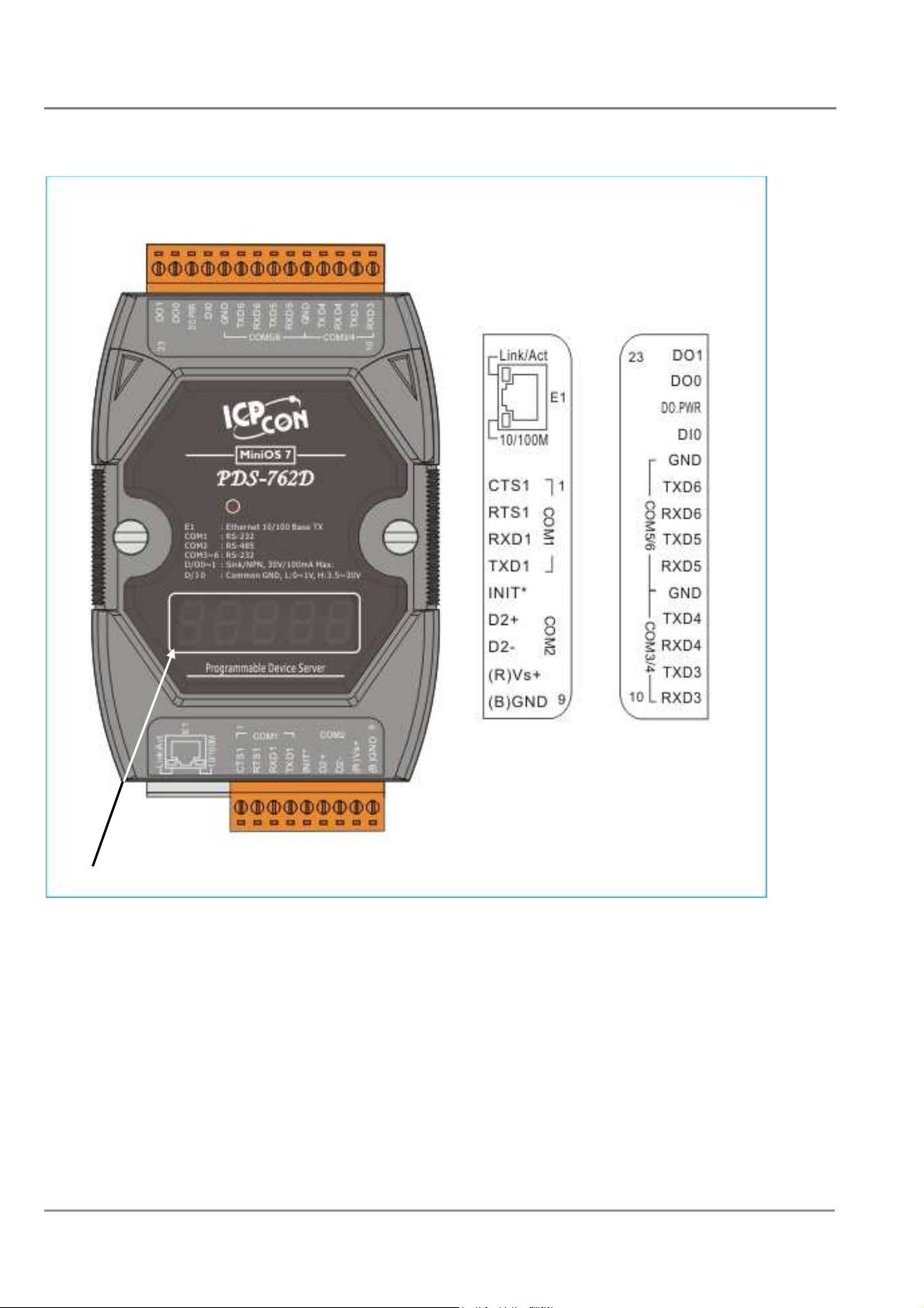
PDS-762(D)/PPDS-762(D)-MTCP Pin Assignments
Only D-version modules have a 5-digit 7-SEG LED.
PDS Series User Manual ( V1.4, Oct. 2009) ----- 52
Page 53
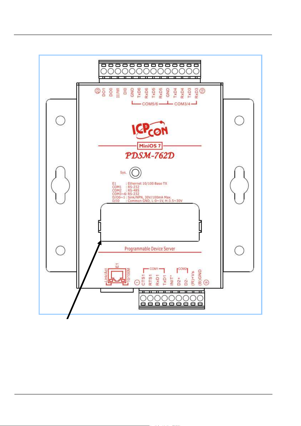
PDSM-762(D)/PPDSM-762(D)-MTCP Pin Assignments
Only D-version modules have a 5-digit 7-SEG LED
PDS Series User Manual ( V1.4, Oct. 2009) ----- 53
Page 54
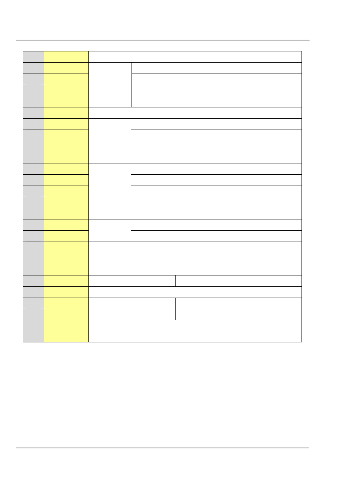
Pin
Name Description
1 CTS1 CTS pin
2 RTS1 RTS pin
3 RXD1 RXD pin
4 TXD1
COM1
(RS-232)
TXD pin
5 INIT* Initialization pin (for enabling/disabling AUTOEXEC.BAT)
6 D2+ Data+ pin
7 D2-
COM2
(RS-485)
Data- pin
8 VS+ V+ pin for the power supply (+10 ~ +30 VDC unregulated)
9 GND GND pin for the power supply (COM1 GND)
10 RXD3 RXD pin
11 TXD3 TXD pin
12 RXD4 RXD pin
13 TXD4
COM3
(RS-232)
TXD pin
14 GND GND pin for COM3/COM4
15 RXD5 RXD pin
16 TXD5
17 RXD6 RXD pin
18 TXD6
COM5
(RS-232)
COM6
(RS-232)
TXD pin
TXD pin
19 GND GND pin for COM5/COM6
20 DI0 Digital Input channel 0 3.5 V ~ 30 V
21 DO.PWR Power Input for Digital Output
22 DO0 Digital Output channel 0
100 mA, 30 V max.
23 DO1 Digital Output channel 1
1. 10/100 Base-TX
- E1
2. PoE (IEEE 802.3af, Class 1)_Only for PoE version
PDS Series User Manual ( V1.4, Oct. 2009) ----- 54
Page 55
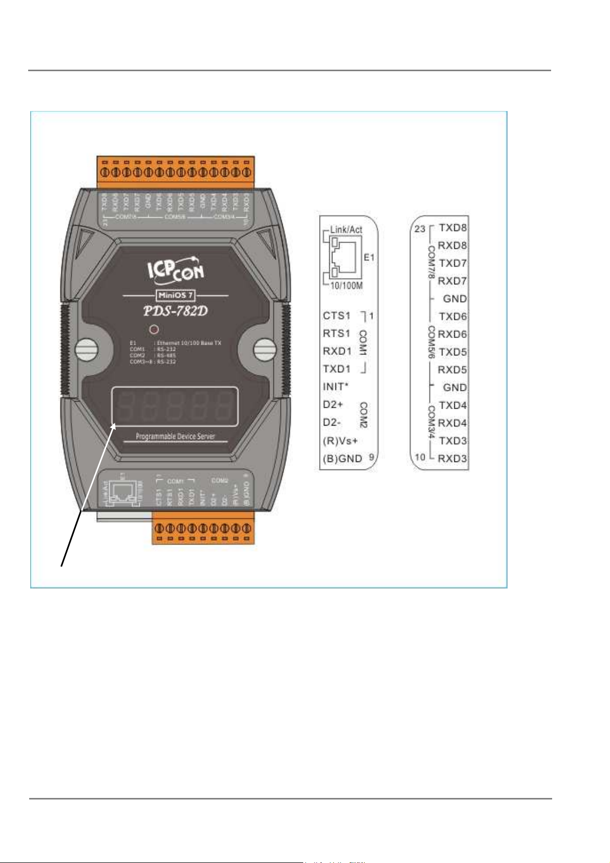
PDS-782(D)/PPDS-782(D) Pin Assignments
Only D-version modules have a 5-digit 7-SEG LED.
PDS Series User Manual ( V1.4, Oct. 2009) ----- 55
Page 56
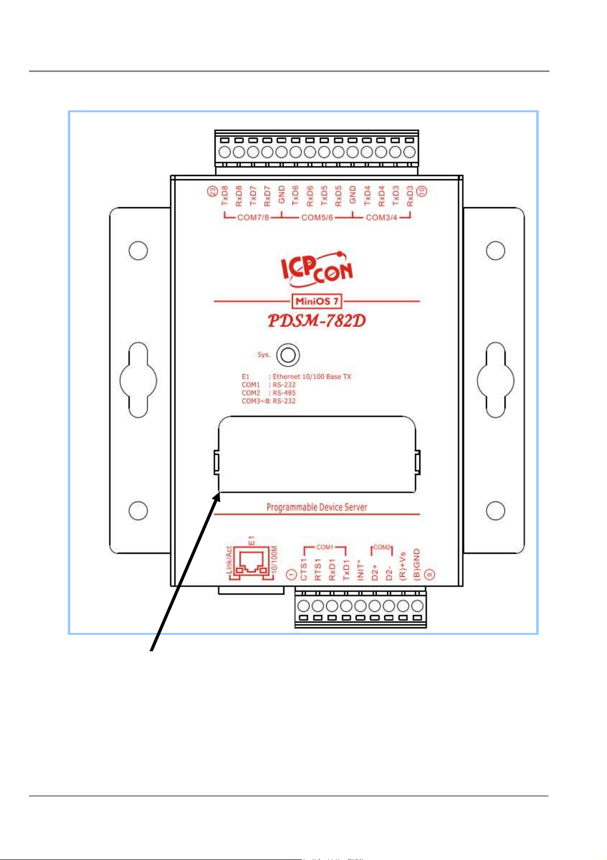
PDSM-782(D)/PPDSM-782(D) Pin Assignments
PDS Series User Manual ( V1.4, Oct. 2009) ----- 56
Page 57
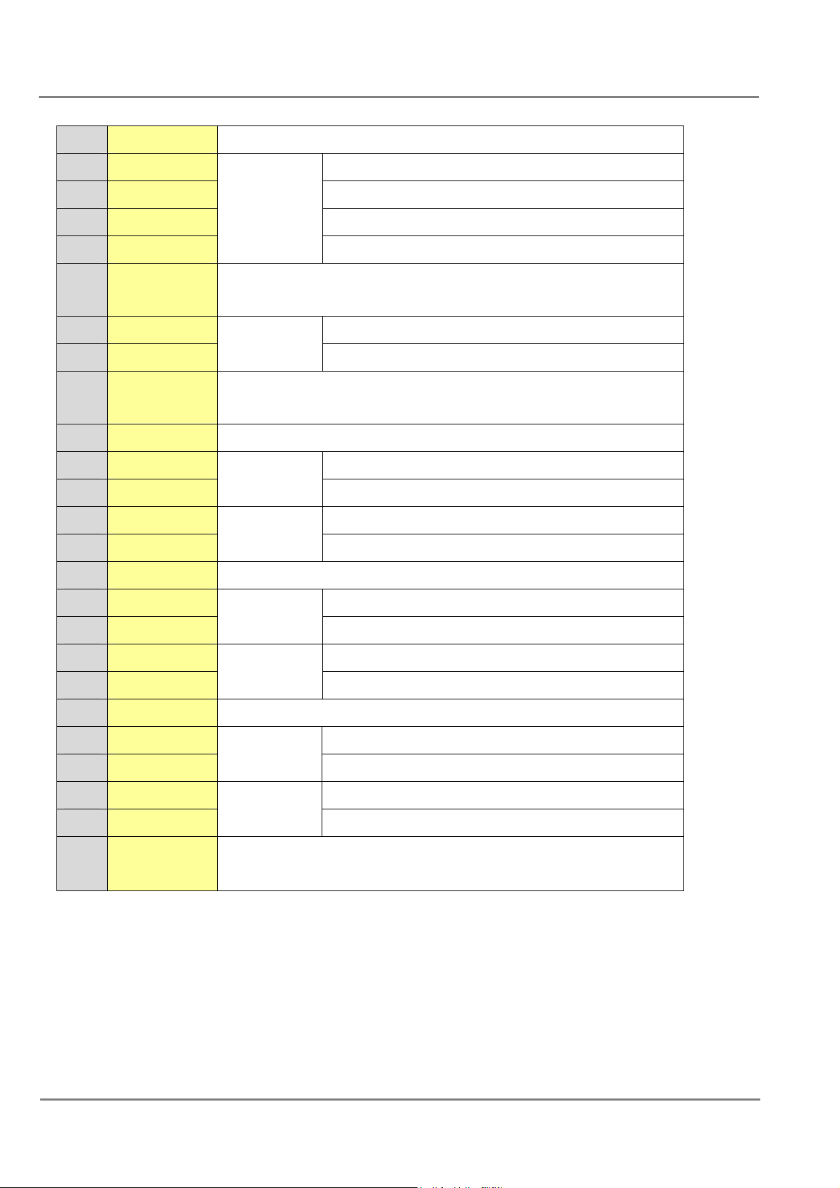
Pin Name Description
1 CTS1 CTS pin
2 RTS1 RTS pin
3 RXD1 RXD pin
4 TXD1
COM1
(RS-232)
TXD pin
5 INIT* Initialization pin (for enabling/disabling
AUTOEXEC.BAT)
6 D2+ Data+ pin
7 D2-
COM2
(RS-485)
Data- pin
8 VS+ V+ pin for the power supply (+10 ~ +30 VDC
unregulated)
9 GND GND pin for the power supply (COM1 GND)
10 RXD3 RXD pin
11 TXD3
12 RXD4 RXD pin
13 TXD4
COM3
(RS-232)
COM4
(RS-232)
TXD pin
TXD pin
14 GND COM3/COM4/COM5/COM6 GND pin
15 RXD5 RXD pin
COM5
16 TXD5
17 RXD6
18 TXD6
(RS-232)
COM6
(RS-232)
TXD pin
RXD pin
TXD pin
19 GND COM5/COM6/COM7/COM8 GND pin
20 RXD7 RXD pin
21 TXD7
22 RXD8 RXD pin
23 TXD8
COM7
(RS-232)
COM8
(RS-232)
TXD pin
TXD pin
- E1 1. 10/100 Base-TX
2. PoE (IEEE 802.3af, Class 1)_Only for PoE version
PDS Series User Manual ( V1.4, Oct. 2009) ----- 57
Page 58
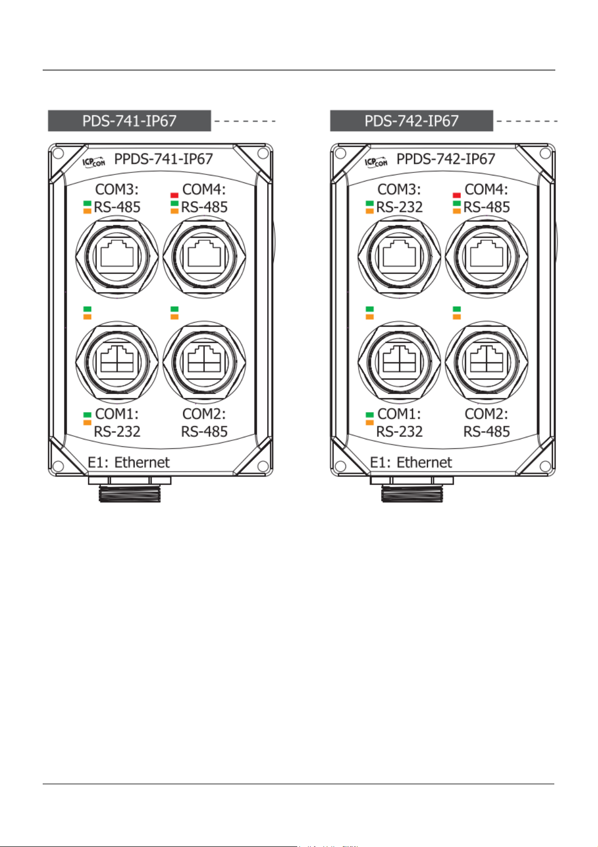
PDS-700-IP67
PDS Series User Manual ( V1.4, Oct. 2009) ----- 58
Page 59
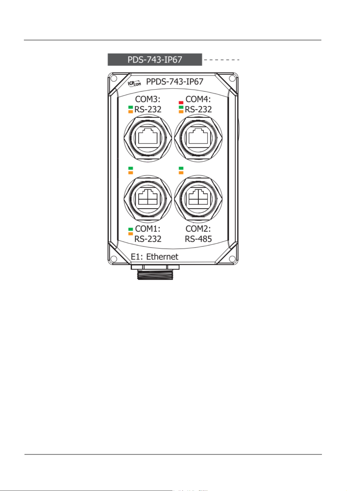
PDS Series User Manual ( V1.4, Oct. 2009) ----- 59
Page 60
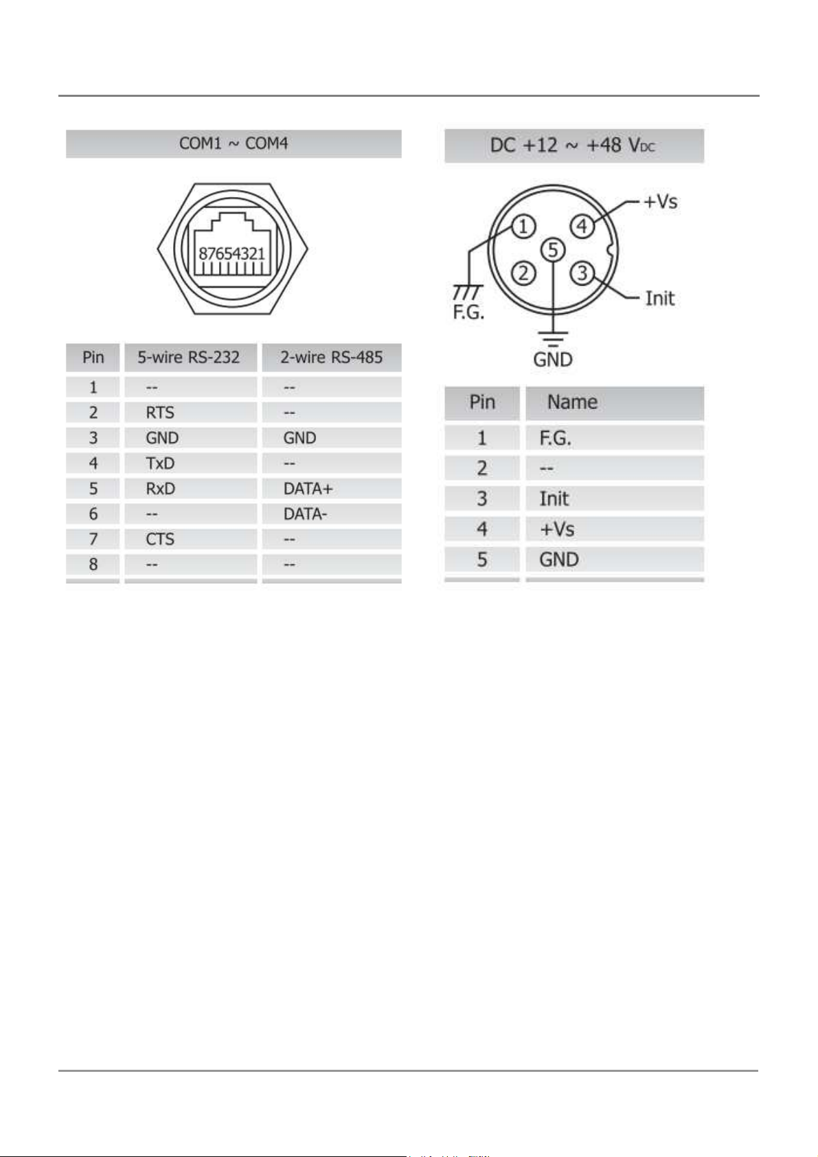
PDS Series User Manual ( V1.4, Oct. 2009) ----- 60
Page 61
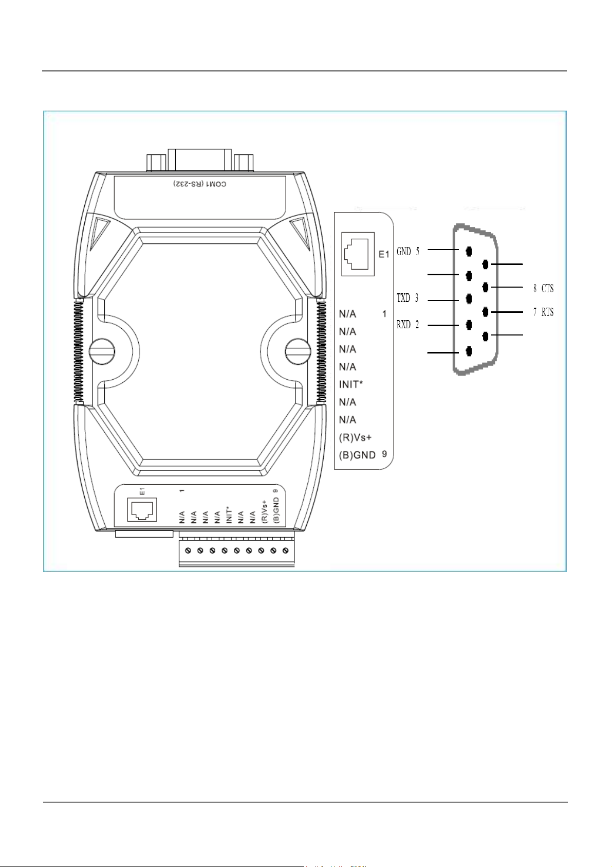
DS-712/PPDS-712-MTCP Pin Assignments
E1: 10/100 Base-TX
PDS Series User Manual ( V1.4, Oct. 2009) ----- 61
Page 62
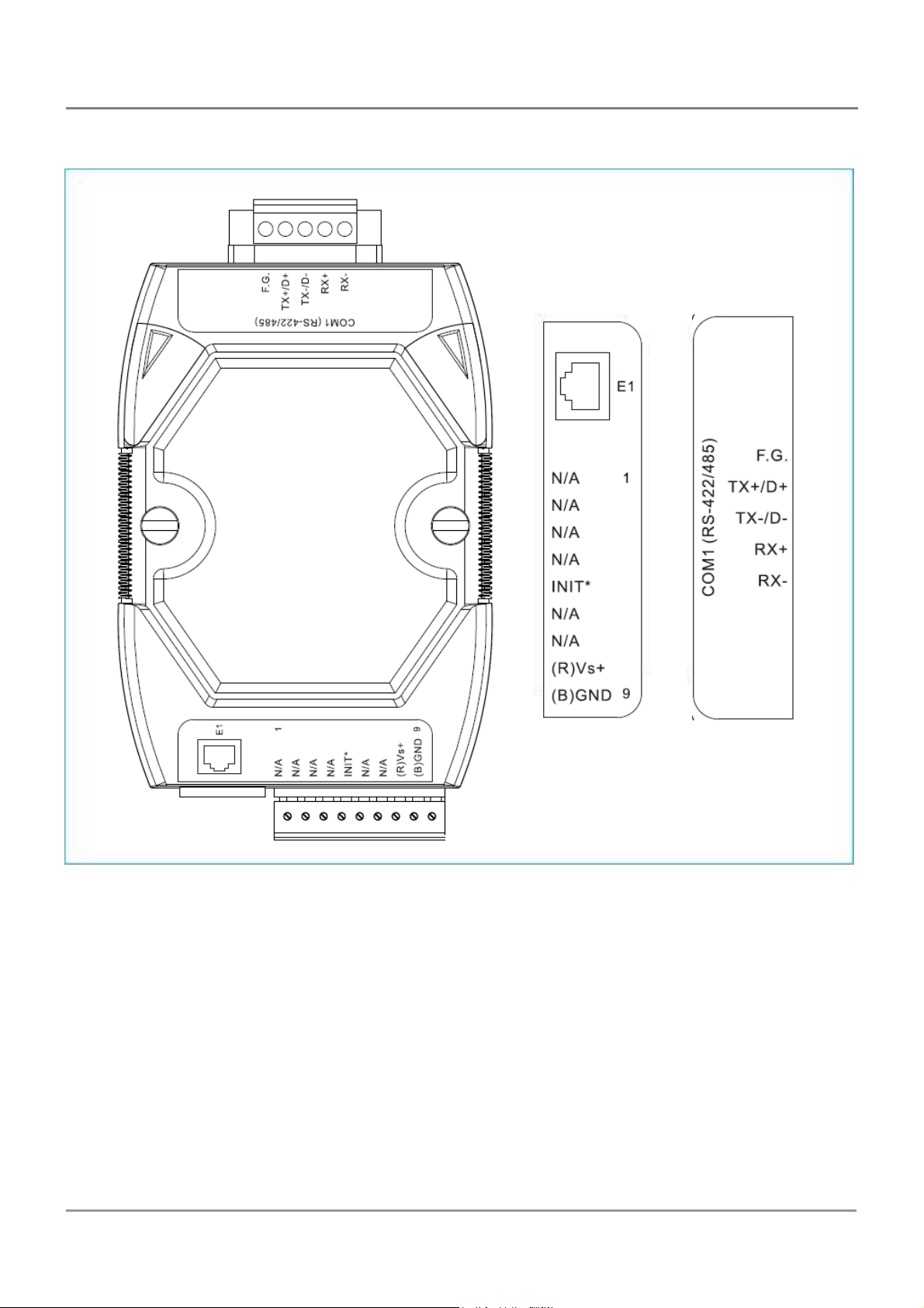
DS-715/PPDS-715-MTCP Pin Assignments
E1: 10/100 Base-TX
PDS Series User Manual ( V1.4, Oct. 2009) ----- 62
Page 63
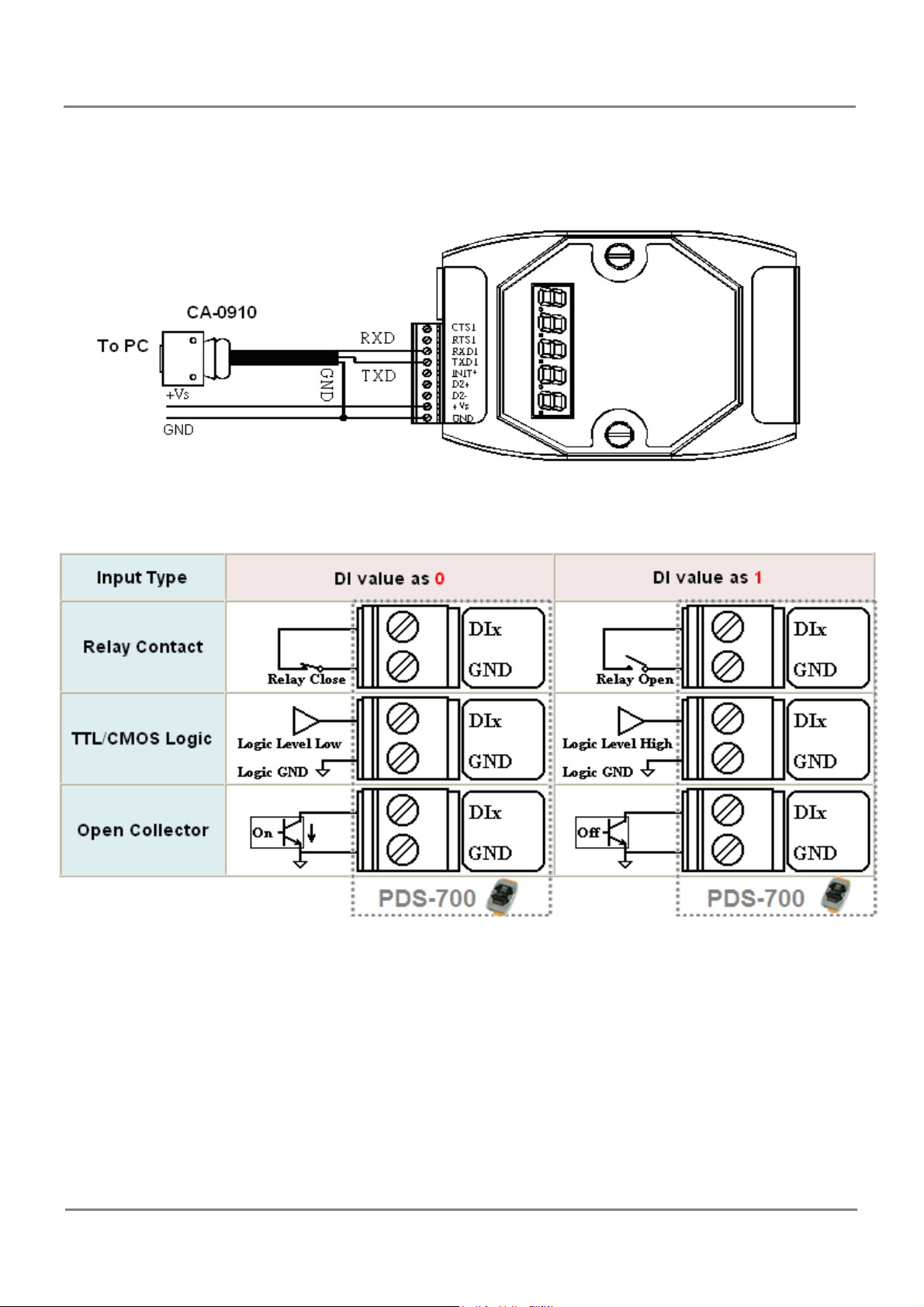
3.5. PDS Wiring Connections
COM1: The COM1 GND-signal is shared with pin9, GND
Digital Input
PDS Series User Manual ( V1.4, Oct. 2009) ----- 63
Page 64
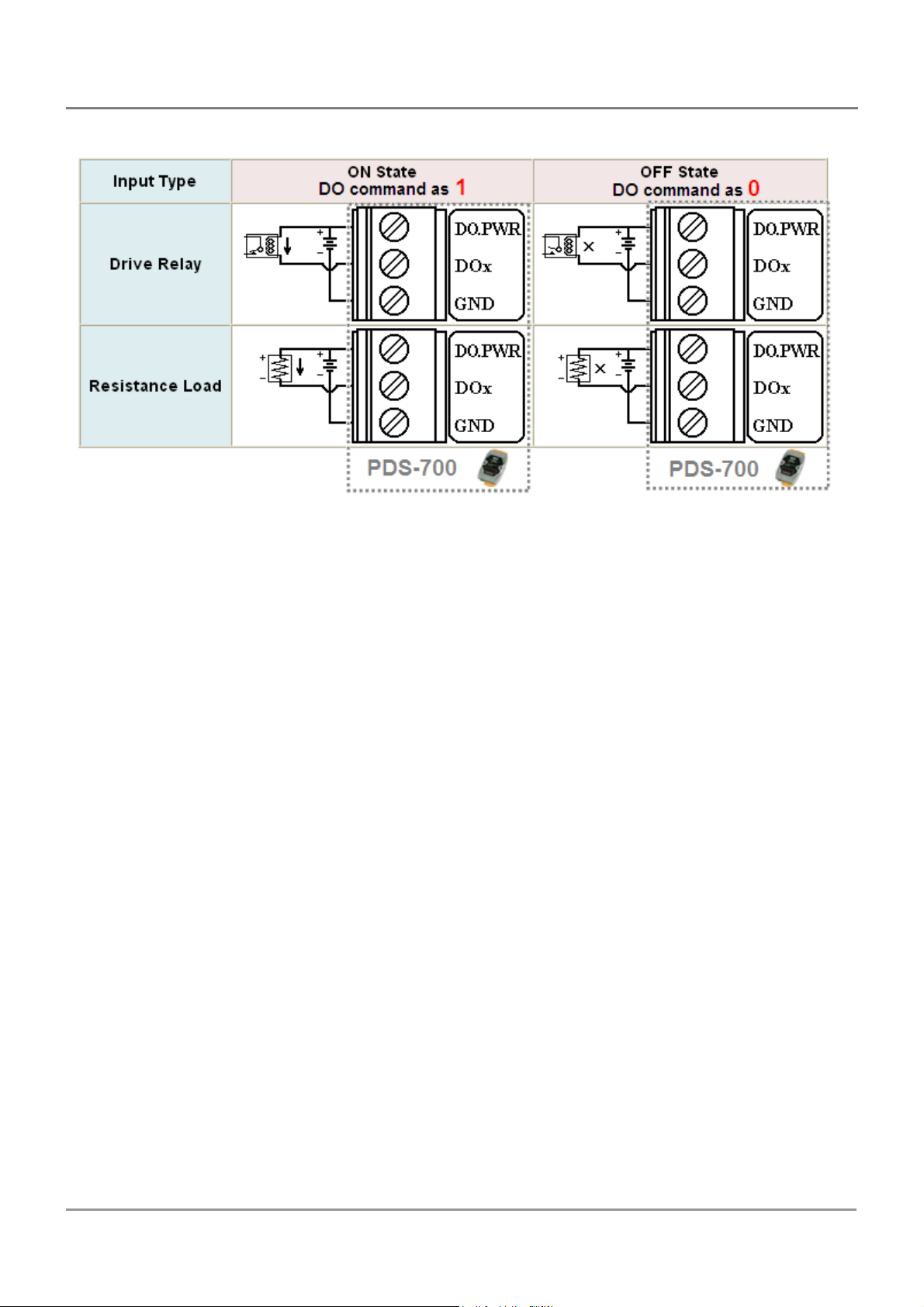
Digital Output
PDS Series User Manual ( V1.4, Oct. 2009) ----- 64
Page 65

3.6. Dimensions and Mounting
PDS-700/PPDS-700-MTCP
q
Top View
Bottom View
Front View
Din-Rail Mounting Bracket
Back View
PDS Series User Manual ( V1.4, Oct. 2009) ----- 65
Unit: mm
Side View
Page 66
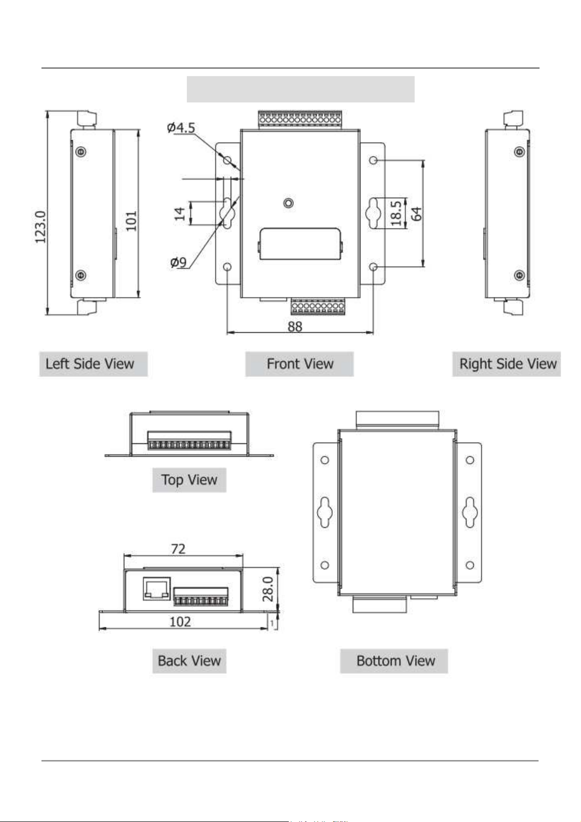
PDSM-700/PPDSM-700-MTCP
PDS Series User Manual ( V1.4, Oct. 2009) ----- 66
Page 67
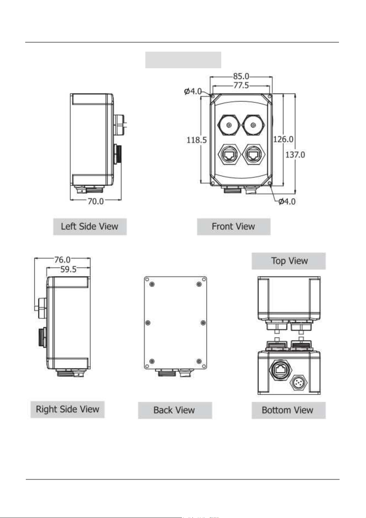
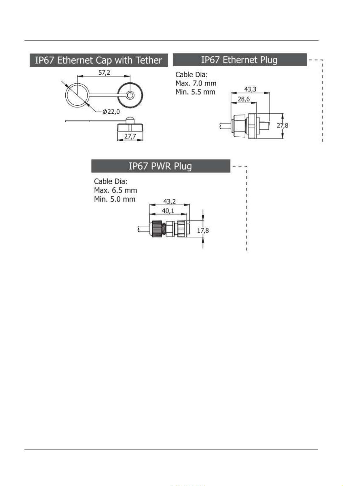
PPDS-700-IP67
PDS Series User Manual ( V1.4, Oct. 2009) ----- 67
Page 68
PDS Series User Manual ( V1.4, Oct. 2009) ----- 68
Page 69
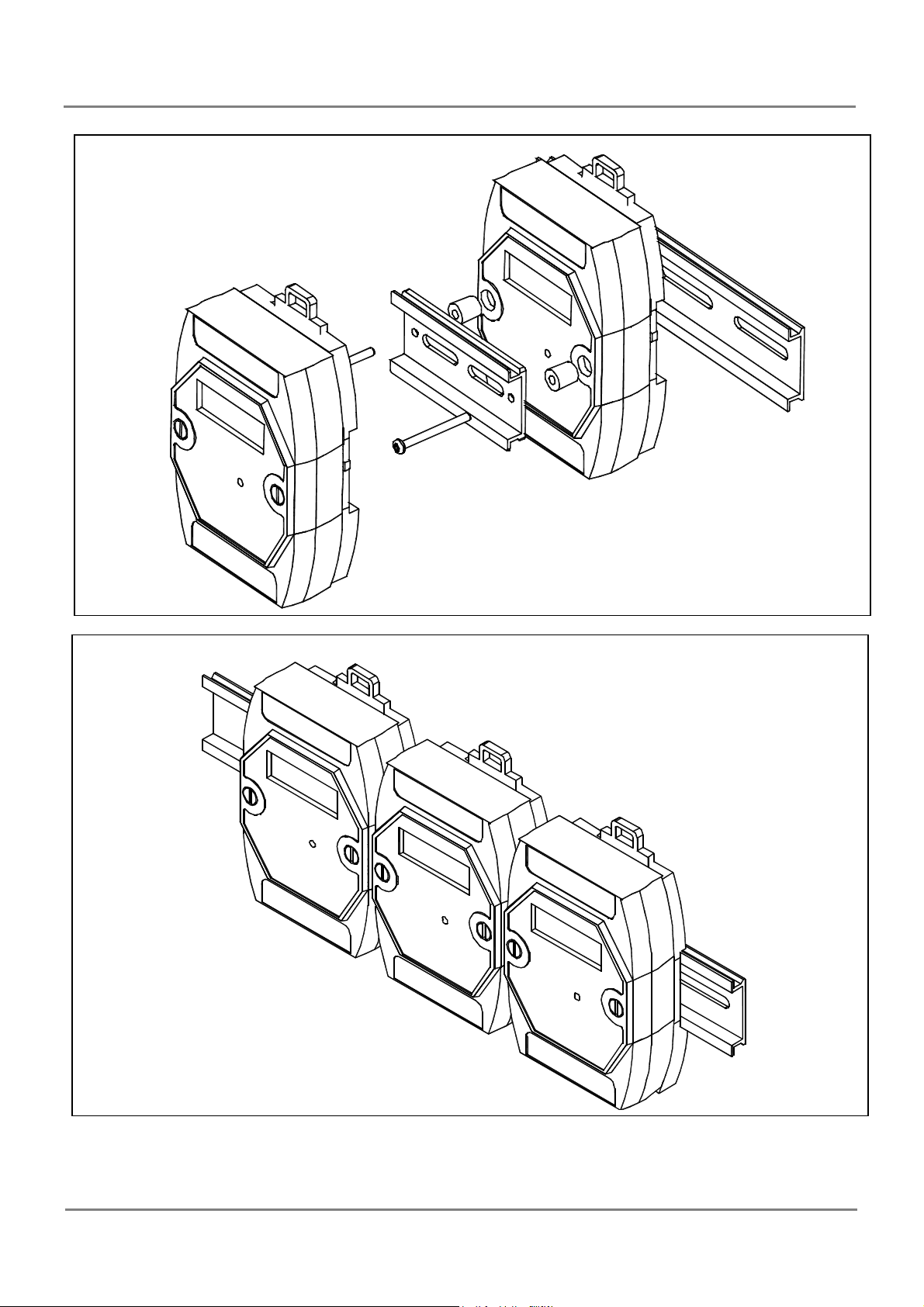
Stack Mounting
Din-Rail Mounting
PDS Series User Manual ( V1.4, Oct. 2009) ----- 69
Page 70
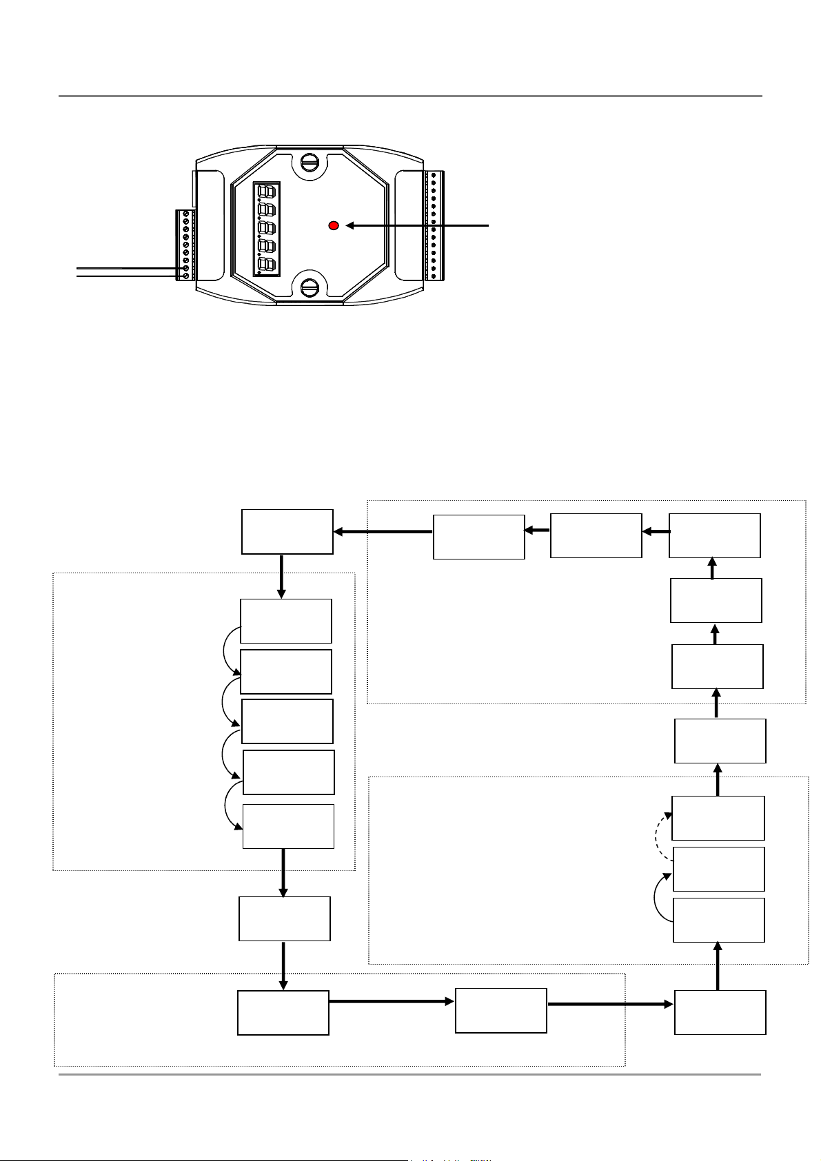
parity, stop
= 1
Stop
= 1
supply can range from +12 V ~ +48 V.
3.7. PDS series Diagnostics
CTS1
RTS1
RXD1
TXD1
INIT*
D2+
+Vs
GND
Step1: Apply power (+Vs, GND) to the PDS. PDS(M)-700 power supply can range from
+10 V ~ +30 V. PPDS(M)-700-MTCP, DS-700, PPDS-700-IP67, PDS-782-25 power
Step2: Check the 5-digit 7-SEG LED. Data will be shown as follows.
D2+Vs
GND
Note: Only D-version modules have a 5-digit 7-SEG LED.
Indicator LED
VxComm running: On/Off
Xserver running: On/Off
The IP address
is 192.168.255.1
11111.
1. 192
2. 168
3. 255
4. 1
10000
22222.
5.00.01
4.00.00
Connected clients and
debugging information
COM8: data = 8, odd
COM2: data = 7, even
parity, stop = 2
COM1: data = 8, no parity,
3.00.00
2.0000
1.26.00
44444.
8. 821
2. 712
1. 8n1
1. 96
COM1 Baud Rate = 9600
PDS Series User Manual ( V1.4, Oct. 2009) ----- 70
2. 96
COM2 Baud Rate = 9600
33333.
Page 71

Information related to the PDS series module can be classified into 4 main areas:
Group ID 11111: The IP address information for the PDS-700
Group ID 22222: The Baud Rate for all COM Ports
Group ID 33333: The COM Port configuration
Group ID 44444: The Connected clients and debugging information for this PDS series
module
The format for the PDS IP address information is as follows:
5-Digit LED Group ID: 11111
LED -1: indicator, which can be either 1, 2, 3 or 4
LED -2~5: IP address
TCP command port (Default = 10000)
DHCP Setting: disabled (0)/enabled (1)
The LED will initially display the Group ID, and will then display the IP address as
illustrated in the previous diagram. If the IP address is changed, the value displayed will
change immediately. The default shipping IP is 192.168.255.1 and the display sequence is
shown in the previous diagram.
The format for the COM Port Baud Rate information is follows:
5-Digit LED Group ID : 22222
LED-1: COM Port number
LED-2~5: The Baud Rate determined as (Baud Rate/100)
LED-1 displays the COM Port number, with LED-2~5 showing the Baud Rate for that
COM Port. The Baud Rate = (value shown by LED-2~5) * 100. Therefore, a COM Port
value displayed as 1.96 means that the Baud Rate of COM1 = 9600 bps; a value displayed
as 2.1152 means that the Baud Rate of COM2 = 115200 bps. The Baud Rates for all PDS
COM Ports will be shown in sequence.
PDS Series User Manual ( V1.4, Oct. 2009) ----- 71
Page 72

The format for the COM Port configuration information is as follows:
5-digit LED Group ID: 33333
LED-1: COM Port number
LED-3: Data Bit: 5 , 6 , 7 or 8
LED-4: Parity Bit, n = no parity, E = even parity, O = odd parity
M = mark parity, S = space parity
LED-5: Stop Bit: 1 or 2
The format for the connected clients and debugging information is as follows:
5-digit LED Group ID: 44444
LED-1 will display 1, 2, 3, 4, 5 and the module name in sequence.
When LED-1 is 1, LED-2/3 indicates the number of available free sockets (default is
26 for PDS), and LED-4/5 shows the number of sockets being used by clients (default
is 0), e.g. 12600
When LED-1 is 2, LED-2~5 indicates how many times the PDS has been reset, e.g.
20002 (The PDS-700 has been reset 2 times)
When LED-1 is 3, the display indicates how many Ethernet packets are currently being
received by the PDS.
When LED-1 is 4, the display indicates that the status of the internal Flag used to
allow Ethernet packets to be sent is 0 or 1.
When LED-1 is 5, the display indicates the number of times the Ethernet chip has been
reset.
Module Name: dS.7xx
When the PDS is first powered-up or if it has just been reset, the reset state = 1. If any
client connects to the PDS, the reset state will be changed to 0. In addition, the number of
free sockets will be decreased and the number of used sockets will be increased. If the
number of free sockets is reduced to 0, then no additional clients will be able to link to the
PDS. The default number of free-sockets for the PDS is 26. Therefore, the server
(VxComm firmware or Xserver firmware) allows 26 connections to be linked to a single
PDS. Each client program occupies at least 2 connections for a single serial port, one
connection for data and another for commands.
PDS Series User Manual ( V1.4, Oct. 2009) ----- 72
Page 73
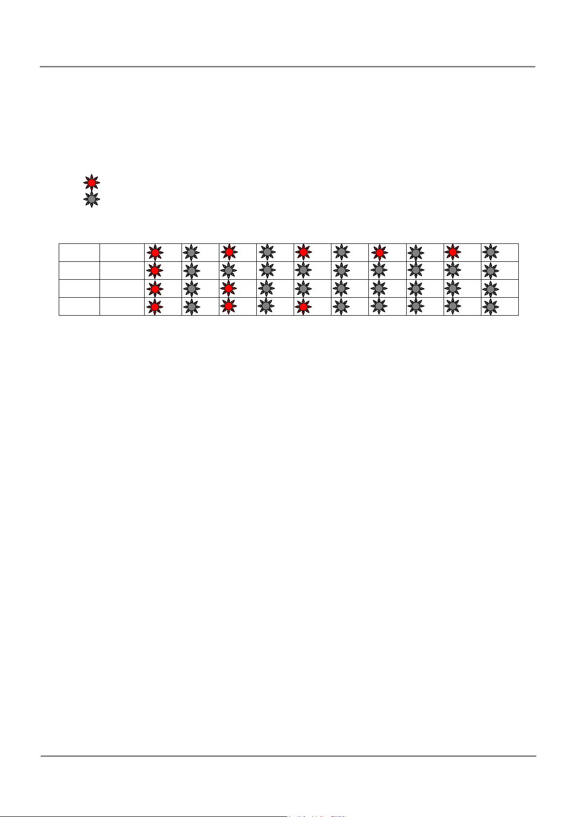
If the 5-digit LEDs do not display the above detail, take the following steps:
Power off the module
Connect the INIT* pin to the VS+ pin
Power on the module and double check the configuration
Step 3: The red LED on the PDS is used to indicate the following:
ON
OFF
Unit 0.5 second
OS
M0
M1
M2
The PDS contains either Xserver or VxComm as default when shipped that is in the
OS mode.
If the LED is always ON, take the following steps:
Power off the module
Connect the INIT* pin to the VS+ pin
Power on the module and double check the configuration
Step 4: Power off the module.
PDS Series User Manual ( V1.4, Oct. 2009) ----- 73
Page 74

4. Setting up the PDS module
Step 1: Connect the PDS module to the Ethernet Network
Before connecting the PDS module to an Ethernet network, the following items are
needed:
1. Power Supply:10 ~ 30 VDC (for PDS(M)-700)
12 ~ 48 V
25)
(eg:DP-665:http://www.icpdas.com/products/Accessories/power_supply/power_list.htm )
2. Hub (eg:NS-205http://www.icpdas.com/products/Switch/industrial/industrial_list.htm )
3. The network settings in the PC are correctly configured and the Ethernet connection is
(for PPDS(M)-700-MTCP, DS-700, PPDS-700-IP67, PDS-782-
DC
functioning normally.
4. Disable or correctly configure the Windows firewall and any Anti-Virus software
firewall first or else the “Search Servers” function in the VxComm Utility may not work.
(Contact your System Administrator for more details of how to do this.)
5. Connect the PDS series module to the Ethernet as shown on the following page and
switch on the power.
6. Make sure the indicator LED is flashing.
If your PDS series module is a D-version module, the 5-digit 7-SEG LED will be used
to indicate the system information described in Sec. 3.7
7. Install VxComm Utility on your PC
The software is located at:
CD: \NAPDOS\ Driver\VxComm_Driver
http://ftp.icpdas.com/pub/cd/8000cd/napdos/driver/vxcomm_driver/
PDS Series User Manual ( V1.4, Oct. 2009) ----- 74
Page 75
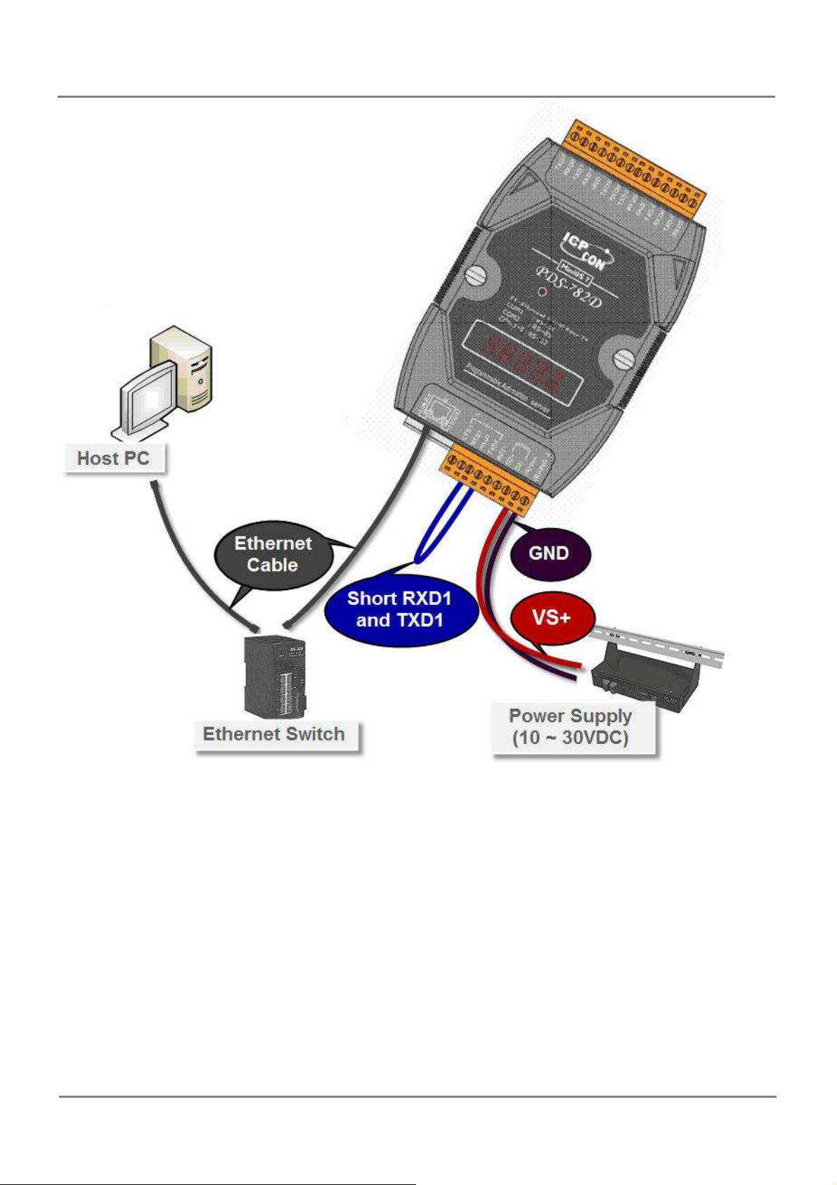
Connect the PDS series module and your computer to the same sub network or the
same Ethernet Switch.
Short the RXD1 and TXD1 pins of the PDS series module for execute a self-test.
Supply 24 VDC (10 ~ 30 VDC) power to the PDS(W)-700 module.
Supply 24 VDC (12 ~ 48 VDC) power to the PPDS(W)-700-MTCP, DS-700, PPDS-
700-IP67, PDS-782-25 module.
PDS Series User Manual ( V1.4, Oct. 2009) ----- 75
Page 76
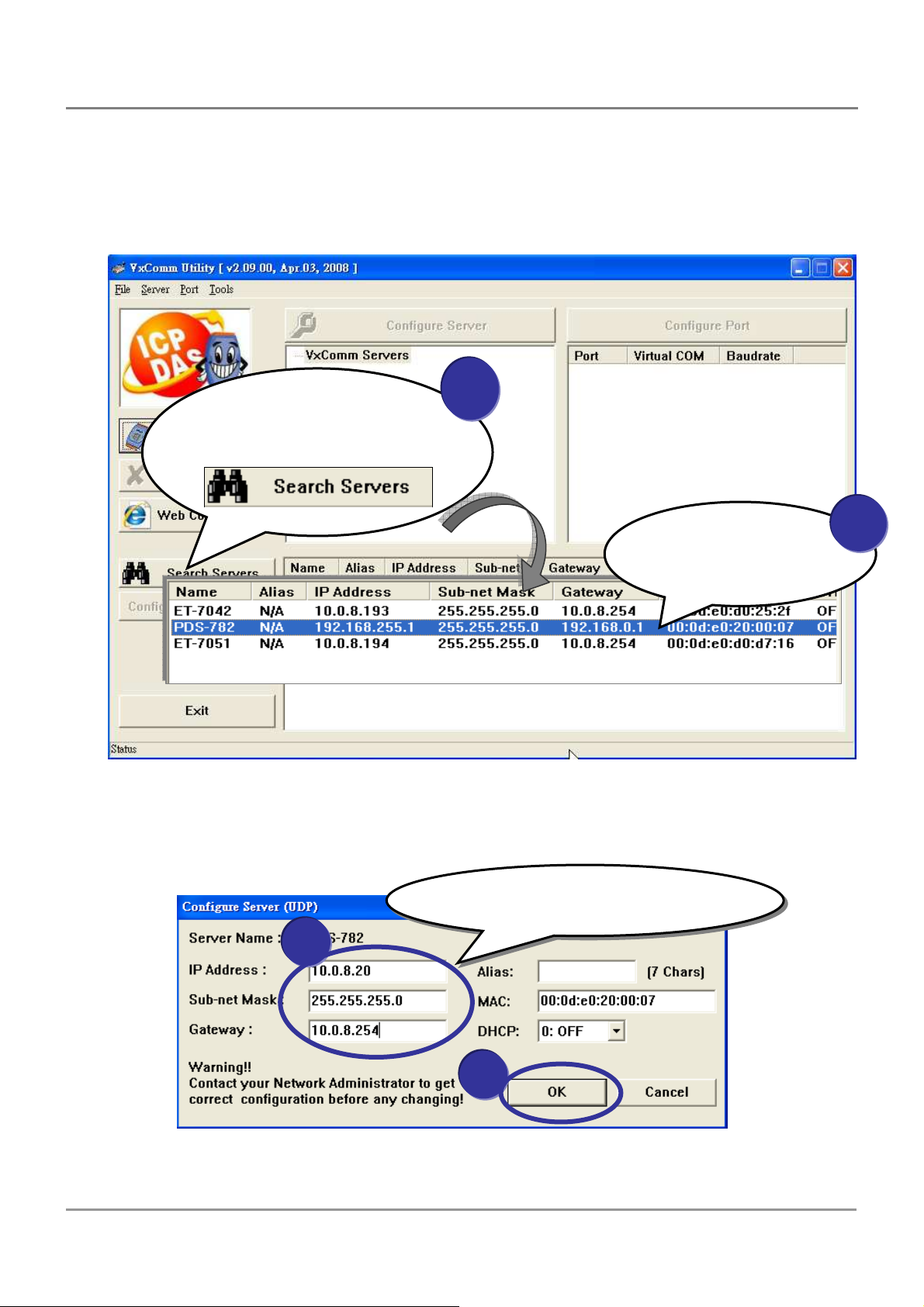
IP Address, Sub
-
net Mask,
Step 2: Search for the PDS series module on the Ethernet network
1. Execute the VxComm Utility and then search for your PDS series module.
2. Double click the name of the PDS to open the configuration settings dialog box.
Click the “Search Severs”
button to search for your
PDS
1
Double click the
name of your
2
PDS
3. Contact your Network Administrator to obtain the correct network configuration details
(such as IP/Mask/Gateway). Enter the network settings and then click “OK”. The PDS
series module will be restarted itself immediately.
Configure the Ethernet settings
1
PDS Series User Manual ( V1.4, Oct. 2009) ----- 76
2
Page 77
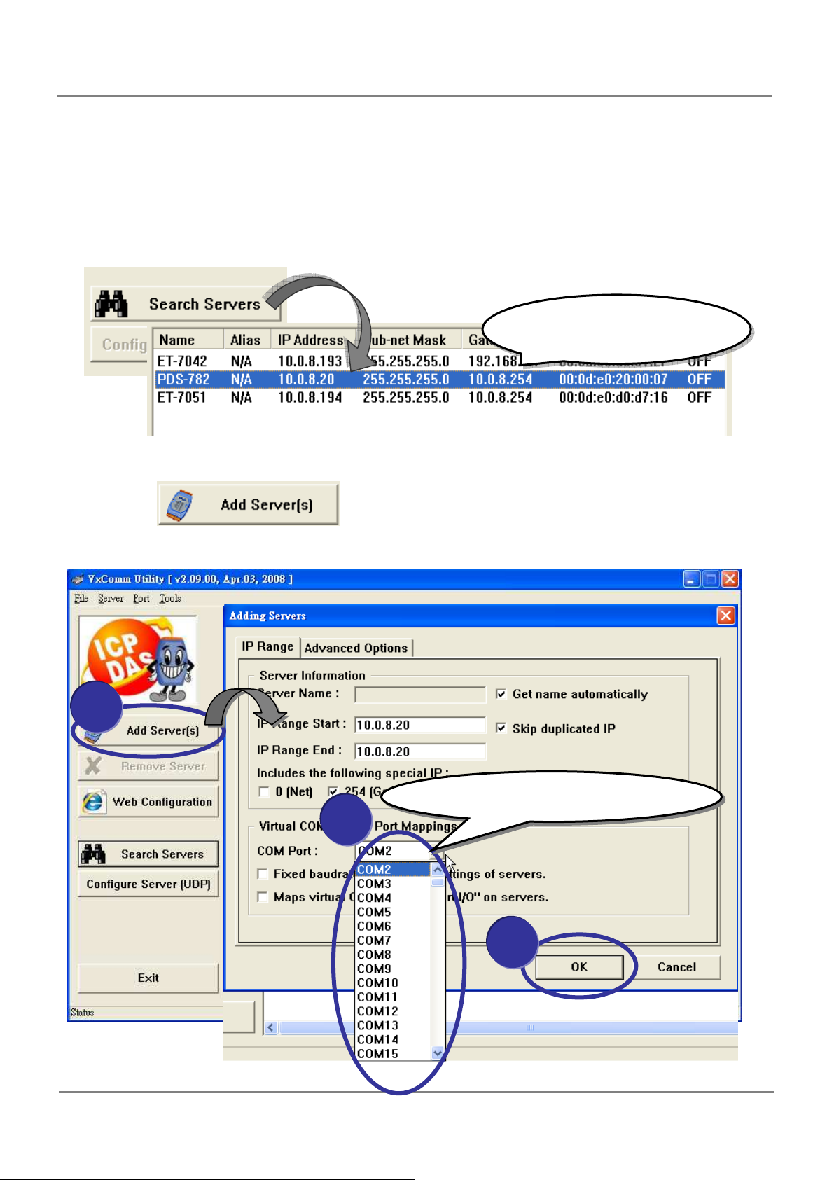
your PDS
-
700
module
Step 3: Configuring Virtual COM Ports
1. Click the “Search Servers” button again to search for your PDS series module to make
sure that the new IP/Mask/Gateway settings have been saved, then click the name of
your PDS series module once to select it.
Click the name of
2. Click the button, then assign a COM Port number and click
“OK” to save your settings.
1
Assign a COM Port number
2
3
PDS Series User Manual ( V1.4, Oct. 2009) ----- 77
Page 78
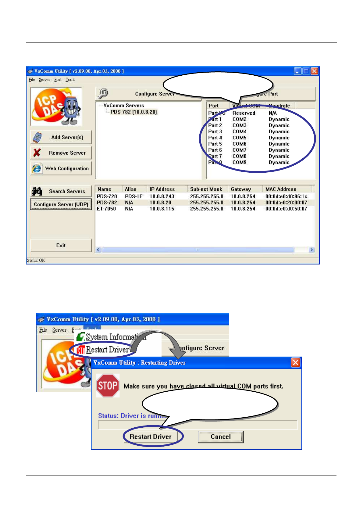
3. Check the Virtual COM port numbers on the PC.
Check the COM Port
5. Click “Restart Driver” from the “Tools” menu, and then click the “Restart Driver”
button to start the driver.
Click the ”Restart Driver”
button to start the driver
PDS Series User Manual ( V1.4, Oct. 2009) ----- 78
Page 79

Step4: Testing your PDS
1. Connect the “RXD1” and the “TXD1” of the PDS series module, as shown in the
diagram in Step1.
2. Right click Port 1 and then choose the “Open COM Port” option.
3. Check that the configuration of the COM Port is correct and then click the “Open
COM” button.
Check that the configuration is correct
and then click the “Open COM” button
PDS Series User Manual ( V1.4, Oct. 2009) ----- 79
Page 80
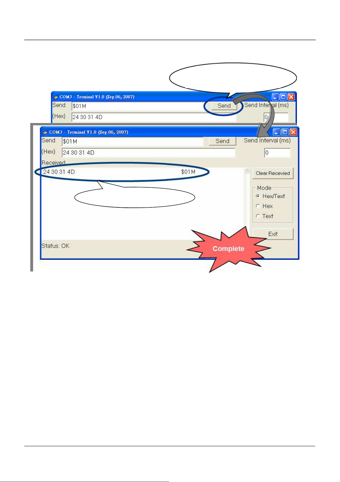
4. Type a string in the send field then click the send button. If a response is received, it
will be displayed in the received field.
Click “Send” to send a string
to your PDS series module
The response is displayed
5. If the test is successful, the COM port program will be able to work directly by setting
the Virtual COM Port number.
PDS Series User Manual ( V1.4, Oct. 2009) ----- 80
Page 81
5. Configuration with Web Browser
Once the PDS series module has been correctly configured and is networking normally,
the configuration details can be retrieved or amended using either the VxComm Utility or
a standard web browser, such as IE, FireFox, or Mozilla, etc.
5.1. Connecting to the PDS Series Module
If the COM port program is operating with a PDS, changing the
configuration will cause a program error.
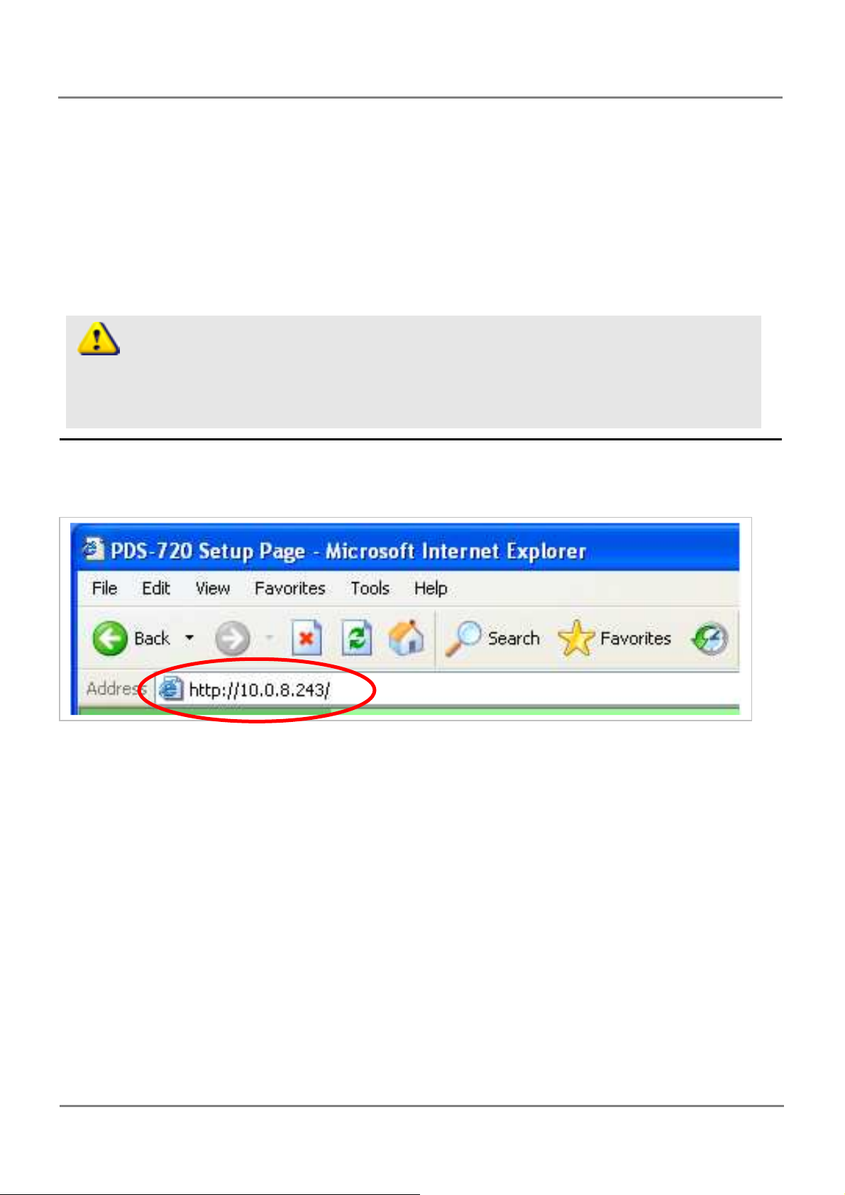
Enter the IP address of the PDS series module in the Address field and press “Enter” to
connect to the PDS series module.
PDS Series User Manual ( V1.4, Oct. 2009) ----- 81
Page 82
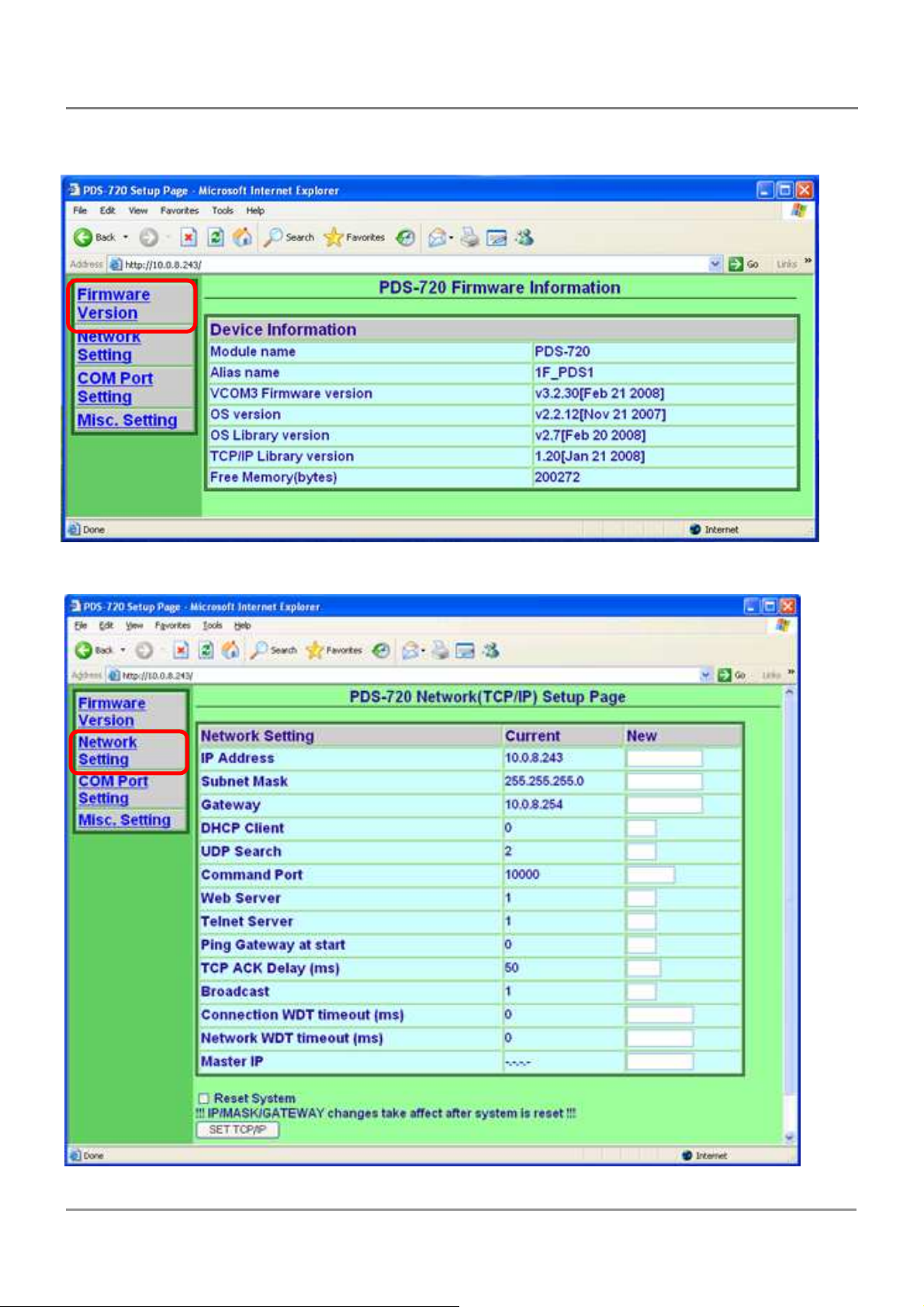
When the browser connects to the PDS, the first page that will be display is the
Firmware Information page.
5.2. Network Settings
PDS Series User Manual ( V1.4, Oct. 2009) ----- 82
Page 83

Network (TCP/IP) Setup page
IP Address
Subnet Mask
Gateway
The above three items are the most important network settings and should always
correspond to the LAN definition. If they do not match, the PDS series module will not
operate correctly. If the settings are changed while the module is operating, any links to
Virtual COM Port based applications currently in use will be lost and an error will occur.
DHCP Client : 0 = disabled, 1 = enabled
It is recommended that the DHCP Client setting is kept as disabled, and using static
network settings. This ensures your PDS always using a fixed IP address, and you don’t
need to configure the virtual COM mappings again and again.
UDP Search: 0 = disabled, 1 = always enabled.
2 = enable the UDP Search function until another client is connected. (Default = 2)
By keeping the UDP search setting as 2, the PDS loading will be reduced. The
VxComm Utility will not be able to search for this module until this module’s clients are
all disconnected.
Command Port
The default Command Port is 10000.
Web Server
Telnet Server
0 = disabled, 1 = enabled
Ping Gateway at start: 0 = disabled, 1 = enabled.
If the setting is 1 (enabled), the PDS series module will send a ping packet to the
gateway during the power-on stage. It is used to inform the gateway that a PDS (itself) has
joined the network.
TCP ACK Delay (ms), default = 50.
PDS does not want to send an empty ACK followed by a TCP data packet 1ms later,
every time. So it delays a little (TCP ACK Delay), and then can combine the ACK and
data packet into one. This efficiency reduces the number of packets and reduces network
loadings.
PDS Series User Manual ( V1.4, Oct. 2009) ----- 83
Page 84
Broadcast
1 = receive UDP broadcast packets
0 = reject UDP broadcast packets
Connection WDT timeout (ms): default = 0 (disabled), min. = 10000.
If the PDS series module does not receive any data from a client PC within the period
of the “Connection WDT timeout”, the module will close the connection to the client.
Network WDT timeout (ms): 0 = disabled, min. = 30000.
If the PDS series module does not receive any data from any of the clients within the
period of the “Network WDT timeout”, the module will reboot itself. The default setting
should be 300000ms (= 300 seconds).
This setting is the same as “SystemTimeout” setting (unit: ms) on Console/Telnet
command, and is the same as “/STxxx” in command line parameter (unit: seconds).
When user uses “config=RESET” Console/Telnet command to clear the EEPROM,
the “Network WDT timeout” (SystemTimeout, /ST) setting will also be cleared to 0.
Users have to configure this setting again by “SystemTimeout” Console/Telnet
command.
Master IP: default = empty (disabled).
If the Master IP is set, only the client using Master IP can change the COM Port
configuration. It is to prevent the COM Port configuration changed by other clients.
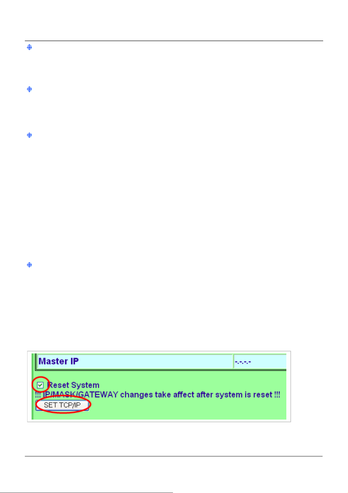
After setting the new configuration, click the “Set TCP/IP” button to save the new
settings to the PDS series module. If the “Reset System” option is checked, the PDS series
module will reboot itself after the saving operation is complete, otherwise the original
settings will still be valid until the next power-on.
PDS Series User Manual ( V1.4, Oct. 2009) ----- 84
Page 85
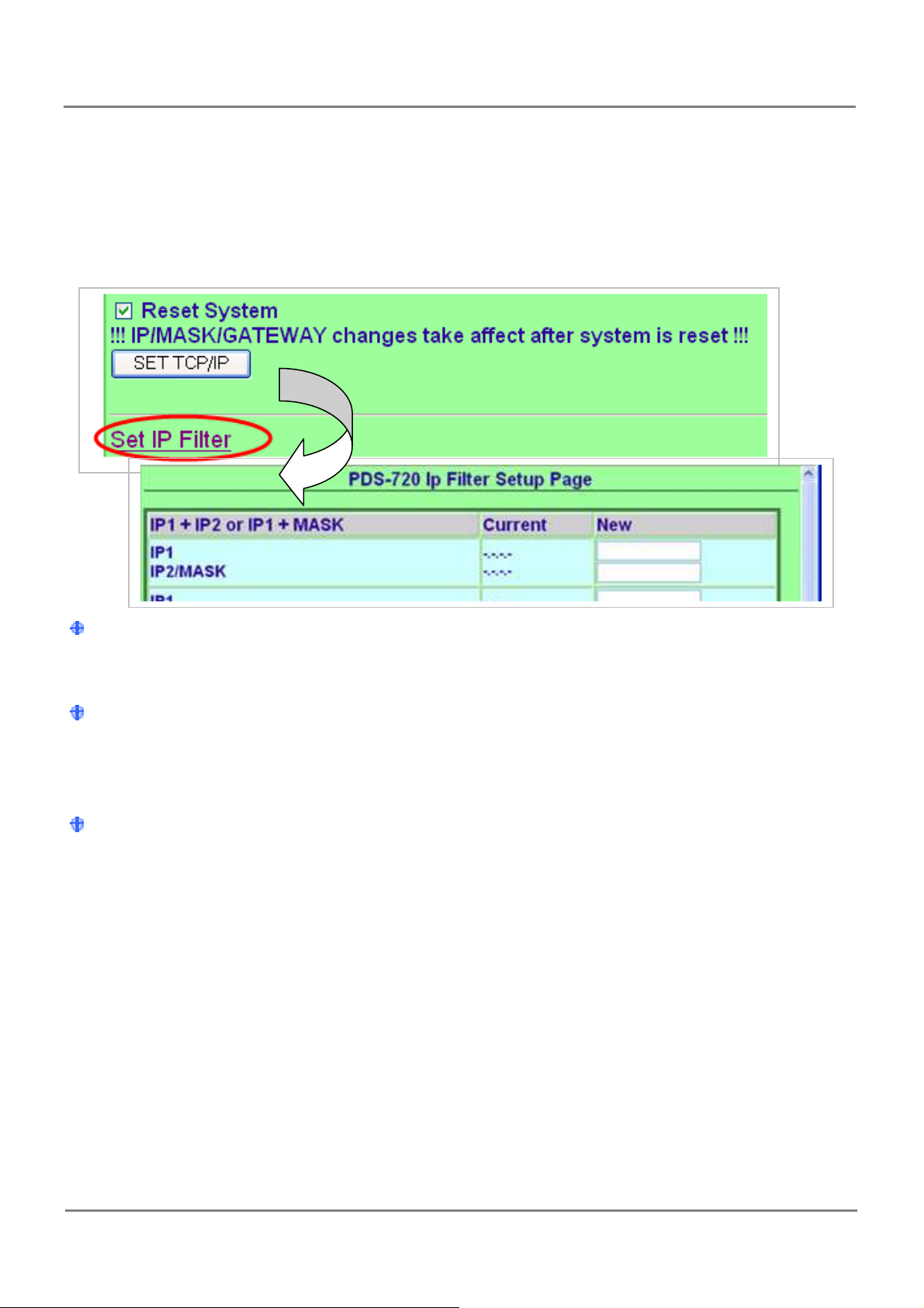
5.3. IP filter setting
The IP filter setting limits which client PCs are able to link to the PDS series module
via specific IP addresses. When one or more IP addresses are set in the filter table, only
client PCs where the IP address is included in the range listed of the filter table will be
able to connect to the PDS series module. Any requests from other PCs will be rejected
Set IP1 only: only clients who’s IP address is included in the filter table are able to
connect to the PDS series module.
Set IP1 + IP2: set a range of IP address as a starting and ending point. The setting
allows clients who’s IP address is included in the range are able to connect to the PDS
series module.
Set IP1+Mask: set the IP filter range as:
(IP1 & Mask) + 0 ~ (IP1 & Mask) + (~Mask).
Only clients who’s IP address is included in the range are able to connect to the PDS
series module. For instance:
IP1 = 10.0.9.5, mask = 255.255.255.0
IP1 & MASK = 10.0.9.0, ~mask = 0.0.0.255
This allows clients who’s IP address is included in the range of 10.0.9.0 ~ 10.0.9.255
are able to connect to the PDS series module.
PDS Series User Manual ( V1.4, Oct. 2009) ----- 85
Page 86
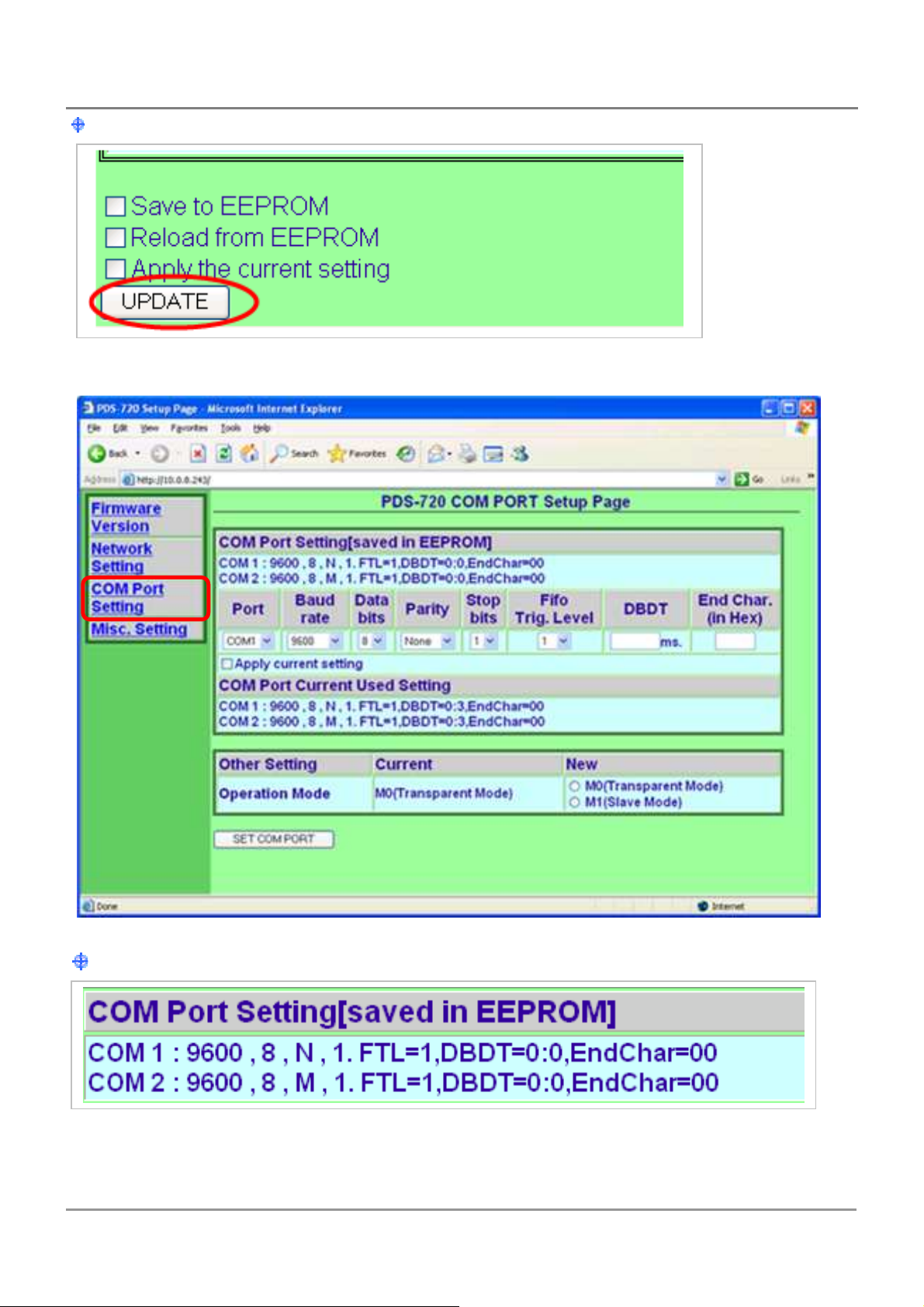
Click the “Update” button to validate the settings.
5.4. COM Port Settings
The COM Port Settings list is saved in the EEPROM on the PDS series module.
PDS Series User Manual ( V1.4, Oct. 2009) ----- 86
Page 87
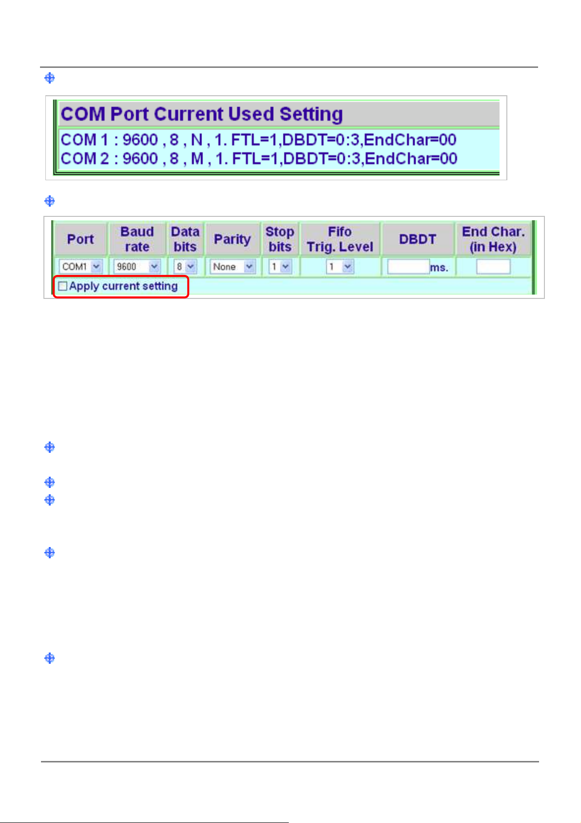
The Currently Used COM Port Settings list
The COM Port Settings area
Note: If the “Set COM Port” button is clicked without checking “Apply current setting”,
option the new settings will be saved to the PDS only and the new settings will be valid
after the next power-on.
If the “Apply current setting” checked when the “Set COM Port” button is clicked, the
new settings will be valid immediately.
Port: The COM Port number on the PDS series module.
Baud Rate, Data Bits, Parity
Stops Bits, End Character:
The configuration settings should match the serial device used.
Fifo Trig. Level: FIFO trigger level
This option is used to set the number of characters that the COM Port can receive at
once time, the PDS will move the data from the COM Port FIFO to the PDS. If the amount
of data transferred is large and uses a transfer speed (115200 bps), setting a smaller value
is helpful in preventing data loss.
DBDT (ms): Data buffer delay timeout
When the COM port does not receive data from devices connected over the period of
DBDT setting, the PDS will determine that the data transfer is over and return to process
next tasks.
PDS Series User Manual ( V1.4, Oct. 2009) ----- 87
Page 88
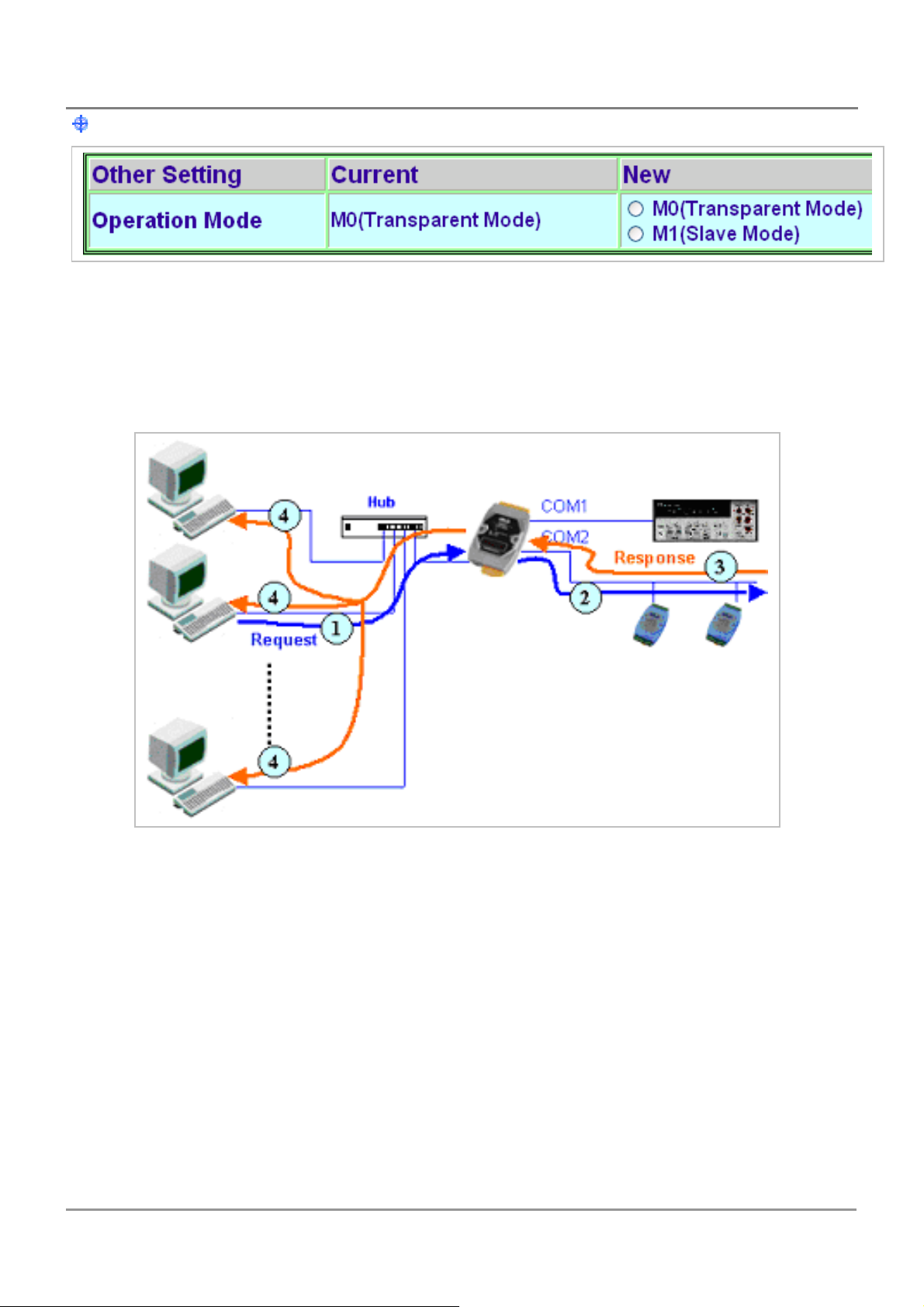
Other settings: M0 mode
M0: Transparent Mode (Multi-echo mode)
Condition 1: One client sends a request to the PDS series module to access each device.
The PDS series module echoes the data from each device to each connected
client
PDS Series User Manual ( V1.4, Oct. 2009) ----- 88
Page 89
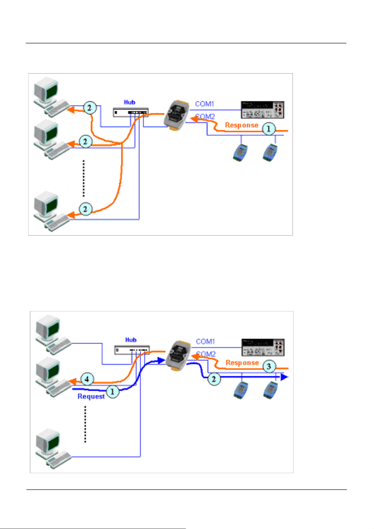
Condition 2: No clients send any requests to the PDS series module. The PDS series
module echoes data from the devices to each connected client.
M1: Slave Mode (Single-echo mode)
Condition 1: One client sends a request to the PDS series module to access the other
devices. The PDS series module echoes data from the devices to the client that requested
the service.
PDS Series User Manual ( V1.4, Oct. 2009) ----- 89
Page 90
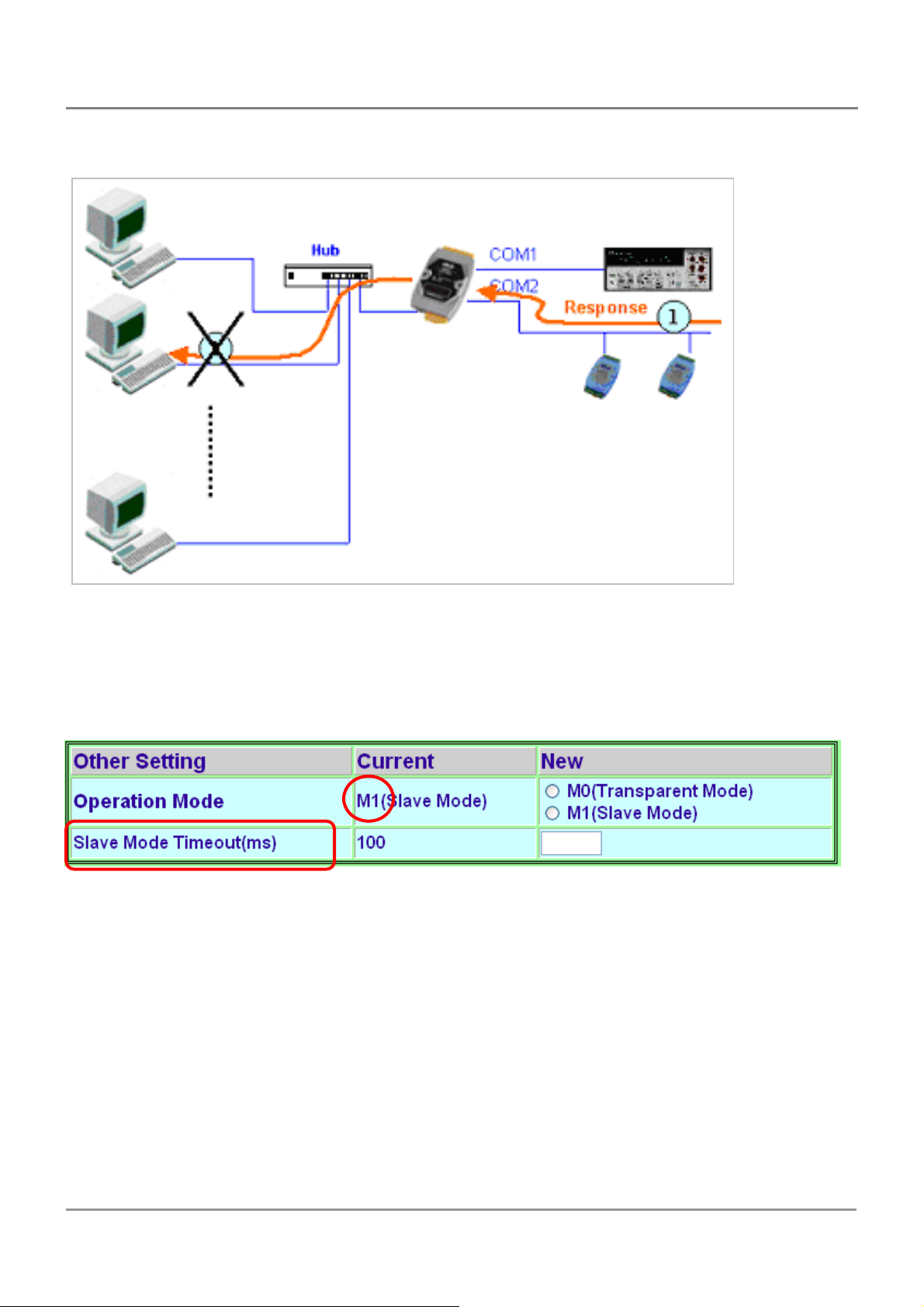
Condition 2: No clients send any requests to the PDS series module. The PDS series
module doesn’t echo any data from the devices to any client.
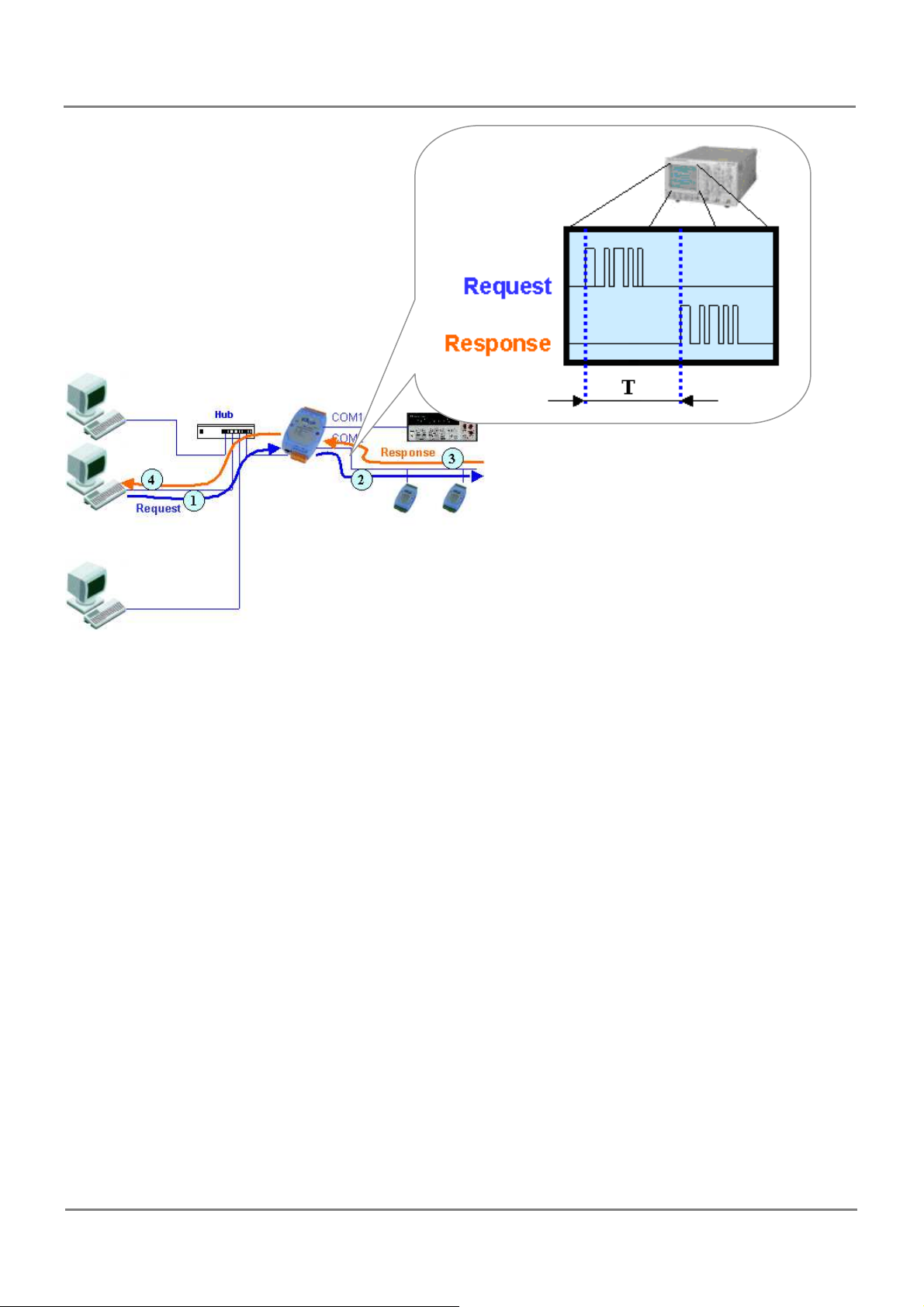
In M1, the slave mode timeout setting is use to set the waiting time after last character
of the request sent to the device. If the device does not respond within the timeout value,
the PDS series module will return a timeout error and process next request.
PDS Series User Manual ( V1.4, Oct. 2009) ----- 90
Page 91
PDS Series User Manual ( V1.4, Oct. 2009) ----- 91
Page 92
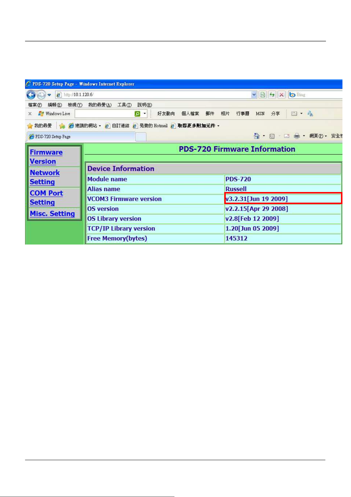
5.5. Pair Connection Setting?
1. Check your firmware version is later than v3.2.31[Jun 19 2009]
PDS Series User Manual ( V1.4, Oct. 2009) ----- 92
Page 93
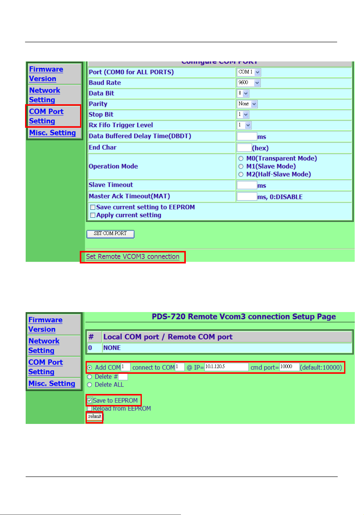
2. Click “Set Remote VCOM3 connection” on the COM PORT setting page.
3. Select “Add COM” and type in the number of the local COM port to use.
4. And type in the number of the remote COM port, IP and cmd port.
5. Check the “Save to EEPROM” and click “submit” button.
6.
Reboot the local PDS to activate pair connection
.
PDS Series User Manual ( V1.4, Oct. 2009) ----- 93
Page 94

5.6. Miscellaneous settings
Alias Name: allocates an alias to the PDS series module.
Web Read Only: 0 = disabled, 1 = enabled
If the “Web Read Only” properly is set to 1, enabled, the web server will not
be able to save any new configurations to the PDS series module. To disable the
“Web Read Only” property, refer to the information below.
Login: used to disable the “Web Read Only” property or to set a new password.
1. Enter the password (default is admin) and click the “LOGIN” button to proceed to the
settings page.
PDS Series User Manual ( V1.4, Oct. 2009) ----- 94
Page 95
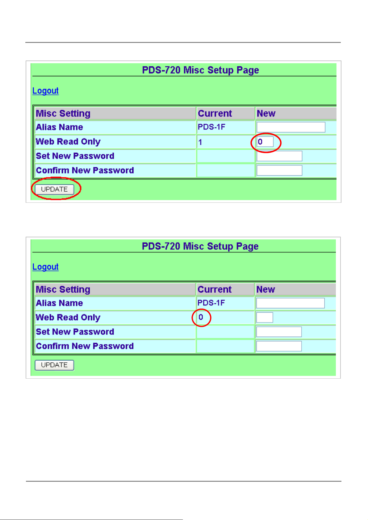
2. Set the new “Web Read Only” properly = 0 and click the “UPDATE” button.
3. Check that the current the “Web Read Only” = 0 and then click “Logout” to complete
the operation.
4. User can restore PDS password to default value “admin” by using “config=RESET”
console command (refer to section Console/Telnet Commands List). This command sets
most configurations of PDS to factory setting. It requires rebooting the PDS for loading
new configuration (includes default password).
PDS Series User Manual ( V1.4, Oct. 2009) ----- 95
Page 96
6. Modbus Testing & Protocol
Step 1: Install Modbus Utility on your PC
The software is located at:
CD: \ Napdos\Modbus\Modbus_Utility
http://ftp.icpdas.com/pub/cd/8000cd/napdos/modbus/modbus_utility/
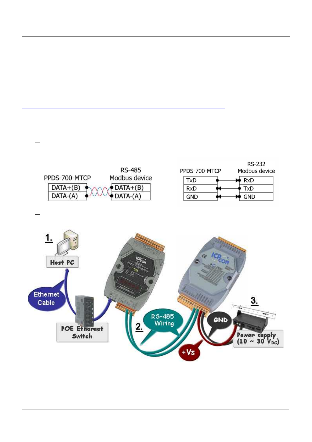
Step 2: Connecting the Modbus device to PPDS(M)-700(D)-MTCP
1. Keep up network connection status for your PPDS-700-MTCP.
2. Connect the Modbus device (Ex: M-7015) to PPDS-700-MTCP on COM2 (RS-
485 bus).
3. Supply power to the Modbus device (Ex: M-7015, Default ID: 1).
PDS Series User Manual ( V1.4, Oct. 2009) ----- 96
Page 97
6.1. Modbus/TCP to Modbus/RTU Gateway
PPDS(M)-700(D)-MTCP series can work as a Modbus/TCP to Modbus/RTU gateway
that support most SCADA/HMI communications based on the Modbus/TCP protocol.
Step 1: Configuring COM Ports for Modbus Gateway
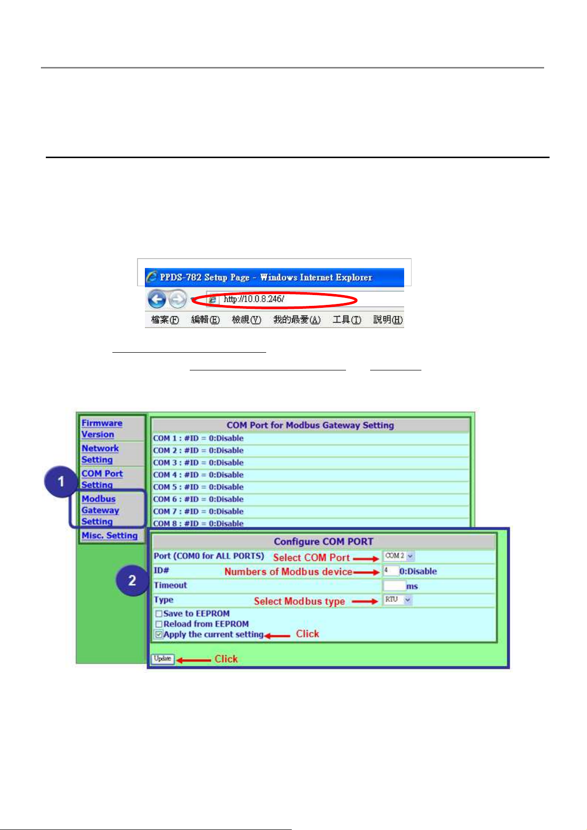
1.
Enter the IP address of the PPDS series module in the Address field and press “Enter”
to connect to the PPDS series module.
2. Click the "Modbus Gateway Setting" in the web page to configure the Modbus setting
for COM ports. Click the "Apply the current setting" and "Update" button to update it to
PPDS-700-MTCP.
- 97 -
Page 98
3. Check the COM Port for Modbus gateway setting.
Step 2: Test Modbus/TCP to Modbus/RTU Gateway
1. Run the Modbus Utility program and then click the Modbus/TCP button.
2. Click on Client tools Modbus/TCP Client .
PDS Series User Manual ( V1.4, Oct. 2009) ----- 98
Page 99
3. Enter the PPDS-700-MTCP IP address and then click the “Connect” button to connect
the PPDS-700-MTCP.
4. Refer to “Protocol Description” and type the command in the command field then click
the “Send Command” button. If the response data is correct, it means the test is success.
- 99 -
Page 100
6.2. Testing Modbus device through Virtual COM Ports
If want to use Modbus/RTU through Virtual COM Ports, you can refer to below steps.
Step 1: Configuring COM Ports for Virtual COM
1. Enter the IP address of the PPDS series module in the Address field and press “Enter”
to connect to the PPDS series module.
2. Make sure your COM Ports of PPDS(M)-700(D)-MTCP which aren’t in the M3 mode.
Select “COM Port Setting” in the web configuration and set the “Operation Mode”. Check
the “Apply current setting” and then click the “SET COM PORT” button to complete the
setting.
PDS Series User Manual ( V1.4, Oct. 2009) ----- 100
 Loading...