

Page 1

Installation Guide
10BASE-T/10BASE-FL
Ethernet Media Converter
NC-10TFT / NC-10TFC
-1- Version 1.0, Oct/2004
Page 2

Table of Contents
1. General Description………………………………………………P3
1.1 Specifications……………………………………………..…P3
2. Connectors & Cables……………………………………………..P4
2.1 10BASE-T UTP Cable……………………………………...P4
2.2 Fiber Optic Connector(Fiber Port)……………….………..P5
3. Installation………………………………………………………….P6
3.1 Install the media converter with the DC power supply…..P6
3.2 Making Network Connections………………………………P7
4. Interpreting LED Indicators………………………………………..P8
-2- Version 1.0, Oct/2004
Page 3

1 General Description
The NC-10TF Ethernet media converter series are designed to convert a
10BASE-T signal to a 10BASE-FL signal. It is used to extend the
connection distance between two Ethernet Twisted-pair devices via fiber
cable transparently with no performanve degradation.
1.1 Specifications
Comply with IEEE802.3 10BASE-T and 10BASE-FL std.
Provide a push button to set the crossover function for the TP port
Provide LEDs for easy network monitoring:
-Power status
-Link and receive status for TP port
-Link and receive status for fiber port
Fiber optic connectors:
-Multimode ST : (NC-10TFT)
-Multimode SC : (NC-10TFC)
0
Environment: Temperature 0-50
C
Humidity 10-90% non condensing
Dimensions : 26 x 150 x 125 mm (W x H x D)
Power : +10V~30VDC
Power comsumption : 3W
-3- Version 1.0, Oct/2004
Page 4

2 Connectors & Cables
10BASE-T RJ Connectors(TP Port)
One RJ-45 connector is provided on the converter for 10BASE-T
connection. For easy connection to any device using standard
straight-through UTP cable, a push button is available to set the crossover
function for the RJ-45.
RJ-45 Pin MDI-X Jack MDI Jack
1 RX+ TX+
2 RX- TX3 TX+ RX+
6 TX- RX-
2.1 10BASE-T UTP Cable
Cable : Category 3, 4, or 5 UTP
Maximum cable distance : 100 meters(328feet)
-4- Version 1.0, Oct/2004
Page 5

2.2 Fiber Optic Connector(Fiber Port)
The series provides different types of fiber connectors for different
applications. The connectors include multimode ST, multimode SC are
shown as follows :
The Wavelength used is 850nm. The series also support MM(multimode)
fiber cables. The recommended MM cable is 62.5/125µm.
Models
The following table lists the fiber connectors, fiber cables and the
maximum length supported by each converter model :
Model Connector Cable Used Cable Length*
NC-10TFT ST MM 2Km
NC-10TFC SC MM 2Km
*Cable length : the maximum length in point-to-point full duplex
operation
-5- Version 1.0, Oct/2004
Page 6

3 Installation
3.1 Install the media converter with the DC power supply
-6- Version 1.0, Oct/2004
Page 7
3.2 Making Network Connections
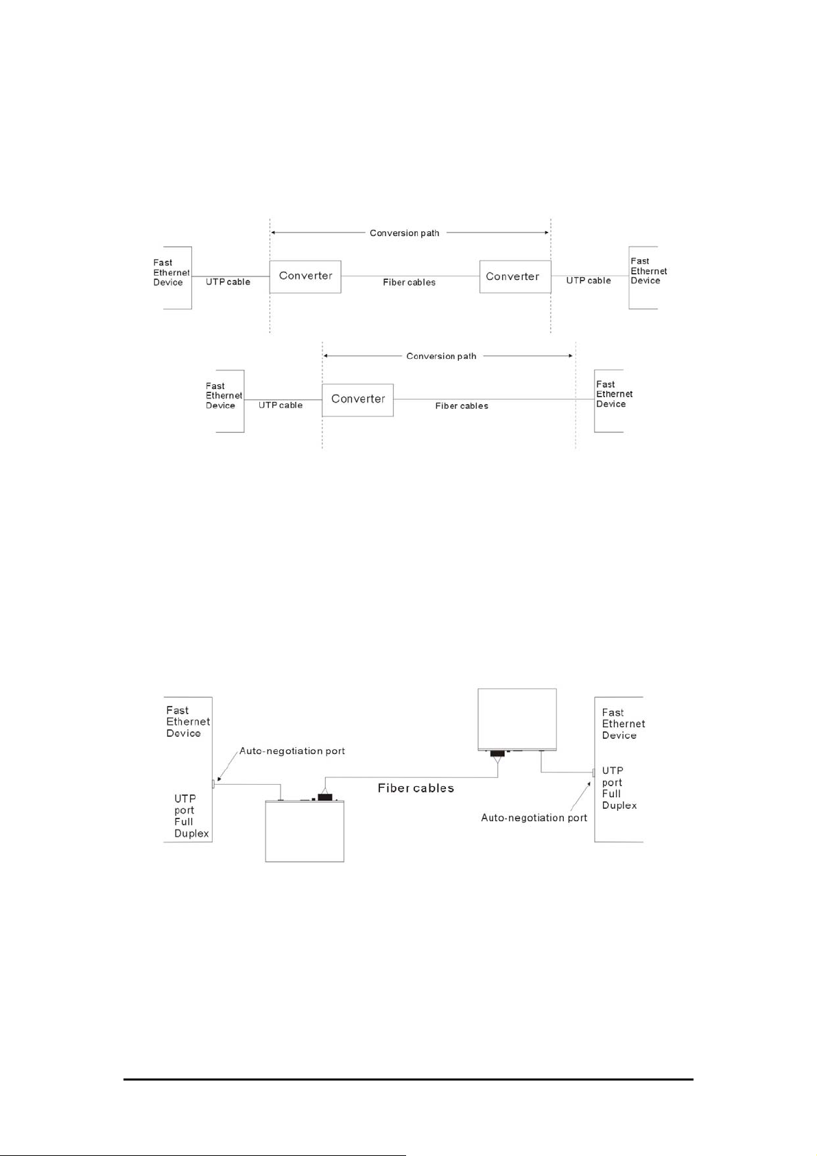
The converters serve as a conversion path between two Ethernet devices.
To both devices, the conversion is transparent. The connection could be
one of the following configurations :
Important rule : When a connection is established, make sure the
devices located at both ends of the path are configured and operated using
the same duplex mode and the maximum distance must comply with
IEEE 802.3u specifications.
The following figure illustrates a connection example between two
auto-negotiation devices. Both devices operate in full-duplex mode after a
negotiation process with the converters.
-7- Version 1.0, Oct/2004
Page 8

4 Interpreting LED Indicators
The LED labeled “UTP” is used to indicate the status of the TP port and
the LED labeled “FX” is for Fiber port.
LED Status State Interpretation
POWER Power status On
Off
UTP TP port link/Rx On
Off
Blink
FX Fiber port link/RX On
Off
Blink
Converter is on.
Converter is off.
The UTP link is ok.
No link or the link is faulty.
Receiving on TP port
The fiber link is ok.
No link or the link is faulty.
Receiving on Fiber port
The information contained in this document is subject to change without
prior notice.
-8- Version 1.0, Oct/2004
 Loading...