


MDC-211-WF
User Manual
Warranty
All products manufactured by ICP DAS are under warranty regarding
defective materials for a period of one year, beginning from the date of
delivery to the original purchaser.
Warning
ICP DAS assumes no liability for any damage resulting from the use of
this product. ICP DAS reserves the right to change this manual at any
time without notice. The information furnished by ICP DAS is believed to
be accurate and reliable. However, no responsibility is assumed by ICP
DAS for its use, or for any infringements of patents or other rights of
third parties resulting from its use.
Copyright
Copyright © 2020 by ICP DAS. All rights are reserved.
Trademarks
Names are used for identification purposes only and may be registered
trademarks of their respective companies.
Technical Support
If you have any problems, feel free to contact us via email at
service@icpdas.com.

ICP DAS, MDC-211-WF user manual , v1.1 Page 1
Copyright © 2020 by ICP DAS. All rights are reserved.
Table of Contents
1. Introduction ............................................ 3
1.1. Introduction to MDC-211-WF ................................................................................. 3
1.2. Product Features ....................................................................................................... 4
1.3. Specifications ............................................................................................................ 7
1.4. Size (Unit : mm) ........................................................................................................ 8
1.5. Configuration Instructions ...................................................................................... 9
2. Getting Started With MDC-211-WF ...................... 10
2.1. Preparation .............................................................................................................. 11
2.2. Login MDC-211-WF Web Interface ...................................................................... 14
2.3. Set Port Information .............................................................................................. 15
2.4. Set MDC-211-WF as Modbus Master ................................................................... 18
2.5. Set MDC-211-WF as Modbus Slave ...................................................................... 20
2.6. Check Modbus RTU Device Communication Status ........................................... 21
2.6.1. Check polling status of Modbus command ...................................................... 21
2.6.2. Inquire Corresponding Modbus Register Address .......................................... 23
2.6.3. Testing I/O Channel Status of Modbus RTU Device ........................................ 24
3. Export and Import the System Settings .................. 25
3.1. Export and Import the Configurations ................................................................ 25
3.2. Format Descriptions for the Configuration File (*.csv) ...................................... 27
4. Parameter Descriptions ................................. 34
4.1. Communication Interface Parameter Descriptions ............................................ 34
4.1.1. Wi-Fi Communication Interface ........................................................................... 34
4.1.2. Serial Port Communication Interface ................................................................. 35
4.2. Modbus Protocol Parameter Descriptions .......................................................... 36
4.2.1. Modbus Master Setting Parameters ................................................................... 36
4.2.2. Modbus Slave Setting Parameters ...................................................................... 37

ICP DAS, MDC-211-WF user manual , v1.1 Page 2
Copyright © 2020 by ICP DAS. All rights are reserved.
5. FAQ ................................................... 38
Q1 - What are the maximum numbers of polling definition and Internal Register in a
MDC-211-WF? .................................................................................................................... 38
Q2 - What is the maximum number of data can be accessed in one command from a
Modbus Master device? .................................................................................................... 38
Q3 - How are the Internal Registers corresponding to the polled data in a MDC-211WF? 38
Q4 - How to read each MDC-211-WF command status via the Modbus communication?
38
Q5 - How to update the firmware? .................................................................................. 40
6. Appendix .............................................. 43
6.1. LED Indicator State Descriptions .......................................................................... 43

ICP DAS, MDC-211-WF user manual , v1.1 Page 3
Copyright © 2020 by ICP DAS. All rights are reserved.
1. Introduction
This section describes the functions, features, software, and hardware specifications of the
MDC-211-WF Modbus data concentrator.
1.1. Introduction to MDC-211-WF
◆ Functions
MDC-211-WF Modbus data concentrator developed by ICP DAS, with Ethernet, Wi-Fi
Wireless, RS-232 and RS-485 communication interfaces, can link the Modbus RTU devices to
the Ethernet network. MDC-211-WF can read the data of Modbus RTU device according to
the user-defined command table, and integrate the data of different Modbus RTU devices
into the format of the continuous address so that the remote monitor host can connect to
MDC-211-WF from Ethernet to access the data of multiple Modbus RTU devices at once.
Through MDC-211-WF's Modbus data centralized management function, as well as the
Ethernet network convenient link and the communication ability, can quickly establish the
stable remote monitoring system, let the user be able to easily simplify the data acquisition
difficulty, and reduces the Ethernet network traffic load, enhances the system efficiency.
◆ Advantages
The advantages of MDC-211-WF Modbus data concentrator, not only to help users
manage the Modbus RTU devices near the RS-232 and RS-485, even in the distance tough
cabling environment, can through the Wi-Fi wireless communication advantages, easy to link
the Modbus RTU devices.
In particular, in the widely used Supervisory Control and Data Acquisition (SCADA), with
simple settings, MDC-211-WF Modbus data concentrator can link the distributed Modbus
RTU devices to the Ethernet network, which is the best solution for the user to establish the
remote monitoring control system quickly.
ICP DAS, MDC-211-WF user manual , v1.1 Page 4
Copyright © 2020 by ICP DAS. All rights are reserved.
1.2. Product Features
◆ Support Modbus RTU Master
The Wi-Fi, RS-485, or RS-232 on the MDC-211-WF can be set as Modbus Master. MDC-
211-WF can read the data of the Modbus RTU device according to the user-defined command
table, and integrate the data of different Modbus RTU devices into the format of the
continuous address for centralized management.
◆ Support Modbus TCP/RTU Slave
The Wi-Fi, RS-485, RS-232 or Ethernet on the MDC-211-WF can be set as Modbus Slave,
so the control host can access multiple Modbus RTU devices via MDC-211-WF at once.
By establishing the function of Modbus Master and Modbus Slave, the Modbus data
monitoring control system will be more efficient, stable and flexible to meet the diverse
application sites.
◆ Support Web-based UI Operations
MDC-211-WF provides a simple, friendly Web interface (UI), users can login the MDC-
211-WF Web page via a Web Browser to set up and real-time detect the MDC-211-WF for
the communication status and update frequency of each Modbus RTU command.
ICP DAS, MDC-211-WF user manual , v1.1 Page 5
Copyright © 2020 by ICP DAS. All rights are reserved.
◆ Support Parameter Setting via CSV File
CSV (Comma-Separated Values) is a text file format that can be edited in spreadsheet
software or plain text files and has the advantage of being easy to use, read and maintain.
MDC-211-WF parameter setting includes the Modbus TCP communication ID and port
number, the Serial port communication parameters and the Modbus RTU commands that
settings can also be edited in a *.csv file and import into the MDC-211-WF from the Web UI,
and then start to monitor the data of the remote Modbus RTU devices.
◆ Support Wi-Fi Communication Protocol
The MDC-211-WF support Wi-Fi standard (IEEE 802.11 a/b/g/n). User can access the data
of Modbus/RTU by Wi-Fi. User can reduce the wire because of wireless communication.
Otherwise, the MDC-211-WF also support 5 GHz. The 5 GHz can avoid the other interferences
from 2.4 GHz.
MDC-211-WF supports two Wi-Fi modes. One is Wi-Fi AP(Limit-AP). The other is AP Client
(Infrastructure) mode. The following figure has shown the application of each mode.
ICP DAS, MDC-211-WF user manual , v1.1 Page 6
Copyright © 2020 by ICP DAS. All rights are reserved.
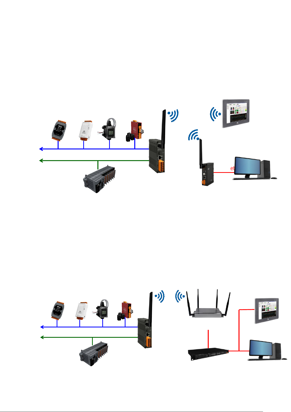
1. Limit-AP Mode
The MDC-211-WF is a Modbus/RTU to Modbus/TCP gateway in Limit-AP mode. The
device can connect to MDC-211-WF by Wi-Fi. The device can connect to the WF-2572M
when it didn’t have Wi-Fi function. The device can send Modbus/TCP command to acquire
data from Modbus/RTU device.
2. Infrastructure mode
The MDC-211-WF is a Wi-Fi AP client in the Wi-Fi infrastructure mode. The MDC-211-
WF can connect to other Wi-Fi AP. The SCADA/HMI and control center can connect
together by Ethernet switch. The device can send Modbus/TCP command to acquire data
from Modbus/RTU device.
RS-485
M-7000 tM
DL-100 PM-3000
PAC
RS-232
MDC-211-WF
(Limit APMode)
SCADA/HMI
Ethernet
WF-2572M
Control Center
Wi-Fi
2.4/5 GHz
RS-485
M-7000 tM
DL-100 PM-3000
PAC
RS-232
MDC-211-WF
(Infrastructure Mode)
APW77BAM
(Wi-Fi AP)
Switch
SCADA/HMI
Ethernet
Control Center
Wi-Fi
2.4/5 GHz

ICP DAS, MDC-211-WF user manual , v1.1 Page 7
Copyright © 2020 by ICP DAS. All rights are reserved.
1.3. Specifications
MDC-211-WF
Radio Standard
Standard
IEEE 802.11 a/b/g/n
Band
2.4 GHz: CH1~11; 5 GHz: CH36、40、44、48
Mode
Limit-AP/Infrasturcture
Encryption
Open/WEP/WPA/WPA2
Antenna
Omni-Directional; 3 dBi @ 2.4 GHz; 5.5 dBi @ 5 GHz
Transmit Range (LOS)
50 m (LOS)
Protocol
Modbus TCP slave
Ethernet Network
Port
x1, 10/100 Base-TX
Protocol
Modbus TCP Slave
Serial port (COM)
RS-232
x1, (TxD, RxD and GND)
RS-485
x1, (D+, D-)
Baud Rate
1200 ~ 115200 (bps)
Data Format
N81, N82, O71, O81, E71, E81, S71, S81, M71, M81
Protocol
Modbus RTU Master/Slave
Polling Definition
Up to 240 Modbus command definitions for all Wi-Fi/RS232/ RS-485 ports
Shared Memory
9600 registers for each of AI, AO, DI and DO data
Institutions
Casing
Metal
Dimensions (L x W x H)
120 mm x 33 mm x 116 mm
Installation
DIN-Rail
Power
Required Supply Voltage
+10 VDC ~ +30 VDC
Power Consumption
5 W @ 24 VDC
Environment
Operating Temperature
-25°C ~ +75°C
Storage Temperature
-30°C ~ +80°C
Humidity
10~90% RH, Non-condensing
ICP DAS, MDC-211-WF user manual , v1.1 Page 8
Copyright © 2020 by ICP DAS. All rights are reserved.
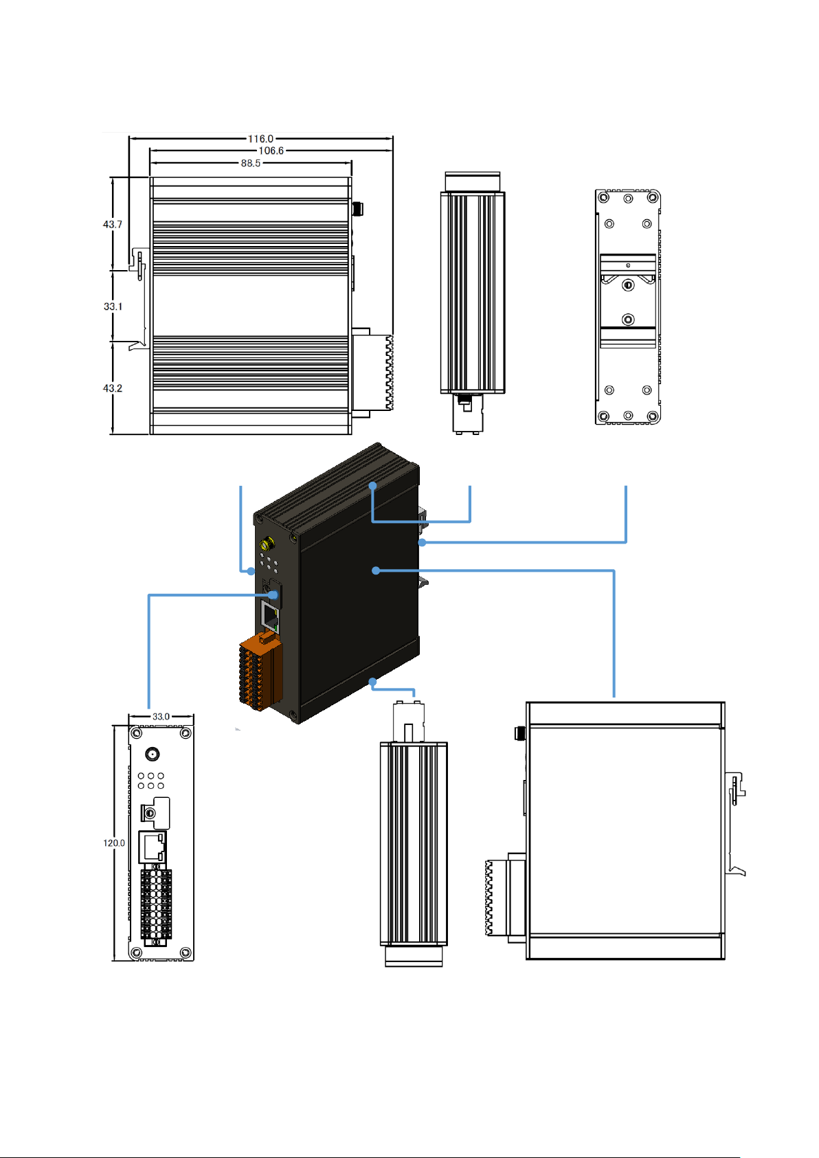
1.4. Size (Unit : mm)
Top view
Right view
Front view
Bottom view
Post view
Left view
ICP DAS, MDC-211-WF user manual , v1.1 Page 9
Copyright © 2020 by ICP DAS. All rights are reserved.
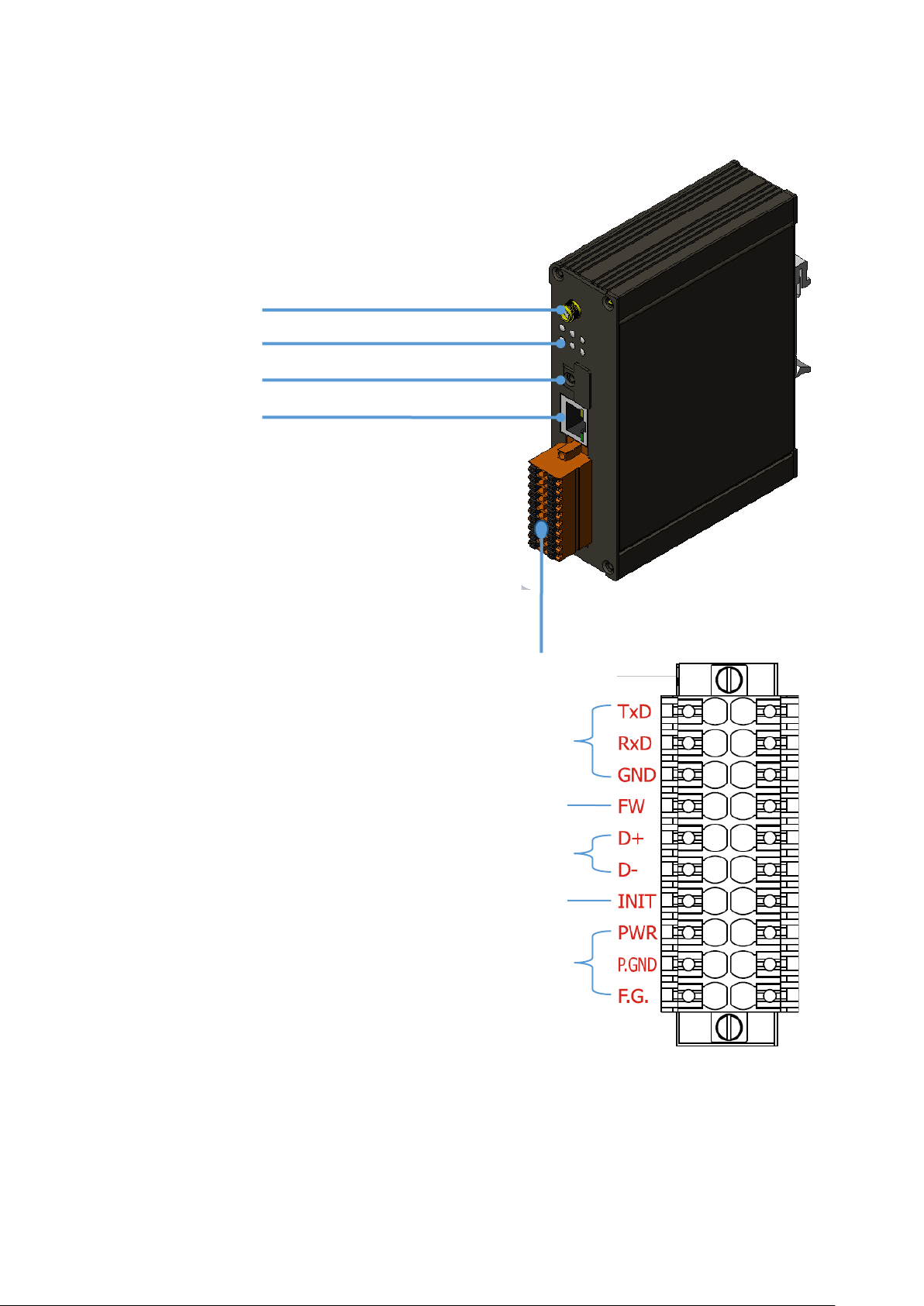
1.5. Configuration Instructions
Antenna
LED Indicator
MicroSD Card
Ethernet Port
Terminal Block
The MDC-211-WF is equipped with a RJ45 port for
Ethernet LAN connection. When 100BASE‐TX is
operating, the 10/100M LED is lit orange. When
10BASE‐T is operating or the machine is not connected
to the network, it is turned off. When an Ethernet link is
detected and an Ethernet packet is received, the Link/Act
LED is lit green.
RS-232
FW (Update)
RS-485
INIT
Power

ICP DAS, MDC-211-WF user manual , v1.1 Page 10
Copyright © 2020 by ICP DAS. All rights are reserved.
2. Getting Started With MDC-211-WF
This chapter mainly describes the operation process of the MDC-211-WF, such as, how
to use the MDC-211-WF Web interface via browser, and set up the Modbus Master and
Modbus Slave function for the Modbus data concentrator.
◆ MDC-211-WF Setting Flowchart
Preparation
•Hardware wiring
•Set the MDC-211-WF and PC to the same local area network. (The default IP address of
MDC-211-WF is 192.168.255.1)
Web Login
•Launch the browser and enter the IP address of MDC-211-WF
•login MDC-211-WF (Both the default account and password are "Admin")
•Change a new account/password for higher security
Port
Settings
•Configure communication port settings according to the user needs.
Modbus
Master
•Set the communication interface to Modbus Master according to the actual requirements,
and adjust the related setting parameter values.
•Add Modbus RTU commands to specific communication port for Modbus data
acquisition.
Modbus
Slave
•Set the communication interface to Modbus Slave according to the actual requirements,
and set its Modbus Slave ID.
System
Backup
•Export: Export the MDC-211-WF setting parameters to a. csv file for backup.
•Import: Import the configurations into the MDC-211-WF via a .csv file.
Check
Polling State
•Check the polling state of each Modbus commands.
•Get the address mapping table between the remote Modbus RTU devices and Internal
Registers of MDC-211-WF.

ICP DAS, MDC-211-WF user manual , v1.1 Page 11
Copyright © 2020 by ICP DAS. All rights are reserved.
2.1. Preparation
Before setting up the MDC-211-WF, please complete the necessary preparation,
including hardware wiring, IP address settings, and so on, this section describes each.
◆ Hardware Wiring
Please follow Figure 2.1 wiring diagram, to wire the following items:
1. Power Supply : +10 VDC ~ +30 VDC
2. RS-485:D+ & D-
3. RS-232:TxD / RxD / GND
4. Ethernet:Connect the MDC-211-WF and computer into the same LAN through cable or
Ethernet Switch/Hub.
Figure 2.1 MDC-211-WF Wiring Diagram
RS-485
F.G.
P.GND
PWR
INIT
D-
D+
GND
RxD
TxD
RS-232
Power
Supply
Link/Act
10/100M
FW

ICP DAS, MDC-211-WF user manual , v1.1 Page 12
Copyright © 2020 by ICP DAS. All rights are reserved.
◆ Modifying IP address
Before connecting the MDC-211-WF, please set the MDC-211-WF to be the same LAN
as the PC. Tables 2.1 shows the default network setting of MDC-211-WF. If it is in the different
network area, please adjust network settings by the following software.
(1) eSearch Utility
http://ftp.icpdas.com/pub/cd/tinymodules/napdos/software/esearch/windows/
Table 2.1 Factory default network settings of MDC-211-WF
IP
192.168.255.1
Mask
255.255.0.0
Gateway
192.168.0.1
The following steps show how to modify the MDC-211-WF network settings through
eSearch Utility:
Steps 1 Click “Search Server” button to search for MDC-211-WF module
Steps 2 Select “MDC-211-WF”, and click “Configuration (UDP)” button, as shown in Figure 2.2
Fiagram 2.2 eSearch Utility operator interfaces
Step 3 Configure the network parameters in the pop-up settings window, and click "OK"
button to modify the network settings, as shown in Figure 2.3.

ICP DAS, MDC-211-WF user manual , v1.1 Page 13
Copyright © 2020 by ICP DAS. All rights are reserved.
Figure. 2.3 Network parameter setting interface
Step 4 Finally, click "Search Server" button again to find the MDC-211-WF module, to confirm
that the network settings has been modified successfully.

ICP DAS, MDC-211-WF user manual , v1.1 Page 14
Copyright © 2020 by ICP DAS. All rights are reserved.
2.2. Login MDC-211-WF Web Interface
This section describes how to login the MDC-211-WF Web interface.
Step1 Once the PC and MDC-211-WF are in the same LAN, user can login the MDC-211-WF
by entering the IP address on Web browser (IE11/Chrome/Firefox, resolution 800 x 600
or more is recommended), the login screen is shown as Figure 2.4:
Figure 2.4 Product Login Page
Step2 Enter the account and password for the MDC-211-WF Web page (case-insensitive)
and click the "Login" button.
- Default Account : Admin
- Default Password : Admin
Step3 Click "System Information" → "Account Management" to modify account and
password for higher security, as shown in Figure 2.5
Figure 2.5 Account Management

ICP DAS, MDC-211-WF user manual , v1.1 Page 15
Copyright © 2020 by ICP DAS. All rights are reserved.
2.3. Set Port Information
MDC-211-WF provides one port Wi-Fi, one port Ethernet, one port RS-232 and one port
RS-485 communication interface, this section introduces the configuration procedure for
these communication interface.
◆ Wi-Fi Port Setting
Click "Module Setting" → "Wi-Fi", to read the current Wi-Fi setting parameters, if user
want to adjust the Wi-Fi settings, click the "Modify" button to switch to the configuration
page, as shown in Figure 2.6.
Figure 2.6 Steps to switch to the Wi-Fi configuration page
For the description of the Wi-Fi settings, please refer to section “4.1.1 Wi-Fi
Communication Interface”. After modifying the setting parameters, please remember to click
"Save" button to save the changes, or click the "Cancel" button to discard the configuration
and return to the previous page.
NOTE - The new Wi-Fi settings will take effect immediately after configuration without
1
2
3
4

ICP DAS, MDC-211-WF user manual , v1.1 Page 16
Copyright © 2020 by ICP DAS. All rights are reserved.
restarting the power of the MDC-211-WF.
◆ Ethernet Port Setting
Click "Module Setting" → "Ethernet", to read the current Ethernet setting parameters, if
user want to adjust the Ethernet settings, click the "Modify" button to switch to the
configuration page, as shown in Figure 2.7.
Figure 2.7 Steps to switch to the Ethernet configuration page
After modifying the setting parameters, please remember to click "Save" button to save
the changes, or click the "Cancel" button to discard the configuration and return to the
previous page.
NOTE - The new Ethernet settings only take effect after restarting the power of the MDC-
211-WF.
3
4
1
2

ICP DAS, MDC-211-WF user manual , v1.1 Page 17
Copyright © 2020 by ICP DAS. All rights are reserved.
◆ Serial Port Setting
Click "Module Setting" → "Serial Port", to read the current RS-232 and RS-485 setting
parameters, if user want to adjust the configurations of Serial Port, click the "Modify" button
to switch to the configuration page, as shown in Figure 2.8.
Figure 2.8 Steps to switch to the Serial Port configuration page
For the description of the Serial Port settings, please refer to section “4.1.2 Serial Port
Communication Interface". After modifying the setting parameters, please remember to click
"Save" button to save the changes, or click the "Cancel" button to discard the configuration
and return to the previous page.
NOTE - The new Serial Port settings will take effect immediately after configuration without
restarting the power of the MDC-211-WF.
2
3
4
1

ICP DAS, MDC-211-WF user manual , v1.1 Page 18
Copyright © 2020 by ICP DAS. All rights are reserved.
2.4. Set MDC-211-WF as Modbus Master
Each Wi-Fi/RS-232/RS-485 communication interface on MDC-211-WF can be either set
as Modbus Master or Modbus Slave. This section describes how to set the communication
interface as the Modbus Master, and add the Modbus RTU devices to be monitored.
◆ Read current Modbus protocol setting values
Click "Module Setting" → "Modbus RTU/TCP", to read the current setting parameters of
the Modbus RTU/TCP protocol for each communication interface, if user want to modify these
configurations, click the "Modify" button to switch to the configuration page, as shown in
Figure 2.9.
Figure 2.9 Steps to switch to the Modbus protocol configuration page
2
1
3
4

ICP DAS, MDC-211-WF user manual , v1.1 Page 19
Copyright © 2020 by ICP DAS. All rights are reserved.
◆ Set the specified communication interface as Modbus Master
Click the "Module Setting" → "Modbus RTU/TCP" → "Wi-Fi/RS-232/RS-485", to select
the to “Modbus Master” in the "Modbus Mode" configuration field. For the description of the
Modbus Communication Interface settings, please refer to section “4.2 Modbus Protocol
Parameter Descriptions".
◆ Add the Modbus RTU devices that want to control
Step1 After setting the protocol to Modbus Master (refer to Figure 2.9), click the icon " "
at the bottom of "Modbus Device" to add a Modbus RTU Slave device and give the
module name (up to 12 ASCII characters) and Modbus address (the Slave station
number (1~255) of the Modbus RTU).
Step2 Following the Figure 2.10, click the icon " " at the bottom of Modbus RTU Slave
module to add a Modbus RTU Register, and set the Modbus Function Code, Start
address, Length and Range of the Register.
Figure 2.10 Add Modbus RTU Slave Module/Register window
Step3 After settings, click "OK" for saving the changes. If you want to discard the changes
please click "Cancel" go back to the previous page. If you want to remove the Modbus
register, click the icon " ".

ICP DAS, MDC-211-WF user manual , v1.1 Page 20
Copyright © 2020 by ICP DAS. All rights are reserved.
2.5. Set MDC-211-WF as Modbus Slave
One of the MDC-211-WF Wi-Fi/RS-232/RS-485 ports can be set as Modbus Master or
Modbus Slave (Ethernet port can only be used as Modbus Slave). This section describes how
to set the communication interface as Modbus Slave.
◆ Set communication interface to Modbus Slave
Click "Module Setting" → "Modbus RTU/TCP" → click "Modify" → Select the one of
the " Wi-Fi / RS-232 / RS-485" and set "Modbus Status" as Modbus Slave. Finally, set the
station number (1~255) of MDC-211-WF as the Modbus Slave.
Figure 2.11 Modbus RTU/TCP Protocol parameter setting page
◆ Modbus Internal Register Address of MDC-211-WF
When MDC-211-WF as Modbus Slave, the external controller can indirectly read the data
of the Modbus RTU devices, for its corresponding Modbus Register information, refer to "2.6.2
Inquire Modbus Inner- register address of the corresponding relationship".
2
1
3
4

ICP DAS, MDC-211-WF user manual , v1.1 Page 21
Copyright © 2020 by ICP DAS. All rights are reserved.
2.6. Check Modbus RTU Device Communication Status
The user can view and monitor the status of each Modbus command directly on the
MDC-211-WF Web interface. This section describes how to check the Modbus command
status, real-time monitor the I/O channel status of Modbus RTU device, and inquire the
relationship for the Modbus RTU device I/O and the MDC-211-WF Internal Register address.
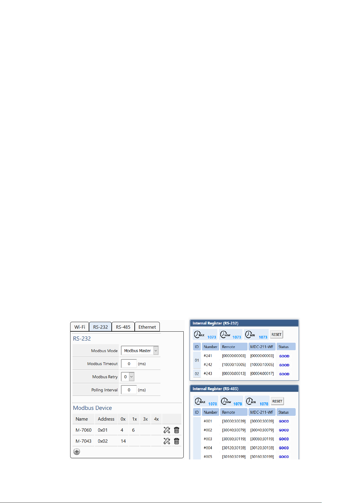
2.6.1. Check polling status of Modbus command
Click "I/O Information" → "Internal Register", the browser will load the Modbus
command real-time information as Figure 2.12, the descriptions please see Table 2.2.
Figure 2.12 Modbus Command Communication real-time Status page
Table 2.2 I/O information real-time display description
Item
Description
ID
Modbus RTU Slave Module Station number
Number
MDC-211-WF Modbus Command Polling order and corresponding
Internal Register order
Remote
Modbus RTU Slave Module Register address
MDC-211-WF
MDC-211-WF Internal Register address
Status
Modbus Command Polling status
If want to inquire the Modbus command communication status between MDC-211-WF

ICP DAS, MDC-211-WF user manual , v1.1 Page 22
Copyright © 2020 by ICP DAS. All rights are reserved.
and Modbus RTU devices, please refer to the “Status" item:
(1) If the "Status" item displays GOOD, means the command is connected and reading data
currently.
(2) If the "Status" item displays DISABLED, means the command was disabled by the user.
(3) If the "Status" item displays TIMEOUT, means the command was timeout and the device
did not respond, please check the module wiring, and the following Modbus RTU device
settings those need to be consistent with the settings in MDC-211-WF.
- Baud Rate
- Data Format (Data Bit / Parity / Stop Bit)
- Station number (ID) of the Modbus RTU Slave device
(4) If the "Status" item displays ILLEGAL DATA FUNCTION, represents Modbus Exception
code 01, which means the command connection was established, but the Modbus RTU
device of the communication target does not support the function code, please recheck
the Modbus command parameters.
(5) If the "Status" item displays ILLEGAL DATA ADDRESS, represents Modbus Exception
Code 02, which means the command connection was established, but the Modbus RTU
device of the communication target does not support the Starting Register address, or
exceeds the legal Register range (Starting + Length) , please recheck the Modbus
command parameters.
(6) If the "Status" item displays ILLEGAL DATA VALUE, represents Modbus Exception Code
03, means the command connection was established, but the Quantity of the command
access Register is not valid, please recheck the Modbus command parameters.
(7) If the "Status" item displays CRC ERROR, means the Modbus CRC code error and the
communication may be disturbed abnormally.

ICP DAS, MDC-211-WF user manual , v1.1 Page 23
Copyright © 2020 by ICP DAS. All rights are reserved.
2.6.2. Inquire Corresponding Modbus Register Address
When the users define a Modbus command, MDC-211-WF automatically generates the
corresponding Internal Register address according to the order of the Modbus command.
The users only need to select "I/O Information" → "Internal Register", the browser will
automatically load the Modbus Register mapping table.
Table 2.3 Modbus Command Definition Example
#
ModbusDevice
# PortNo.
ModbusSlaveID
ModuleName
FunctionCode
RegStartAddr
RegCount * 0 1 M-7060 1 0
4 * 0 1 M-7060 2 0
6 * 0 2 M-7060 1 0
4 * 0 2 M-7060 2 0
6 #
For example of the table 2.3 above, the browser will load the Modbus Register mapping
table as Figure 2.13. The "Remote" item in the mapping table represents the Register address
of the Modbus RTU device; the "MDC-211-WF" item represents the corresponding Internal
Register address. The users can access Internal Register address in the “MDC-211-WF" item
via the Modbus protocol to control the entity Modbus RTU device.
Figure 2.13 Modbus Register Mapping Table in Web Interface

ICP DAS, MDC-211-WF user manual , v1.1 Page 24
Copyright © 2020 by ICP DAS. All rights are reserved.
2.6.3. Testing I/O Channel Status of Modbus RTU Device
MDC-211-WF can real-time control the I/O channel of Modbus RTU devices via the
standard Modbus protocol, and also provide Web UI to real-time control the Modbus I/O
channel status. As Figure 2.14, users only need to click "I/O Information" and select the
Modbus RTU device want to control, the Web UI will display the pre-set Modbus command
and real-time display that Modbus device I/O channel status. The user can directly click I/O
channel to change the I/O channel status.
Figure 2.14 Modbus I/O information real-time displa page
2
1
3
2
1
3
4
ICP DAS, MDC-211-WF user manual , v1.1 Page 25
Copyright © 2020 by ICP DAS. All rights are reserved.
3. Export and Import the System Settings
The user can set up MDC-211-WF via the Web UI, and also can export the configuration
to a *.csv file in the local computer for backup. More, the user can directly edit the setting
parameters in a *.csv file and import the *.csv file into the MDC-211-WF module to complete
the module setting.
This chapter introduces how to export and import the *.csv file, and describes the format
and setting code for the *.csv file, and some setting recommendations.
NOTE - *.csv file is a text file format that can be edited in spreadsheet software or plain text
files and has the advantage of being easy to use, read and maintain. It uses commas "," to
separate each column in a plain-text editor.
3.1. Export and Import the Configurations
This section describes the process to import and export the module configuration.
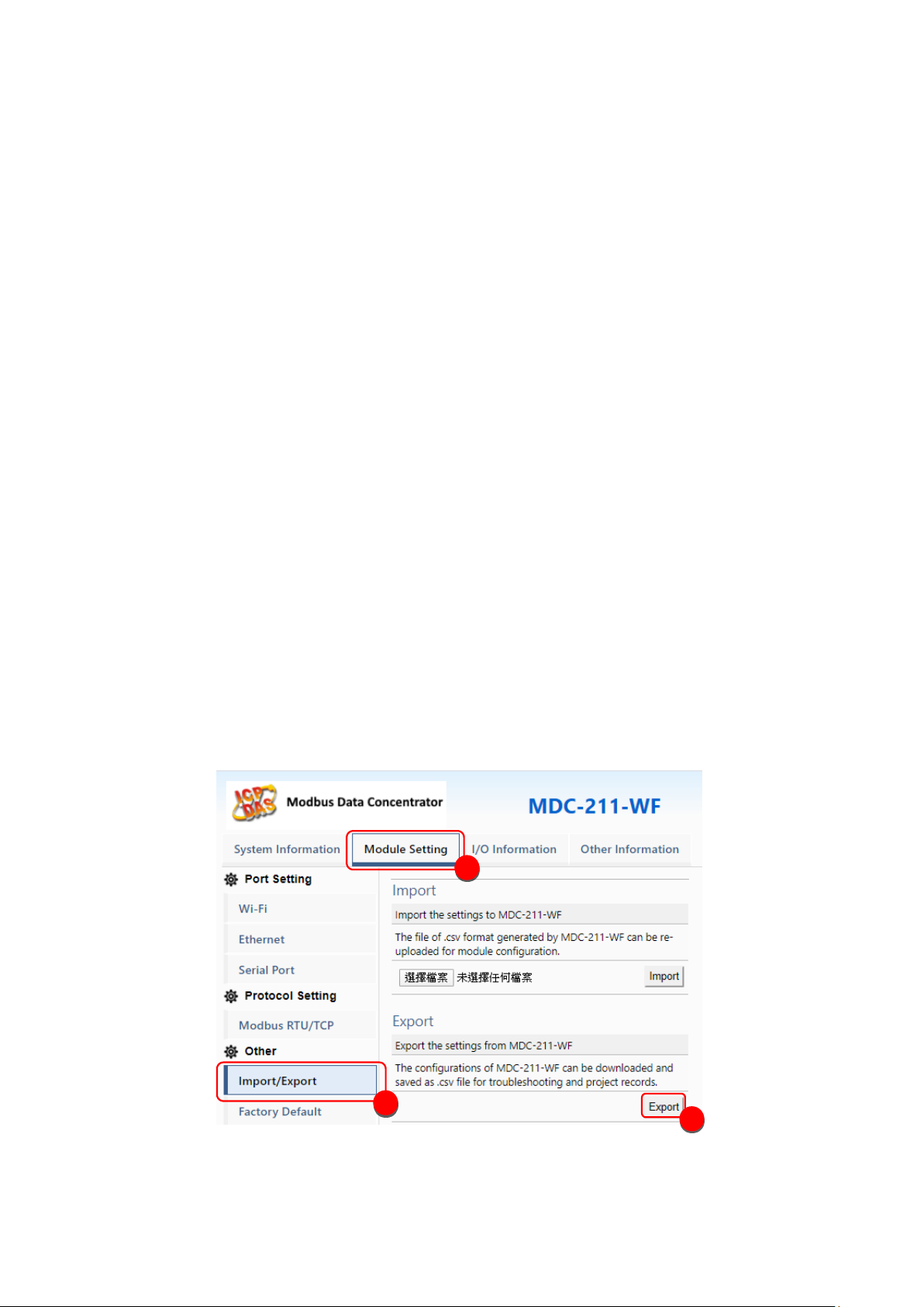
◆ Export
As Figure 3.1, select "Module Setting" → "Import/Export" → "Export" to export the
configurations of MDC-211-WF to a *.csv file.
Figure 3.1 Module Setting Export page
1
2
3

ICP DAS, MDC-211-WF user manual , v1.1 Page 26
Copyright © 2020 by ICP DAS. All rights are reserved.
◆ Import
As Figure 3.2, click "Module Setting" → "Import/Export" → "Choose file" → "Import",
then the *.csv file can be uploaded into MDC-211-WF and set up immediately.
Figure 3.2 Module Setting Import page
2
1
3
4

ICP DAS, MDC-211-WF user manual , v1.1 Page 27
Copyright © 2020 by ICP DAS. All rights are reserved.
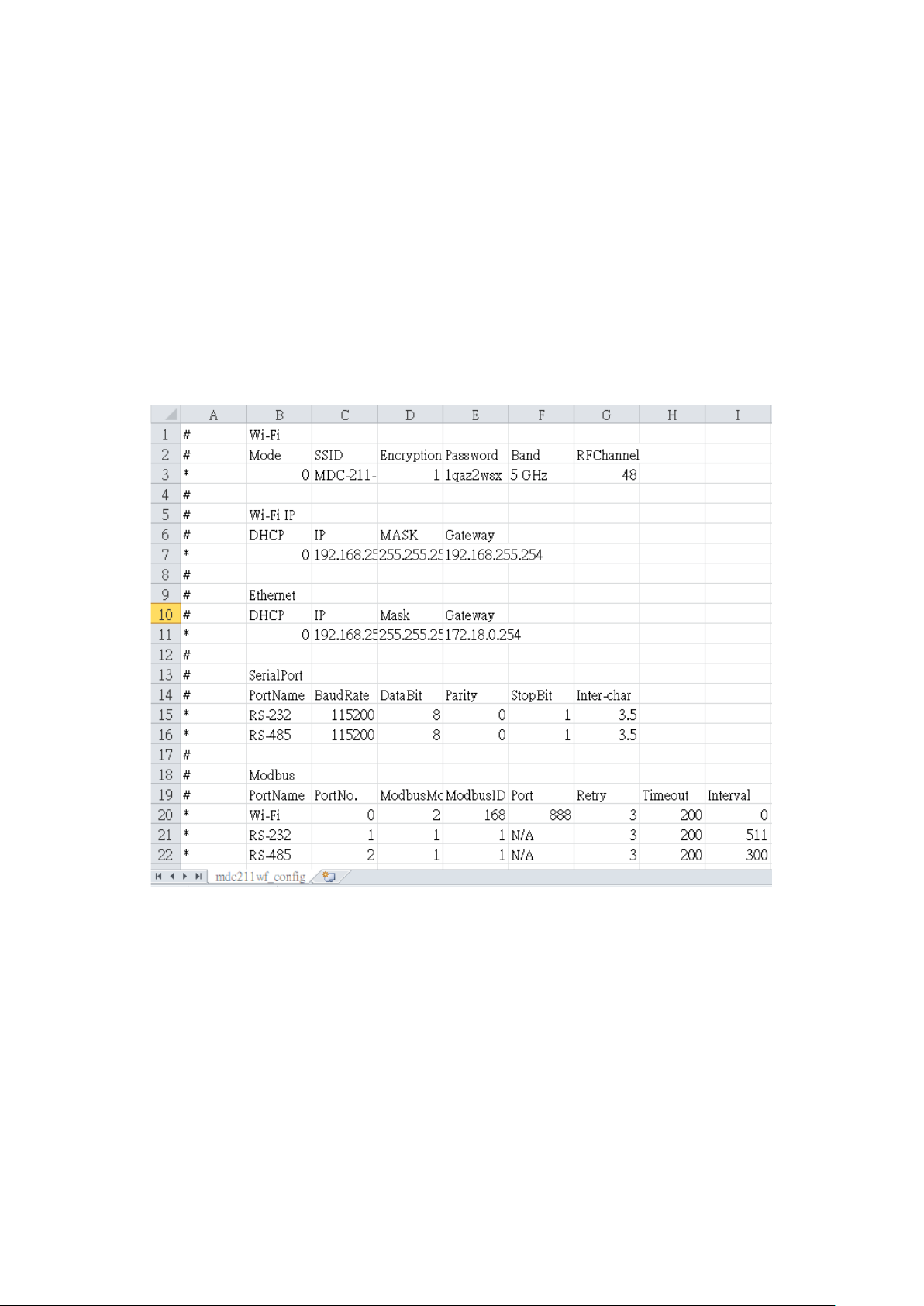
3.2. Format Descriptions for the Configuration File (*.csv)
If the user wants to set up MDC-211-WF through the *.csv configuration file, the user can
export a *.csv file from the Web Interface as the configuration template. For the detail steps,
please refer to "3.1 Export and Import the Configurations ".
The MDC-211-WF configuration file includes all setting parameters. The label name and
order must be the same as the example in Figure 3.3. Below will introduce the settings of Wi-
Fi, Serial port and Ethernet, and the settings for Modbus Master and Modbus Slave.
NOTE - *.csv template can be got via the MDC-211-WF Web Interface (refer to Section 3.1).
Figure 3.3 MDC-211-WF configuration file (*.csv)

ICP DAS, MDC-211-WF user manual , v1.1 Page 28
Copyright © 2020 by ICP DAS. All rights are reserved.
◆ Wi-Fi Communication Settings
The first part is for Wi-Fi and IP settings. Wi-Fi parameter descriptions may refer to "4.1.1
Wi-Fi Communication Interface", the label name and setting descriptions see Table 3.1 and
Table 3.2 below.
#
Wi-Fi
#
Mode
SSID
Encryption
Password
Band
RF Channel
* 0 MDC-211-WF
1
1qaz2wsx 1 48
#
Table 3.1 Wi-Fi settings and descriptions
Item
Label Name
Valid Code & Range
Mode
Mode
0: Limit-AP
1: Infrastructure
Default value: Limit-AP
SSID
SSID
The maximum length of SSID is 32 words
Default value: MDC-211-WF
Encryption
Encryption
Limit-AP mode
1: OPEN
2: WPA2
3: WPA/WPA2
4: WPA
5: WEP
Infrastructure mode
1: OPEN
2: WPA/WPA2
5: WEP
Password
Password
The maximum length of password is 63 words

ICP DAS, MDC-211-WF user manual , v1.1 Page 29
Copyright © 2020 by ICP DAS. All rights are reserved.
Default value: 1qaz2wsx
RF Band
RF Band
0: 2.4 GHz
1: 5 GHz
RF Channel
RF Channel
2.4 GHz: CH1~11
5 GHz: 36、40、44、48
#
Wi-Fi IP
#
DHCP
IP
Mask
Gateway * 0
192.168.255.2
255.255.255.0
192.168.255.254
#
Table 3.2 Wi-Fi IP settings and descriptions
Item
Label Name
Valid Code & Range
DHCP
DHCP
DHCP of Wi-Fi
0: disable
1: Enable
Default value: ”0”
IP
IP
IP of Wi-Fi
Default value: 192.168.255.2
Mask
Mask
Mask of Wi-Fi
Default value: 255.255.255.0
Gateway
Gateway
Gateway of Wi-Fi
Default value: 192.168.255.254
◆ Ethernet Communication Settings
The second part is for Ethernet settings. Ethernet label name and setting descriptions
please see table 3.3 below.

ICP DAS, MDC-211-WF user manual , v1.1 Page 30
Copyright © 2020 by ICP DAS. All rights are reserved.
#
Ethernet
# DHCP
IP
Mask
Gateway * 0
192.168.255.1
255.255.0.0
192.168.0.1 #
Table 3.3 Ethernet settings and descriptions
Item
Label Name
Valid Code & Range
DHCP
DHCP
0 (Disable) / 1 (Enable)
NOTE – The IP, Mask and Gateway should be set up according to the local network.

ICP DAS, MDC-211-WF user manual , v1.1 Page 31
Copyright © 2020 by ICP DAS. All rights are reserved.
◆ Serial Port Communication Settings
The third part is for Serial port settings. Serial port parameter descriptions may refer to
"4.1.2 Serial Port Communication Interface", the label name and setting descriptions please
see table 3.4 below.
#
SerialPort
# PortName
BaudRate
DataBit
Parity
StopBit
CharTime
*
RS-232
115200
8 0 1
3.5
*
RS-485
115200
8 0 1
3.5 #
Table 3.4 Serial port settings and descriptions
Item
Label Name
Note
Port Name
PortName
The name of the Serial port; the location and content
are unmodifiable.
Baud Rate
BaudRate
115200 / 57600 / 38400 / 19200 / 9600 / 4800 / 2400
/ 1200 (Unit: bps)
Data Format
DataBit
7 / 8
Parity
0 (None) / 1 (Odd) / 2 (Even) / 3 (Mark) / 4 (Space)
StopBit
0 / 1 / 2
Inter-character
Timeout
CharTime
1.5 ~ 10 (Unit: Character Time)

ICP DAS, MDC-211-WF user manual , v1.1 Page 32
Copyright © 2020 by ICP DAS. All rights are reserved.
◆ Modbus Mode Settings
The fourth part is for Modbus mode settings. Modbus parameter descriptions may refer
to Section 4.2, the label name and setting descriptions please see Table 3.5 below.
#
Modbus
#
PortName
PortNo.
ModbusMode
ModbusID
Retry
Timeout
Interval
*
Wi-Fi
0 1 1
3
200
30
*
RS-232
1 0 1
3
150
0
*
RS-485
2 1 1
3
150
20
*
Ethernet
N/A
N/A
1
#
Table 3.5 Modbus protocol settings and descriptions
Item
Label Name
Note
Port Name
PortName
The name of the Modbus communication port;
the location and content are unmodifiable.
Port Number
PortNo.
The number of the Modbus communication port;
the location and content are unmodifiable.
Modbus Mode
ModbusMode
0 (Disable) / 1 (Modbus Master) / 2 (Modbus
Slave)
Ethernet fixed to Modbus Slave, no need to set
Modbus Retry
Retry
0 ~ 9
Modbus Timeout
Timeout
0 ~ 65535
Polling Interval
Interval
0 ~ 65535

ICP DAS, MDC-211-WF user manual , v1.1 Page 33
Copyright © 2020 by ICP DAS. All rights are reserved.
◆ Modbus Command Settings
The fifth part is for Modbus command settings. The label name and setting descriptions
please see Table 3.6 below.
#
ModbusCommand
# PortNo.
ModbusSlaveID
ModuleName
FunctionCode
RegStartAddr
RegCount
*
2 1 M-7017 4 0
8
*
2 2 M-7024 3 0
4 #
Table 3.6 Modbus RTU device settings and descriptions
Item
Label Name
Note
Port Number
PortNo.
1 (RS-232) / 2 (RS-485)
Modbus Slave ID
ModbusSlaveID
1 ~ 255
Module Name
ModuleName
Up to 12 ASCII characters
Function Code
FunctionCode
1 (Read/Write DO) / 2 (Read DI) / 3 (Read/Write AO)
/ 4 (Read AI)
Starting Address
RegStartAddr
0 ~ 65535
Quantity of
Register
RegCount
1 ~ 64
[Note] The first column of the *.csv file has different meanings. It marks as:
"#": means the system-defined label; do not change the name and location (order).
"*": means the data that the user enabled.
"-": means the data that the user does not enable.

ICP DAS, MDC-211-WF user manual , v1.1 Page 34
Copyright © 2020 by ICP DAS. All rights are reserved.
4. Parameter Descriptions
This chapter introduces a variety of setting parameters and examples for the users to
follow and set up the modules.
4.1. Communication Interface Parameter Descriptions
4.1.1. Wi-Fi Communication Interface
◆ Parameter descriptions
Table 4.1 shows the descriptions for the Wi-Fi parameters, setting range and notes.
Table 4.1 Wi-Fi related parameter descriptions
Item
Description
Mode
Note
Mode
Wi-Fi
Operation mode
Limit-AP
Wi-Fi AP mode: It can connect by AP client.
Infrastructure
Wi-Fi AP Client mode: It can connect to Wi-Fi AP.
SSID
Wi-Fi SSID
Limit-AP
SSID of Wi-Fi AP
Infrastructure
The AP client will connect to AP with same SSID.
Encryption
Encryption
Limit-AP
Encryption of Wi-Fi AP
Infrastructure
The AP client will connect to AP with same
encryption.
Password
Password
Limit-AP
Password of Wi-Fi AP
Infrastructure
The AP client will connect to AP with same
password.
Band
Wireless Band
Limit-AP
The band of Wi-Fi AP (2.4 or 5 GHz)
RFChannel
Wireless Channel
Limit-AP
The channel of Wi-Fi AP
The application of Wi-Fi AP and Infrastructure mode can refer to page 6.

ICP DAS, MDC-211-WF user manual , v1.1 Page 35
Copyright © 2020 by ICP DAS. All rights are reserved.
4.1.2. Serial Port Communication Interface
◆ Parameter description
Table 4.3 below is the descriptions for the Serial port parameters and setting notes.
Table 4.3 Serial port related parameter descriptions
Project
Description
Note
Baud Rate
Communication
Baud rate
Support eight kinds of communication baud rate 115200 / 57600 / 38400 / 19200 / 9600 / 4800 / 2400 /
1200 bps
Please set the same as the Modbus RTU device
Data Format
Communication
Data format
Support five kinds of parity check codes - None / Odd
/ Even / Mark / Space
Supports 7/8 data bit
Support 0/1/2 stop bit
Set the same with the connected Modbus RTU device
Inter-character
Timeout
Timeout for
ending
command
reception
Valid range is 1.5 to 10 character-time
The default is the standard Modbus communication
protocol 3.5 character time, the user can adjust
according to the requirement
◆ Set Example
Table 4.4 shows a setting example to set the RS-485 of MDC-211-WF as a Modbus
Master, and the recommend parameter values for the Serial port.
Table 4.4 MDC-211-WF and M-7000/PLC setting example
Project
MDC-211-WF
M-7017
M-7060
PLC
Baud Rate
115200
Data Format
N,8,1
Inter-character Timeout
3.5
N/A
N/A
N/A

ICP DAS, MDC-211-WF user manual , v1.1 Page 36
Copyright © 2020 by ICP DAS. All rights are reserved.
4.2. Modbus Protocol Parameter Descriptions
MDC-211-WF is a Modbus data concentrator with Wi-Fi / RS-232 / RS-485 / Ethernet
interfaces. The users need to set a communication interface to Modbus Master / Modbus
Slave (The interface not used can be set to “Disabled”). The following sections describe the
parameters for setting to Modbus Master and Modbus Slave.
4.2.1. Modbus Master Setting Parameters
◆ Parameter Description
Table 4.5 shows the descriptions for the Modbus Master setting parameters and the
setting notes.
Table 4.5 Modbus Master related parameter descriptions
Item
Description
Note
Modbus
Timeout
Polling
Timeout
It is the maximum time for waiting the response from Modbus
RTU device. If there is no response after the time expires, it is
considered as timeout and execute the next command.
Users can change the value as needed.
Modbus
Retry
Number of
polling
Retries
When the number of command timeouts exceeds the number
of retries, the MDC-211-WF regards the Modbus RTU device as
offline and performs the following two operations:
a. Suspend this polling command for 10 seconds until the device
is back online again
b. The status of the Modbus command can be read via the
Internal Register of MDC-211-WF, where the Register value of
0xFFFF is represented the timeout. (For more information can
see Chapter 5. FAQ-Q5)
The default of Modbus Retry is 3 times, users can change the
value as needed
Polling
Interval
Polling
Interval
The interval time for command polling to avoid
communication signal collisions.
Users can change the value as needed

ICP DAS, MDC-211-WF user manual , v1.1 Page 37
Copyright © 2020 by ICP DAS. All rights are reserved.
◆ Example
Table 4.6 below is a setting example to set MDC-211-WF to Modbus Master, and the
recommend parameters.
Table 4.6 MDC-211-WF and M-7000 or PLC communication setting example
Project
Wi-Fi
RS-485
RS-232
Modbus Timeout
200
150
150
Modbus Retry
3 3 3
Polling Interval
30
20
0
4.2.2. Modbus Slave Setting Parameters
◆ Parameter description
Table 4.7 below is the descriptions for Modbus Slave setting parameters and the setting
notes.
Table 4.7 Modbus Master related parameter descriptions
Item
Description
Note
Modbus ID
Modbus
Station
Number
The station number for setting MDC-211-WF to Modbus
Slave
Users can change the value as needed (1~255)

ICP DAS, MDC-211-WF user manual , v1.1 Page 38
Copyright © 2020 by ICP DAS. All rights are reserved.
5. FAQ
Q1 - What are the maximum numbers of polling definition and Internal
Register in a MDC-211-WF?
The maximum number of polling definition in a MDC-211-WF is 240 commands, each
definition can access up to 64 Internal Registers. Each of the four tables (DI/DO/AI/DO) can
store up to 9600 Internal Registers for polled data.
Q2 - What is the maximum number of data can be accessed in one
command from a Modbus Master device?
By the Modbus TCP protocol, the maximum amount of Internal Registers that one Modbus
command can access is 255 of function code 01 and 02, and 126 of function code 03 and 04.
Q3 - How are the Internal Registers corresponding to the polled data in a
MDC-211-WF?
Please refer to the "2.6.2 Inquire Corresponding Modbus Register Address" for the detail
information.
Q4 - How to read each MDC-211-WF command status via the Modbus
communication?
MDC-211-WF can view the real-time status of each Modbus command directly in a
Web UI, and also store the status in the Internal Register starting with the address 39600
(0x2580), that meaning the Modbus Master can use function code 04 to read the command
status. One command can read up to 126 Internal Register data.

ICP DAS, MDC-211-WF user manual , v1.1 Page 39
Copyright © 2020 by ICP DAS. All rights are reserved.
Figure 5.2 Modbus command real-time status example
For example of Figure 5.2 above, Modbus Master uses the function code 04 to read the
connection status from 39600 as Table 5.1.
Table 5.1 The corresponding Internal Register address of the command status
Command No.
Addresses
State Code
Web Page Display
#001
39600
00 00
GOOD
#002
39601
83 02
ILLEGAL DATA ADDRESS
#003
39602
83 03
ILLEGAL DATA VALUE
#004
39603
FF 00
DISABLED
#005
39604
FF FF
TIMEOUT
The descriptions for the Read status:
- 0: Indicates that the connection is in normal status.
- 0xFFFF: Connection Timeout
- 0xFF00: Command not enabled (Disabled)
- 0x8XYY: Communication error. X-function code, YY– Error code, as Table 5.3 below

ICP DAS, MDC-211-WF user manual , v1.1 Page 40
Copyright © 2020 by ICP DAS. All rights are reserved.
Table 5.3 Error code of the command status
Error Code
Name
Description
01
Illegal Function
This function code is not supported
02
Illegal Data Address
Illegal data address
03
Illegal Data Value
Illegal data value
04
Illegal Response
Length
The requested data length exceeds the allowable
length of the Modbus protocol.
0F
CRC Error
CRC error for the command response
Q5 - How to update the firmware?
MDC-211-WF can update the firmware via a software tool (Windows) by the following steps:
(1) Download the latest version of the firmware program and update Tool (FW_Update_Tool)
on the MDC-211-WF product page and store it in a computer that you want to connect
to MDC-211-WF.
- Firmware: http://ftp.icpdas.com/pub/cd/usbcd/napdos/wifi/mdc-211-wf/firmware/
- Update Tool: http://ftp.icpdas.com/pub/cd/usbcd/napdos/wifi/mdc-211-wf/tools/
(2) Short the FW with P.GND of MDC-211-WF and turn on the power. When the six LEDs of
MDC-211-WF turn blinking alternately, the MDC-211-WF is successfully entered the
firmware updating mode.

ICP DAS, MDC-211-WF user manual , v1.1 Page 41
Copyright © 2020 by ICP DAS. All rights are reserved.
(3) Execute “FW_Update_Tool.exe” with the administrator privileges ( ) and follow the steps
as Figure 5.3:
In "Download Interface", select a network port for connecting to MDC-211-WF.
In "Firmware Path", select the latest firmware update file (MDC211WF_xxxx.fw).
In "Firmware Update", click “Update” to start the firmware updating.
(4) When the update is completed, “Update OK” will be displayed in the “FW_Update_Tool”
window to indicate that the firmware updating is successful. Next, remove the short
connection between FW and P.GND, and reboot the power supply, then check the current
firmware version on the Web interface.
F.G.
P.GND
PWR
INIT
D-
FW
GND
RxD
TxD
Link/Act
10/100M
D+

ICP DAS, MDC-211-WF user manual , v1.1 Page 42
Copyright © 2020 by ICP DAS. All rights are reserved.
Figure 5.3 FW_Update_Tool firmware update steps

ICP DAS, MDC-211-WF user manual , v1.1 Page 43
Copyright © 2020 by ICP DAS. All rights are reserved.
6. Appendix
6.1. LED Indicator State Descriptions
Figure6.1 LED Position Diagram
Table 6.1 LED Description
LED Indicator
State
Description
Signal LED
Wi-Fi Limit-AP Mode
AP at 2.4 GHz
AP at 5 GHz
Wi-Fi Infrastructure Mode
Wi-Fi Signal strength High
Wi-Fi Signal strength Medium
Wi-Fi Signal strength Low
PWR
Steady Lit
Firmware loaded correctly
Steady Unlit
Firmware loaded failed
Err
Steady Unlit
No errors
Blinking (500 ms)
There are Modbus command polling errors
DATA
Steady Unlit
No errors
Blinking (500 ms)
Receive data from Wi-Fi
Signal-Green
Signal-Yellow
Signal-Red
PWR
Err
DATA

ICP DAS, MDC-211-WF user manual , v1.1 Page 44
Copyright © 2020 by ICP DAS. All rights are reserved.
【Other】If the above six LEDs are blinking alternately, the module is into the firmware update
mode (bootloader), which can update the firmware with the "FW_Update_Tool". For more
information please refer to the FAQ - Q6.
 Loading...