

Page 1

M-7065
User Manual
Warranty
All products manufactured by ICP DAS are under warranty
regarding defective materials for a period of one year, beginning
from the date of delivery to the original purchaser.
Warning!
ICP DAS assumes no liability for any damage resulting
from the use of this product. ICP DAS reserves the right to
change this manual at any time without notice. The information
furnished by ICP DAS is believed to be accurate and reliable.
However, no responsibility is assumed by ICP DAS for its use,
not for any infringements of patents or other rights of third
parties resulting from its use.
Copyright
Copyright @ 2007 by ICP DAS Co., Ltd. All rights are
reserved.
Trademark
The names used for identification only may be registered
trademarks of their respective companies.
M-7065 User’s Manual Ver2.0, Dec. /2008 ---1
Page 2

Table of Contents
1. Introduction ..................................................................................................... 5
1.1 More Information .................................................................................... 6
1.2 Pin Assignment ........................................................................................ 7
1.3 Specifications ............................................................................................. 8
1.4 Block Diagram ......................................................................................... 9
1.5 Wire Connection .................................................................................... 10
1.6 Quick Start ............................................................................................. 11
1.7 Default Settings ........................................................................................ 16
1.8 Configuration Tables ............................................................................... 16
1.9 DI/O Data Format Table ...................................................................... 17
2. DCON Protocol ............................................................................................ 18
2.1 %AANNTTCCFF......................................................................................... 22
2.2 #** ............................................................................................................... 24
2.3 #AA00(Data) ................................................................................................. 26
2.4 #AA0A(Data) ................................................................................................ 29
2.5 #AA1cDD ...................................................................................................... 32
2.6 #AAAcDD ..................................................................................................... 34
2.7 #AAN ............................................................................................................ 36
2.8 $AA2 ............................................................................................................. 38
2.9 $AA4 ............................................................................................................. 40
2.10 $AA5 ........................................................................................................... 43
2.11 $AA6 ........................................................................................................... 45
2.12 $AAC .......................................................................................................... 47
2.13 $AACN ........................................................................................................ 49
2.14 $AAF .......................................................................................................... 51
2.15 $AALS ......................................................................................................... 53
2.16 $AAM.......................................................................................................... 56
M-7065 User’s Manual Ver2.0, Dec. /2008 ---2
Page 3

2.17 $AAP .......................................................................................................... 58
2.18 $AAPN ........................................................................................................ 60
2.19 @AA ........................................................................................................... 62
2.20 @AA(Data) ................................................................................................. 64
2.21 ~AAO(Name) .............................................................................................. 66
2.22 ~AAD .......................................................................................................... 68
2.23 ~AADVV ..................................................................................................... 70
2.24 ~AAI ........................................................................................................... 72
2.25 ~AATnn ...................................................................................................... 75
2.26 ~** ............................................................................................................. 76
2.27 ~AA0 .......................................................................................................... 77
2.28 ~AA1 .......................................................................................................... 80
2.29 ~AA2 .......................................................................................................... 82
2.30 ~AA3EVV .................................................................................................. 84
2.31 ~AA4V ....................................................................................................... 86
2.32 ~AA5V ....................................................................................................... 88
2.33 ~AARDvv ................................................................................................... 90
2.34 ~AARD ....................................................................................................... 92
3. Modbus RTU Protocol ................................................................................. 94
3.1 01(0x01) Read coils ..................................................................................... 97
3.2 02(0x02) Read discrete inputs ..................................................................... 101
3.3 03(0x03) Read multiple registers ................................................................ 103
3.4 04(0x04) Read multiple registers ................................................................ 107
3.5 05(0x05) Write single coils ......................................................................... 110
3.6 06(0x06) Write multiple registers ................................................................ 114
3.7 15(0x0F) Write multiple coils ..................................................................... 116
3.8 46(0x46) Read/Write module settings ..................................................... 119
3.8.1 00(0x00) Read Module Name .............................................................. 120
M-7065 User’s Manual Ver2.0, Dec. /2008 ---3
Page 4

3.8.2 04(0x04) Set Module Address ............................................................. 121
3.8.3 05(0x05) Read Communication ........................................................... 122
3.8.4 06(0x06) Set Communication .............................................................. 124
3.8.5 32(0x20) Read Firmware Version ...................................................... 126
3.8.6 33(0x21) Set Digital Input Count Edge .............................................. 127
3.8.7 34(0x22) Read Digital Input Count Edge .......................................... 129
3.8.8 39(0x27) Set Power-on Value ............................................................. 131
3.8.9 40(0x28) Read Power-on Value .......................................................... 133
3.8.10 40(0x29) Set DI/O Active Status ....................................................... 134
3.8.11 42(0x2A) Read DI/O Active Status ................................................... 136
3.8.12 53(0x35) Read the Response Delay Time ............................................. 138
3.8.13 54(0x36) Set the Response Delay Time ................................................ 140
4. Modbus ASCII Protocol .............................................................................. 141
A. Appendix ........................................................................................................ 143
A.1 INIT Mode .................................................................................................. 143
A.2 Dual Watchdog operation........................................................................... 144
A.3 Reset Status ................................................................................................ 145
A.4 Digital Output ............................................................................................ 146
A.5 Latched Digital Input ................................................................................. 147
M-7065 User’s Manual Ver2.0, Dec. /2008 ---4
Page 5

1. Introduction
The I-7000 series is a family of network data acquisition
and control modules, providing analog-to-digital,
digital-to-analog, digital input/output, timer/counter and
other functions. The modules can be remotely controlled
using a set of commands, which we call the DCON
protocol. Communication between the module and the
host is in ASCII format via an RS-485 bi- directional
serial bus standard. Baud Rates are software
programmable and transmission speeds of up to 115.2
Kbps can be selected.The functionality of the M-7000
series is the same as the I-7000 series, with the exception
that the M-7000 series offers extended support for the
Modbus RTU protocol.
The I-7000 and M-7000 DIO modules support TTL
signal,photo-isolated digital input, AC voltage digital
input, relay contact output, solid-state relay output,
photoMOS output and open-collector output.
M-7065 User’s Manual Ver2.0, Dec. /2008 ---5
Page 6

1.1 More Information
For more information regarding the I-7000 series, please
refer to chapter 1 of the “I-7000 Bus Converter User’s
Manual” as shown below or visit the ICP DAS website
http://www.icpdas.com.
M-7065 User’s Manual Ver2.0, Dec. /2008 ---6
Page 7
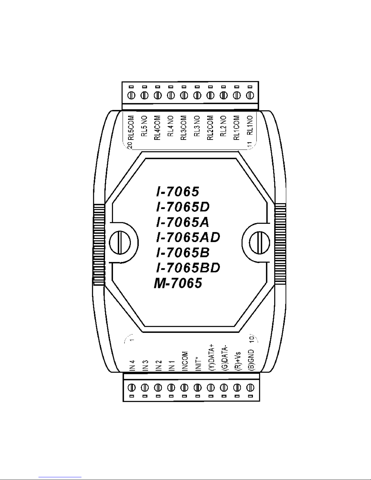
1.2 Pin Assignment
M-7065 User’s Manual Ver2.0, Dec. /2008 ---7
Page 8
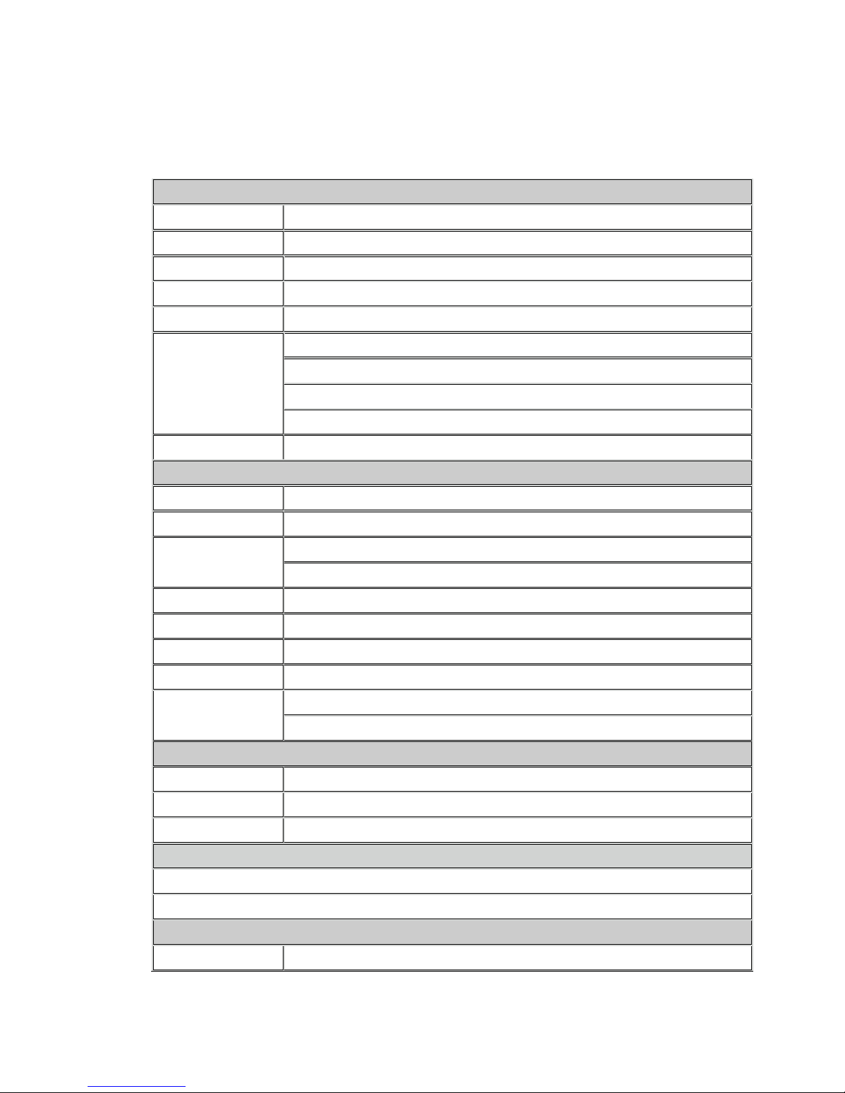
AC: 250V @5A
1.3 Specifications
Digital Input
Channels 4
Input Type Sink, Source, isolated channels with common ground or power
Off Voltage Level +1V max.
On Voltage Level +4 to +30V
Input Impedance 3K Ohms, 0.5W
channels : 4
Counters
Photo-Isolation 3750Vrms
Relay Output
Channels 5
Relay Type Form "A” relay SPST (N.O.)
Contact Rating
Operating Time(Max.) 6ms
Release Time(Min.) 3ms
Surge Strength 4,000VAC
Insulation Resistance 1000MOhms min. at 500VDC
Life Time
Interface
Max. Counters : 16-bit (65535)
Max. Input Frequency : 100Hz
Min. Pulse Width : 5ms
DC: 30V @5A
Mechanical : 20 X 10^6 OPS
Electrical : 100 X 10^3 Full Load
Interface RS-485
Format N, 8, 1 / N, 8, 2 / E 8, 1 / O 8, 1
Baud Rate 1200 ~ 115200bps
LED Display
1 LED as Power/ Communication indicator
4 LEDs as Digital Input indicators and 5 LEDs as Relay Output indicators (for I-7065D)
Power
Input Voltage Range 10~30VDC
M-7065 User’s Manual Ver2.0, Dec. /2008 ---8
Page 9
Power Consumption 1.3W (max.)(I-7065) / 1.3W (max.)(I-7065D)
Environment
Operating Temperature -25 to 75°C
Storage Temperature -40 to 85°C
Humidity 5 to 95%, non-condensing
Ordering information
M-7065 4-channel Isolated Digital Input and 5-channel Relay Output Module with 16-bit Counters
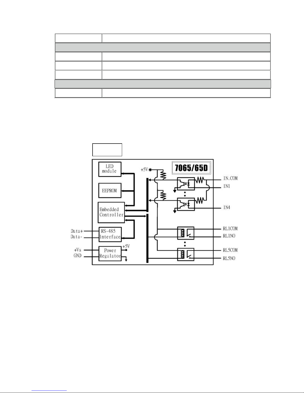
1.4 Block Diagram
M-7065
M-7065 User’s Manual Ver2.0, Dec. /2008 ---9
Page 10
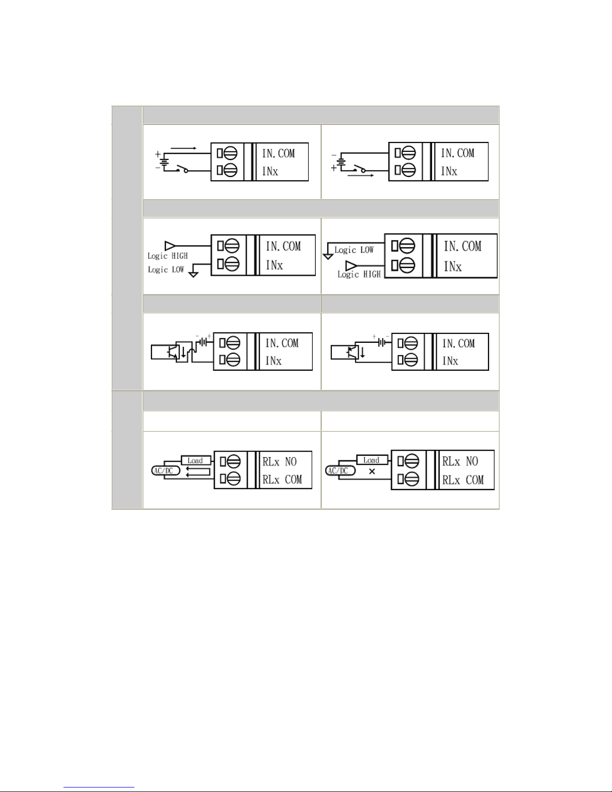
1.5 Wire Connection
Output
Dry Contact
Input
Type
Type
TTL/CMOS
NPN Output PNP Output
Relay Collector
Relay ON Relay OFF
M-7065 User’s Manual Ver2.0, Dec. /2008 ---10
Page 11

1.6 Quick Start
This Quick Start document describes the methods used to quickly set up
and test the M-7065 using the ICP DAS DCON Utility. After confirming
that the module is operational, more applications or software support be
found by referring to the following links:
For Win32:
ftp://ftp.icpdas.com/pub/cd/8000cd/napdos/driver/dcon_utility/
For Linux:
ftp://ftp.icpdas.com/pub/cd/8000cd/napdos/driver/dcon_linux/
SDK tool:
Active X: ftp://ftp.icpdas.com/pub/cd/8000cd/napdos/driver/dcon_activex/
DDE server: ftp://ftp.icpdas.com/pub/cd/8000cd/napdos/driver/dcon_dde/
DLL: ftp://ftp.icpdas.com/pub/cd/8000cd/napdos/driver/dcon_dll/
Indusoft: ftp://ftp.icpdas.com/pub/cd/8000cd/napdos/driver/dcon_indusoft/
Labview: ftp://ftp.icpdas.com/pub/cd/8000cd/napdos/driver/dcon_labview/
Loading the DCON Utility
1. The required installation file can be downloaded from:
ftp://ftp.icpdas.com/pub/cd/8000cd/napdos/driver/dcon_utility/setup/
More information related to about version numbers and the latest supported
modules can be obtained from
ftp://ftp.icpdas.com/pub/cd/8000cd/napdos/driver/dcon_utility/
M-7065 User’s Manual Ver2.0, Dec. /2008 ---11
Page 12
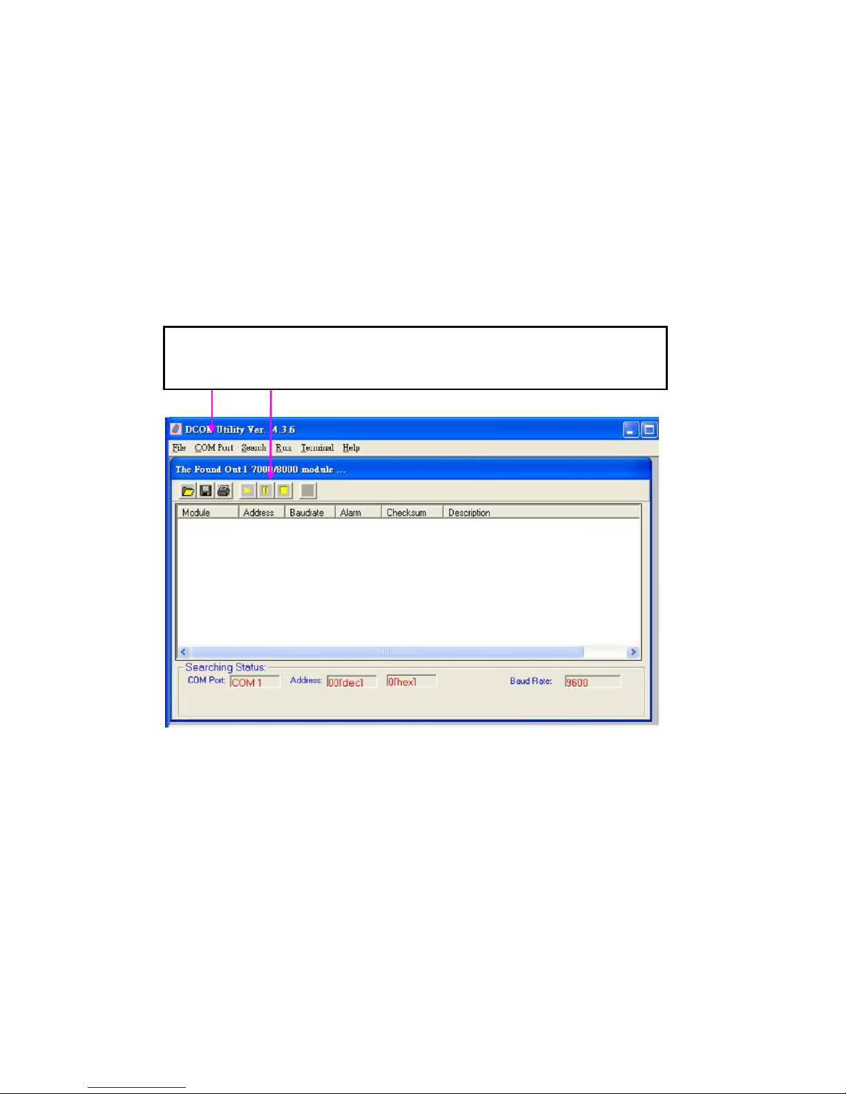
Setting up and testing the module
for connected
modules,
data
logs,
etc.
1. After installing the DCON Utility, there will be a shortcut icon for the DCON
Utility located on the Windows desktop. Double click this icon to launch
the DCON Utility to set the module’s configuration to fit with your
application. After double clicking the icon, the following screen will be
shown:
The tool bars are used to set the COM port environment, search
The tool bars are used to set the COM port environment, search for
connected modules, data logs, etc.
All ICPDAS I/M-7000 modules supported by the
current version of the DCON utility software that
are currently connected
will be listed in this area.
to
the RS-485 network
M-7065 User’s Manual Ver2.0, Dec. /2008 ---12
Page 13
How do I set the configuration of the modules ?
ICP DAS M-7065 DIO module are command based. A series of
commands are provided to allow the configuration and DI/O
functions to be set. The basic DI/O and configuration commands are
listed below. Refer to the following links for more information.
ftp://ftp.icpdas.com/pub/cd/8000cd/napdos/7000/manual/modbusdio.pdf
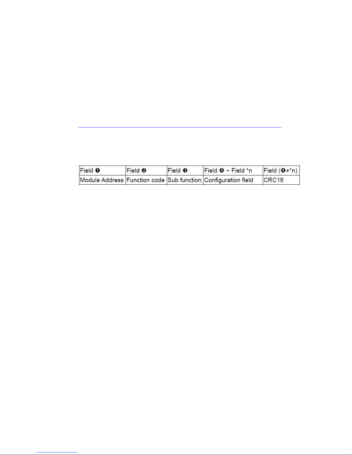
The Configuration command structure of the Modbus RTU is as
follows:
*n: This value depends on the Sub-function code. Please refer to the
“Modbus DIO User’s Manual” for more details.
Ex: To modify the power-on value of the module from 01, the
following command should be sent:
01 46 27 0F BB F9
The supported DI/O commands are as follows:
Function code Description
0x01 Read coils
0x02 Read discrete inputs
0x03 Read multiple registers
0x04 Read multiple input registers
0x05 Write single coils
0x0F Write multiple coils
M-7065 User’s Manual Ver2.0, Dec. /2008 ---13
Page 14

Ex: To read the current DI value of channels 0 to 5, the following
command should be sent:
01 02 00 00 00 05 B8 09
Ex: To write the DO value 0x0F from channels 0 to 4, the following
command should be sent:
01 0F 00 00 00 04 01 FF 7E D6
Ex: To only set the DO value of channel 2 to 1, the following
command should be sent:
01 05 00 02 FF 00 2D FA
The Configuration command structure of the Modbus ASCII is
as follows:
Command Format:
Leading
Character
Module
Address
Command
[LRC] CR LF
Response Format:
Leading
Module
Data [LRC] CR LF
Character
Using Modbus ASCII Protocol, all command are coded in
hexadecimal values, represented with readable ASCII characters.
Only the characters 0...9 and A...F are used for coding.
Address
M-7065 User’s Manual Ver2.0, Dec. /2008 ---14
Page 15

Using Modbus ASCII Protocol, characters are used to start and
end a frame. The Leading Character ':' is used to flag the start of a
command and each command is ended with a CR•LF combination.
The LRC characters are appended to the command preceding the
CR•LF characters.
LRC Calculation:
All characters except for Leading Character (:) and delimiter
(CR•LF) are added with a carry being discarded. Total value is
converted to binary notation, is converted to 2’s complements, then
to hexadecimal figures, that is, LRC.
Example :
Modbus RTU => 01 46 00 [ 12 60 ]
Modbus ASCII => :014600B9(CR•LF)
(1.) hexadecimal = 01h+46h+00h = 47h
(2.) 2’s complement: = B9h (LRC)
Technical Support
If you have problems about using the M-7065 DIO module,
please contact ICP DAS Product Support.
Email: [email protected]
M-7065 User’s Manual Ver2.0, Dec. /2008 ---15
Page 16

1.7 Default Settings
Default settings for the M-7065 modules are as follows:
Protocol:DCON
Module Address
Baud Rate:9600 bps,n,8,1
Checksum:Disabled
:01
1.8 Configuration Tables
Baud
Rate Setting
7
Parity Baud Rate Code
6 5 4 3 2 1 0
Parity (bit6~bit7)
Code
00 01 10 11
(CC)
Parity
n,8,1 n,8,2 e,8,1 o,8,1
Baud Rate Code (bit0~bit5)
Code
Baud
Rate
03 04 05 06 07 08 09 0A
1200 2400 4800 9600 19200 38400 57600 115200
Type Code (TT)
For M-7065 DIO modules, the type code is fixed to 40
M-7065 User’s Manual Ver2.0, Dec. /2008 ---16
Page 17
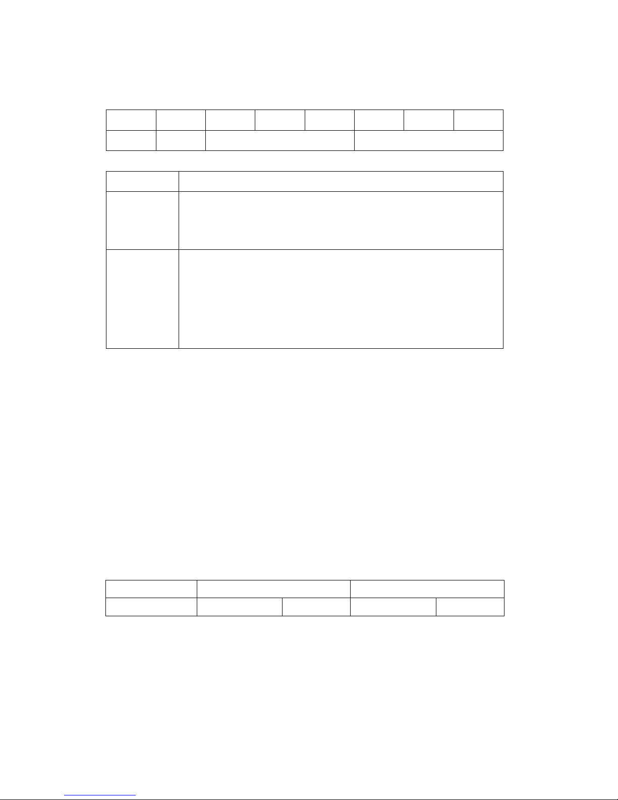
Data Format Setting (FF)
7
CU
Key Description
CS
CU
6 5 4 3 2 1 0
CS
Checksum Setting
0: Disable
1: Enable
Count Update
0: The counter is updated when there is a falling edge in
the input signal.
1: The counter is updated when there is a rising edge in
the input signal.
reserved
Note: The reserved bits should be zero.
1.9 DI/O Data Format Table
reserved
The data format of the response of the $AA4, $AA6 and
$AALS commands is:
(the First Data)(the Second Data)00.
The data format of the response of the @AA commands is:
(the First Data)(the Second Data).
Note: both the First Data and the Second Data are in
two hexadecimal digits format.
Module The First Data The Second Data
M-7065 DO0-DO5 00~1F DI0-DI3 00~0F
M-7065 User’s Manual Ver2.0, Dec. /2008 ---17
Page 18

2. DCON Protocol
All communication with M-7000 modules consists of
commands generated by the host and responses transmitted
by the M-7000 modules. Each module has a unique ID
number that is used for addressing purposes and is stored in
non-volatile memory. The ID is 01 by default and can be
changed using a user command. All commands to the
modules contain the ID address, meaning that only the
addressed module will respond. The only exception to this is
commands #**(Section 2.2) and ~** (Section 2.26), which
are sent to all modules, but in both of these cases, the
modules do not reply to the command.
Command Format:
Leading
Module
Command [CHKSUM] CR
Character
Address
Response Format:
Leading
Character
CHKSUM 2-character checksum which is present when
the checksum setting is enabled.See Sections
1.1 (Data Format Setting) for details.
CR End of command character, carriage return
(0x0D)
Module
Data [CHKSUM] CR
Address
M-7065 User’s Manual Ver2.0, Dec. /2008 ---18
Page 19

Checksum Calculation:
1. Calculate the ASCII code sum of all the characters in the
command/response string except for the carriage return
character (CR).
2. The checksum is equal to the sum masked by 0FFh.
Example:
Command string: $012(CR)
1. Sum of the string = “$”+”0”+”1”+”2” =
24h+30h+31h+32h = B7h
2. Therefore the checksum is B7h, and so
CHKSUM = “B7”
3. The command string with the checksum = $012B7(CR)
Response string: !01200600(CR)
1. Sum of the string =
“!”+”0”+”1”+”2”+”0”+”0”+”6”+”0”+”0” =
21h+30h+31h+32h+30h+30h+36h+30h+30h = 1AAh
2. Therefore the checksum is AAh, and so
CHKSUM = “AA”
3. The response string with the checksum
= !01200600AA(CR)
Note:
All characters should be in upper case.
M-7065 User’s Manual Ver2.0, Dec. /2008 ---19
Page 20
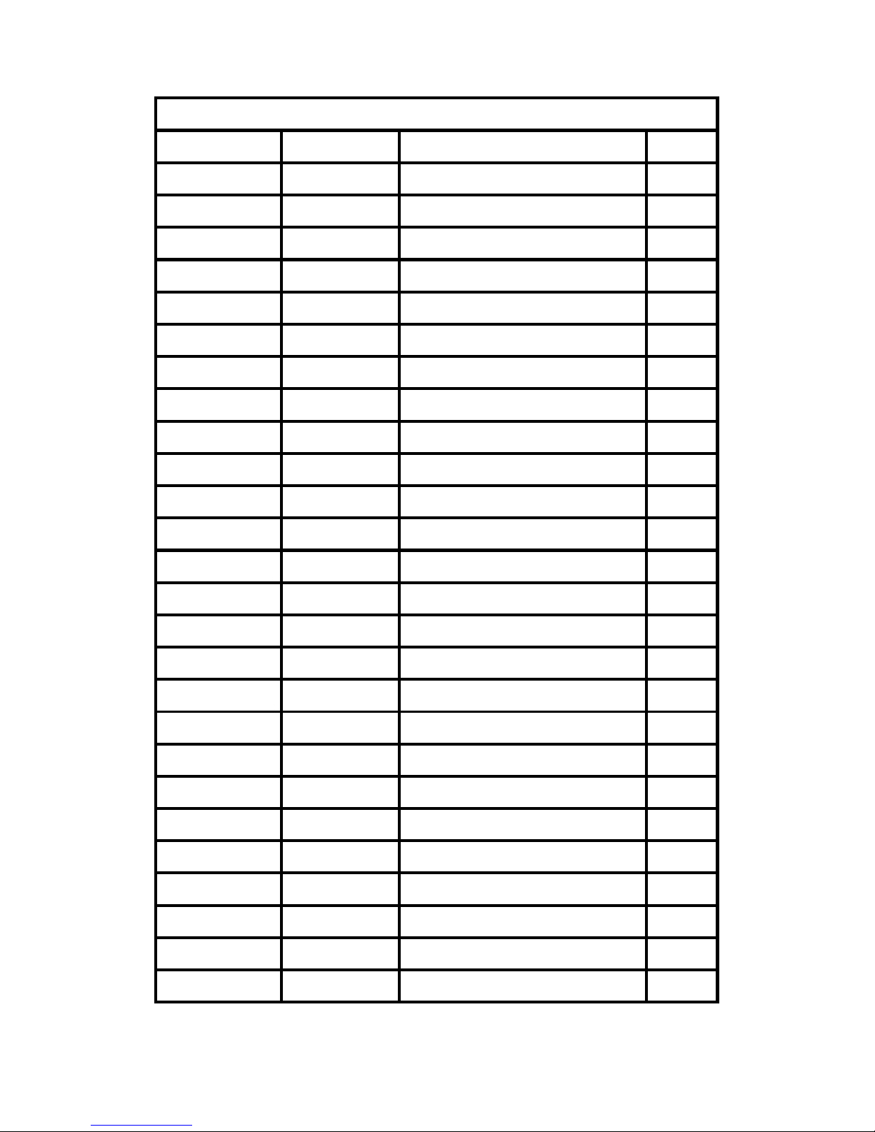
Gen era l Co mm an d Se ts
Com man d Re sp on se Des cr ip tio n Sec ti on
%AANNTTCCFF !AA Sets the Module Configuration
#** No Response Synchronized Sampling
#AA00(Data) > Sets the Digital Output
#AA0A(Data) > Sets the Digital Output
#AA1cDD > Sets the Digital Output
#AAAcDD > Sets the Digital Output
#AAN !AA(Data) Reads the Digital Input Counter
$AA2 !AANNTTCCFF Reads the Module Configuration
$AA4 !S(Data) Reads the Synchronized Data
$AA5 !AAS Reads the Reset Status
$AA6 !(Data) Reads the Digital I/O Status
$AAC !AA Clears the Latched DI Status
$AACN !AA Clears the Digital InputCounter
2.1
2.2
2.3
2.4
2.5
2.6
2.7
2.8
2.9
2.10
2.11
2.12
2.13
$AAF !AA(Data) Reads the firmware Version
$AALS !(Data) Reads the Latched DI Status
$AAM !AA(Data) Reads the Module Name
$AAP !AASC Reads the communication protocol
$AAPN !AA Sets the communication protocol
@AA >(Data) Reads the Digital I/O Status
@AA(Data) > Sets the Digital Output Channels
~AAO(Name) !AA Sets the Module Name
~AAD !AAF Reads the DI/O active status.
~AADVV !AA Sets the DI/O active status.
~AAI !AA Sets the soft INIT
~AATnn !AA Set the soft INIT timeout value
2.14
2.15
2.16
2.17
2.18
2.19
2.20
2.21
2.22
2.23
2.24
2.25
M-7065 User’s Manual Ver2.0, Dec. /2008 ---20
Page 21
Host W at ch do g Co mma nd S ets
Com man d Re sp on se D es cr ip ti on Sec ti on
~** No Response Host OK
~AA0 !AASS Reads the Status
~AA1 !AA Resets the Status
~AA2 !AAVV Reads the Timeout Settings
~AA3EVV !AA Sets the Timeout Settings
~AA4V !AA(Data) Reads the PowerOn/Safe Value
~AA5V !AA Sets the PowerOn/Safe Value
~AARDvv !AA Sets the Response Delay Time
~AARD !AA(Data) Reads the Response Delay Time
2.26
2.27
2.28
2.29
2.30
2.31
2.32
2.33
2.34
M-7065 User’s Manual Ver2.0, Dec. /2008 ---21
Page 22

2.1 %AANNTTCCFF
Description:
Sets the configuration of a module.
Syntax:
%AANNTTCCFF[CHKSUM](CR)
% Delimiter character
AA Address of the module to be configured in
hexadecimal format (00 to FF)
NN New address of the module in hexadecimal
format (00 to FF)
TT Type code, should be 40 for DIO module.
CC (Baud Rate code, should be 0A for DIO)
FF Used to set the counter update direction and
checksum (Section 1.1).
Response:
Valid Command: !AA[CHKSUM](CR)
Invalid Command: ?AA[CHKSUM](CR)
! Delimiter for a valid command.
? Delimiter for an invalid command.
AA Address of the module in hexadecimal
format (00 to FF)
M-7065 User’s Manual Ver2.0, Dec. /2008 ---22
Page 23

There will be no response if the command syntax is
incorrect, there is a communication error, or there is
no module with the specified address.
Examples:
Command:%0101400A80
Response:!01
Sets the counter update (Rising Edge)
FF (Sets the counter update)
80 : Sets the counter update (Rising Edge)
00 : Sets the counter update (Falling Edge)
Command:%0101400A00
Response:!01
Sets the counter update (Falling Edge)
FF (Sets the counter update)
80 : Sets the counter update (Rising Edge)
00 : Sets the counter update (Falling Edge)
Related Commands:
Section 2.8 $AA2、2.24 ~AAI、2.25 ~AATnn
Related Topics:
Section 1.1 Configuration Tables
M-7065 User’s Manual Ver2.0, Dec. /2008 ---23
Page 24

2.2 #**
Description:
When the command is received, it will allow all modules
to read data and will store the data for later retrieval.
Syntax:
#**[CHKSUM](CR)
# Delimiter character
** Synchronized sampling command
Response:
There is no response with this command. To access the
data, another command, $AA4, must be sent, see Section
2.11 for details.
Examples:
Command:#**
Response: No response
Sends the synchronized sampling command.
Command:$014
Response:!10C0300
M-7065 User’s Manual Ver2.0, Dec. /2008 ---24
Page 25

Sends a command to read the synchronized data.
The status byte of the response is 1, which means
that it is the first time the synchronized data has
been read after the previous #** command.
Digital Output : 0x0C
Digital Input : 0x03
Command:$014
Response:!00C0300
Sends a command to read the synchronized
data. The status byte of the response is 0,
which means that it is NOT the first time the
synchronized data has been read after the
previous #** command.
Digital Output : 0x0C
Digital Input : 0x03
Related Commands:
Section 2.9 $AA4
M-7065 User’s Manual Ver2.0, Dec. /2008 ---25
Page 26

2.3 #AA00(Data)
Description:
Sets the digital output value of the lower eight channels.
(DO0-DO7)
Syntax:
#AA00(Data)[CHKSUM](CR)
# Delimiter character
AA Address of the module to be set (00 to FF)
00 Command to set the digital output value of
the lower eight channels. (DO0-DO7)
(Data) A two-digit hexadecimal value, where bit 0
corresponds to DO0, bit 1 corresponds to
DO1, etc. When the bit is 1, it denotes that
the digital output channel is on, and 0
denotes that the digital output channel is off.
Response:
Valid Command: >[CHKSUM](CR)
Invalid Command: ?AA[CHKSUM](CR)
Ignored Command: 
> Delimiter for a valid command.
? Delimiter for an invalid command.
! Ignored Delimiter character.
M-7065 User’s Manual Ver2.0, Dec. /2008 ---26
Page 27

A host watchdog timeout has occurred, the
digital output channel s are set to safe value,
and the digital output value that was sent is
ignored.
There will be no response if the command syntax is
incorrect, there is a communication error, or there is
no module with the specified address.
Examples:
Command:#010006
Response:>
Sets DO0、 DO3 to off, DO1、DO2 to on, and
the module returns a valid response.
Command:#010016
Response:>
Sets DO0、DO3 to off,DO1、DO2 to on
DO6、DO7、 DO8 to off,DO5 to on
Command:#010005
Response:!
Host Watchdog Timeout.
M-7065 User’s Manual Ver2.0, Dec. /2008 ---27
Page 28

Related Commands:
Section
2.4 #AA0A(Data)、2.5 #AA1cDD
2.6#AAAcDD、2.11 $AA6、2.19 @AA
2.20 @AA(Data)
M-7065 User’s Manual Ver2.0, Dec. /2008 ---28
Page 29

2.4 #AA0A(Data)
Description:
Sets the digital output value.(DO0-DO31)
Syntax:
#AA0A(Data)[CHKSUM](CR)
# Delimiter character
AA Address of the module to be set (00 to FF)
0A Command to set the digital output value.
(DO0-DO31)
#AA0A(Data) : DO0-DO7
#AA0B(Data) : DO8-DO15
#AA0C(Data) : DO16-DO23
#AA0D(Data) : DO24-DO31
(Data) A two-digit hexadecimal value, where bit 0
corresponds to DO0, bit 1 corresponds to
DO1, etc. When the bit is 1, it denotes that
the digital output channel is on, and 0
denotes that the digital output channel is off.
M-7065 User’s Manual Ver2.0, Dec. /2008 ---29
Page 30

Response:
Valid Command: >[CHKSUM](CR)
Invalid Command: ?AA[CHKSUM](CR)
Ignored Command: 
> Delimiter for a valid command.
? Delimiter for an invalid command.
! Ignored Delimiter character
watchdog timeout has occurred, the digital
output channel s are set to safe value, and the
digital output value that was sent is ignored.
There will be no response if the command syntax is
incorrect, there is a communication error, or there is
no module with the specified address.
Examples:
Command:#010A0E
Response:>
Sets DO0 to off,DO1、DO2、DO3 to on.
Command:#010A06
Response:!
Host Watchdog Timeout.
M-7065 User’s Manual Ver2.0, Dec. /2008 ---30
Page 31

Command:#010A0F
Section
Response:>
Sets DO0、 DO1、DO2、DO3 to on.
Command:#020A00
Response:>
Sets DO0、 DO1、DO2、DO3 to off.
Related Commands:
2.3 #AA00(Data)、2.5 #AA1cDD
2.6#AAAcDD、2.11 $AA6、2.19 @AA
2.20 @AA(Data)
M-7065 User’s Manual Ver2.0, Dec. /2008 ---31
Page 32

2.5 #AA1cDD
Description:
Sets a single digital output channel of the lower eight
channels.
Syntax:
#AA1cDD [CHKSUM](CR)
# Delimiter character
AA Address of the module to be set (00 to FF)
1 Command to set a single digital output
channel of the lower eight channels.
c Specifies the digital output channel to be set
(0 to 7).
DD 00 : set the digital output channel to off.
01 : set the digital output channel to on.
Response:
Valid Command: >[CHKSUM](CR)
Invalid Command: ?AA[CHKSUM](CR)
Ignored Command: 
> Delimiter for a valid command.
? Delimiter for an invalid command.
! Ignored Delimiter character
M-7065 User’s Manual Ver2.0, Dec. /2008 ---32
Page 33

watchdog timeout has occurred, the digital
Section
output channel s are set to safe value, and the
digital output value that was sent is ignored.
There will be no response if the command syntax is
incorrect, there is a communication error, or there is
no module with the specified address.
Examples:
Command:#021001
Response:>
Sets DO0 to on.
Command:#021401
Response:>
Command:#021301
Response:>
Sets DO3 to on.
Related Commands:
2.3 #AA00(Data)、2.4 #AA0A(Data)
2.6#AAAcDD、2.11 $AA6、2.19 @AA
2.20 @AA(Data)
M-7065 User’s Manual Ver2.0, Dec. /2008 ---33
Page 34

2.6 #AAAcDD
Description:
Sets a single digital output channel. (DO0-DO31)
Syntax:
#AAAcDD [CHKSUM](CR)
# Delimiter character
AA Address of the module to be set (00 to FF)
A Command to set a single digital output
channel. (DO0-DO31)
#AAAcDD : DO0-DO7
#AABcDD : DO8-DO15
#AACcDD : DO16-DO23
#AADcDD : DO24-DO31
c Specifies the digital output channel to be set.
(0-7)
DD 00 : set the digital output channel to off.
01 : set the digital output channel to on.
Response:
Valid Command: >[CHKSUM](CR)
Invalid Command: ?AA[CHKSUM](CR)
Ignored Command: 
M-7065 User’s Manual Ver2.0, Dec. /2008 ---34
Page 35

> Delimiter for a valid command.
Section
? Delimiter for an invalid command.
! Ignored Delimiter character
watchdog timeout has occurred, the digital
output channel s are set to safe value, and the
digital output value that was sent is ignored.
There will be no response if the command syntax is
incorrect, there is a communication error, or there is
no module with the specified address.
Examples:
Command:#02A201
Response:>
Sets DO2 to on
Related Commands:
2.3 #AA00(Data)、2.4 #AA0A(Data)
2.5 #AA1cDD、2.11 $AA6、2.19 @AA
2.20 @AA(Data)
M-7065 User’s Manual Ver2.0, Dec. /2008 ---35
Page 36

2.7 #AAN
Description:
Reads the digital input counter of channel N.
Syntax:
#AAN [CHKSUM](CR)
# Delimiter character
AA Address of the module to be set (00 to FF)
N The channel to be read (0 to F)
Response:
Valid Command: !(Data)[CHKSUM](CR)
Invalid Command: ?AA[CHKSUM](CR)
! Delimiter for a valid command.
? Delimiter for an invalid command.
An invalid command is returned if the
specified channel is incorrect.
(Data) Five decimal digits representing the digital
input counter data of the specified channel
(00000 to 65535).
AA Address of the responding module (00 to FF)
M-7065 User’s Manual Ver2.0, Dec. /2008 ---36
Page 37

There will be no response if the command syntax is
incorrect, there is a communication error, or there is
no module with the specified address.
Examples:
Command:#011
Response:!0100005
Reads data from channel 1 of module 01 and the
returned counter value is 00005.
Command:#015
Response:!0100005
Reads data from channel 5 of module 01 and the
returned counter value is 00005.
Related Commands:
Section 2.13 #AACN
M-7065 User’s Manual Ver2.0, Dec. /2008 ---37
Page 38

2.8 $AA2
Description:
Reads the module configuration.
Syntax:
$AAN [CHKSUM](CR)
$ Delimiter character
AA Address of the module to be set (00 to FF)
2 Command to read the module configuration
Response:
Valid Command: !AATTCCFF[CHKSUM](CR)
Invalid Command: ?AA[CHKSUM](CR)
! Delimiter for a valid command.
? Delimiter for an invalid command.
AA Address of the responding module (00 to FF)
TT Type code of the module, should be 40 for
DIO module.
CC Baud Rate code of the module,should be 0A
FF Checksum and counter update direction
settings of the module, see Section 1.1 for
details.
M-7065 User’s Manual Ver2.0, Dec. /2008 ---38
Page 39

There will be no response if the command syntax is
incorrect, there is a communication error, or there is
no module with the specified address.
Examples:
Command:$012
Response:!01400A80
Reads the configuration of module 01.
FF (Sets the counter update)
80 : Reads the counter update (Rising Edge)
00 : Reads the counter update (Falling Edge)
Command:$012
Response:!01400AC0
Reads the configuration of module 01.
FF (Sets the counter update)
C0 : Reads the counter update (Rising Edge),
checksum enabled.
Related Commands:
Section 2.1 %AANNTTCCFF
Related Topics:
Section 1.1
M-7065 User’s Manual Ver2.0, Dec. /2008 ---39
Page 40

2.9 $AA4
Description:
Reads the synchronized data that was retrieved by the
last #** command.
Syntax:
$AA4 [CHKSUM](CR)
$ Delimiter character
AA Address of the module to be set (00 to FF)
4 Command to read the synchronized data
Response:
Valid
!S[CHKSUM](CR)
Command:
Invalid
?AA[CHKSUM](CR)
Command:
! Delimiter for a valid command.
? Delimiter for an invalid command.
AA Address of the responding module (00 to FF)
S Status of the synchronized data
1: first read
0: not the first read
(Data) Synchronized data. See Section 1.2 for the
data format.
M-7065 User’s Manual Ver2.0, Dec. /2008 ---40
Page 41

There will be no response if the command syntax is
incorrect, there is a communication error, or there is
no module with the specified address.
Examples:
Command:#**
Response: No response
Sends the synchronized sampling command.
Command:$014
Response:!10F0000
Reads the synchronized data for module 01.
The module returns the synchronized data and
sets the status byte to 1 to indicate that this is
the first time the synchronized data has been
read. Digital Output : 0x0F
Command:$014
Response:!0053F00
Reads the synchronized data for module 01.
The module returns the synchronized data and
sets thestatus byte to 0 to indicate that the
synchronized data has been read
Digital Output : 0x05
Digital Input : 0x3F
M-7065 User’s Manual Ver2.0, Dec. /2008 ---41
Page 42

Related Commands:
Section 2.2 #**
M-7065 User’s Manual Ver2.0, Dec. /2008 ---42
Page 43

2.10 $AA5
Description:
Reads the reset status of a module.
Syntax:
$AA5 [CHKSUM](CR)
$ Delimiter character
AA Address of the module to be set (00 to FF)
5 Command to read the module reset status.
Response:
Valid Command: !AAS[CHKSUM](CR)
Invalid Command: ?AA[CHKSUM](CR)
! Delimiter for a valid command.
? Delimiter for an invalid command.
AA Address of the responding module (00 to FF)
S Reset status of the module
1: This is the first time the command has
been sent since the module was powered on.
0: This is not the first time the command
has been sent since the module was
powered on, which denotes that there has
been no module reset since the last $AA5
command was sent.
M-7065 User’s Manual Ver2.0, Dec. /2008 ---43
Page 44

There will be no response if the command syntax is
incorrect, there is a communication error, or there is
no module with the specified address.
Examples:
Command:$015
Response:!011
Reads the reset status of module 01. The response
shows that it is the first time the $AA5 command
has been sent since the module was powered-on.
Command:$015
Response:!010
Reads the reset status of module 01. The response
shows that there has been no module reset since
the last $AA5 command was sent.
M-7065 User’s Manual Ver2.0, Dec. /2008 ---44
Page 45

2.11 $AA6
Description:
Reads the status of the digital input/output channels.
Syntax:
$AA6 [CHKSUM](CR)
$ Delimiter character
AA Address of the module to be set (00 to FF)
6 Command to read the digital input/output
channels
Response:
Valid Command: !(Data)[CHKSUM](CR)
Invalid Command: ?AA[CHKSUM](CR)
! Delimiter for a valid command.
? Delimiter for an invalid command.
AA Address of the responding module (00 to FF)
(Data) Status of the digital input/output channels, a
four- digit hexadecimal value followed by
00. See Section 1.2 for details.
There will be no response if the command syntax is
incorrect, there is a communication error, or there is
no module with the specified address.
M-7065 User’s Manual Ver2.0, Dec. /2008 ---45
Page 46

Examples:
Section
Command:$016
Response:!1F0000
Reads the digital input/output channel status of
module 01. Digital Output : 0x1F
Command:$016
Response:!070F00
Reads the digital input/output channel status of
module 01.
Digital Output : 0x07
Digital Iutput : 0x0F
Related Commands:
2.3 #AA00(Data)、2.4 #AA0A(Data)
2.5 #AA1cDD、2.6 #AAAcDD、2.19 @AA
2.20 @AA(Data)
M-7065 User’s Manual Ver2.0, Dec. /2008 ---46
Page 47

2.12 $AAC
Description:
Clears the status of the latched digital input channels.
Syntax:
$AAC [CHKSUM](CR)
$ Delimiter character
AA Address of the module to be set (00 to FF)
C Command to clear the status of the latched
digital input channels
Response:
Valid Command: !AA[CHKSUM](CR)
Invalid Command: ?AA[CHKSUM](CR)
! Delimiter for a valid command.
? Delimiter for an invalid command.
AA Address of the responding module (00 to FF)
There will be no response if the command syntax is
incorrect, there is a communication error, or there is
no module with the specified address.
M-7065 User’s Manual Ver2.0, Dec. /2008 ---47
Page 48

Examples:
Command:@016
Response:>
Sets DO1、 2 to on、DO0、3 to off
Command:$01C
Response:!01
Sends the command to clear the status of the
latched digital input channels of module 01 and
returns a valid response.
Command:$01L0
Response:!093F00
Sends the command to read the status of the low
latched digital input channels of module 01.
Low Latched DI : 0x3F
Low Latched DO : 0x09
Related Commands:
Section 2.15 $AALS
M-7065 User’s Manual Ver2.0, Dec. /2008 ---48
Page 49

2.13 $AACN
Description:
Clears the digital input counter of channel N.
Syntax:
$AACN [CHKSUM](CR)
$ Delimiter character
AA Address of the module to be set (00 to FF)
C Command to clear the digital input counter
N The channel to be cleared (0 to F).
Response:
Valid Command: !AA[CHKSUM](CR)
Invalid Command: ?AA[CHKSUM](CR)
! Delimiter for a valid command.
? Delimiter for an invalid command.
AA Address of the responding module (00 to FF)
There will be no response if the command syntax is
incorrect, there is a communication error, or there is
no module with the specified address.
M-7065 User’s Manual Ver2.0, Dec. /2008 ---49
Page 50

Examples:
Command:#011
Response:!0100009
Reads counter data from channel 1 of module 01
and the returned counter value is 00009.
Command:$01C1
Response:!01
Clears the counter value of channel 1 of module
01 and returns a valid response.
Command:#011
Response:!0100000
Reads counter data from channel 1 of module
01 and the returned counter value is 0.
Related Commands:
Section 2.7 #AAN
M-7065 User’s Manual Ver2.0, Dec. /2008 ---50
Page 51

2.14 $AAF
Description:
Reads the firmware version of a module.
Syntax:
$AAF [CHKSUM](CR)
$ Delimiter character
AA Address of the module to be set (00 to FF)
F Command to read the firmware version
Response:
Valid Command: !AA(Data)[CHKSUM](CR)
Invalid Command: ?AA[CHKSUM](CR)
! Delimiter for a valid command.
? Delimiter for an invalid command.
AA Address of the responding module (00 to FF)
(Data) Firmware version string of the module
There will be no response if the command syntax is
incorrect, there is a communication error, or there is
no module with the specified address.
M-7065 User’s Manual Ver2.0, Dec. /2008 ---51
Page 52

Examples:
Command:$01F
Response:!0102.00
Reads the firmware version of module 01, and
shows that it is version 02.00.
M-7065 User’s Manual Ver2.0, Dec. /2008 ---52
Page 53

2.15 $AALS
Description:
Reads the status of the latched digital input channels.
Syntax:
$AALS [CHKSUM](CR)
$ Delimiter character
AA Address of the module to be set (00 to FF)
L Command to read the latched status
S 0 : read the low latched status
1 : read the high latched status
Response:
Valid Command: !(Data)[CHKSUM](CR)
Invalid Command: ?AA[CHKSUM](CR)
! Delimiter for a valid command.
? Delimiter for an invalid command.
AA Address of the responding module (00 to FF)
(Data) Status of the latched digital input
channels, a four- digit hexadecimal value
followed by 00. See Section 1.2 for
details.
M-7065 User’s Manual Ver2.0, Dec. /2008 ---53
Page 54

There will be no response if the command syntax is
incorrect, there is a communication error, or there is
no module with the specified address.
Examples:
Command:@016
Response:>
Sets DO1、 2 to on、DO0、3 to off.
Command:$01C
Response:!01
Sends the command to clear the status of the
latched digital input channels of module 01 and
returns a valid response.
Command:$01L0
Response:!093F00
Sends the command to read the status of the low
latched digital input channels of module 01.
Low Latched DI : 0x3F
Low Latched DO : 0x09
M-7065 User’s Manual Ver2.0, Dec. /2008 ---54
Page 55

Command:$01L1
Response:!060000
Sends the command to read the status of the high
latched digital input channels of module 01.
High Latched DI : 0x00
High Latched DO : 0x06
Related Commands:
Section 2.12 $AAC
Related Topics:
Section 1.2
M-7065 User’s Manual Ver2.0, Dec. /2008 ---55
Page 56

2.16 $AAM
Description:
Reads the name of a module.
Syntax:
$AAM [CHKSUM](CR)
$ Delimiter character
AA Address of the module to be set (00 to FF)
M Command to read the module name
Response:
Valid Command: !AA(Data)[CHKSUM](CR)
Invalid Command: ?AA[CHKSUM](CR)
! Delimiter for a valid command.
? Delimiter for an invalid command.
AA Address of the responding module (00 to FF)
(Data) Name string of the module
There will be no response if the command syntax is
incorrect, there is a communication error, or there is
no module with the specified address.
M-7065 User’s Manual Ver2.0, Dec. /2008 ---56
Page 57

Command:$01M
Response:!017065
Reads the module name of module 01 and returns
the name.
Related Commands:
Section 2.21 ~AAO(Name)
M-7065 User’s Manual Ver2.0, Dec. /2008 ---57
Page 58

2.17 $AAP
Description:
Reads the communication protocol information.
Syntax:
$AAP [CHKSUM](CR)
$ Delimiter character
AA Address of the module to be set (00 to FF)
P Command to read the communication
protocol
Response:
Valid Command: !AASC[CHKSUM](CR)
Invalid Command: ?AA[CHKSUM](CR)
! Delimiter for a valid command.
? Delimiter for an invalid command.
AA Address of the responding module (00 to FF)
S The protocols supported by the module
0: DCON
1: DCON and Modbus RTU
3: DCON and Modbus RTU/ASCII
C The current protocol that is saved in the
EEPROM that will be used at the next
power-on reset
M-7065 User’s Manual Ver2.0, Dec. /2008 ---58
Page 59

0: DCON
1: Modbus RTU
3: Modbus ASCII
There will be no response if the command syntax is
incorrect, there is a communication error, or there is
no module with the specified address.
Examples:
Command:$01P
Response:!0130
Reads the communication protocol of module
01 and returns a response of 30 meaning that it
supports the DCON and Modbus RTU/ASCII
protocols and the protocol that will be used at
the next power-on reset is DCON.
Related Commands:
Section 2.18 $AAPN
M-7065 User’s Manual Ver2.0, Dec. /2008 ---59
Page 60

2.18 $AAPN
Description:
Sets the communication protocol.
Syntax:
$AAP [CHKSUM](CR)
$ Delimiter character
AA Address of the module to be set (00 to FF)
P Command to set the communication protocol
N 0: DCON
1: Modbus RTU
3: Modbus ASCII
Response:
Valid Command: !AA[CHKSUM](CR)
Invalid Command: ?AA[CHKSUM](CR)
! Delimiter for a valid command.
? Delimiter for an invalid command.
AA Address of the responding module (00 to FF)
There will be no response if the command syntax is
incorrect, there is a communication error, or there is
no module with the specified address.
Examples:
M-7065 User’s Manual Ver2.0, Dec. /2008 ---60
Page 61

Command:$01P1
Response:?01
Sets the communication protocol of module 01
to Modbus RTU and returns an invalid
response because the module is not in INIT
mode.
Command:$01P1
Response:!01
Sets the communication protocol of module 01
to Modbus RTU and returns a valid response.
Related Commands:
Section 2.17 $AAP
M-7065 User’s Manual Ver2.0, Dec. /2008 ---61
Page 62

2.19 @AA
Description:
Reads the status of the digital input/output ports.
Syntax:
@AA [CHKSUM](CR)
@ Delimiter character
AA Address of the module to be set (00 to FF)
Response:
Valid Command: >(Data)[CHKSUM](CR)
Invalid Command: ?AA[CHKSUM](CR)
> Delimiter for a valid command.
? Delimiter for an invalid command.
AA Address of the responding module (00 to
FF)
(Data) Status of the digital input/output ports, a
four-digit hexadecimal value. See Section 1.2
for details.
There will be no response if the command syntax is
incorrect, there is a communication error, or there is
no module with the specified address.
M-7065 User’s Manual Ver2.0, Dec. /2008 ---62
Page 63

Examples:
Section
Command:@02
Response:>0F0F
Reads the digital input/output port status of
module 02 and returns >030F, which denotes that
RL1, RL2, RL3 and RL4 are on and IN1, IN2,
IN3 and IN4 are on .
Related Commands:
2.3 #AA00(Data)、2.4 #AA0A(Data)
2.5 #AA1cDD、2.6 #AAAcDD、2.11 $AA6
2.20 @AA(Data)
Related Topics:
Section 1.2
M-7065 User’s Manual Ver2.0, Dec. /2008 ---63
Page 64

2.20 @AA(Data)
value corresponds to DO1, etc.
Description:
Sets the digital output channels.
Syntax:
@AA(Data)[CHKSUM](CR)
@ Delimiter character
AA Address of the module to be set (00 to FF)
(Data) Data to be written to the digital output
channels.
Bit 0 of the value corresponds to DO0 and
bit 1 of the
When the bit is 1, it denotes that the
digital output channel is on, and 0 denotes
that the digital output channel is off.
Response:
Valid Command: >[CHKSUM](CR)
Invalid Command: ?AA[CHKSUM](CR)
Ignored Command: 
> Delimiter for a valid command.
? Delimiter for an invalid command.
! Ignored Delimiter character
M-7065 User’s Manual Ver2.0, Dec. /2008 ---64
Page 65

watchdog timeout has occurred, the digital
output ports are set to safe value, and the
digital output value that was sent is
ignored.
There will be no response if the command syntax is
incorrect, there is a communication error, or there is
no module with the specified address.
Examples:
Command:@02F
Response:>
Sets DO0、 DO1、DO2、DO3 to on.
Related Commands:
Section 2.3 #AA00(Data)、2.4 #AA0A(Data)、
2.5 #AA1cDD、2.6#AAAcDD、2.11
$AA6、 2.19 @AA
M-7065 User’s Manual Ver2.0, Dec. /2008 ---65
Page 66

2.21 ~AAO(Name)
Description:
Sets the name of a module.
Syntax:
~AAO(Name) [CHKSUM](CR)
~ Delimiter character
AA Address of the module to be set (00 to FF)
O Command to set the module name
(Name) New name of the module (max. 6 characters)
Response:
Valid Command: !AA[CHKSUM](CR)
Invalid Command: ?AA[CHKSUM](CR)
! Delimiter for a valid command.
? Delimiter for an invalid command.
AA Address of the responding module (00 to
FF)
There will be no response if the command syntax is
incorrect, there is a communication error, or there is
no module with the specified address.
M-7065 User’s Manual Ver2.0, Dec. /2008 ---66
Page 67

Examples:
Command:$01M
Response:!017065
Reads the name of module 01 and returns the
name 7065.
Command:~01OM7065
Response:!01
Sets the name of module 01 to be “ M7065” and
returns a valid response.
Command:$01M
Response:!01M7065
Reads the name of module 01 and returns the
name M7065.
M-7065 User’s Manual Ver2.0, Dec. /2008 ---67
Page 68

2.22 ~AAD
Description:
Reads Digital I/O Active status.
Syntax:
~AAD [CHKSUM](CR)
~ Delimiter character
AA Address of the module to be set (00 to FF)
D Command to read the DI/O active status
Response:
Valid Command: !AAVV[CHKSUM](CR)
Invalid Command: ?AA[CHKSUM](CR)
! Delimiter for a valid command.
? Delimiter for an invalid command.
AA Address of the responding module (00 to
FF)
VV A two-digit hexadecimal value indicating
the DI/O active status.
There will be no response if the command syntax is
incorrect, there is a communication error, or there is
no module with the specified address.
M-7065 User’s Manual Ver2.0, Dec. /2008 ---68
Page 69
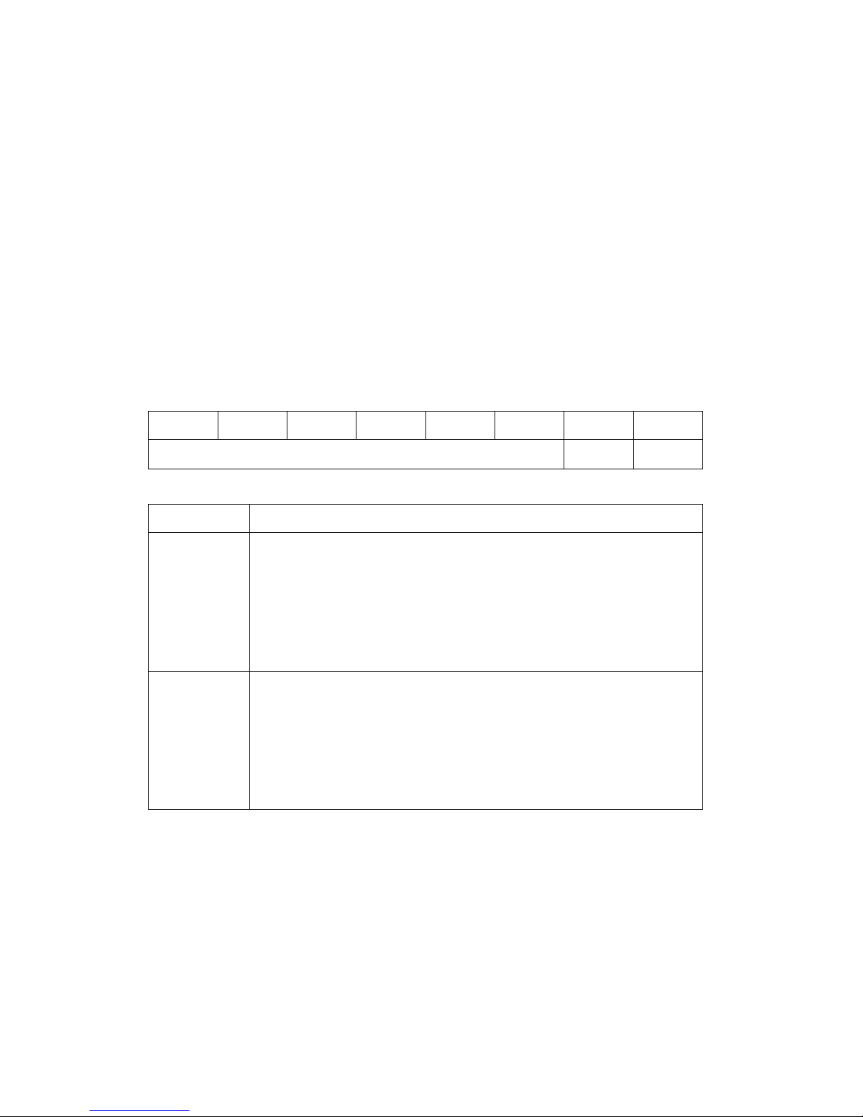
Examples:
Command:~02D03
Response:!02
Sets DI/O active status.
Command:~02D
Response:!0203
Reads DI/O active status.
7
6 5 4 3 2 1 0
Reserved
Key Description
DO Active Status
0: output value 1 for relay active
OAS
IAS
0: output value 0 for relay inactive
1: output value 0 for relay active
0: output value 1 for relay inactive
DI Active Status
0: input value 1 for non-signal or the low voltage;
0: input value 0 for high voltage
1: input value 0 for non-signal or the low voltage;
0: input value 1 for high voltage
OAS IAS
(DI/O Active Status)
Related Commands:
Section 2.23 ~AADVV
M-7065 User’s Manual Ver2.0, Dec. /2008 ---69
Page 70

2.23 ~AADVV
Description:
Sets Digital I/O Active status.
Syntax:
~AADVV [CHKSUM](CR)
~ Delimiter character
AA Address of the module to be set (00 to FF)
D Command to set the DI/O active status.
VV A two-digit hexadecimal value indicating
the DI/O active status.
Response:
Valid Command: !AA[CHKSUM](CR)
Invalid Command: ?AA[CHKSUM](CR)
! Delimiter for a valid command.
? Delimiter for an invalid command.
AA Address of the responding module (00 to
FF)
There will be no response if the command syntax is
incorrect, there is a communication error, or there is
no module with the specified address.
M-7065 User’s Manual Ver2.0, Dec. /2008 ---70
Page 71
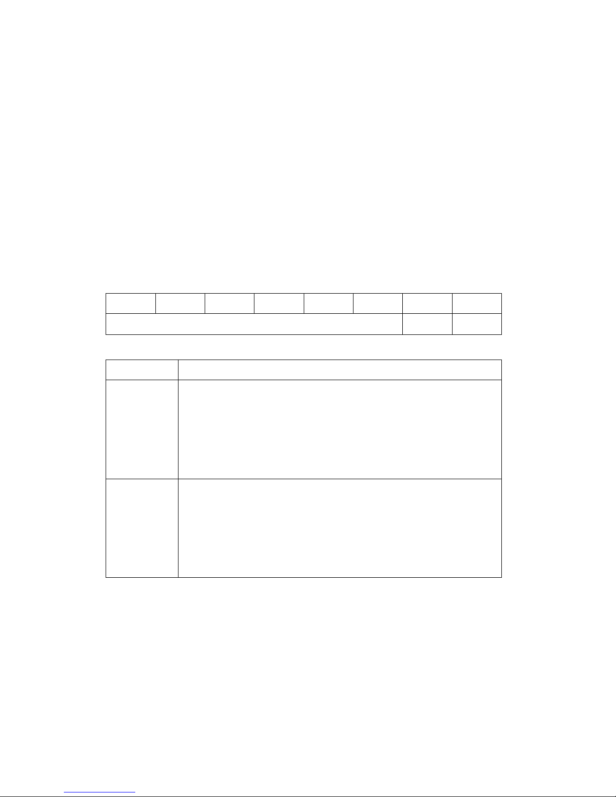
Examples:
Command:~02D03
Response:!02
Sets DI/O active status.
Command:~02D
Response:!0203
Reads DI/O active status.
7
6 5 4 3 2 1 0
Reserved
Key Description
DO Active Status
0: output value 1 for relay active
OAS
IAS
0: output value 0 for relay inactive
1: output value 0 for relay active
0: output value 1 for relay inactive
DI Active Status
0: input value 1 for non-signal or the low voltage;
0: input value 0 for high voltage
1: input value 0 for non-signal or the low voltage;
0: input value 1 for high voltage
OAS IAS
Related Commands:
Section 2.22 ~AAD
M-7065 User’s Manual Ver2.0, Dec. /2008 ---71
Page 72

2.24 ~AAI
Description:
The Soft INIT command is used to enable
modification of the Baud Rate and checksum settings
using software only.
Syntax:
~AAI [CHKSUM](CR)
~ Delimiter character
AA Address of the module to be set (00 to FF)
I Command to set the Sort INIT
Response:
Valid Command: !AA[CHKSUM](CR)
Invalid Command: ?AA[CHKSUM](CR)
! Delimiter for a valid command.
? Delimiter for an invalid command.
AA Address of the responding module (00 to
FF)
There will be no response if the command syntax is
incorrect, there is a communication error, or there is
no module with the specified address.
M-7065 User’s Manual Ver2.0, Dec. /2008 ---72
Page 73

Examples:
Command:~03I
Response:!03
Sets Soft INIT
Command:%0303400700
Response:?03
Attempts to change the Baud Rate of module
03 to 19200 without first adjusting the INIT
*pin. The module returns an invalid reponse
because the soft INIT timeout value is 0.
Command:~03T10
Response:!03
Set the soft INIT time out value of module 01
to 16 seconds and returns a valid response.
Command:~03I
Response:!03
Set the Soft INIT of module 01 and return a
valid response.
M-7065 User’s Manual Ver2.0, Dec. /2008 ---73
Page 74

Command:%0301400740
Response:!03
Attempts to change the Baud Rate of module
01 to 19200 without first adjusting the INIT *
pin.The module returns an in valid response.
Related Commands::::
Section 2.25 ~AATnn
M-7065 User’s Manual Ver2.0, Dec. /2008 ---74
Page 75

2.25 ~AATnn
Description:
Sets the soft INIT timeout value.
Syntax:
~AATnn [CHKSUM](CR)
~ Delimiter character
AA Address of the module to be set (00 to FF)
T Command to set the Sort INIT timeout
value
nn Two hexadecimal digits representing the
time out value in seconds.The maximum
timeout value is 60 seconds.
Response:
Valid Command: !AA[CHKSUM](CR)
Invalid Command: ?AA[CHKSUM](CR)
! Delimiter for a valid command.
? Delimiter for an invalid command.
AA Address of the responding module
There will be no response if the command syntax is
incorrect, there is a communication error, or there is
no module with the specified address.
M-7065 User’s Manual Ver2.0, Dec. /2008 ---75
Page 76

2.26 ~**
Description:
Informs all modules that the host is OK.
Syntax:
~** [CHKSUM](CR)
~ Delimiter character
** Host OK command
Response:
No response
Examples:
Command: ~**
Response: No response
Related Commands:
Section 2.27 ~AA0、2.28 ~AA1、 2.29 ~AA2
2.30 ~AA3EVV、2.31 ~AA4V、
2.32 ~AA5V
M-7065 User’s Manual Ver2.0, Dec. /2008 ---76
Page 77

2.27 ~AA0
Description:
Reads the host watchdog status of a module.
Syntax:
~AA0 [CHKSUM](CR)
~ Delimiter character
AA Address of the module to be set (00 to FF)
0 Command to read the module status
Response:
Valid Command: !AASS[CHKSUM](CR)
Invalid Command: ?AA[CHKSUM](CR)
! Delimiter for a valid command.
? Delimiter for an invalid command.
AA Address of the responding module (00 to
FF)
SS Two hexadecimal digits that represent the
host watchdog status, where:
Bit 7: 0 indicates that the host watchdog is
disabled, and 1 indicates that the host
watchdog is enabled,
Bit 2: 1 indicates that a host watchdog
timeout has occurred, and 0 indicates that
no host watchdog timeout has occurred.
M-7065 User’s Manual Ver2.0, Dec. /2008 ---77
Page 78

The host watchdog status is stored in
EEPROM and can only be reset by using the
~AA1 command.
There will be no response if the command syntax is
incorrect, there is a communication error, or there is
no module with the specified address.
Examples:
Command:~030
Response:!0304
Reads the host watchdog status of module 03
and returns 04, meaning that a host watchdog
timeout has occurred.
Command:~030
Response:!0300
Reads the host watchdog status of module 03
and returns 00, meaning that the host watchdog
is disabled and no host watchdog timeout has
occurred.
M-7065 User’s Manual Ver2.0, Dec. /2008 ---78
Page 79

Command:~030
Section
Response:!0380
Reads the host watchdog status of module 03
and returns 08, meaning that the host watchdog
is enabled. Sents ~** to clear watchdog timeout
value.
Related Commands:
2.26 ~**、2.28 ~AA1、2.29 ~AA2
2.30 ~AA3EVV、2.31 ~AA4V、
2.32 ~AA5V
M-7065 User’s Manual Ver2.0, Dec. /2008 ---79
Page 80

2.28 ~AA1
Description:
Resets the host watchdog timeout status of a module.
Syntax:
~AA1 [CHKSUM](CR)
~ Delimiter character
AA Address of the module to be set (00 to FF)
1 Command to reset the host watchdog timeout
status
Response:
Valid Command: !AA[CHKSUM](CR)
Invalid Command: ?AA[CHKSUM](CR)
! Delimiter for a valid command.
? Delimiter for an invalid command.
AA Address of the responding module (00 to
FF)
There will be no response if the command syntax is
incorrect, there is a communication error, or there is
no module with the specified address.
M-7065 User’s Manual Ver2.0, Dec. /2008 ---80
Page 81

Examples:
Section
Command:~030
Response:!0304
Reads the host watchdog status of module 03 and
shows that a host watchdog timeout has occurred.
Command:~031
Response:!03
Resets the host watchdog timeout status of
module 03 and returns a valid response.
Related Commands:
2.26 ~**、2.27 ~AA0、2.29 ~AA2
2.30 ~AA3EVV、2.31 ~AA4V、
2.32 ~AA5V
M-7065 User’s Manual Ver2.0, Dec. /2008 ---81
Page 82

2.29 ~AA2
Description:
Reads the host watchdog timeout value of a module.
Syntax:
~AA0 [CHKSUM](CR)
~ Delimiter character
AA Address of the module to be set (00 to FF)
2 Command to read the host watchdog timeout
value
Response:
Valid Command: !AAEVV[CHKSUM](CR)
Invalid Command: ?AA[CHKSUM](CR)
! Delimiter for a valid command.
? Delimiter for an invalid command.
AA Address of the responding module (00 to
FF)
E 1: the host watchdog is enabled
0: the host watchdog is disabled
VV Two hexadecimal digits to represent the
timeout value in tenths of a second, for
example, 01 denotes 0.1 seconds and FF
denotes 25.5 seconds.
M-7065 User’s Manual Ver2.0, Dec. /2008 ---82
Page 83

There will be no response if the command syntax is
Section
incorrect, there is a communication error, or there is
no module with the specified address.
Examples:
Command:~032
Response:!03190
Reads the host watchdog timeout value of
module 03 and returns 0x90, which denotes
that the host watchdog is enabled and the host
watchdog timeout value is 14.4 seconds
Related Commands:
2.26 ~**、2.27 ~AA0、2.28 ~AA1
2.30 ~AA3EVV、2.31 ~AA4V、
2.32 ~AA5V
M-7065 User’s Manual Ver2.0, Dec. /2008 ---83
Page 84

2.30 ~AA3EVV
Description:
Enables/disables the host watchdog and sets the host
watchdog timeout value of a module.
Syntax:
~AA3EVV [CHKSUM](CR)
~ Delimiter character
AA Address of the module to be set (00 to FF)
3 Command to set the host watchdog
E 1: enable the host watchdog
0: disable the host watchdog
VV Two hexadecimal digits to represent the
timeout value in tenths of a second, for
example, 01 denotes 0.1 seconds and FF
denotes 25.5 seconds.
Response:
Valid Command: !AA[CHKSUM](CR)
Invalid Command: ?AA[CHKSUM](CR)
! Delimiter for a valid command.
? Delimiter for an invalid command.
AA Address of the responding module (00 to
FF)
M-7065 User’s Manual Ver2.0, Dec. /2008 ---84
Page 85

There will be no response if the command syntax is
the host watchdog timeout value to 10.0 seconds.
Section
incorrect, there is a communication error, or there is
no module with the specified address.
Examples:
Command:~013164
Response:!01
Enables the host watchdog of module 01 and sets
The module returns a valid response.
Command:~012
Response:!01164
Reads the host watchdog timeout value of module
01. The module returns 164, which denotes that
the host watchdog is enabled and the host
watchdog timeout value is 10.0 seconds.
Related Commands:
2.26 ~**、2.27 ~AA0、2.28 ~AA1
2.29 ~AA2、2.31 ~AA4V、
2.32 ~AA5V
M-7065 User’s Manual Ver2.0, Dec. /2008 ---85
Page 86

2.31 ~AA4V
Description:
Reads the power-on DO value or the safe DO value of a
module.
Syntax:
~AA4V [CHKSUM](CR)
~ Delimiter character
AA Address of the module to be set (00 to FF)
4 Command to read the power-on DO value or
the safe DO value
V P: Power On Value
S: Safe Value
Response:
Valid Command: !AA(Data)[CHKSUM](CR)
Invalid Command: ?AA[CHKSUM](CR)
! Delimiter for a valid command.
? Delimiter for an invalid command.
AA Address of the responding module(00 to FF)
(Data) Power On Value or Safe Value
There will be no response if the command syntax is
incorrect, there is a communication error, or there is no
module with the specified address.
M-7065 User’s Manual Ver2.0, Dec. /2008 ---86
Page 87

Examples:
Command:~034P
Response:!030700
Reads the power-on DO value of module 03 and
returns 0700.
Command:~034S
Response:!030F00
Reads the safe DO value of module 03 and
returns 0F00.
Related Commands:
Section 2.32 ~AA5V
M-7065 User’s Manual Ver2.0, Dec. /2008 ---87
Page 88

2.32 ~AA5V
Description:
Sets the current DO value as the power-on DO value or
the safe DO value.
Syntax:
~AA5V [CHKSUM](CR)
~ Delimiter character
AA Address of the module to be set (00 to FF)
5 Command to set the power-on value or the
safe DO value
V P: Power On Value
S: Safe Value
Response:
Valid Command: !AA[CHKSUM](CR)
Invalid Command: ?AA[CHKSUM](CR)
! Delimiter for a valid command.
? Delimiter for an invalid command.
AA Address of the responding module (00 to
FF)
There will be no response if the command syntax is
incorrect, there is a communication error, or there is
no module with the specified address.
M-7065 User’s Manual Ver2.0, Dec. /2008 ---88
Page 89

Examples:
Command:@037
Response:>
Sets DO0、 DO1、DO2 to on, DO3 to off
Command:~035P
Response:!03
Sets the power-on DO value and the module
returns a valid response.
Command:@03F
Response:>
Sets DO0、 DO1、DO2、DO3 to on
Command:~035S
Response:!03
Sets the safe DO value and the module returns
a valid response.
Command:~034S
Response:!030F00
Reads the safe DO value of module 03.
Related Commands:
Section 2.31 ~AA4V
M-7065 User’s Manual Ver2.0, Dec. /2008 ---89
Page 90

2.33 ~AARDvv
Description:
Sets the Response Delay Time of a module.
Syntax:
~AARDvv [CHKSUM](CR)
$ Delimiter character
AA Address of the module to be set (00 to FF)
RD Command to set the Response Delay Time
of a module.
vv Response Delay Time (0~30,in 1ms)
Response:
Valid Command: !AA[CHKSUM](CR)
Invalid Command: ?AA[CHKSUM](CR)
! Delimiter for a valid command.
? Delimiter for an invalid command.
AA Address of the responding module (00 to
FF)
There will be no response if the command syntax is
incorrect, there is a communication error, or there is
no module with the specified address.
M-7065 User’s Manual Ver2.0, Dec. /2008 ---90
Page 91

Examples:
Command:~03RD1E
Response:!03
Sets the Response Delay Time, the value is 1E.
(30ms)
Command:~03RD
Response:!0300
Reads the Response Delay Time, the value is 00.
(0ms).
Related Commands:
Section 2.34 ~AARD
M-7065 User’s Manual Ver2.0, Dec. /2008 ---91
Page 92

2.34 ~AARD
Description:
Reads the Response Delay Time of a module.
Syntax:
~AARD [CHKSUM](CR)
~ Delimiter character
AA Address of the module to be set (00 to FF)
RD Command to read the Response Delay Time of
a module.(0~30,in 1ms)
Response:
Valid Command: !AA(Data)[CHKSUM](CR)
Invalid Command: ?AA[CHKSUM](CR)
! Delimiter for a valid command.
? Delimiter for an invalid command.
AA Address of the responding module(00 to FF)
(Data) Response Delay Time Value
There will be no response if the command syntax is
incorrect, there is a communication error, or there is no
module with the specified address.
M-7065 User’s Manual Ver2.0, Dec. /2008 ---92
Page 93

Examples:
Command:~03RD1E
Response:!03
Sets the Response Delay Time, the value is 1E.
(30ms)
Command:~03RD
Response:!0300
Reads the Response Delay Time, the value is 00.
(0ms).
Related Commands:
Section 2.33 ~AARDvv
M-7065 User’s Manual Ver2.0, Dec. /2008 ---93
Page 94
3.
Modbus
RTU Protocol
The Modbus protocol is developed by Modicon Inc.,
originally developed for Modicon controllers. Detailed
information can be found at
http://www.modicon.com/techpubs/toc7.html. You can
also visit http://www.modbus.org to find more valuable
information.
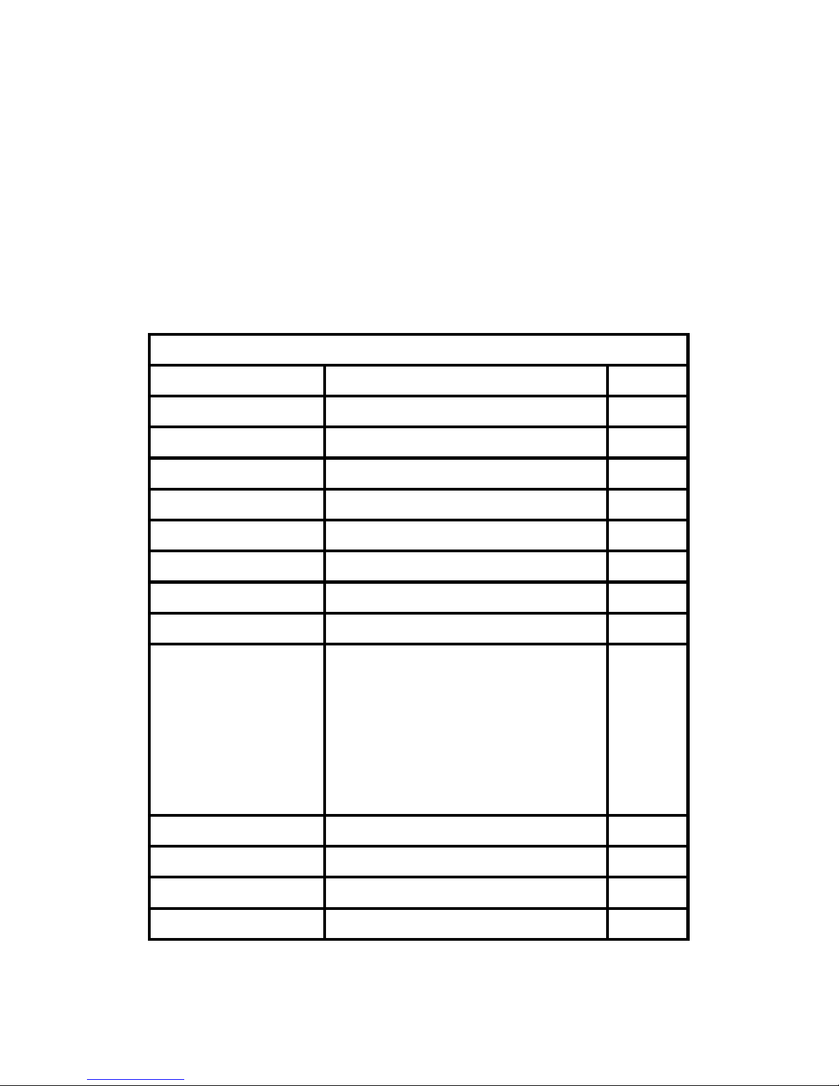
Addr es s Ma pp in g
Addr es s Des cr ip tio n Attr ib ut e
00001 Digital Output Channel
00033 Digital Input Channel
10001 Digital Input Channel
00065 High Latched DI/O Channels
00097 Low Latched DI/O Channels
00129 Safe Value
00161 Power On Value
40485 Module address, valid range:1~247
bits 5:0 (Baud rate)
Baud rate, valid range:0x03-0x0A
bits 7:6
40486
00: no parity, 1 stop bit
10: even parity, 1 stop bit
11: odd parity, 1 stop bit
R/W
R
R
R
R
R/W
R/W
R/W
R/W
00264 Clear Latched DI/O
00513 Clear DI Count
40481 Firmware version (low word)
40482 Firmware version (high word)
M-7065 User’s Manual Ver2.0, Dec. /2008 ---94
W
W
R
R
Page 95
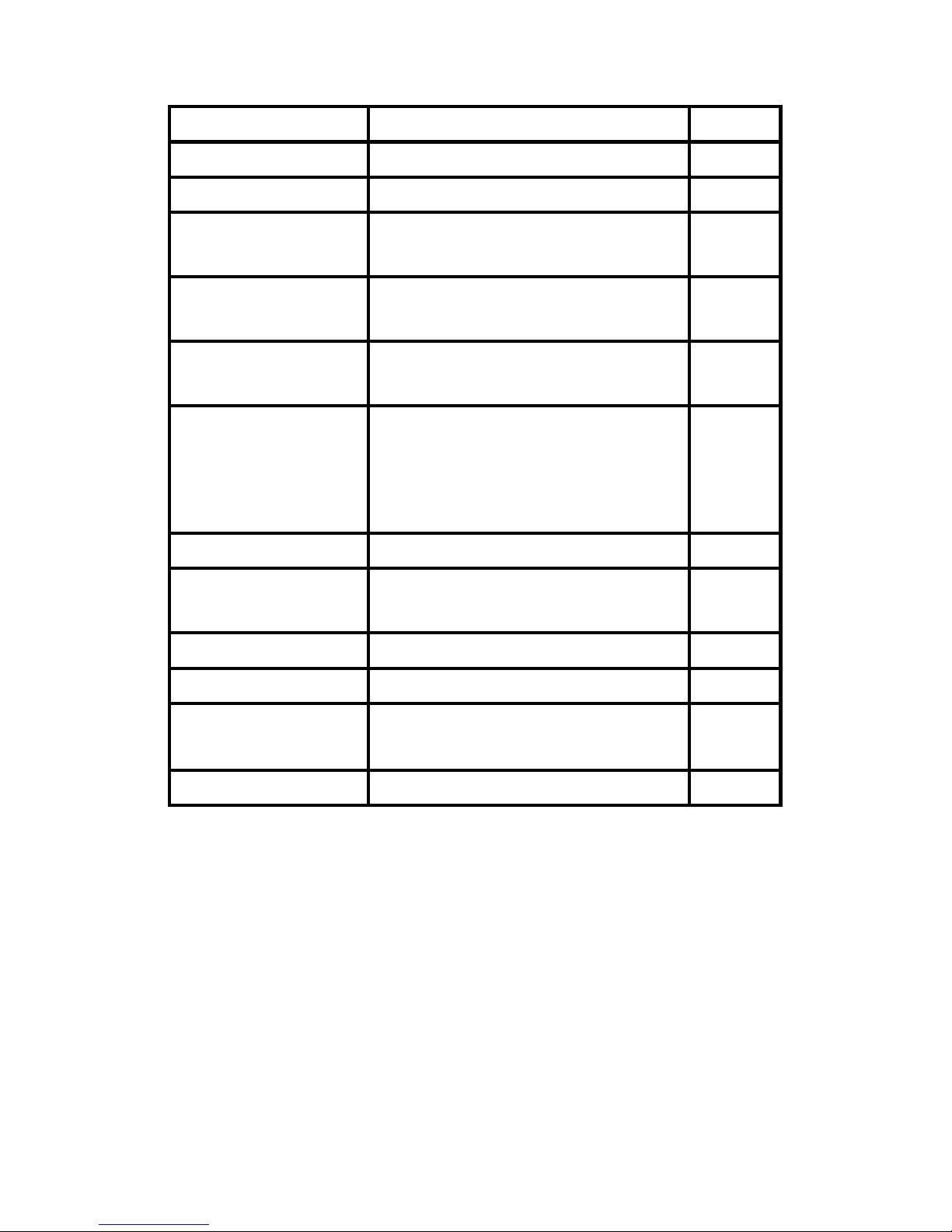
40483 Module name (low word)
R
40484 Module name (high word)
30001 DI Count Value
Host watch dog timeout status, write 1 to
00270
clear host watchdog timeout status.
Modbus reponse delay time in ms, valid
40488
range:0~30
Host watchdog timeout count,write 0 to
40492
clear
Modbus host watchdog mode
0 : same as I-7000
00260
1 : can use AO and DO command to clear
host watchdog timeout status
00261 1 : enable, 0 : disable host watchdog
Host watchdog timeout value, 0~255, in
40489
0.1s
R
R
R/W
R/W
R/W
R/W
R/W
R/W
00257
00258
10273
312345, 412345 Informs all modules that the host is OK
Protocol, 0: DCON, 1: Modbus
Modbus Protocol Option, 0: RTU, 1:ASCII
Reset status, 1: first read after powered on,
0 : not the first read after powered on
1.
Modbus RTU Function Description:
(0xxxx) : 0x01、0x05、0x0F Function code
(1xxxx) : 0x02 Function code
(3xxxx) : 0x04 Function code
(4xxxx) : 0x03、0x03、0x10 Function code
2. Address mapping of PLC(Base 1).
R/W
R/W
R
R
M-7065 User’s Manual Ver2.0, Dec. /2008 ---95
Page 96
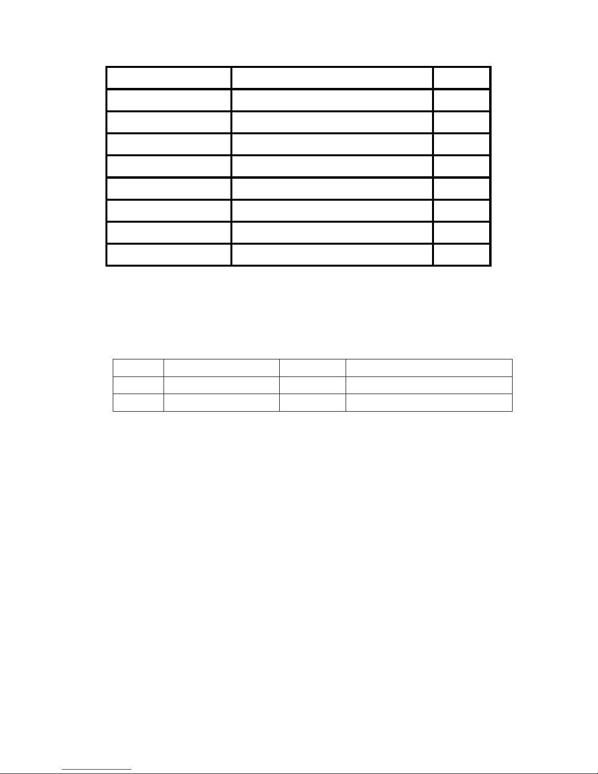
Func tion c ode Des cr ip tio n Sect io n
0x01 Read coils
0x02 Read discrete inputs
0x03 Read multiple registers
0x04 Read multiple input registers
0x05 Write single coils
0x06 Write multiple registers
0x0F Write multiple coils
0x46 Read/Write module settings
3.1
3.2
3.3
3.4
3.5
3.6
3.7
3.8
If the function specified in the message is not supported, then
the
module responds as follows. Address mapping of
Protocol(Base 0).
Error Response
00 Address 1 Byte 1 to 247
01 Function code 1 Byte Function code + 0x80
02 Exception code 1 Byte 01
If a CRC mismatch occurs, the module will not respond.
M-7065 User’s Manual Ver2.0, Dec. /2008 ---96
Page 97

3.1 01(0x01) Read coils
This function code is used to read the current
digital output readback value.
Request
00 Addr es s 1 By te 1-2 47
01 Function code 1 By te
Starting channel
02-03
numbers or address
mapping
2 B yte
0x01
DO : 0x0000-0x001F
DI : 0x0020-0x003F
DI/O Latch High :
0x0040-0x005F
DI/O Latch Low :
0x0060-0x007F
Safe Value :
0x0080-0x009F
Power On Value :
0x00A0-0x00BF
Reads WDT Mode :
0x0103
Reads WDT Enable :
0x0104
Reads WDT Status :
04-05
Output channel number
or bit count
M-7065 User’s Manual Ver2.0, Dec. /2008 ---97
0x010D
Reads Protocol : 0x0100
Reads Reset Status :
0x0110
0x0001-0x0020
2 B yte
(Bit count)
Page 98
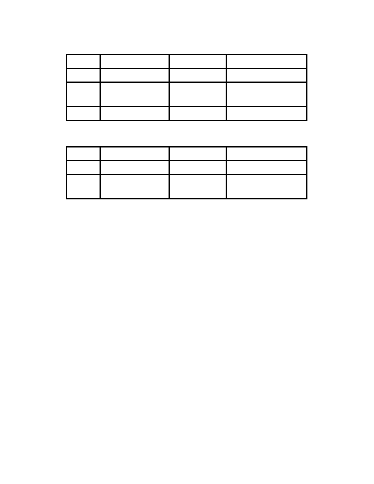
Response:
00 Addr es s 1 By te 1-2 47
01 Function code 1 By te
Byte count of response
02 Byte Count 1 Byt e
(B=(bit count + 7)/8)
03 Bit values B B yte
Error Response:
00 Addr es s 1 By te 1-2 47
01 Function code 1 By te
Refer to Modbus standard
02 Exception code 1 Byte
for more details
Examples:
Command:05 01 00 00 00 05 [ FD 8D ]
Response:05 01 01 1F 11 70
0x01
(Bit values)
0x81
Reads digital output value
[Command]
Byte 2~3 : 00 00 (starting channel numbers)
Byte 4~5 : 00 05 (output channel number)
Byte 6~7 : FD 8D(CRC)
[Response]
Byte 1 : 01 (Function Code)
Byte 2 : 01 (Byte count of response)
Byte 3 : 1F (DO0~DO3 Value)
Byte 4~5 : 11 70 (CRC)
M-7065 User’s Manual Ver2.0, Dec. /2008 ---98
Page 99

Command:05 01 00 40 00 04 [ 3D 99 ]
Response:05 01 01 07 11 7A
Reads digital input high latch
Command:05 01 01 03 00 01 [ 0D B2 ]
Response:05 01 01 00 50 B8
Reads modbus host watchdog’s mode
Command:05 01 01 10 00 01 [ FC 77 ]
Response:05 01 01 01 91 78
Reads reset status of modules
Command:05 01 01 04 00 01 [ BC 73 ]
Response:05 01 01 00 50 B8
Reads host watchdog setting (enabled or not)
Command:05 01 01 0D 00 01 [ 6C 71 ]
Response:05 01 01 00 50 B8
Resets the host watchdog timeout status of a module
Command:05 01 01 00 00 09 [ 6C 71 ]
Response:05 01 02 01 00 49 AC
Reads protocol of module
M-7065 User’s Manual Ver2.0, Dec. /2008 ---99
Page 100
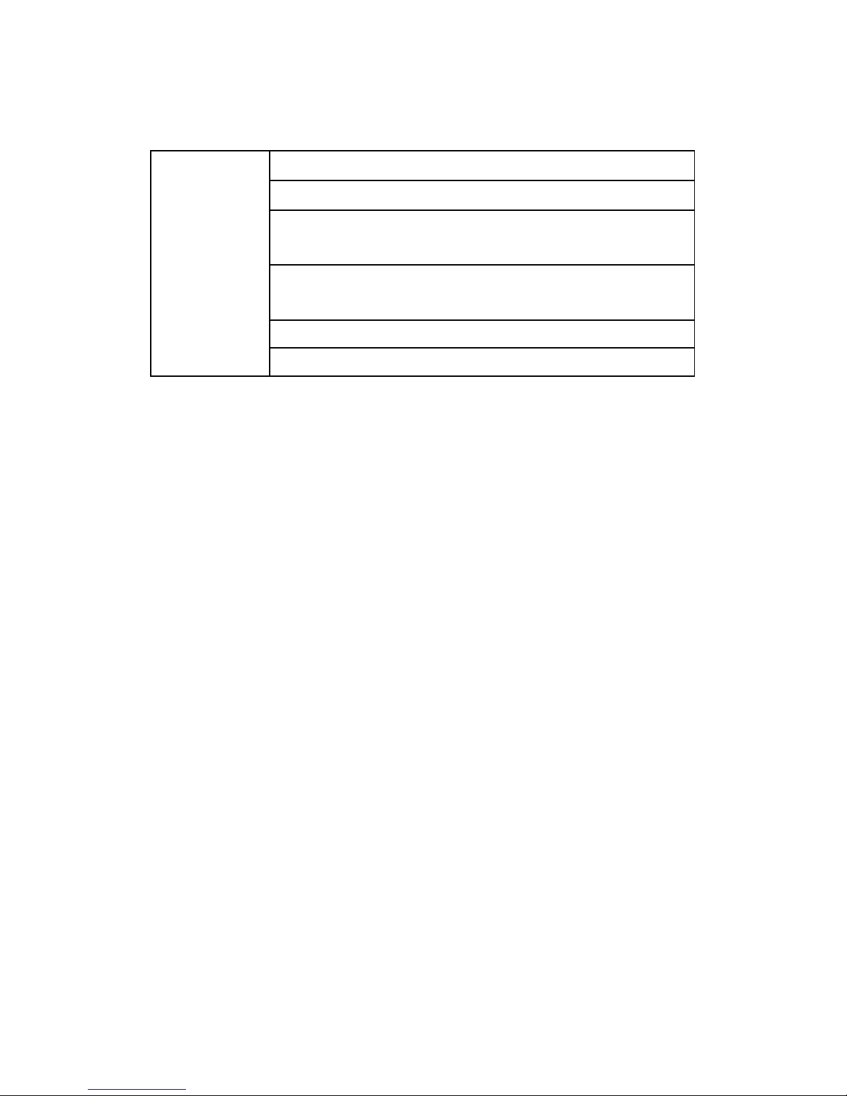
Supported modules :
M-7065
DO : 0x0 00 0~ 0x 00 04
DI : 0x0 02 0~0 x0 02 3
Valid starting
channel
High Latched DI Channel : 0x 004 0~ 0x 00 43
Low Latched DI Channel : 0x 006 0~ 0x 00 63
Safe Value : 0x 00 80~ 0x 008 4
Power On Value : 0x 00A 0~ 0x 00 A4
M-7065 User’s Manual Ver2.0, Dec. /2008 ---100
 Loading...