

Page 1
P1
IR-712A(-5) Quick Start
v1.6, Jun 2020
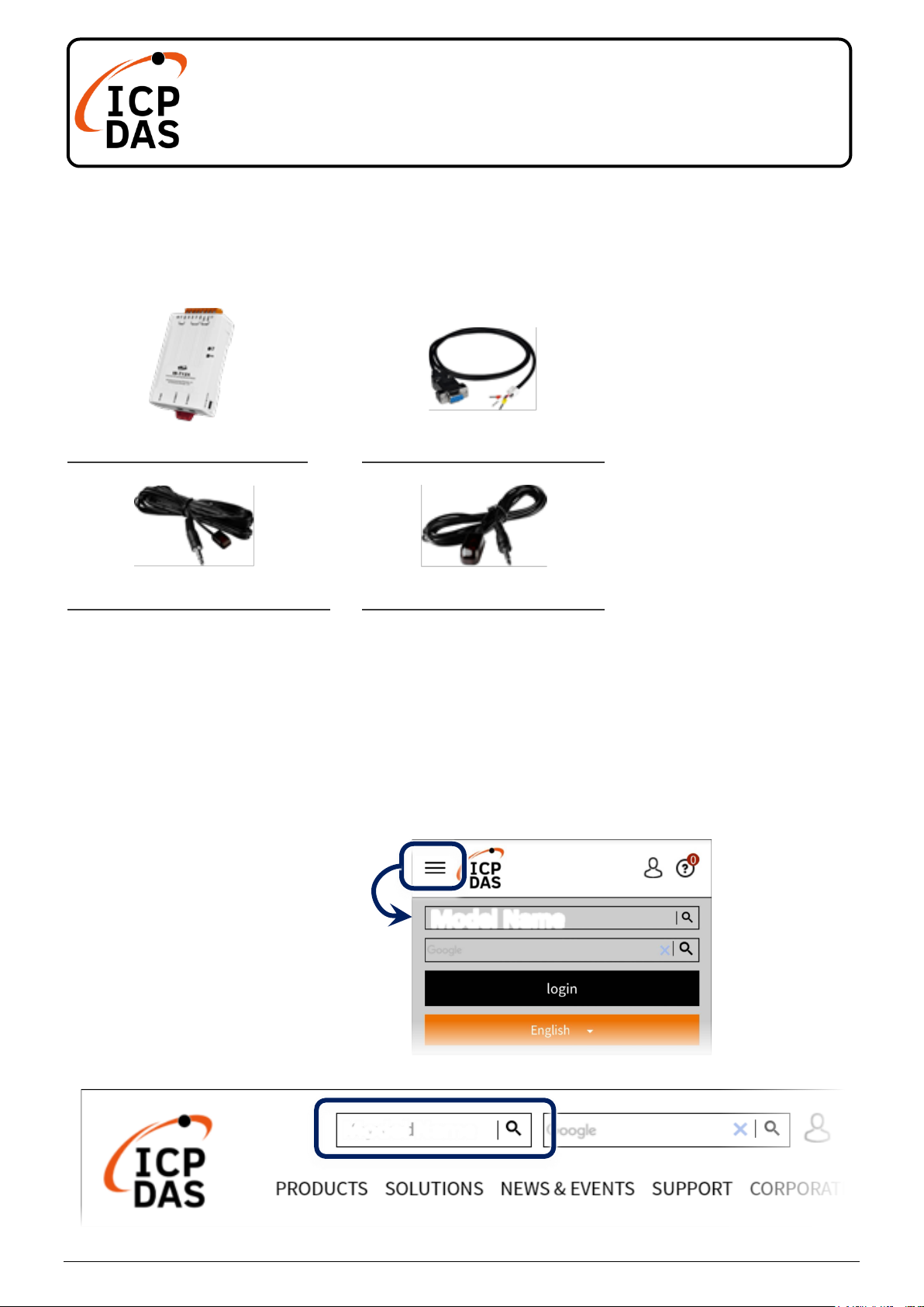
Packing List
In addition to this guide, the package includes the following items:
IR-712A
CA-0910 * 1
CA-IR-SH2251 * 2
CA-IR-SH2251-5 * 2
Technical Support
service@icpdas.com
www.icpdas.com
Resources
How to search for drivers, manuals and
spec information on ICP DAS website.
For Mobile Web
For Desktop Web
(IR-712A)
(IR-712A-5)
Model Name
Model Name
Page 2
P2
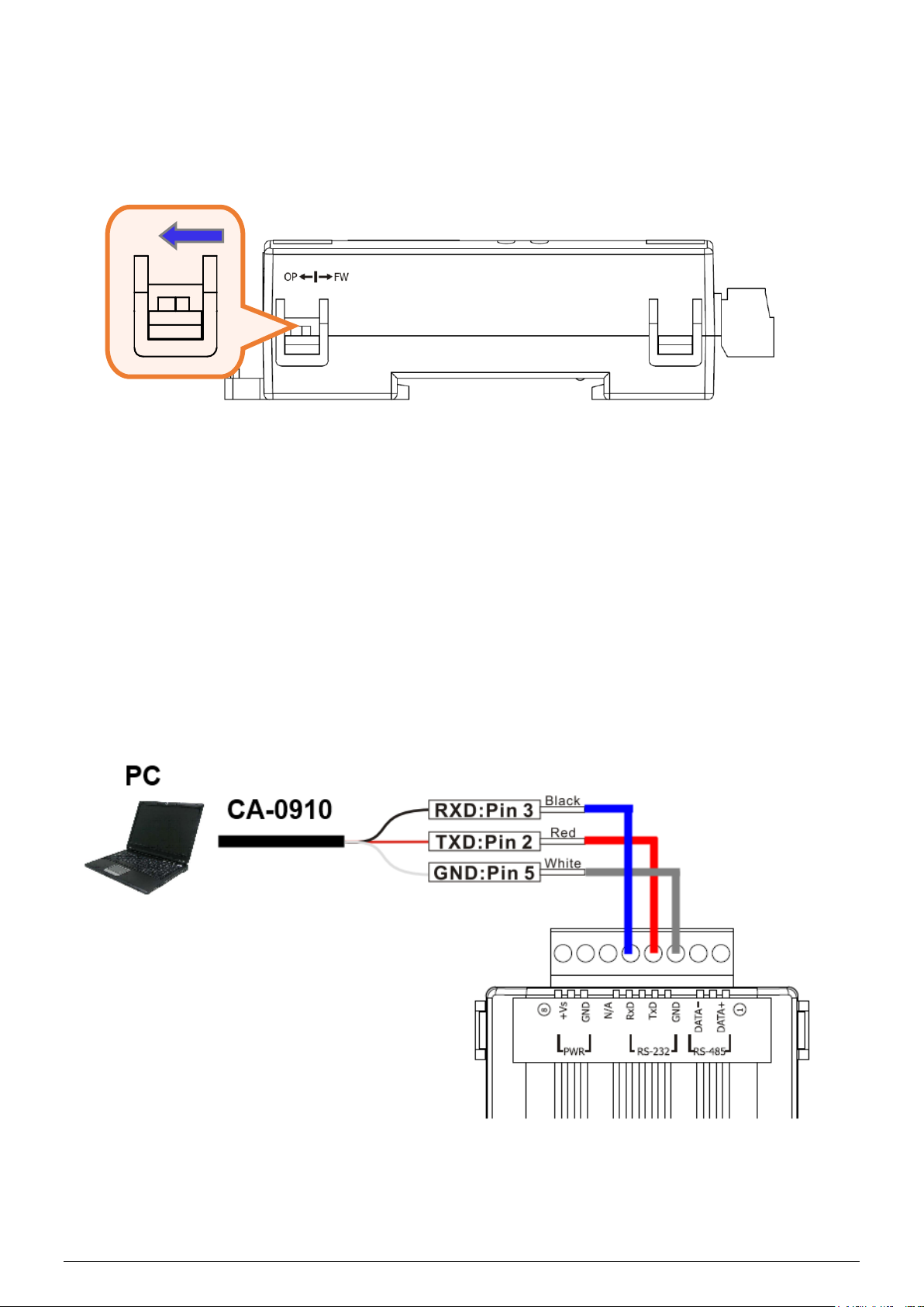
1. Check operation mode
Push DIP switch to the position of normal operation mode (OP).
2. Serial Wire Connection to PC
Use the RS-232 cable (CA-0910) to establish the wire connection between
IR-712A and PC as shown in the following figure. The DB9 (9-pin) connector of
CA-0910 is for PC COM port.
OP
Page 3
P3
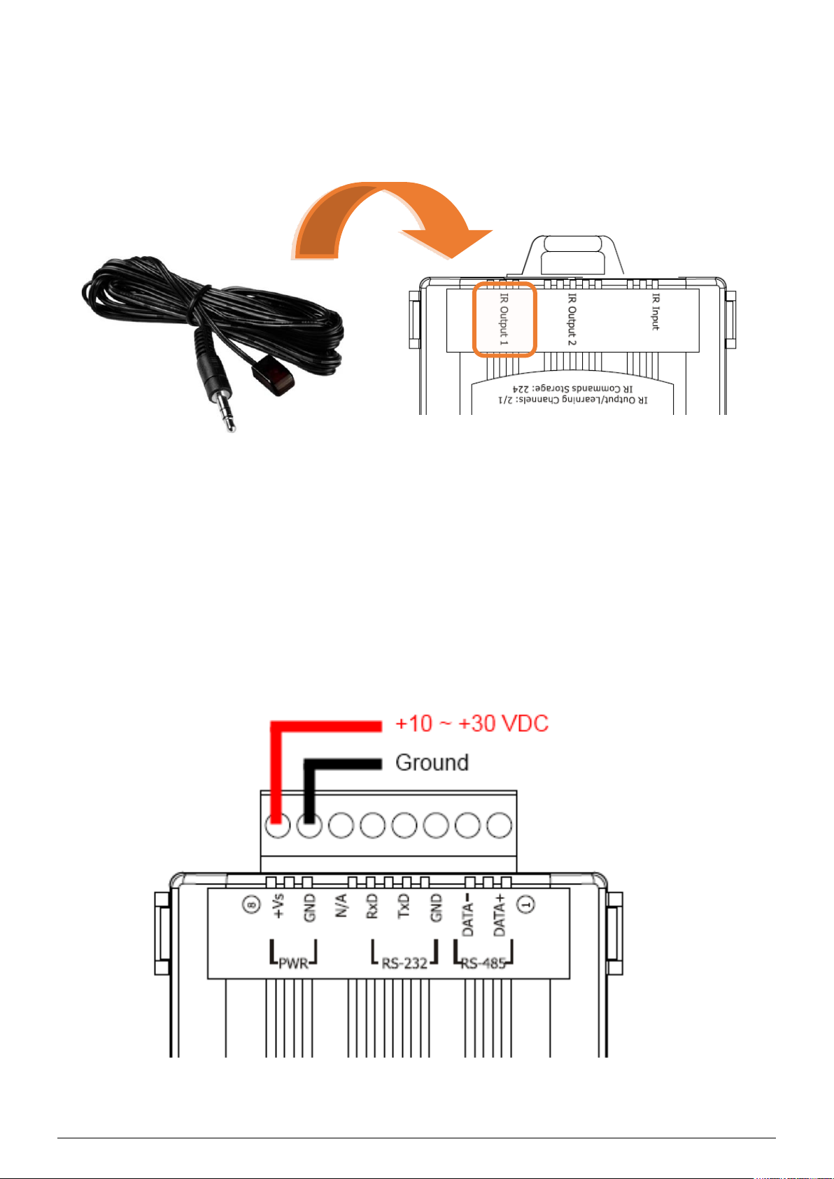
3. Plug in an IR Emitter Cable
Plug the IR emitter cable CA-IR-SH2251 into the 3.5 mm jack of the IR
Output 1.
4. Power Wire Connection
Connect the power supply cable (+10 ~ +30 VDC) to the power
connector.
Page 4

P4
5. Install IR Utility
Please get the IR Utility installation file (IR_Util_Setup_v#_#_#_#.zip)
from the web page of the product.
6. Serial Communication to the Module
Select “IR-712A” in the Module combobox. Select the default
communication settings: Baud rate = 115200 bps, Parity = None, Data
bits = 8, Stop bits = 1, and Modbus Net ID = 1. Then, click “Connect”
button to connect to the IR-712A and open the main window of the
IR-712 utility.
Page 5

P5
7. Set Device and IR Command Quantity
Please click the “Set Device & IR Command Quantity” button to open the
setup window. Three steps to bet set:
Step 1: Set device quantity.
(1) Set the Device Quantity to be 1.
(2) Press the “Set” button.
(3) Press the Next (right arrow) button.
3
2
1
Page 6

P6
Step 2: Configure the IR device names and its IR command
quantity.
(1) Enter Device Name and IR Command Quantity.
(2) Press the “Set” button.
(3) Press the Next (right arrow) button.
Step 3: Set each IR command name
The prefix number (e.g. 1_Play) is the number of an IR command stored
in the IR-712A. Click OK button to go back to main window of the
IR-712A utility.
1
2
3
3
4
2
1
Page 7

P7
8. Learn IR Commands
In the section “Test and Save Learned IR Commands” of the IR-712A
utility:
(1) Select the item in “Device Name” and “Command Name” combobox.
(2) Click “Learn On” button to enable IR learning mode (TR/LN LED is
ON).
(3) Aim the emitter head of the remote control (RC) to the “IR Input” hole
on IR-712A (distance less than 3 cm) and press the remote control
button which is to be learned in a short time. After IR learning is
finished, the TR/LN LED is OFF.
(4) Select IR Output 1 in the output channel combobox.
(5) Aim the IR emitter, which is plugged in IR Output 1 jack, to the IR
receiver of the controlled device. Click “Run Command” button to
check the effectiveness of the IR learning command. Repeat (2) and
(3) if no action on the device.
(6) Click “Save this Cmd” button.
(7) Repeat the above (1)~(6) to finish IR learning.
Besides, the color rectangle (marked a blue dotted frame) means:
➢ Red: Learning data is saved in the item of “Command Name”.
➢ Yellow: Get learning data form IR-712A. The data is buffered and lost
when selecting other item of “Command Name”.
➢ White: No learning data saved in the current item of “Command
Name”.
距離:
≤ 3 cm
遙控器
2
3
2
4
6
5
1
Page 8

P8
9. Download IR Commands to the Module
After IR learning finishes, click Menu [Download]-> [Download IR
Commands to IR-712A] to download the IR commands to the IR-712A.
10. Test IR Commands
Go to the “Test IR Commands in IR-712A” section:
(1) Select IR Command No.
(2) Select Output Channel to 1. Aim the IR emitter head to the appliance.
(3) Press “Transmit from IR-712A” button. The appliance reacts means
success.
1
3
2
 Loading...