

P1
IR-310-RM Quick Start
v1.4, Oct 2020
Packing List
In addition to this guide, the package includes the following items:
IR-310-RM
CA-0910
CA-IR-001
CA-IR-SH2251-5
Screw
Driver
Flat Head
Screws * 10
L108E
Rack Mount
Brackets * 2
Module
Connecting
Piece * 1
Wall Mount
Brackets * 2
Technical Support
service@icpdas.com
www.icpdas.com
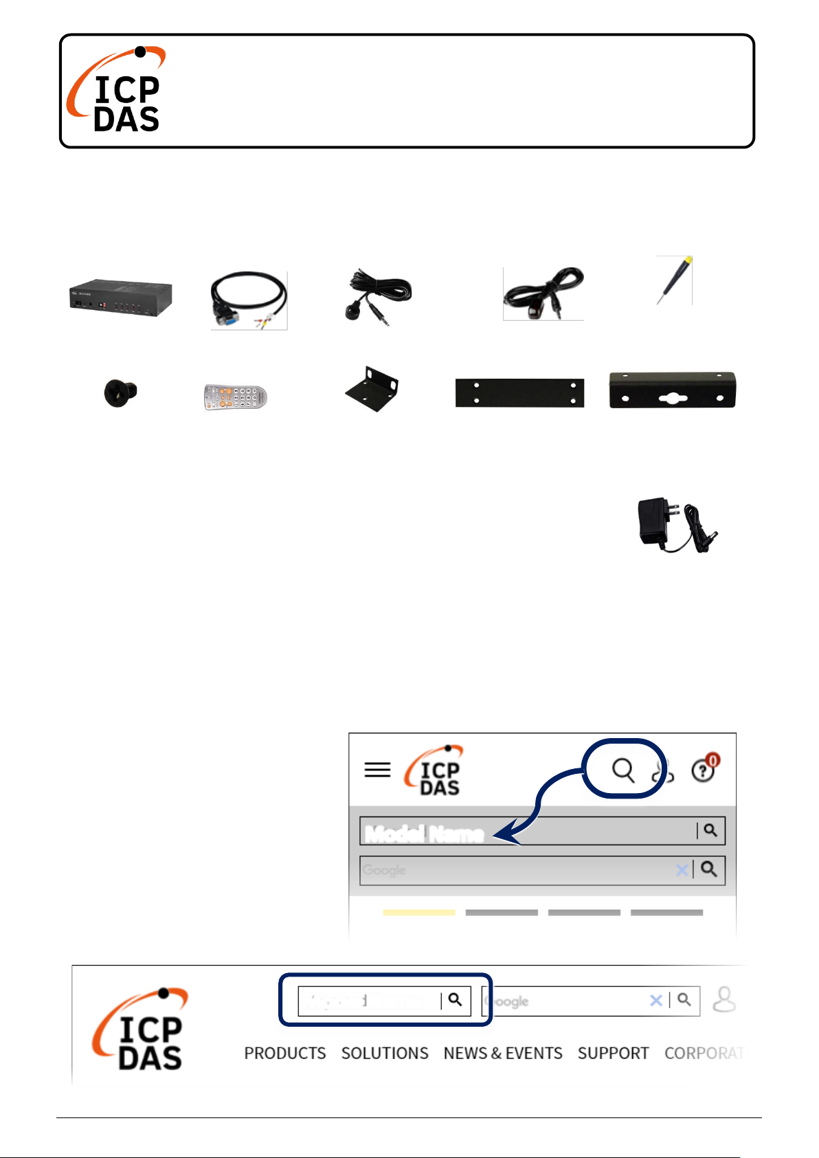
Resources
How to search for drivers, manuals and
spec information on ICP DAS website.
For Mobile Web
For Desktop Web
Model Name
Model Name
UP0061D-12PA58G
P2
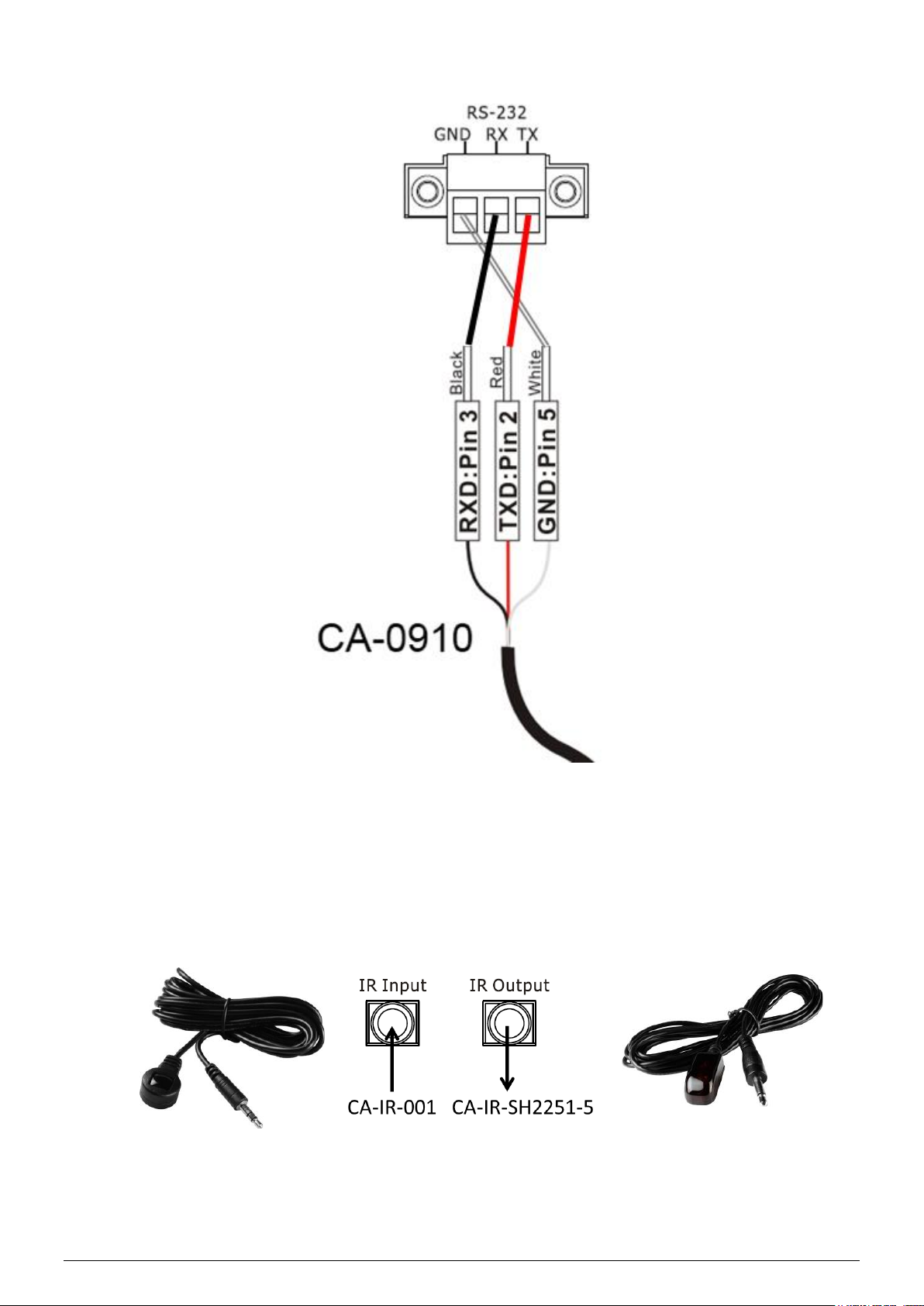
1. RS-232 Connection
2. Connection to the IR Interface
Please use the IR receiver cable CA-IR-001 for IR input jack and the IR
emitter cable CA-IR-SH2251-5 for IR output jack.
CA-IR-001
CA-IR-SH2251-5
P3
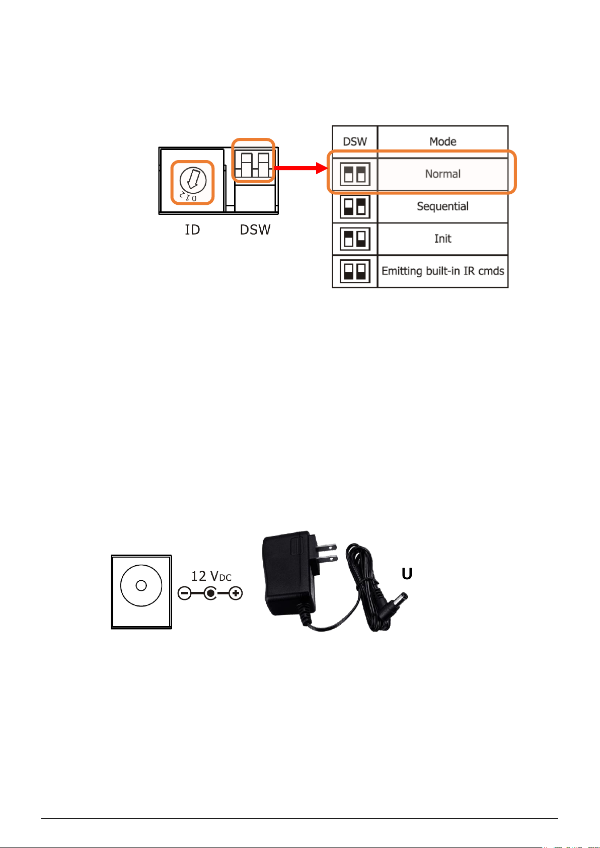
3. Rotary and DIP Switch
Make sure that the rotary switch is at ID = 1 and DIP switch is in Normal
mode for the subsequent manipulation.
4. Power Connection
IR-310-RM only supports +12 VDC. The power jack is at the rear of the
module. The accompanied UP0061D-12PA58G is the power supply for
IR-310-RM.
UP0061D-12PA58G

P4
5. Install IR Utility
Please get and install IR utility (IR_Util_Setup_Vx_x_x_x.zip) from the
Web page of the product.
6. Connect to the Module
Select “IR-310-RM” in the Module combobox. Select the default
communication settings: Baud rate = 9600 bps, Parity = None, Data bits
= 8, Stop bits = 1, and Modbus Net ID = 1. Then, click “Connect” button
to connect to the IR-310-RM and open the main window of the utility.

P5
7. View and test the relay outputs
Current states of 10 relays are indicated in the Relay Output section.
Relay states can be changed by clicking the circles.
8. Relay Control by the IR Remote
Please use an IR learning Remote (such as the accompanied L108E) to
learn the IR commands for IR-310-RM.
8.1 Test by L108E
By default, the IR learning remote L108E has stored 12 built-in IR
commands as shown in the following Table for the IR-310-RM with Net
ID = 1. Users can press these buttons to test IR remote function
immediately.
Click
L108E

P6
Table : Default buttons of the L108E
Btn
IR Cmd#
Btn
IR Cmd#
+
#192 (10 relays ON)
4
#198 (RL4 ON, others OFF)
-
#193 (10 relays OFF)
5
#199 (RL5 ON, others OFF)
0
#194 (RL0 ON, others OFF)
6
#200 (RL6 ON, others OFF)
1
#195 (RL1 ON, others OFF)
7
#201 (RL7 ON, others OFF)
2
#196 (RL2 ON, others OFF)
8
#202 (RL8 ON, others OFF)
3
#197 (RL3 ON, others OFF)
9
#203 (RL9 ON, others OFF)
Please refer to the Appendix A of the IR-310-RM User Manual for the
table of the built-in IR commands numbers.
8.2 Steps to learn IR commands
A. Download IR-relay-states to the IR-310-RM
(1) Launch IR-310-RM utility and go to the section of the “Relay States
Corresponding to IR Cmds”. IR-relay-state can be buffered in each
item (#=0~63) of the “IR Cmd No.” combobox by clicking the circles
representing the 10 relays (RL0 ~ RL9). Click a circle ON/OFF
means the relay ON(Normally open)/OFF(Normally closed).
(2) Set button: Download the current IR-Relay-State to the IR-310-RM.
Click

P7
B. Emit IR commands for IR learning remote
Plug the IR emitter cable (CA-IR-SH-2251-5) in the jack of IR output.
Aim the head of the IR emitter cable to the IR emitter of the learning
remote (L108E). Go to the “Emit IR Remote Commands” section. Click
the “Emit IR Command” to emit the IR command for the specified Net ID.
(Please refer to the manual of the L108E to learn the IR learning.)
C. Test by the IR Remote
Learning IR Commands
L108E

P8
9. Rack Mounting
The two rack mount brackets in the package are for rack mounting
environment.
The steel joint plate can join two IR-310-RMs to be of 19“ width for an
equipment rack.
10. Wall Mounting
The two wall mount brackets in the package are installed on the case as
follows
 Loading...