

Page 1

http://www.icpdas.com I8094A &I8094HGetting Started manualVer 1.3-- 1
i8094A & i-8094H Getting Started
(Version 1.3)
PAC WinCon-8000 Series Controllers
(Applied to: i8094A & i8094H)
Page 2

http://www.icpdas.com I8094A &I8094HGetting Started manualVer 1.3-- 2
Warranty
All products manufactured by ICPDAS Inc. are warranted against defective
materials for a period of one year from the date of delivery to the original
purchaser.
Warning
ICPDAS Inc. assumes no liability for damages consequent to the use of this
product. ICPDAS Inc. reserves the right to change this manual at any time
without notice. The information furnished by ICPDAS Inc. is believed to be
accurate and reliable. However, no responsibility is assumed by ICPDAS Inc. for
its use, or for any infringements of patents or other rights of third parties
resulting from its use.
Copyright
Copyright 1997-2009 by ICPDAS Inc., LTD. All rights reserved worldwide.
Trademark
The names used for identification only maybe registered trademarks of
their respective companies.
License
The user can use, modify and backup this software on a single machine.
The user may not reproduce, transfer or distribute this software, or any copy, in
whole or in part.
Page 3

http://www.icpdas.com I8094A &I8094HGetting Started manualVer 1.3-- 3
CONTENTS
1 INTRODUCTION OF I8094A/I8094H MOTION
CONTROL MODULE...........................................................7
1.1 i8094A/i8094H Introduction.....................................................................7
1.2 Hardware Specification.......................................... 8
1.2.1 Main Specification............................................ 8
1.2.2 Interpolation Function........................................ 8
1.2.3 Pulse Output.................................................. 8
1.2.4 Encoder Input................................................. 9
1.2.5 Position counter.............................................. 9
1.2.6 Auto-Homing................................................... 9
1.2.7 Servo Motor Input Signal ..................................... 10
1.2.8 Limit Switch Input Signal .................................... 10
1.2.9 Other Input Signals.......................................... 10
1.2.10 Emergency Stop Signal Input ................................. 10
1.2.11 General Output Signal....................................... 10
1.2.12 Integral Input Signal Filters ............................... 10
1.2.13 Software Limit.............................................. 10
1.2.14 Manual Pulse Generator ...................................... 11
1.2.15 Module status LED Indicators ................................ 11
1.2.16 Compare Trigger Output ...................................... 11
1.2.16 FRnet (i8094F only)......................................... 11
1.3 Environment.............................................................................................12
1.4 Ordering Information..............................................................................12
2 HARDWARE INSTALLATION......................................13
2.1 i8094A/i8094H Check Package & Installation......................................13
2.1.1 Check Package................................................ 13
2.1.2 i8094A/i8094H Installation ................................... 13
2.2 DN-8468GB Terminal Board..................................................................15
2.2.1 DN-8468GB Board Layout....................................... 15
2.2.2 Pin Assignment............................................... 16
2.2.3 Jumper and Switch Settings ................................... 22
2.3 Input/Output Connections......................................................................24
2.3.1 Pulse output signals......................................... 24
Page 4

http://www.icpdas.com I8094A &I8094HGetting Started manualVer 1.3-- 4
2.3.2 Connection for Limit switch Signal ........................... 26
2.3.3 General Purpose DI Signals(nINPOS,nALARM) .................... 27
2.3.4 Encoder Signals.............................................. 28
2.3.5 External pulse signal........................................ 29
2.3.6 Emergency Stop Signal........................................ 30
2.3.7 External Pulse Input Signal (EXP+,EXP-) ...................... 31
2.3.8 Servo On/Off Output Signal (ENABLE) .......................... 32
2.3.9 Compare Trigger Output....................................... 32
2.4 Connection Example for Motor Driver .................................................33
3 I8094A/I8094H SOFTWARE DEVELOPMENT...........34
3.1 Software development Overview............................................................34
3.1.1 Register Module.............................................. 35
3.2 Safety IO Setting (Troubleshooting for Motion not working).............35
3.2.2 Configure the Servo ALARM Signals ............................ 35
3.2.3 Configure the Limit Switch Signals(±EL) ...................... 36
3.2.4 Configure the Software Limit(±SEL) ........................... 36
3.3 Error Checking(GET_ERROR).............................................................36
3.5 Manual Pulse Generator Testing (Optional).........................................38
3.6 Home Search.............................................................................................40
3.6.1 Home Search Configuration .................................... 40
3.6.2 Running the Home Search ...................................... 41
3.7 Basic Motion.............................................................................................42
3.7.1 Speed Profile of the Motion Control .......................... 42
3.7.2 Basic Settings For Single Axis ............................... 44
3.7.3 Basic Motion of Single Axis .................................. 45
3.7.4 Basic Setting of Muti-Axes Interpolation ..................... 46
3.7.5 Basic Motion of Muti-Axes Interpolation ...................... 47
3.8 Advance Motion .......................................................................................48
3.9 Motion Synchronization Action..............................................................49
4 SOFTWARE GETTING STARTED GUIDE.................50
4.1 WinCon eVC++........................................................................................50
4.1 WinCon eVC++ Guideline ......................................................................50
4.1.1 Files you will need.......................................... 50
4.1.2 Create a new eVC++ Application Project ....................... 50
4.1.3 Add the Reference Path into eVC++ Application Project ........52
4.1.4 Start the eVC++ Sample....................................... 53
Page 5

http://www.icpdas.com I8094A &I8094HGetting Started manualVer 1.3-- 5
4.2 WinCon Microsoft Visual Studio .NET 2003(VB.NET,C#)..............55
4.3 I-8000 Turbo C++.....................................................................................55
5 MPTOOL : EZMAKE......................................................56
5.1 Start EzMake............................................................................................56
5.2 Specify the I-8094H to be used ...............................................................56
5.3 Operation Page.........................................................................................57
5.3.1 Tree Diagram................................................. 57
5.3.2 Main Menu.................................................... 58
5.3.3 Function & Parameter Editor .................................. 61
5.3.4 Function Library Groups Menu ................................. 62
5.3.5 Function Display Menu........................................ 62
5.3.6 Message & Status............................................. 63
5.4 Download files and programs execution................................................65
5.4.1 Download the file............................................ 65
5.4.2 Program execution............................................ 65
APPENDIX A .......................................................................66
A.1 Setup the Development Environment of I8094A/I8094H....................66
A.1.1 eVC ++ 4.0................................................... 66
A.2 Appearance and Dimension ...................................................................67
APPENDIX B DN-8468 SERIES DAUGHTER BOARD.68
B.1 DN-8468M Daughter Board...................................................................68
B.1.1 Board Layout for DN-8468M .................................... 68
B.1.2 Signal Connections for DN-8468M .............................. 70
B.1.3 Jumper and Switch Settings ................................... 76
B.2 DN-8468P Daughter Board.....................................................................78
B.2.1 Board Layout for DN-8468P .................................... 78
B.2.2 Signal Connections for DN-8468P .............................. 79
B.2.3 Jumper and Switch Settings ................................... 84
B.3 DN-8486Y Daughter Board....................................................................86
B.3.1 Board Layout for DN-8468Y .................................... 86
B.3.2 Signal Connections for DN-8468Y .............................. 87
B.3.3 Jumper and Switch Settings ................................... 92
B.4 DN-8468D Daughter Board....................................................................94
B.4.1 Board Layout for DN-8468D .................................... 94
Page 6

http://www.icpdas.com I8094A &I8094HGetting Started manualVer 1.3-- 6
B.4.2 Signal Connections for DN-8468D .............................. 95
B.4.3 Jumper and Switch Settings .................................. 103
B.5 DN-8468FB Daughter Board................................................................106
B.5.1 Board Layout for DN-8468FB .................................. 106
B.5.2 Signal Connections for DN-8468FB ............................ 107
B.5.3 Jumper and Switch Settings .................................. 115
Page 7

http://www.icpdas.com I8094A &I8094HGetting Started manualVer 1.3-- 7
1 Introduction of i8094A/i8094H Motion Control Module
1.1 i8094A/i8094H Introduction
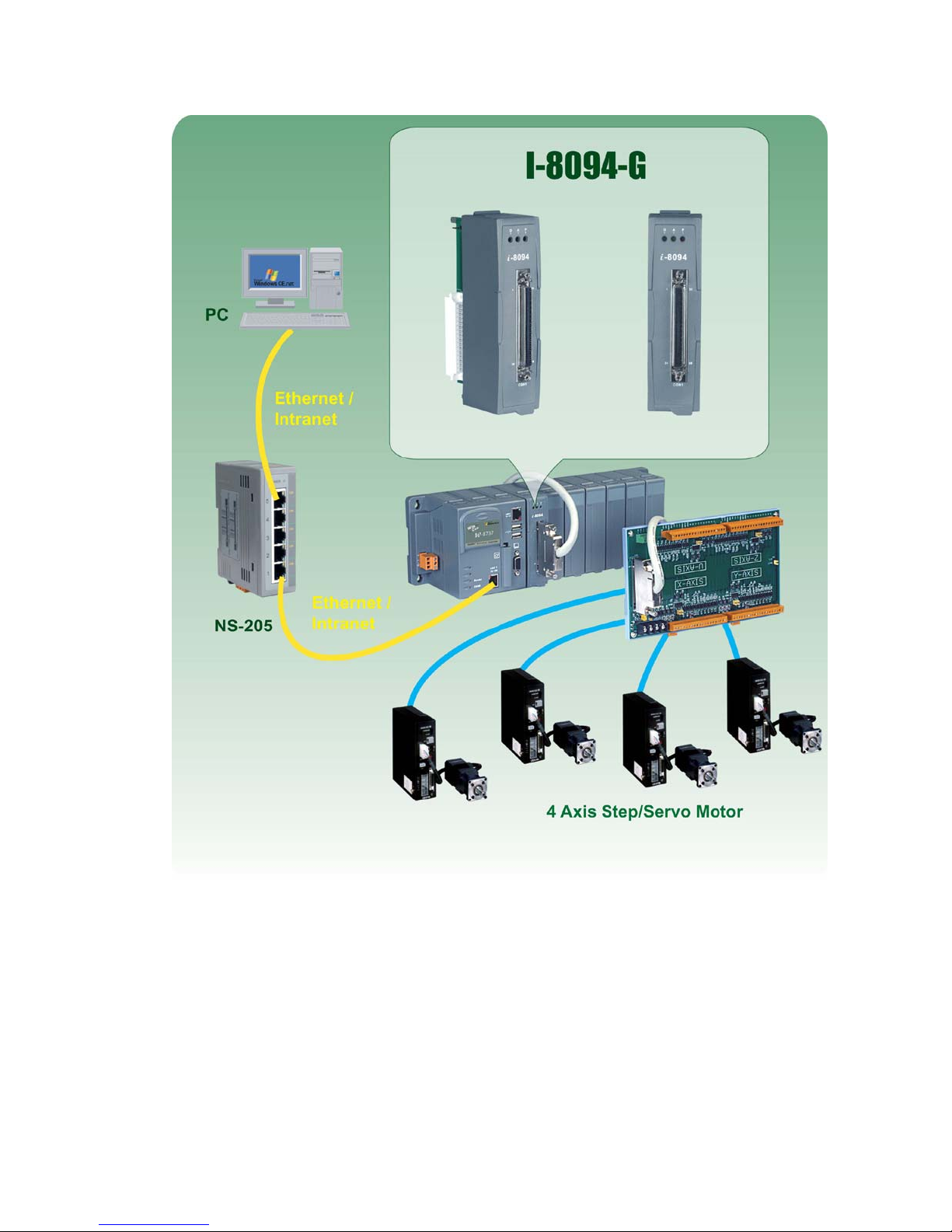
i8094A/i8094H is a motor motion control module with built-in CPU, DPRAM, FRAM
and SRAM; it is integrated axis control module that support 4-axis stepper/servo motor
motion control; the maximum output Pluse could reach 4M PPS, this module could be applied
to ICP DAS WinCon-8000 controllers. I8094A/i8094H motor motion control module is good
for motion control applications for general purposes; it provides a lot of motion control
features that offers customers easy-to-use and intuitive solutions. These features include:
2/32~3-axes linear interpolation, 2-axes circular interpolation, T/S-curve acceleration/
deceleration, various synchronous actions, automatic homing, and many others.
In addition, i8094H equips with built-in ICP DAS’s unique FRnet distributed DI/DO
control functions, it could connect externally to 128 DI and 128 DO control points; each with
cycle time of 0.74ms. Moreover, when i8094A/i8094H performs functions above, it does not
consume WinCon system resources. The CPU could monitor other status at the same time. It
require very little system resources, therefore one WinCon-8000 could insert with a couple of
i8094A/i8094H modules, to perform control of multi-axis (4,8 ....) motion Control on the
same controller.
Besides, this module has a few built-in hardware like CPU, etc, therefore supports a
series of macro programming functions. It provides customers multiple sets of macro
programming functions, hence will reduce programming effort and enable programmers to
develop programs more flexibly. ICP DAS also provides a wide range of demo programs and
macro programming functions sets to eliminate programming tasks; making it a highly
cost-effective motion control system designed platform.
Page 8

http://www.icpdas.com I8094A &I8094HGetting Started manualVer 1.3-- 8
1.2 Hardware Specification
1.2.1 Main Specification
ASIC Chip MCX314As
CPU 80186
FRAM 128KB
SRAM 512KB
EEPROM 512KB
Number of controllable 4-Axes, Pulse output (stepping &
servo motor)
Up to 4M PPS pulse output 4 M PPS
1.2.2 Interpolation Function
2-axes & 3-axes linear interpolation
Interpolation range −2,147,483,646 ~ +2,147,483,646
Vectors speed of interpolation 1 PPS ~ 4M PPS
Precision of interpolation ± 0.5 LSB
Circular interpolation
Interpolation range −2,147,483,646 ~ +2,147,483,646
Vectors Speed of interpolation 1 PPS ~ 4M PPS
Relative interpolation function
Any 2-axes or 3-axes interpolation
Fixed vectors speed
Continuous interpolation
1.2.3 Pulse Output
Output speed range 1 PPS ~ 4 MPPS
Output precision ± 0.1%
Jerk range of S-curve 954 ~ 62.5 x 10^6 PPS/S^2
477 x 10^3 ~ 31.25 x 10^9 PPS/S^2
Acceleration/deceleration range 125 ~ 1 x 10^6 PPS/S
62.5×10^3 ~ 500 x 10^6 PPS/S
Speed precision 1 PPS ~ 500PPS( Depends on the
max. speed)
Page 9

http://www.icpdas.com I8094A &I8094HGetting Started manualVer 1.3-- 9
Output numbers 0 ~ 4,294,967,295 / unlimited
Velocity profiles mode:
Fixed
Symmetrical & Asymmetrical Trapezoidal velocity profile
Symmetrical & Asymmetrical S-curve velocity profile
Acceleration & Deceleration mode
Auto
By user define
Position & Speed change on the fly
Fixed pulse output by Trapezoidal and S-curve velocity profile
Pulse output option: CW/CCW, PULSE/DIR
Programmable logic level (Rising Edge/ Falling Edge)
1.2.4 Encoder Input
Encoder option: A/B phase, Up/Down
Programmable A/B phase mode: 1, 1/2, and 1/4 A/B phase
1.2.5 Position counter
Command counter range −2,147,483,648 ~ +2,147,483,647
Encoder counter range −2,147,483,648 ~ +2,147,483,647
Programmable ring counter
Programmable direction of counter
Using DI(IN3) to Clear feedback counter
Programmable read & write counter
1.2.6 Auto-Homing
Four Steps
Step 1 ( High-speed ”Near Home” searching)
Step 2 ( Low-speed ”Home” searching)
Step 3 ( Low-speed Index Z searching)
Step 4 ( High-speed offset drive)
By software functions, each step enables user to configure actions and
directions, therefore, offers user more than 10 homing modes to choose from.
Page 10

http://www.icpdas.com I8094A &I8094HGetting Started manualVer 1.3-- 10
1.2.7 Servo Motor Input Signal
Alarm
IN2 options: In Position or Servo Ready signal
Input signal options: Enable/Disable and logical level.
1.2.8 Limit Switch Input Signal
Two-limit switch signal for each axis: +Limit, −Limit
Programmable logic level
Programmable action mode( slow-down stop or immediately stop)
1.2.9 Other Input Signals
IN3 : could be used for other applications; for example: as a trigger of
synchronal control, etc.
1.2.10 Emergency Stop Signal Input
There is an Emergency stop signal for Each module.
1.2.11 General Output Signal
The Servo-on signal (nOUT1) can be used as servo-on control or general
purpose output signal for each axis.
1.2.12 Integral Input Signal Filters
The motion module is equipped with an integral type filter in the input step of
each input signal. User can be selected a filter time constant.
1.2.13 Software Limit
There are two software-limit for each axis: -SLimit & + SLimit ( Setting range :
−2,147,483,646 ~ +2,147,483,646)
Page 11

http://www.icpdas.com I8094A &I8094HGetting Started manualVer 1.3-- 11
1.2.14 Manual Pulse Generator
Fixed Pulse Driving Mode (CW/CCW pulse mode)
Continuous Pulse Driving Mode (CW/CCW pulse mode)
Manual pulsar mode(A/B phase pulse mode)
1.2.15 Module status LED Indicators
Red LED Æ Power Indicator (will turn on when power is on)
Orange LED Æ Servo Alarm Indicator
Ex: Misuibishi driver, No Alm: Orange LED will turn on.
Green LED Æ Running Motion Indicator ( will turn on when under Running
Motion)
1.2.16 Compare Trigger Output
For X-axis and Y-axis only
Output mode: 5V TTL
1.2.16 FRnet (i8094F only)
DI Æ up to 128 connecting points
DO Æ up to 128 connecting points
Page 12

http://www.icpdas.com I8094A &I8094HGetting Started manualVer 1.3-- 12
1.3 Environment
Operating Temp: -20 ~ + 75°C
Storage Temp: -30 ~ +85°C
Operating Humidity: 10 ~ 85%,non-condensing
Storage Humidity: 5 ~ 90%,non-condensing
I/O optically isolated 2500Vrms
External Power supply( Input): 24V DC (connect to terminal board)
1.4 Ordering Information
W-8x31-GM1 PAC controllers
i8094A/i8094H 4-axes motion control module
DN-8468GB i8094A/i8094H interface board
DN-8468DB i8094A/i8094H interface board
DN-8468MB i8094A/i8094H interface board
DN-8468PB i8094A/i8094H interface board
DN-8468YB i8094A/i8094H interface board
CA-SCSI15 68-pin SCSI-II cable, length: 1.5 m
CA-SCSI30 68-pin SCSI-II cable, length:3 m
CA-SCSI50 68-pin SCSI-II cable, length:5 m
Page 13

http://www.icpdas.com I8094A &I8094HGetting Started manualVer 1.3-- 13
2 HARDWARE INSTALLATION
2.1 i8094A/i8094H Check Package & Installation
2.1.1 Check Package
i8094A/i8094H is a 4-axes stepping/servo motor control module; you will need
a WinCON-8000 series PAC to serve as the controller.
You will need:
W-8x31-GM1 PAC controller
You will also need the following items to implement installation of i8094A/i8094H
modules:
i8094A/i8094H 4-axes motion control module
DN-8468 series i8094A/i8094H interface board
CA-SCSI15 68-pin SCSI-II cable, length: 1.5 m
2.1.2 i8094A/i8094H Installation
Before Installation
1. You will need a ICP DAS (W-8000series) PAC controller with I/O expansion slot
(currently we offer a variety of 3- or 7- slot)
2. Turn off the power.
Modules Installation & Wiring
1. Position the i8094/i8094F module over the I/O Expansion Slot, aligning the
module card with the groove at the side of the Expansion Slot.
2. Insert the module into the I/O Expansion Slot, glide the module card along the
groove; press down the module until it is completely seated on the Expansion
Slot.
3. Secure the module by push down the “LOCK” latch.
4. Connect the i8094/i8094F with DN-8468G by a CA-SCSI15 cable, as the below
figure:
Page 14
http://www.icpdas.com I8094A &I8094HGetting Started manualVer 1.3-- 14
[此圖要修正為I-8094A/H]
Page 15
http://www.icpdas.com I8094A &I8094HGetting Started manualVer 1.3-- 15
2.2 DN-8468GB Terminal Board
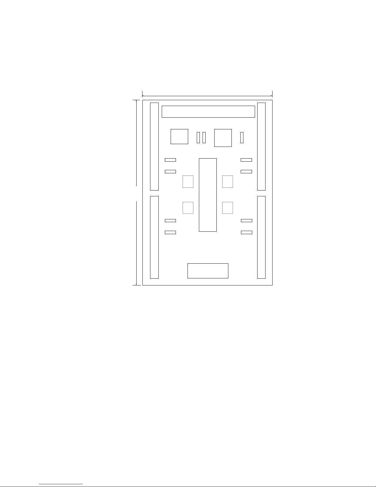
2.2.1 DN-8468GB Board Layout
CON6
RJ1
CON2CON4
CON3CON5
CON1
68 PIN SCSI
EMG
SW
TB2
JP7
JP5 JP6
X Y
Z U
DN-8468G
107mm
162mm
JP8
JP9
JP13
JP12
JP11
JP10
JP15
JP14
Fig. 2.0 DN-8468G Board layout
Page 16
http://www.icpdas.com I8094A &I8094HGetting Started manualVer 1.3-- 16
2.2.2 Pin Assignment
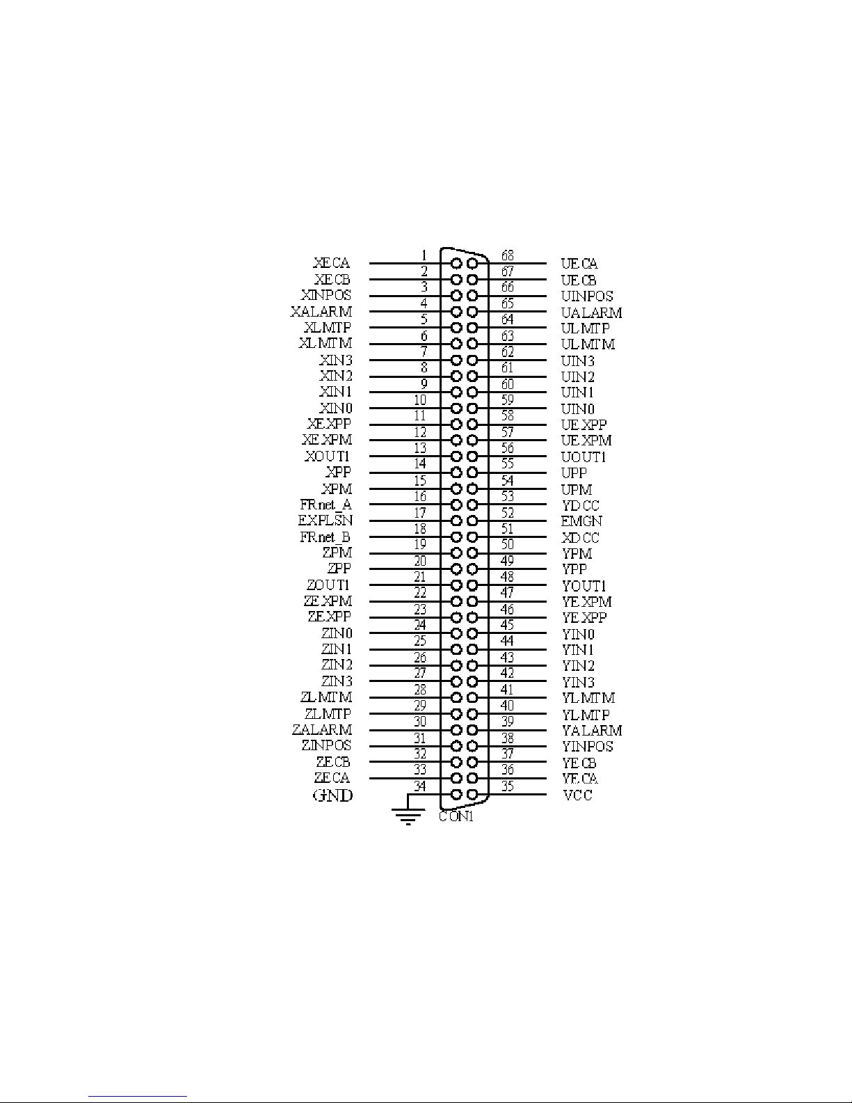
CON1
68-pin SCSI II Pin Assignment (connector to connect modules and wiring terminal board)
Fig. 2.1 CON1 I/O connector pin assignment
Page 17

http://www.icpdas.com I8094A &I8094HGetting Started manualVer 1.3-- 17
Table 2.1 DN-8468G I/O connector signal description (part 1)
Pin name Pin number Description
XECA 1 Encoder A-phase signal for X axis
YECA 36 Encoder A-phase signal for Y axis
ZECA 33 Encoder A-phase signal for Z axis
UECA 68 Encoder A-phase signal for U axis
XECB 2 Encoder B-Phase signal for X axis
YECB 37 Encoder B-Phase signal for Y axis
ZECB 32 Encoder B-Phase signal for Z axis
UECB 67 Encoder B-Phase signal for U axis
XINPOS 3 In-position signal for X axis
YINPOS 38 In-position signal for Y axis
ZINPOS 31 In-position signal for Z axis
UINPOS 66 In-position signal for U axis
XALARM 4 Alarm signal for X axis
YALARM 39 Alarm signal for Y axis
ZALARM 30 Alarm signal for Z axis
UALARM 65 Alarm signal for U axis
XLMTP 5 Limit switch input signal (+) for X axis
YLMTP 40 Limit switch input signal (+) for Y axis
ZLMTP 29 Limit switch input signal (+) for Z axis
ULMTP 64 Limit switch input signal (+) for U axis
XLMTM 6 Limit switch input signal (-) for X axis
YLMTM 41 Limit switch input signal (-) for Y axis
ZLMTM 28 Limit switch input signal (-) for Z axis
ULMTM 63 Limit switch input signal (-) for U axis
XIN3 7 Input 3 signal for X axis
YIN3 42 Input 3 signal for Y axis
ZIN3 27 Input 3 signal for Z axis
UIN3 62 Input 3 signal for U axis
XIN2 8 Input 2 signal for X axis
XIN2 43 Input 2 signal for Y axis
XIN2 26 Input 2 signal for Z axis
XIN2 61 Input 2 signal for U axis
XIN1 9 Input 1 signal for X axis
YIN1 44 Input 1 signal for Y axis
ZIN1 25 Input 1 signal for Z axis
UIN1 60 Input 1 signal for U axis
XIN0 10 Input 0 signal for X axis
YIN0 45 Input 0 signal for Y axis
ZIN0 24 Input 0 signal for Z axis
UIN0 59 Input 0 signal for U axis
Page 18

http://www.icpdas.com I8094A &I8094HGetting Started manualVer 1.3-- 18
Table 2.2 DN-8468G I/O connector signal description (part 2)
Pin name Pin number Description
XEXPP 11 EXT pulsar input signal (+) for X axis
YEXPP 46 EXT pulsar input signal (+) for Y axis
ZEXPP 23 EXT pulsar input signal (+) for Z axis
UEXPP 58 EXT pulsar input signal (+) for U axis
XEXPM 12 EXT pulsar input signal (-) for X axis
YEXPM 47 EXT pulsar input signal (-) for Y axis
ZEXPM 22 EXT pulsar input signal (-) for Z axis
UEXPM 57 EXT pulsar input signal (-) for U axis
XDRIVE 13 Driver enable signal for X axis
YDRIVE 48 Driver enable signal for Y axis
ZDRIVE 21 Driver enable signal for Z axis
UDRIVE 56 Driver enable signal for U axis
XPP 14 Driving pulsar signal (+) for X axis
YPP 49 Driving pulsar signal (+) for Y axis
ZPP 20 Driving pulsar signal (+) for Z axis
UPP 55 Driving pulsar signal (+) for U axis
XPM 15 Driving pulsar signal (+) for X axis
YPM 50 Driving pulsar signal (+) for Y axis
ZPM 19 Driving pulsar signal (+) for Z axis
UPM 54 Driving pulsar signal (+) for U axis
XOUT1 16 Output 1 signal for X axis
YOUT1 48 Output 1 signal for Y axis
ZOUT1 21 Output 1 signal for Z axis
UOUT1 56 Output 1 signal for U axis
EXPLSN1 17 EXT pulse input signal for interpolation
EMGN1 52 Emergency stop input signal
FrnetA 16 FRnet port A
FrnetB 18 FRnet port B
XDCC 51 Deviation Counter Clear for X axis
YDCC 53 Deviation Counter Clear for Y axis
GND 34 Ground
VCC 35 External power (12~24V)
Page 19
http://www.icpdas.com I8094A &I8094HGetting Started manualVer 1.3-- 19
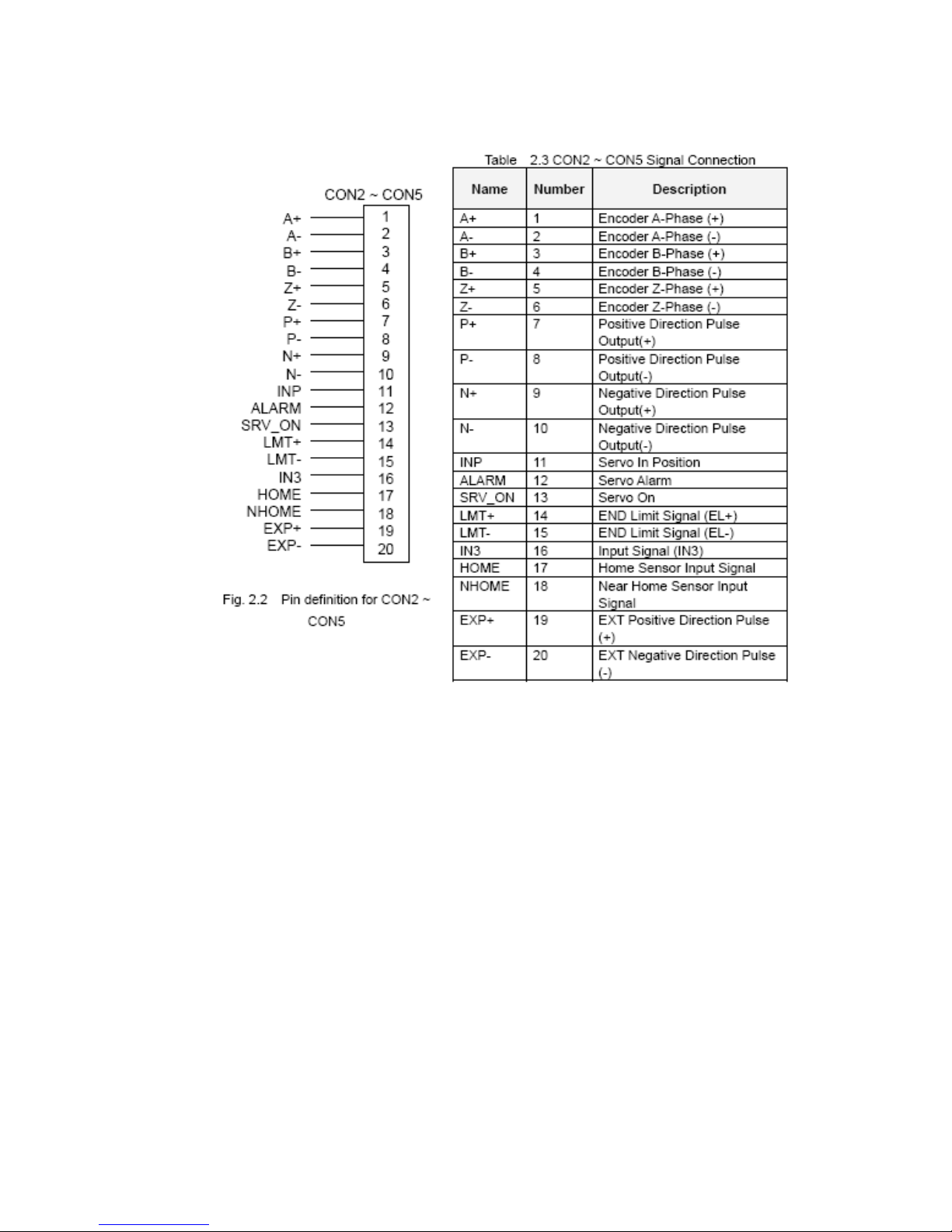
CON2 ~ CON5 (AXIS X、Y、Z、U I/O connector Wiring information)
Page 20
http://www.icpdas.com I8094A &I8094HGetting Started manualVer 1.3-- 20
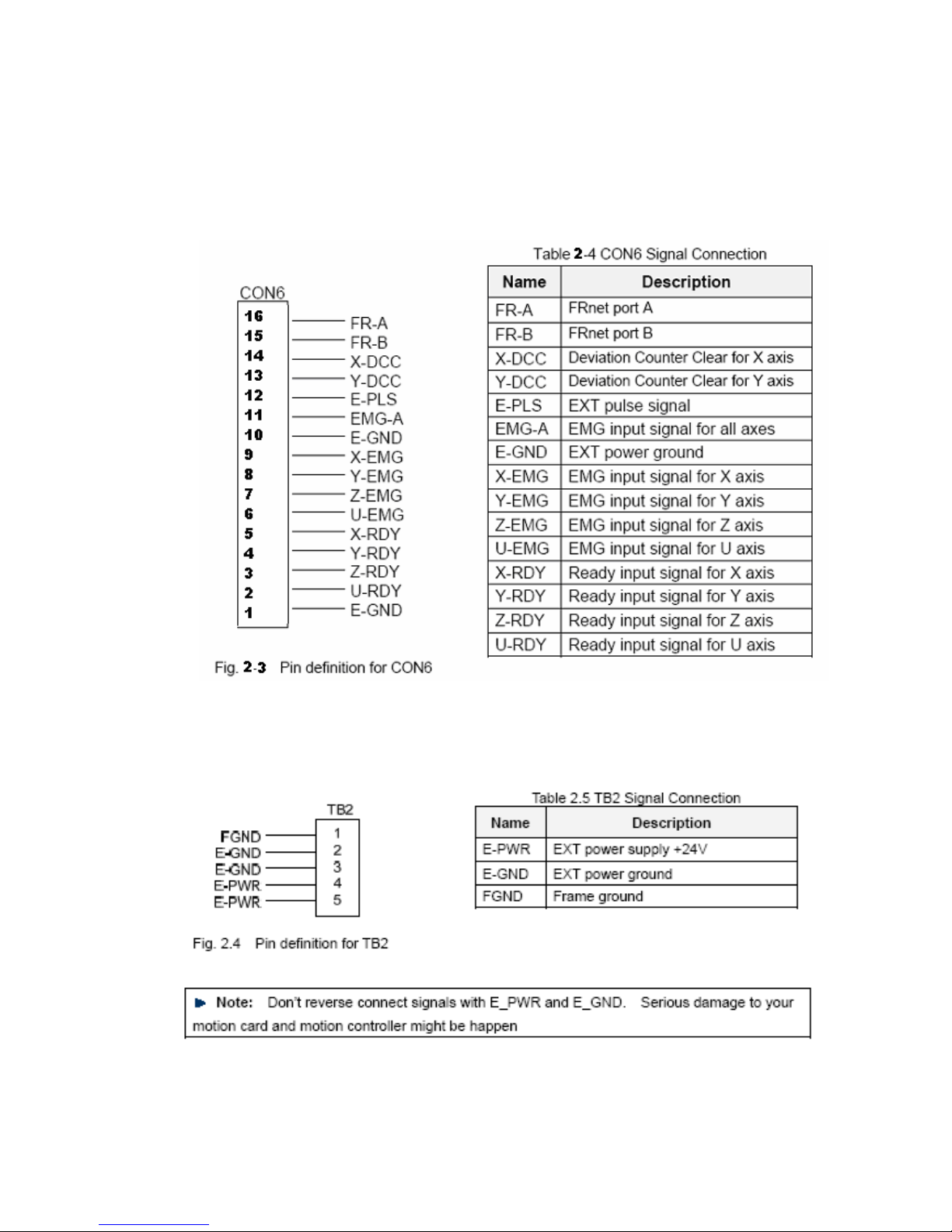
The connector CON6 is 16-pin connector for you to connect to the RDY & EMG signals,
external Pulse input, and FRnet connectors (i8094H only) of the motor drivers, enables to
connect with external DI/DO modules, etc.. FRnet(i8094HF)connectors could connect to
FRnet series IO modules, such as FR-2053, FR-2057, etc. For more information, please go
to website: http://www.icp das.com/products/Remote_IO/frnet/frnet_introduction.htm
TB2: External power supply input connector
Page 21
http://www.icpdas.com I8094A &I8094HGetting Started manualVer 1.3-- 21
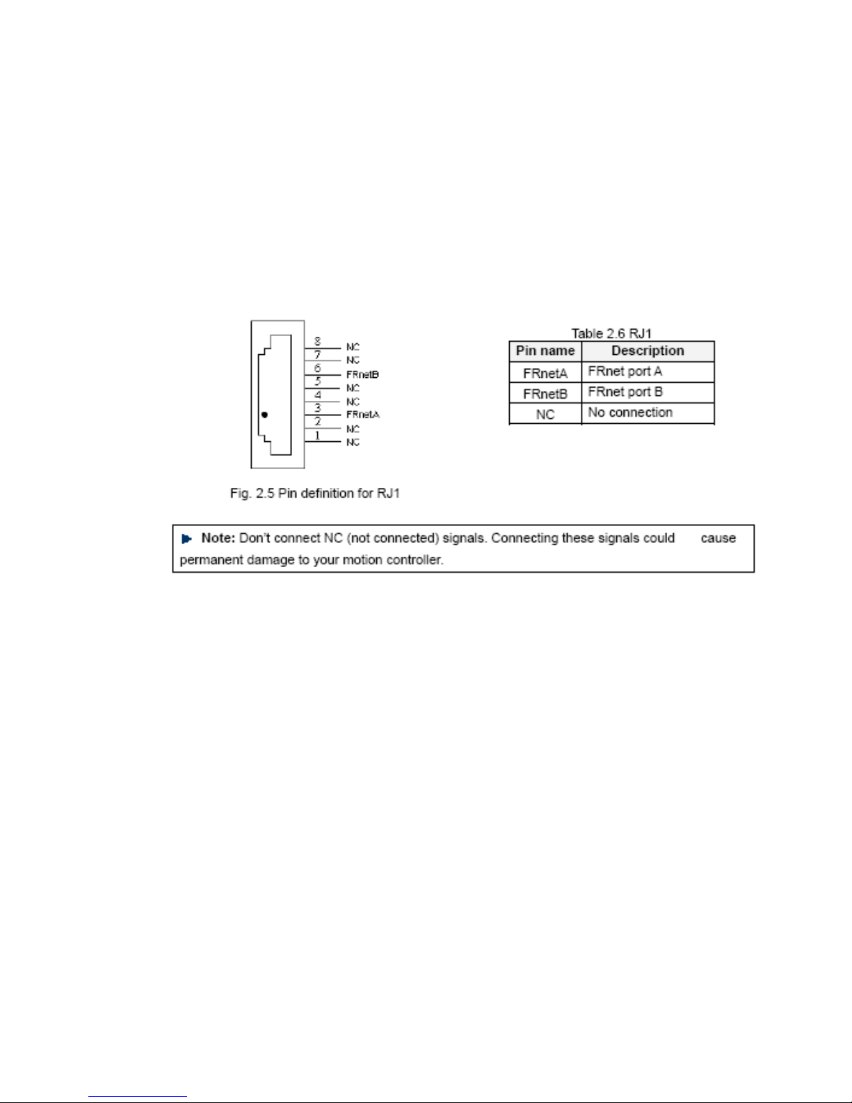
RJ1 ( I/O signals of the FRnet):
It is connector connect to FRnet – an 8-pin RJ45 connector. FRnet (i8094HF) connector could
connect to FRnet series IO modules such as FR-2053, FR-2057. For more information, please
refer to ICP DAS website:
http://www.icpdas.com/products/Remote_IO/frnet/frnet_introduction.htm
Fig.2.5 Pin assignment for the 8-pin connector on the DN-8468G.
Table 2.6 I/O connector signal description.
Page 22
http://www.icpdas.com I8094A &I8094HGetting Started manualVer 1.3-- 22
2.2.3 Jumper and Switch Settings
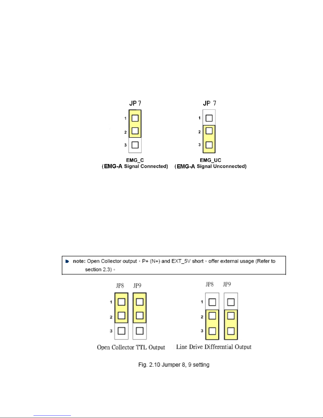
JP 7 provides control over the EMG-A signal of the CON6 connector. The
following diagram shows the jumper positions and its corresponding
states.
Fig. 2.6 Jumper 7 setting
JP8/9, JP10/1 1, JP12/13, JP14/15: Jumper 8~15 are used to set the signal type of
the pulse output signals. The output signal type could be differential line driver
output (2-3 Pin short )or open collector output(1-2 Pin short).
Page 23
http://www.icpdas.com I8094A &I8094HGetting Started manualVer 1.3-- 23
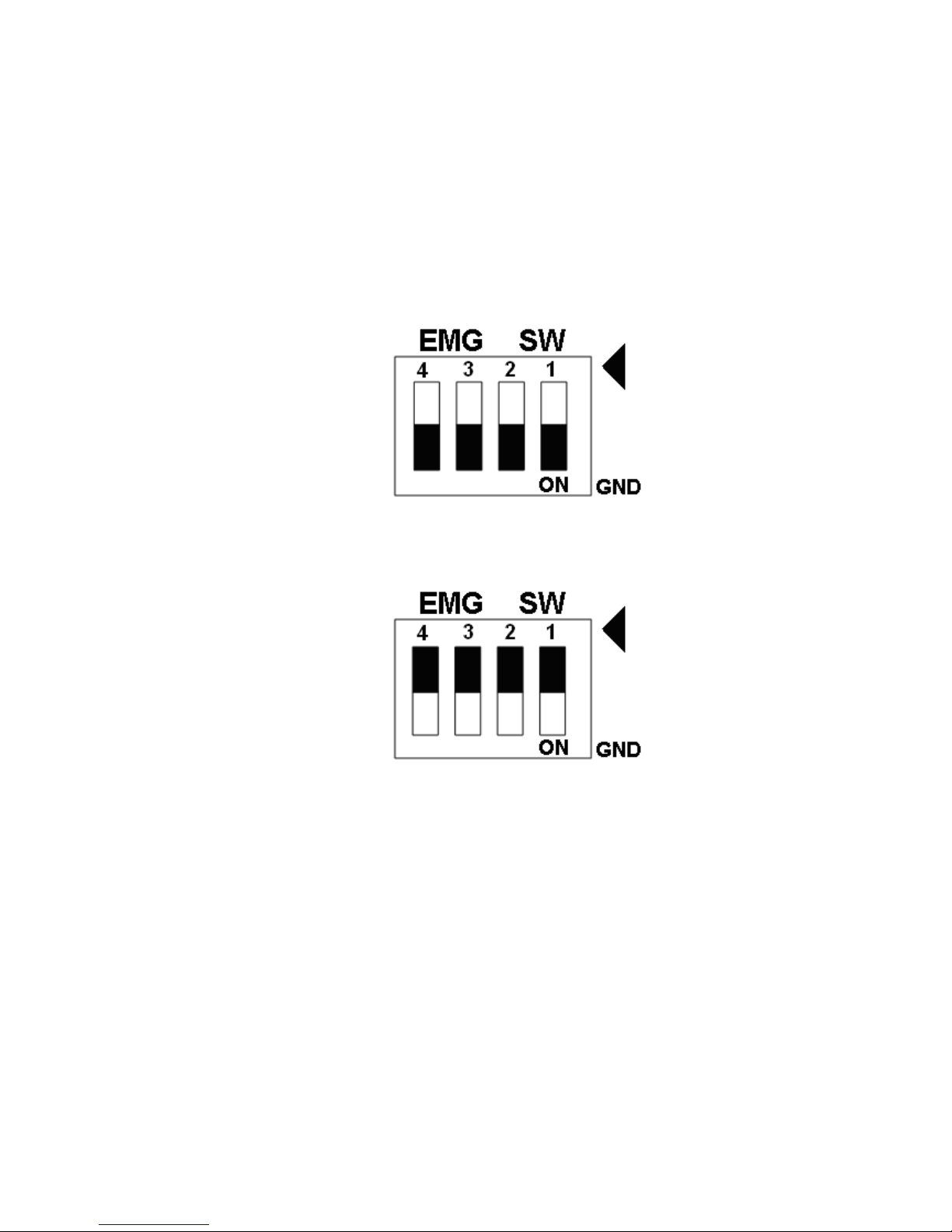
EMG SW: The EMG signals for motor axes
The emergency stop signal for each servo ampilfier can be selected from EMG SW. The
number 1, 2 , 3, 4 on EMG SW are denoted as axis X, Y, Z, U, respectively. Fig. 2.7 is the
default setting to connect the EMG singals to GND. The EMG signals from CN1 ~ CN4 will not
take effect. If the switch is disconnected as shown in Fig. 2.8, the emergency stop signals can
be controlled from EMG signals in CON6.
Fig. 2.7 EMG SW setting for normally GND (Default setting)
Fig. 2.8 EMG SW setting for user controlled signals.
Page 24
http://www.icpdas.com I8094A &I8094HGetting Started manualVer 1.3-- 24
2.3 Input/Output Connections
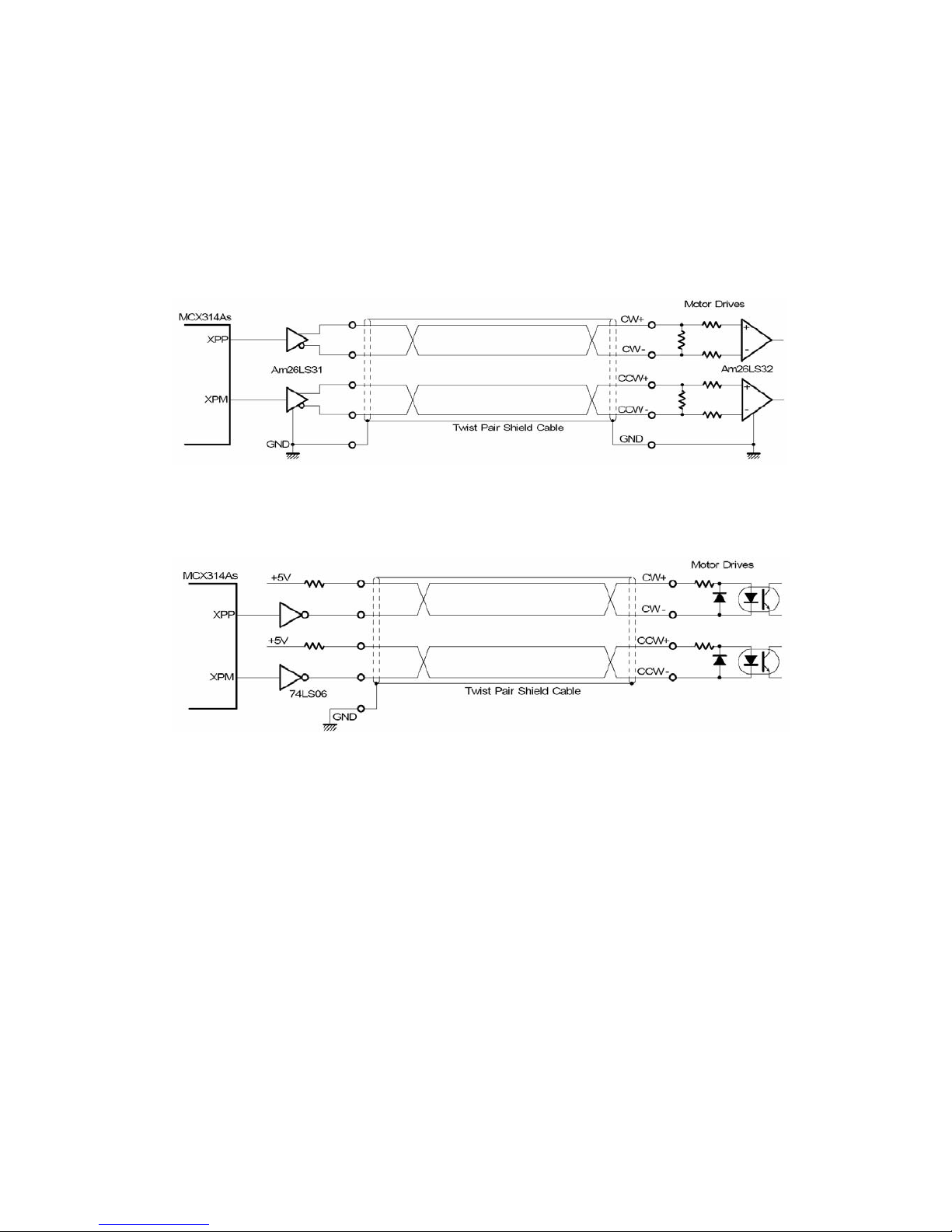
2.3.1 Pulse output signals
Differential-Type pulse output circuit
Fig. 2.8 Differential-Type pulse output circuit
Open collector output
Fig. 2.9 open collector output
Page 25
http://www.icpdas.com I8094A &I8094HGetting Started manualVer 1.3-- 25
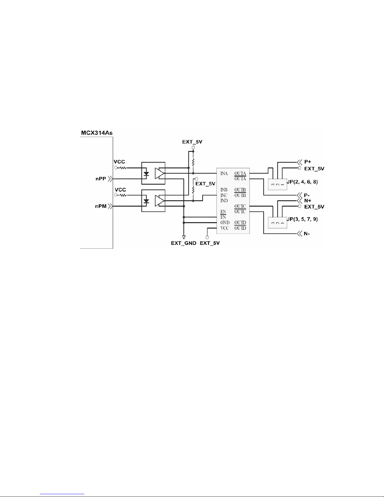
Pulse Signal Wiring Example:
I8094A/I8094H pulse output signal could be sent out by CW/CCW mode or PULSE/DIR
mode. The user could choose Differential-Type and Open-Collector Type byJP2 & JP3.
Fig. 2.10 Pulse Signal Wiring Example
Page 26
http://www.icpdas.com I8094A &I8094HGetting Started manualVer 1.3-- 26
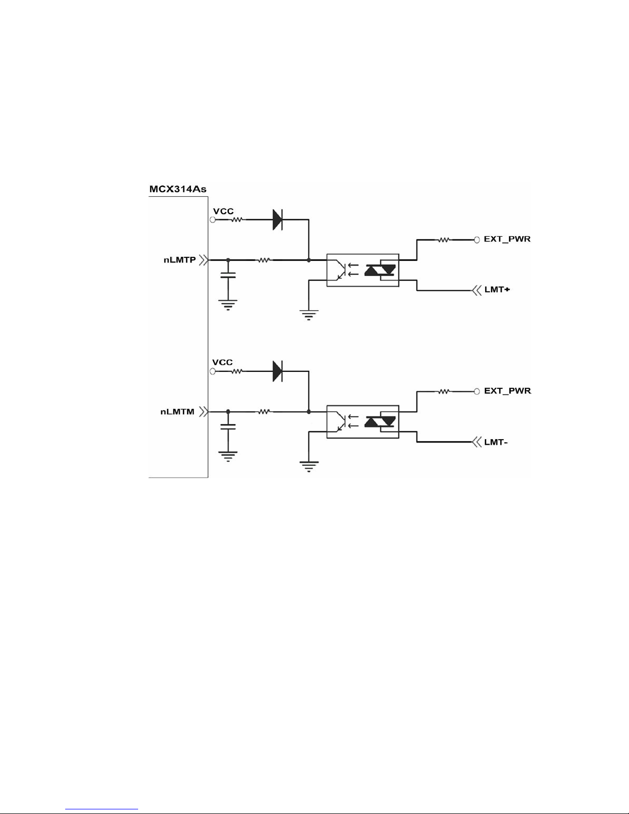
2.3.2 Connection for Limit switch Signal
Limit Switch Signal can be used to prevent over traveling appearance of the motion
system. User can set up the hardware limit switch to be normal open or normal close by
the Function Library. The following figure shows the photo couplers that are used to keep
out the sensor noise of the Limit Switch.
Fig. 2.11 Wiring sample
Page 27
http://www.icpdas.com I8094A &I8094HGetting Started manualVer 1.3-- 27
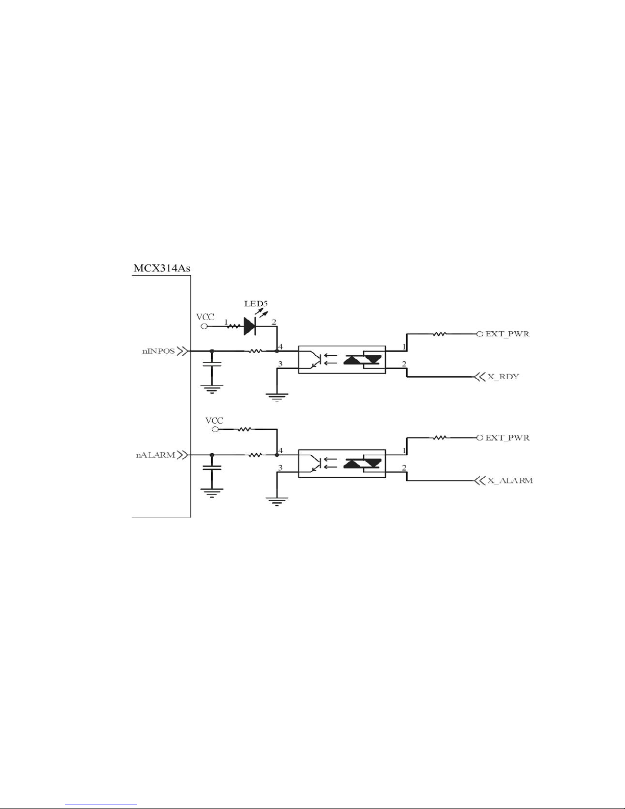
2.3.3 General Purpose DI Signals(nINPOS,nALARM)
nINPOS is a digital input signal for servo driver in-Position control. User could
enable or disable this function by Function Library.
nALARM is a digital input signal for servo driver alarm signal. The output pulse will be
stopped when I8094A/I8094H receives this signal. User could enable or disable this
function by Function Library.
Fig. 2.12 Wiring sample
Page 28
http://www.icpdas.com I8094A &I8094HGetting Started manualVer 1.3-- 28
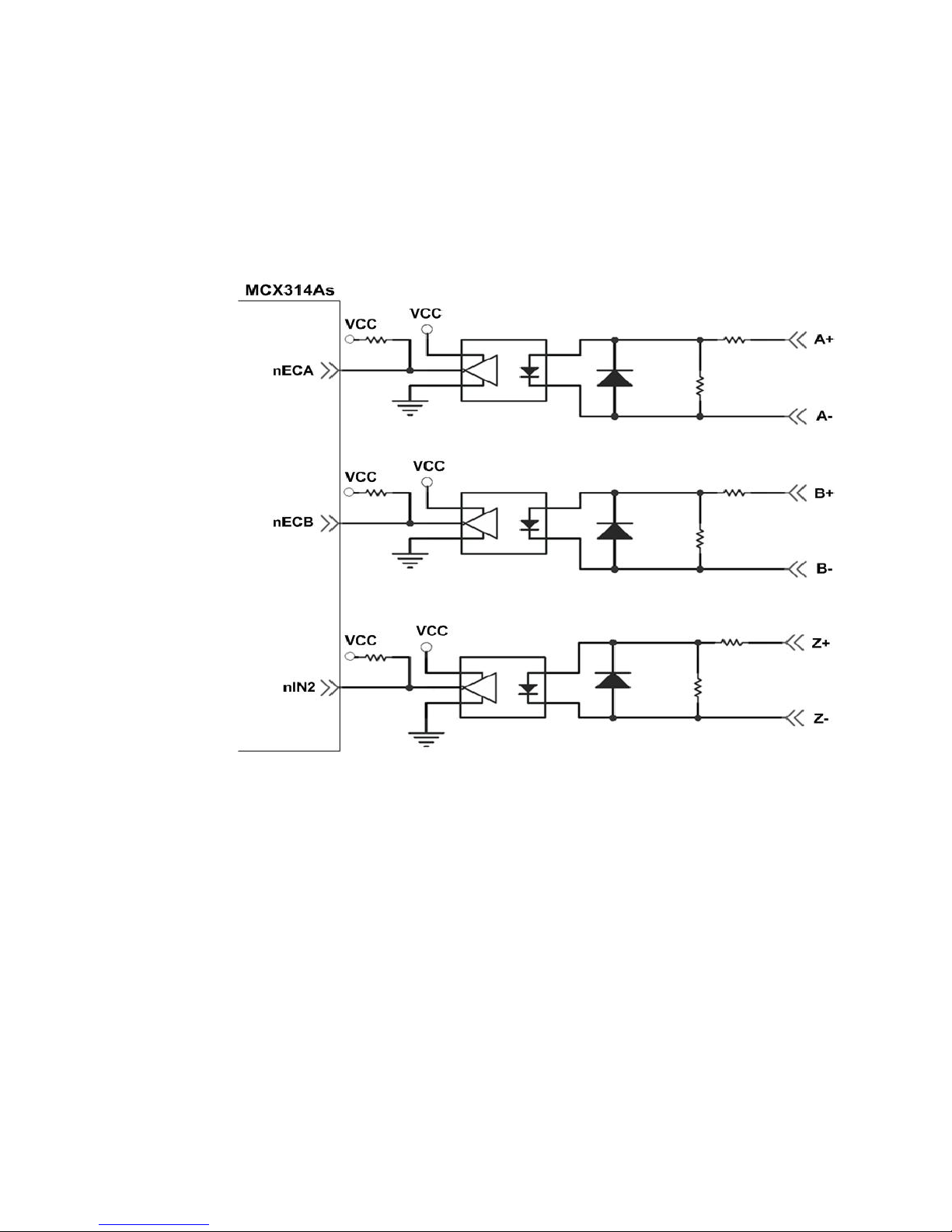
2.3.4 Encoder Signals
The following diagram shows Differential-Type encoder signals. Connect the Phase A
signal to A+ and A- pins and connect Phase B signal to B+ and B- pins. After the high
speed photo coupler isolation, the isolated encoder signals are connected to motion IC of
ASIC chip.
Fig. 2.13 Encoder signal connection
Page 29
http://www.icpdas.com I8094A &I8094HGetting Started manualVer 1.3-- 29
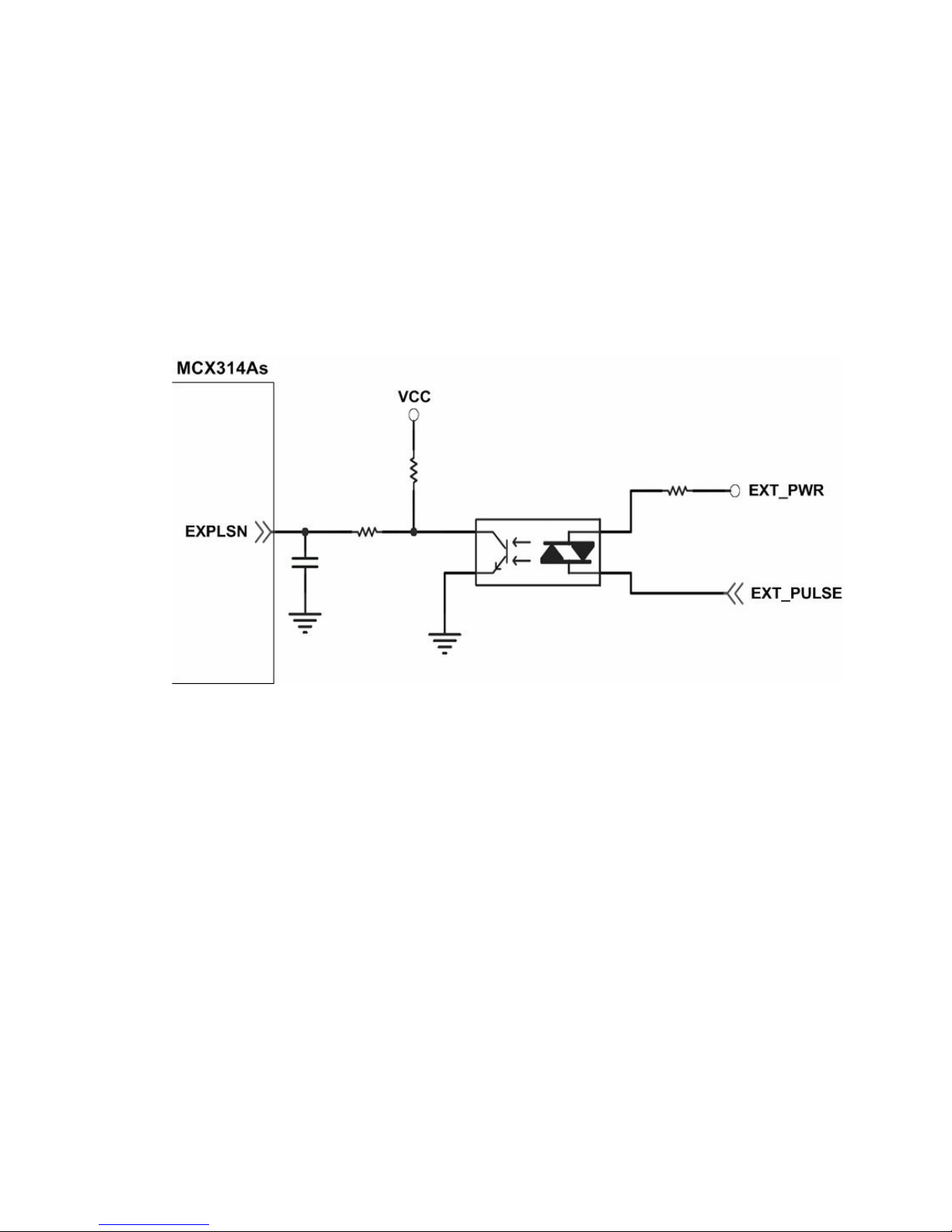
2.3.5 External pulse signal
The following diagram shows an example for external pulse signal. After the high speed
photo coupler isolation, the isolated encoder signals are connected to motion IC of ASIC
chip.
Fig. 2.14 wiring example for external pulse signal
Page 30
http://www.icpdas.com I8094A &I8094HGetting Started manualVer 1.3-- 30
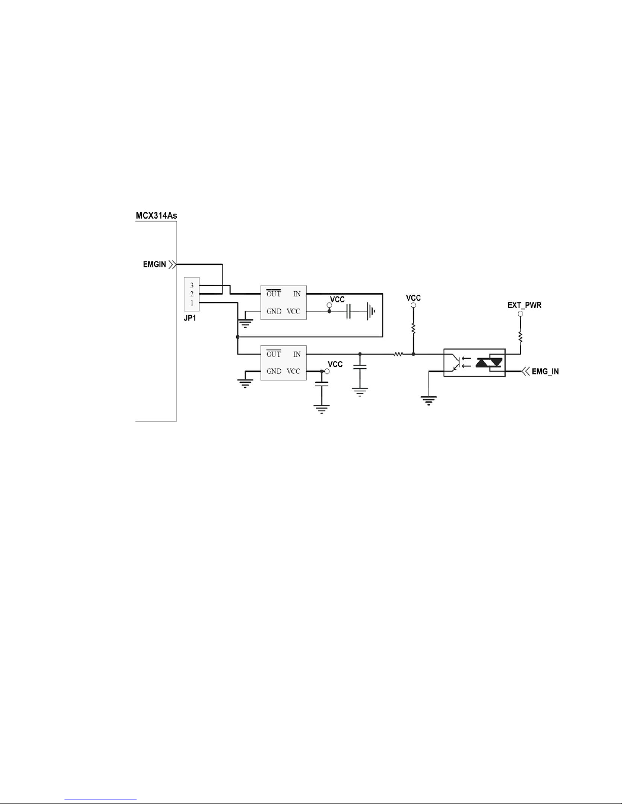
2.3.6 Emergency Stop Signal
The following diagram shows a wiring example for Emergency STOP signal. When
received emergency stop signal, all axes will be stopped and the error flag will be set as
1. After the high speed photo coupler isolation, the isolated encoder signals are
connected to motion IC of ASIC chip.
Fig. 2.15 Wiring example for emergency stop signal
Page 31

http://www.icpdas.com I8094A &I8094HGetting Started manualVer 1.3-- 31
2.3.7 External Pulse Input Signal (EXP+,EXP-)
External pulse input signal is signal for external input driver. The following diagram
shows an external signal +/- input wiring. User can set the signals as fixed pulse
CW/CCW mode, continuous pulse CW/CCW mode, or A/B phase manual pulsar mode
(please refer to section 5.1 for detail setting configuration).
Fig. 2.16 Wiring example for
External Pulse Input Signal(EXP+,EXP-)
Page 32
http://www.icpdas.com I8094A &I8094HGetting Started manualVer 1.3-- 32
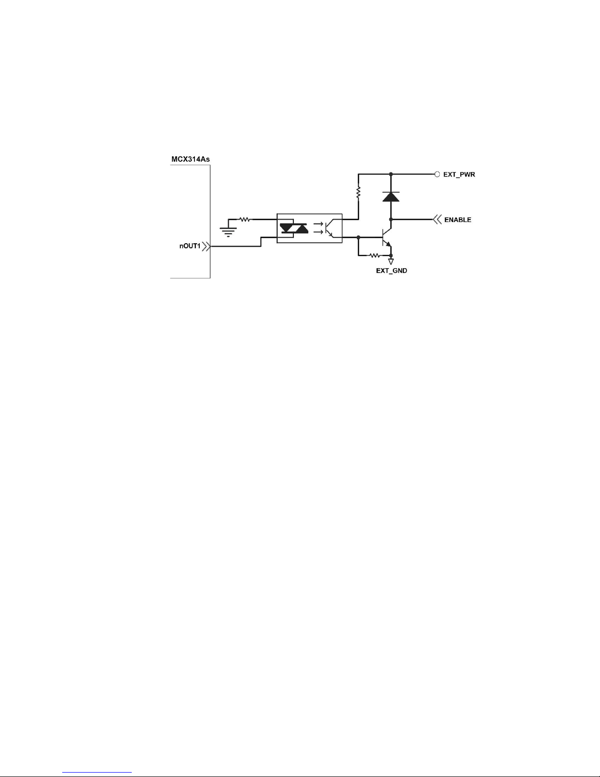
2.3.8 Servo On/Off Output Signal (ENABLE)
The following diagram shows a wiring example for output signal. This output
signal could be applied to enable or disable the driver.
Fig. 2.17 Wiring Diagram for Servo On/Off Output Signal
2.3.9 Compare Trigger Output
The following diagram is a wiring example for Trigger Output Signal. This output signal
could be adapted only on axis X and axis Y for Compare Trigger Output for specific
applications such as image capture.
Page 33

http://www.icpdas.com I8094A &I8094HGetting Started manualVer 1.3-- 33
2.4 Connection Example for Motor Driver
The following diagram is the connection example between MITSUBISH MR-J2S AC servo driver
and the extension boardDN-8468G.
Fig. 2.18 The connection between MR-J2S AC servo driver and DN-8468G extension board.
Page 34

http://www.icpdas.com I8094A &I8094HGetting Started manualVer 1.3-- 34
3 i8094A/i8094H Software Development
3.1 Software development Overview
For detail information, please refer to i8094H_star sample code.
註冊軸卡
REGISTRATION
安全IO 規劃 測試
1 緊急開關輸入
2 設定伺服馬達異常ALARM輸入
3 設定各軸前後硬體極限
4 設定各軸前後軟體極限(如必要)
是否有錯誤
GET_ERROR=
Yes
M o tio n 基本設定
1 軸輸出PULSE模式設定
2 設定軸速度輸出最大範圍
3 設定編碼器輸入參數(如需要)
4 設定數位輸入雜訊濾波功能(如需要)
5 指定軸為圓形運動軸(環狀計數器)(如 需 要)
No
取得 ERROR CODE
GET_ERROR_CODE
Motion 軸歸零
1 設定軸近原點輸入觸發邏輯(如需要)
2 設定軸原點輸入觸發邏輯
3 設定軸歸零速度
4 設定歸零模式
5 啟動軸歸零
Motion 設定
設定加減速模式
設定初始速度
設定速度
設定加減速度
Motion 動作
固定脈波數輸出
連續脈波輸出
等待完成軸運動
多軸同時運動
多軸補間運動控制
手動外部輸入 M otion 動作 (如 需要 )
1 手輪脈波驅動
2 固定脈波驅動
3 連續脈波驅動
4 外部輸入關閉
Page 35

http://www.icpdas.com I8094A &I8094HGetting Started manualVer 1.3-- 35
3.1.1 Register Module
You are required to register your 8094/I8094F module before starting to send any
command, or your will receive an error message. Please refer to
“i8094H_Manual_1.3tc.pdf section 2.2” i8094H_REGISTRATION()” for more detail
information.
3.2 Safety IO Setting (Troubleshooting for Motion not working)
3.2.1 Emergency Stop Signal Input
The emergency stop switch is used for stopping an undesired motion for emergency
situation; the user could immediately stop Motion action to ensure human/machine
safety.
If you would like to disable Emergency Stop Signal, please close breaks between 2 and
3 pin of JP1.
If you would like to enable Emergency Stop Signal, please close breaks between 1 and 2
pin of JP1. Please connect EMG_IN to (N.C), and install the switch in an appropriate
location.
3.2.2 Configure the Servo ALARM Signals
These signals will be input when there are ALARM occurred on servomotor drivers, therefore the
user will be able to get notification immediately for further actions. You could set up operating
mode (Enable or Disable) or select proper trigger level of these signals.
Please refer to Manual “i8094H_Manual_1.3tc.pdf” section 2.13, function
i8094H_SET_ALARM() for detail settings.
Page 36

http://www.icpdas.com I8094A &I8094HGetting Started manualVer 1.3-- 36
3.2.3 Configure the Limit Switch Signals(±EL)
To insure the safety of machine, hardware limit switches are placed at the both ends of machine
traveling range. When the hardware limit switch sensors detect the machine, PISO-PS400 will
stop immediately. You could set up operating mode (Enable or Disable) or select proper trigger
level of these signals.
Please refer to Manual “i8094H_Manual_1.3tc.pdf” section 2.6, function
i8094H_SET_HLMT() for detail settings.
3.2.4 Configure the Software Limit(±SEL)
To insure the safety of machine, hardware limit switches are placed at the both ends of machine
traveling range. However, you could also set up software limits for earlier detection before
hardware limit can take effect. When it reaches the software limit, PISO-PS400 will stop
immediately. You could set up operating mode (Enable or Disable) or select proper trigger
conditions of these signals.
Please refer to Manual “i8094H_Manual_1.3tc.pdf” section 2.10, function
i8094H_SET_SLMT() & i8094H_CLEAR_SLMT() for detail settings.
3.3 Error Checking(GET_ERROR)
When error occurs, you could get the error-code by GET_ERROR_CODE() to check out
error message and perform troubleshooting. The user could also check all DI status to
ensure DI input accuracy.
Please refer to Manual “i8094H_Manual_1.3tc.pdf” section 3.5, function
i8094H_GET_DI() for detail settings.
Page 37

http://www.icpdas.com I8094A &I8094HGetting Started manualVer 1.3-- 37
3.4 Motion Basic Configuration
Motion basic configuration that required for general purposes are as follow:
1. Pulse output mode setting: Pulse/Dir、CW/CCW…
i8094MF_SET_PULSE_MODE() (Please refer to Manual “i8094H_Manual_1.3tc.pdf”
section 2.4, function i8094H_SET_PULSE_MODE() for detail settings.)
2. Set up Max. speed limitation for each axis
(Please refer to Manual “i8094H_Manual_1.3tc.pdf” section 2.5, function
i8094H_SET_MAX_V () for detail settings.)
3. Encoder input setting (optional)
(Please refer to Manual “i8094H_Manual_1.3tc.pdf” section 2.11, function
i8094H_SET_ENCODER() for detail settings.)
4. DI noise filter setting( optional)
(Please refer to Manual “i8094H_Manual_1.3tc.pdf” section 2.15, function
i8094H_SET_FILTER() for detail settings.)
5. Circular motion declaration( Ring counter)( optional)
(Please refer to Manual “i8094H_Manual_1.3tc.pdf” section 2.16, function
i8094H_VRING_ENABLE() for detail settings.)
Page 38

http://www.icpdas.com I8094A &I8094HGetting Started manualVer 1.3-- 38
3.5 Manual Pulse Generator Testing (Optional)
The user could perform pulse generator function manually to drive forward or backward motion.
This operation could ensure if the DI signals are functioning normally and if the direction(+/-) is
correct, therefore the users could make further adjustments for lines and parameters.
The following gives you further information on three ways to initiate Manual Pulse Generator
Testing:
1. A/B phase Manual Pulse Generator:
Use the A/B phase Manual Pulse Generator for forward/backward moving.
(Please refer to Manual “i8094H_Manual_1.3tc.pdf” section 2.18.1, function i
i8094H_EXD_MP()for detail settings.)
2. Fixed-pulse driving Manual Pulse Generator: The users could preset the driving
pulses at a fixed intensity and when press the forward or backward button, the motor
will move a few steps(Pulse) forward or backward.
(Please refer to Manual “i8094H_Manual_1.3tc.pdf” section 2.18.2, function
i i2.18.2” i8094H_EXD_FP() for detail settings.)
3. Continuous- pulse driving Manual Pulse Generator: The users could preset the
output-pulse frequency at a fixed velocity (Hz)
, the motor will keep on moving forward or
backward at fixed velocity when pressing the forward or backward button and the motion
will be stopped immediately when releasing the button.
(Please refer to Manual “i8094H_Manual_1.3tc.pdf” section 2.18.3, function
i8094H_EXD_CP() for detail settings.)
Page 39

http://www.icpdas.com I8094A &I8094HGetting Started manualVer 1.3-- 39
4. Disable external pulse input:
This command is for disabling the external pulse input operated by any of the three
functions above.
Please refer to Manual “i8094H_Manual_1.3tc.pdf” section 2.18.4, function
i8094H_EXD_DISABLE() for detail settings.
Page 40

http://www.icpdas.com I8094A &I8094HGetting Started manualVer 1.3-- 40
3.6 Home Search
I8094A/I8094H offers automatic home search function; if providing with proper settings,
it would function automatically. The main steps are as bellows:
z Near-home sensor searching under high-speed motion.
z Home sensor searching under low-speed motion.
z Servomotor Z-phase searching under low-speed motion.
z Offset movement to the origin of the working area under high-speed motion.
A few steps could be skipped to adjust settings accordingly to meet customers’ actual
needs. This operation could be performed automatically, therefore economize on CPU
resource and reduce programming efforts. Even though there are only four home search
steps, by software functions adjustments that offers home search direction
configurations and with the variations being made by skipping certain steps, there are
actually more than 10 home search modes provided.
3.6.1 Home Search Configuration
1. Logic level setting for Near home sensor and Home sensor (optional):
Please refer to Manual “i8094H_Manual_1.3tc.pdf” section 2.8, function
i8094H_SET_NHOME() for detail settings.
2. Home sensor logic level setting:
Please refer to Manual “i8094H_Manual_1.3tc.pdf” section 2.9, function
i8094H_SET_HOME_EDGE() for detail settings.
3. Home-speed setting:
Please refer to Manual “i8094H_Manual_1.3tc.pdf” section 5.1, function
i8094H_SET_HV() for detail settings.
Please refer to Manual “i8094H_Manual_1.3tc.pdf” section 6.1.2, function
i8094H_SET_SV() for detail settings.
4. Home mode setting:
Please refer to Manual “i8094H_Manual_1.3tc.pdf” section 5.3, function
i8094H_SET_HOME_MODE() for detail settings.
Page 41

http://www.icpdas.com I8094A &I8094HGetting Started manualVer 1.3-- 41
3.6.2 Running the Home Search
1 Start homing:
Please refer to Manual “i8094H_Manual_1.3tc.pdf” section 5.4, function
i8094H_HOME _START() for detail settings.
2 Waiting for completing homing operation:
Please refer to Manual “i8094H_Manual_1.3tc.pdf” section 6.5.3, function
i8094H_STOP_WAIT() for detail settings.
Please refer to Manual “i8094H_Manual_1.3tc.pdf” section 7.2.7, function
i8094H_MP_STOP_WAIT() for detail settings.
Page 42

http://www.icpdas.com I8094A &I8094HGetting Started manualVer 1.3-- 42
3.7 Basic Motion
3.7.1 Speed Profile of the Motion Control
1 Symmetrical T-profile of motion velocity
(If SV is larger than V or equal to V, perform constant velocity driving)
2 Asymmetrical T-profile of motion velocity
Page 43

http://www.icpdas.com I8094A &I8094HGetting Started manualVer 1.3-- 43
3 Symmetrical S-curve of motion velocity
4 Asymmetrical S-curve of motion velocity
Page 44

http://www.icpdas.com I8094A &I8094HGetting Started manualVer 1.3-- 44
3.7.2 Basic Settings For Single Axis
1. Setting the mode of Acceleration/deceleration: There are four speed modes of
operation:
0 Æ Symmetrical T-Profile (SV、V、A、AO)
1 Æ Symmetrical S-curve (SV、V、K、AO)
2 Æ Asymmetrical T-profile (SV、V、A、D、AO)
3 Æ Asymmetrical S-curve (SV、V、K、L、AO)
Please refer to Manual “i8094H_Manual_1.3tc.pdf” section 6.1.1, function
i8094H_NORMAL_SPEED() for detail settings.
2. Setting the start velocity: Set lowest speed:
Please refer to Manual “i8094H_Manual_1.3tc.pdf” section 6.1.2, function
i8094H_SET_SV() for detail settings.
3. Setting the Velocity: Set the speed at a certain rate:
Please refer to Manual “i8094H_Manual_1.3tc.pdf” section 6.1.3, function
i8094H_SET_V() for detail settings.
4. Setting the Acceleration/Deceleration speed: Set the Acceleration/Deceleration
speed at a certain rate:
Please refer to Manual “i8094H_Manual_1.3tc.pdf” section 6.1.4, function i
i8094H_SET_A() for detail settings.
Please refer to Manual “i8094H_Manual_1.3tc.pdf” section 6.1.5, function
i8094H_SET_D() for detail settings.
Page 45

http://www.icpdas.com I8094A &I8094HGetting Started manualVer 1.3-- 45
3.7.3 Basic Motion of Single Axis
1. Fixed-pulse driving output: Perform fixed-quantity of single axis pulse output.
Please refer to Manual “i8094H_Manual_1.3tc.pdf” section 6.1.9, function
i8094H_FIXED_MOVE() for detail settings.
2. Continuous-pulse driving output: Perform continuous pulse output of single axis.
Please refer to Manual “i8094H_Manual_1.3tc.pdf” section 6.1.10, function
i8094H_CONTIUNE_MOVE ()for detail settings.
3. Waiting for motion done: Waiting for finishing the axis driving operation.
Please refer to Manual “i8094H_Manual_1.3tc.pdf” section 6.5.3, function
i8094H_STOP_WAIT() for detail settings.
Please refer to Manual “i8094H_Manual_1.3tc.pdf” section 7.2.7, function
i8094H_MP_STOP_WAIT() for detail settings.
Page 46

http://www.icpdas.com I8094A &I8094HGetting Started manualVer 1.3-- 46
3.7.4 Basic Setting of Muti-Axes Interpolation
1. Setting axes of interpolation: Select the axes that are required to perform
interpolation.
Please refer to Manual “i8094H_Manual_1.3tc.pdf” section 6.2.1, function
i8094H_AXIS_ASSIGN() for detail settings.
2. Setting the mode of Acceleration/Deceleration of vector: There are twelve modes:
0 Æ 2-axes( Linear & ARC & Circular) Fixed-vector velocity (VV)
1 Æ 2-axes linear symmetrical T-profile (VSV、VV、VA、VAO)
2 Æ 2-axes linear symmetrical S-curve (VSV、VV、VK、VAO)
3 Æ 2-axes linear asymmetrical T-profile (VSV、VV、VA、VD、VAO )
4 Æ 2-axes linear asymmetrical S-curve (VSV、VV、VK、VL、VAO)
5 Æ 2-axes (ARC & Circular) symmetrical T-profile (VSV、VV、VA、VAO )
6 Æ 2-axes (ARC & Circular) asymmetrical T-profile (VSV、VV、VA、VD、VAO )
7 Æ 3-axesFixed-vector velocity (VV)
8 Æ 3-axes linear symmetrical T-profile (VSV、VV、VA、VAO)
9 Æ 3-axes linear symmetrical S-curve (VSV、VV、VK、VAO)
10 Æ 3-axes linear asymmetrical T-profile (VSV、VV、VA、VD、VAO )
11 Æ 3-axes linear asymmetrical S-curve (VSV、VV、VK、VL、VAO )
Please refer to Manual “i8094H_Manual_1.3tc.pdf” section 6.2.2, function
i8094H_VECTOR_SPEED() for detail settings.
3. Setting the start vector velocity: Set the lowest vector speed.
Please refer to Manual “i8094H_Manual_1.3tc.pdf” section 6.3.3, function
i8094H_SET_VSV() for detail settings.
4. Setting the vector velocity: Set the vector speed at a certain rate
Please refer to Manual “i8094H_Manual_1.3tc.pdf” section 6.3.4, function
i8094H_SET_VV() for detail settings.
5. Setting the velocity of Acceleration/Deceleration of vector: Set the speed of
Acceleration/Deceleration of vector at a certain rate.
Please refer to Manual “i8094H_Manual_1.3tc.pdf” section 6.3.5, function
i8094H_SET_VA() for detail settings.
Please refer to Manual “i8094H_Manual_1.3tc.pdf” section 6.3.6, function
i8094H_SET_VD() for detail settings.
Page 47

http://www.icpdas.com I8094A &I8094HGetting Started manualVer 1.3-- 47
3.7.5 Basic Motion of Muti-Axes Interpolation
1. 2-axes linear interpolation: Perform 2-axes linear interpolation.
Please refer to Manual “i8094H_Manual_1.3tc.pdf” section 6.2.10, function
i8094H_LINE_2D() for detail settings.
2. 3-axes linear interpolation: Perform 3-axes linear interpolation.
Please refer to Manual “i8094H_Manual_1.3tc.pdf” section 6.2.11, function
i8094H_LINE_3D() for detail settings.
3. 2-axes ARC interpolation: Perform 2-axes ARC interpolation.
Please refer to Manual “i8094H_Manual_1.3tc.pdf” section 6.2.12, function
i8094H_ARC_CW() for detail settings.
Please refer to Manual “i8094H_Manual_1.3tc.pdf” section 6.2.12, function
i8094H_ARC_CCW() for detail settings.
4. 2-axesCircular interpolation: Perform 2-axes Circular interpolation.
Please refer to Manual “i8094H_Manual_1.3tc.pdf” section 6.2.13, function
i8094H_CIRCLE_CW() for detail settings.
Please refer to Manual “i8094H_Manual_1.3tc.pdf” section 6.2.13, function
i8094H_CIRCLE_CCW() for detail settings.
Page 48

http://www.icpdas.com I8094A &I8094HGetting Started manualVer 1.3-- 48
3.8 Advance Motion
1. 2-axes continuous interpolation of rectangle: Perform2-axes continuous
interpolation of rectangle.
Please refer to Manual “i8094H_Manual_1.3tc.pdf” section 6.4.1, function
i8094H_RECTANGLE() for detail settings.
2. 2-axes continuous interpolation of line:
Initial setting for continuous interpolation of 2-axes line(Symmetrical T-profile).
Please refer to Manual “i8094H_Manual_1.3tc.pdf” section 6.4.2, function
i8094H_LINE_2D_INITIAL() for detail settings.
Perform 2-axes continuous interpolation of line.
Please refer to Manual “i8094H_Manual_1.3tc.pdf” section 6.4.2, function
i8094H_LINE_2D_CONTINUE() for detail settings.
3. 3-axes continuous interpolation of line:
Initial setting for continuous interpolation of line( symmetrical T-profile).
Please refer to Manual “i8094H_Manual_1.3tc.pdf” section 6.4.3, function
i8094H_LINE_3D_INITIAL() for detail settings.
Perform 3-axes continuous interpolation of line.
Please refer to Manual “i8094H_Manual_1.3tc.pdf” section 6.4.3, function
i8094H_LINE_3D_CONTINUE() for detail settings.
4. Others continuous interpolation: Muti-point continuous interpolation, 3-axes Helix
interpolation, 2-axes Ratio motion
Please refer to Manual “i8094H_Manual_1.3tc.pdf” section 6.4.4~6.4.10 for detail
information.
Page 49

http://www.icpdas.com I8094A &I8094HGetting Started manualVer 1.3-- 49
3.9 Motion Synchronization Action
i8094A/i8094H provides a lot of functions that support Synchronization Action, such as
comparison of EP, LATCH…and so on.
Please refer to Manual “i8094H_Manual_1.3tc.pdf” section 6.4.4~6.4.10 for detail
informaion.
Page 50

http://www.icpdas.com I8094A &I8094HGetting Started manualVer 1.3-- 50
4 SOFTWARE GETTING STARTED GUIDE
4.1 WinCon eVC++
4.1 WinCon eVC++ Guideline
4.1.1 Files you will need
Please make sure you get the following files in your PC:
1. I8094h.lib
2. I8094h.dll
3. I8094h.h
If you don’t have these files, please find them in the CD that comes along with
the device, or you could download the latest version from ICPDAS’s website
http://www.icpdas.com/download/download-list.htm .
4.1.2 Create a new eVC++ Application Project
1. Install and execute Microsoft eVC++ 4.0.
2. Click File -> New to create a new application project.
3. In Projects property page, select WCE MFC AppWizard (exe)
4. In Projects property page, specify the project name as Demo_First.
5. In Projects property page, key in or browse the disk path in the field “Location”.
6. In Projects property page, check Win 32[WCE ARMV4] in CPUs list.
7. If necessary, please also select others options together. And then click OK.
Page 51

http://www.icpdas.com I8094A &I8094HGetting Started manualVer 1.3-- 51
8. Choose Dialog based and click NEXT
9. Click Finish to end establishment of the new project.
Page 52
http://www.icpdas.com I8094A &I8094HGetting Started manualVer 1.3-- 52
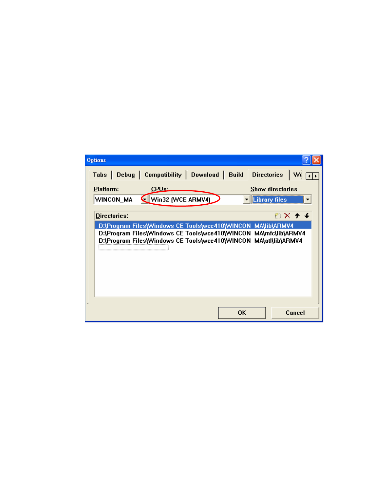
4.1.3 Add the Reference Path into eVC++ Application Project
A. On the
Tools
menu, click
Options
. The
Options
popup menu will appears.
B. Click on tab Directories, choose Platform to be WINCON_MA, select “Win32
[WCE ARMV4] in the CPUs list.
C. Specify the path of Include files and Library files. To add the path, double-click
on the blank line at the end of the Directories list. Please key in the specific path
that your header files located. For example, C:\DAQPRO\Wincon\inc.
Page 53

http://www.icpdas.com I8094A &I8094HGetting Started manualVer 1.3-- 53
4.1.4 Start the eVC++ Sample
Add a BUTTON on Dialog, as below:
Double-click on BUTTON to create a subprogram; declare the following header files.
#include "WinConSDK.h"
#include "i8094H.h"
Page 54

http://www.icpdas.com I8094A &I8094HGetting Started manualVer 1.3-- 54
On the Tools menu, click Options. The Options popup menu will appears.
Select menu Project->Setting, will bring up a dialog box as below, click on tab Link,
key in WinConSDK.lib i8094.lib(showing as below) into the Object/library modules
box and the click OK.
Page 55

http://www.icpdas.com I8094A &I8094HGetting Started manualVer 1.3-- 55
4.2 WinCon Microsoft Visual Studio .NET 2003(VB.NET,C#)
Reserved
4.3 I-8000 Turbo C++
Reserved
Page 56

http://www.icpdas.com I8094A &I8094HGetting Started manualVer 1.3-- 56
5 MPTool : EzMake
5.1 Start EzMake
To start your EzMake, you could:
1. StartÆProgramsÆ EzMake, click on EzMake to start the program.
2. Go to \CompactFlash\EzProg-I\EzMake\EzMake.exe, double click on the file
EzMake.exe to start the program.
5.2 Specify the I-8094H to be used
All the I-8094H modules will be display on EzMake default page, select the I-8094H in
use and click on OK.
Note: the I-8094H in use will display Used.
Fig. 5.1 EzMake default page
Page 57

http://www.icpdas.com I8094A &I8094HGetting Started manualVer 1.3-- 57
5.3 Operation Page
There are 7 blocks, the general operation order is as follow: Tree Diagram Æ Main Menu
Æ Control Button ÆFunction Library Groups MenuÆFunction Display Menu ÆFunction
& Parameter Editor ÆMessage & Status
5.3.1 Tree Diagram
There are four branches under the Tree Diagram
Initial Table: Edit I-8094Hinitial settings
Macro Problem: Create MP
Interrupt Service Routine: Create ISR
Machine Data: Edit data for power outage carry-over
Page 58

http://www.icpdas.com I8094A &I8094HGetting Started manualVer 1.3-- 58
5.3.2 Main Menu
After you select the file type to open or create a file, you could select the operations to be
performed from Main Menu or buttons on toolbar.
5.3.2.1 Create a File
Please follow the steps to create a file:
In Initial Table, you could only edit functions that is displayed in Functions &
Parameters Editor (Fig. 5.2)
Fig. 5.2 Initial Table
Page 59
http://www.icpdas.com I8094A &I8094HGetting Started manualVer 1.3-- 59
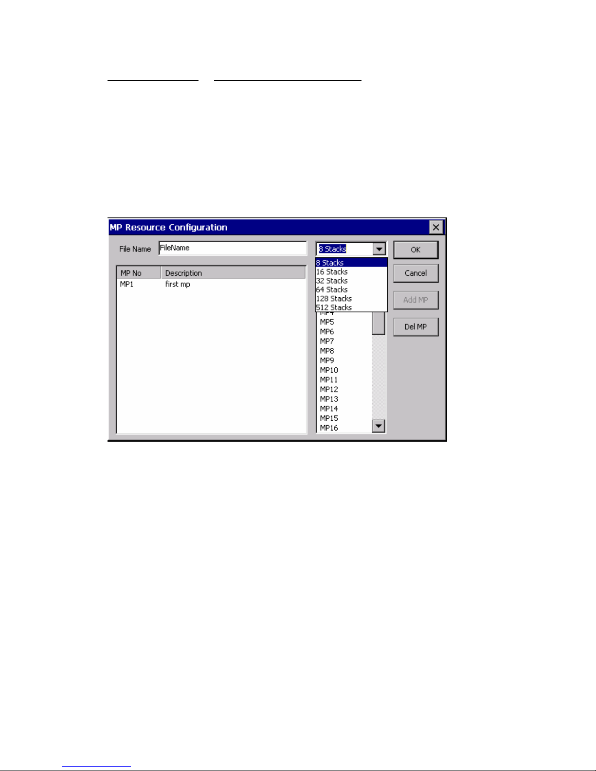
Macro Program & Interrupt Service Routine
1.
Input filename (less than 10 characters), as shown in Fig. 5.3
2.
Select the MP you would like to add on (MP1~MP157), among158 MP, there are
totally 5 categories stacks(8/16/32/128/512), add them according to requirements.
For ISR, it is similar to MP, however the number of Functions and ISR are less.
3. You could edit Description after you adding on MP.
4.
Press OK to finish creating file.
Fig. 5.3 MP Resouse Configuration
Page 60

http://www.icpdas.com I8094A &I8094HGetting Started manualVer 1.3-- 60
5.3.2.2 Open a file
The default path for saving files will be: CompactFlash\EzProg-I\EzMake\
If you select MacroProgram in Tree Diagram, you could only open the file with .mp
extension name.
Page 61

http://www.icpdas.com I8094A &I8094HGetting Started manualVer 1.3-- 61
5.3.3 Function & Parameter Editor
You could edit the parameters in Function & Parameter Editor.
Fig. 5.4
Fig. 5.4 shows the Initial Table, you could edit the functions displayed, but you could not
add or delete the functions. To edit the functions, double click on the function you would
like to edit will bring up a editor window, input the parameters you’d like to make a
change of. You could also edit Macro Program and Interrupt Service Routine. Note that
Machine Data is for data storage, it is different the other three(Fig. 5.5)
Fig. 5.5 MD Resource Configuration
Page 62

http://www.icpdas.com I8094A &I8094HGetting Started manualVer 1.3-- 62
5.3.4 Function Library Groups Menu
After you create a new file, you could add the functions you need.
In Function Library Groups Menu, you could select the Functions by groups or choose
the last one (Full Functions) to select all functions.
5.3.5 Function Display Menu
When you click on the Function groups displayed on Function Library Groups Menu, it
will shows all functions in this group, select the function you’d like to add on and edit its
parameters.
Fig. 5.6
Page 63

http://www.icpdas.com I8094A &I8094HGetting Started manualVer 1.3-- 63
5.3.6 Message & Status
5.3.6.1 Message
If you place your mouse cursor over any button, the detail function information will be
displayed in this window.
5.3.6.2 Axis Status
After you execute MP or ISR, various statuses will be shown in the window.
5.3.6.3 Hardware Signals
After you execute MP or ISR, the corresponding LED indicators for Axes statuses and
locations will be light-on.
Page 64
http://www.icpdas.com I8094A &I8094HGetting Started manualVer 1.3-- 64
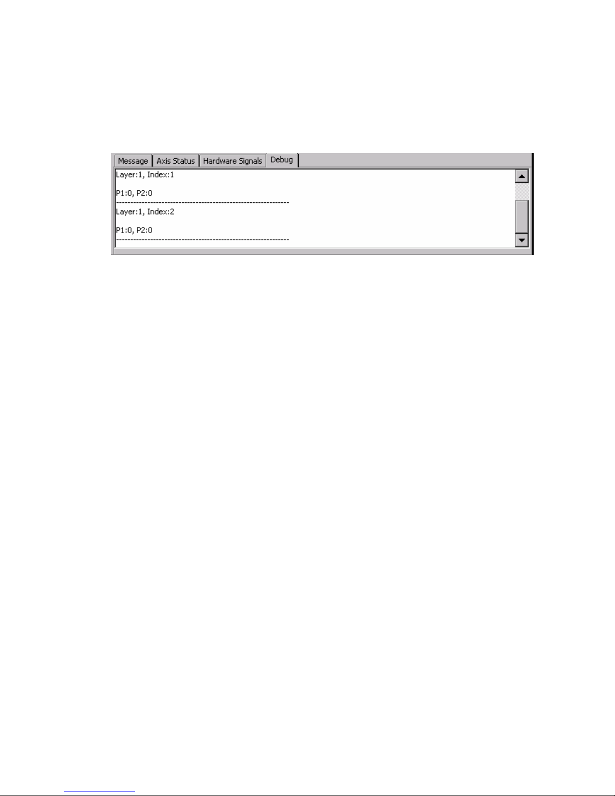
5.3.6.4 Debug
After you execute MP or ISR, this window will display the location where the executed
functions being made a change of.
Page 65
http://www.icpdas.com I8094A &I8094HGetting Started manualVer 1.3-- 65
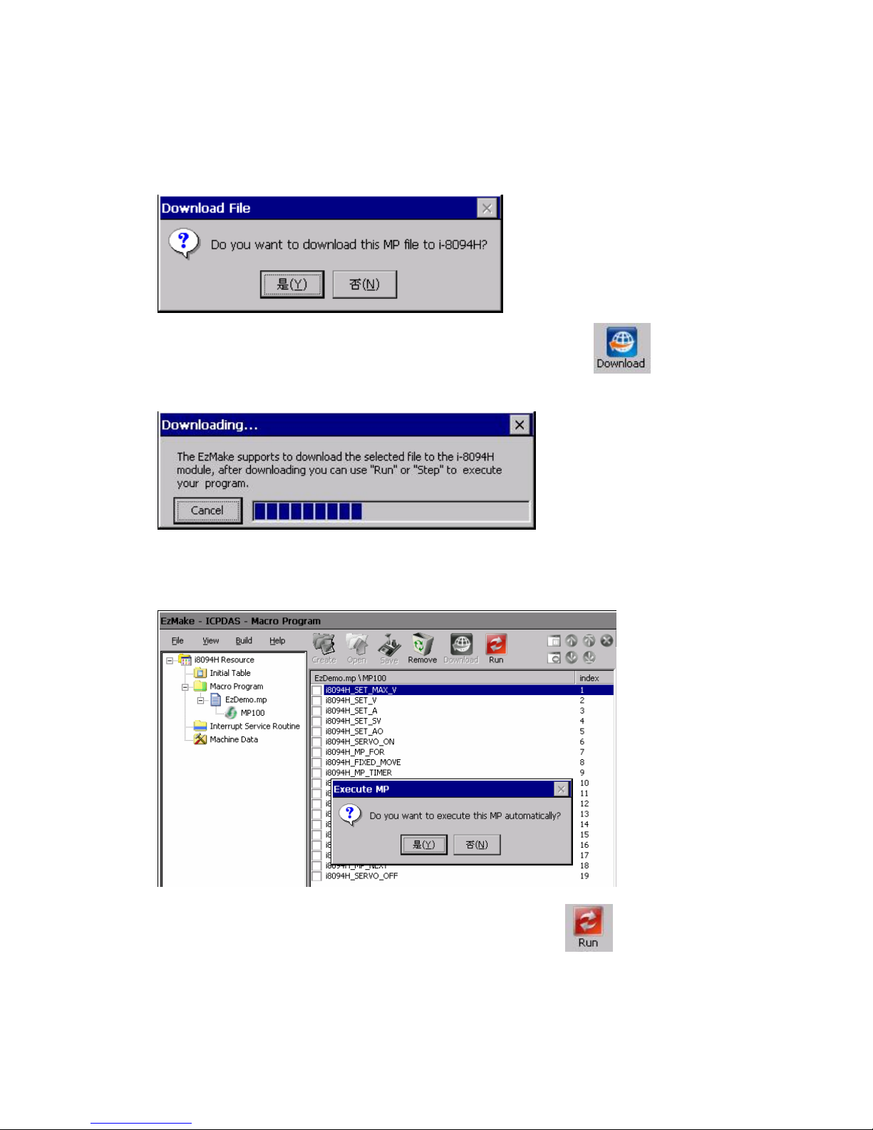
5.4 Download files and programs execution
5.4.1 Download the file
Select the file(*.it/*.mp/*.isr/*.md) you’d like to download, click to download the
program (Fig. 5.7)
Fig. 5.7 Downloading
5.4.2 Program execution
Select the files (MPxx/ISRxx) you want to download, click , the program will be
executed immediately.
Page 66

http://www.icpdas.com I8094A &I8094HGetting Started manualVer 1.3-- 66
APPENDIX A
A.1 Setup the Development Environment of I8094A/I8094H
A.1.1 eVC ++ 4.0
1. Microsoft eVC++ 4.0: ServicPack2 or above ( current version: ServicPack4)
2. WinCon8000_EVC4_SP1: WinCon in eVC++ Development Environment
(SA_IA)
3. WinConSDK:WinCon Software Tool(inc,lib,dll,demo…)
Page 67
http://www.icpdas.com I8094A &I8094HGetting Started manualVer 1.3-- 67
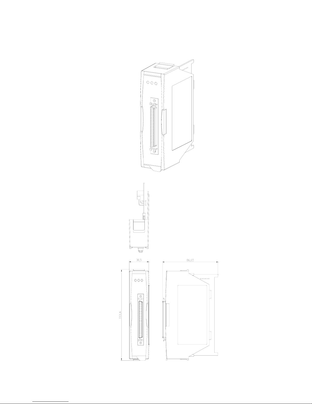
A.2 Appearance and Dimension
Page 68

http://www.icpdas.com I8094A &I8094HGetting Started manualVer 1.3-- 68
APPENDIX B DN-8468 series daughter board
B.1 DN-8468M Daughter Board
The DN-8468M is the daughter board for Mitsubitch J2 Series Amplifier. It has 4-axis I/O
signals.
B.1.1 Board Layout for DN-8468M
TB1
RJ1
JP1 JP2
CN-XACN-XBCN-ZBCN-ZA
CN1CN7 CN3
CN-YACN-YBCN-UBCN-UA
CN6CN2CN8 CN4
CON1
68 PIN SCSI
EMG
SW
TB2
JP5
JP4 JP3
X Y
Z U
DN-8468M
107mm
162mm
CN5
Fig. 1-1 Board layout for the DN-8468M
Page 69

http://www.icpdas.com I8094A &I8094HGetting Started manualVer 1.3-- 69
Page 70
http://www.icpdas.com I8094A &I8094HGetting Started manualVer 1.3-- 70
B.1.2 Signal Connections for DN-8468M
Maintaining signal connections is one of the most important factors in ensuring that your
application system is sending and receiving data correctly.
Pin Assignment for CON1
The I/O connector on the DN-8468M is a 68-pin SCSI II connector that enables you to connect to
the PISO-PS400 motion card. Please refer to the section 2.2.1( page 15).
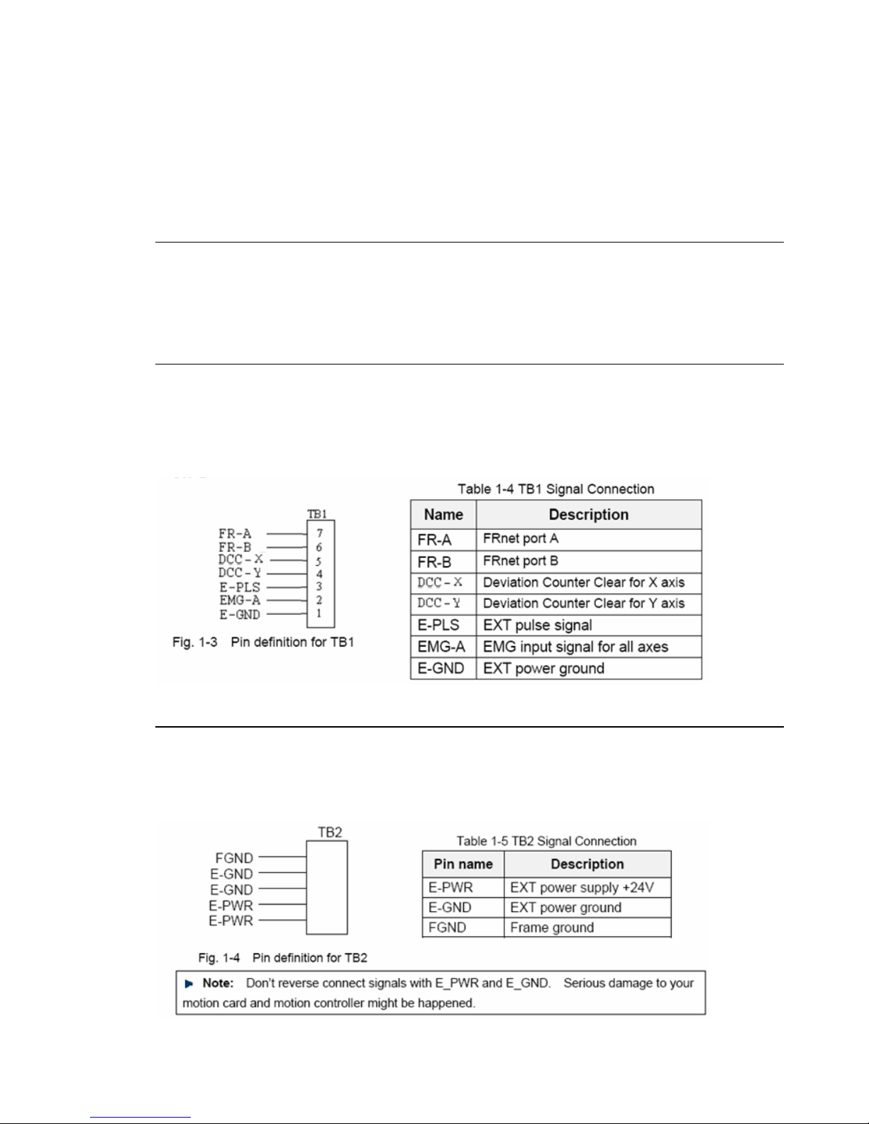
TB1
The connector TB1 is 7-pin connector that enables you to connect to the signals of your motor
drivers. Fig.1-3 shows the pin assignment for the 7-pin connector on the DN-8468M, and the
Table 1-4 shows its I/O connector signal description.
TB2
The connector TB2 is 5-pin connector that enables you to connect to the signals of your motor
drivers. Fig.1-4 shows the pin assignment for the 5-pin connector on the DN-8468M, and the
Table 1-5 shows its I/O connector signal description.
Page 71

http://www.icpdas.com I8094A &I8094HGetting Started manualVer 1.3-- 71
CN-XA, CN-YA, CN-ZA, CN-UA (CNA connector for each AXIS )
The connectors CN-XA, CN-YA, CN-ZA, and CN-UA are 20-pin connectors that enable you to
connect to the CNA connector of Mitsubishi motor drivers. Fig.1-5 shows the pin assignment for
the 20-pin connector on the DN-8468M, and the Table 1-6 shows its I/O connector signal
description.
Table 1-6 CNA Signal Connection
Fig. 1-5 Pin definition for CN-XA,
CN-YA, CN-ZA, CN-UA
Page 72

http://www.icpdas.com I8094A &I8094HGetting Started manualVer 1.3-- 72
CN-XB, CN-YB, CN-ZB, CN-UB (CNB connector for each AXIS )
The connectors CN-XB, CN-YB, CN-ZB, and CN-UB are 20-pin connectors that enable you to
connect to the CNB connector of your motor drivers. Fig.1-6 shows the pin assignment for the
20-pin connector on the DN-8468M, and the Table 1-7 shows its I/O connector signal description.
Table 1-7 CNB Signal Connection
Fig. 1-6 Pin definition for CN-XB, CN-YB
CN-ZB, CN-UB
Page 73

http://www.icpdas.com I8094A &I8094HGetting Started manualVer 1.3-- 73
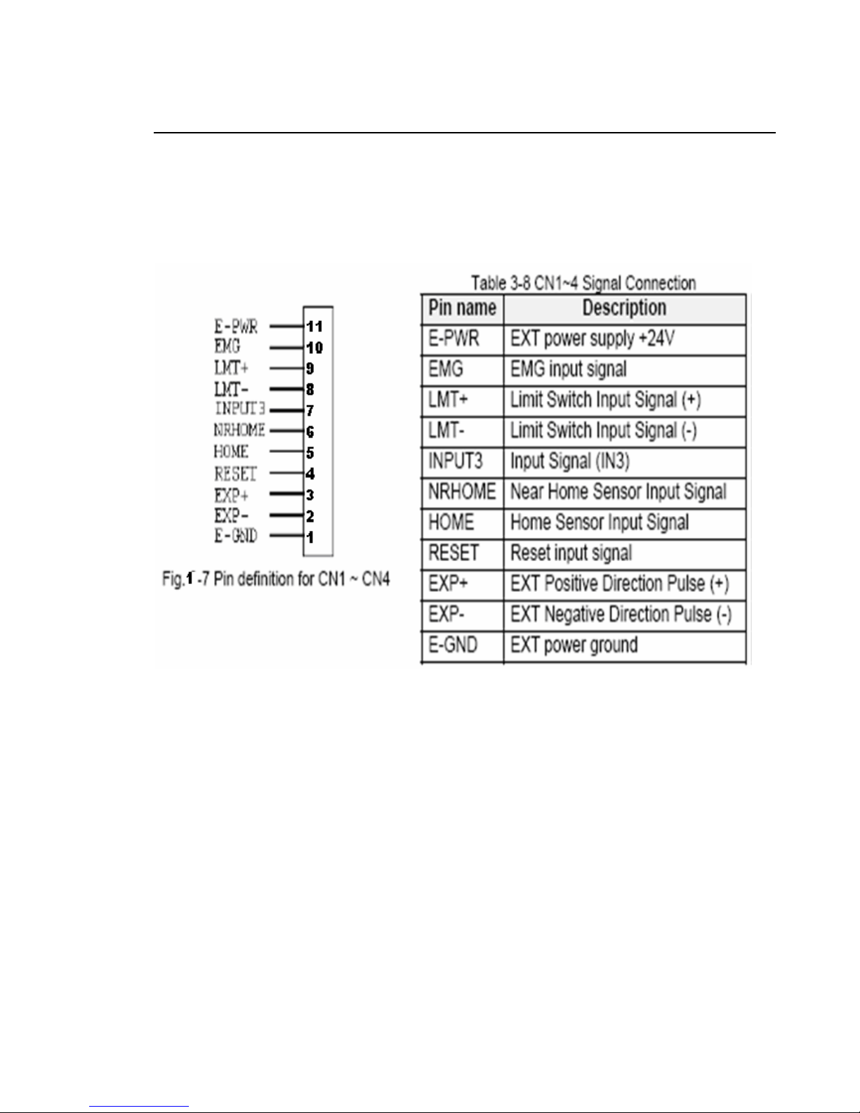
CN1~CN4 (The I/O signals of the X, Y, Z, U AXIS )
The connectors CN1~CN4 are 11-pin connectors that enable you to connect to the signals of
your motor drivers. Fig.1-7 shows the pin assignment for the 20-pin connector on the DN-8468M,
and the Table 1-8 shows its I/O connector signal description.
Table 1-8 CN1~4 Signal Connection
Name Number Description
ERC 12 Error Count Clear
EXT_PWR 11 EXT POWER 24V
EMG 10 Emergent Stop
LMT+ 9 Limit switch Input
Signal(+)
LMT- 8 Limit switch Input Signal(-)
INPUT3 7 Input Signal (IN3)
NRHOME 6 Near HOME Sensor Input
Signal
HOME 5 HOME Sensor Input
Signal
RESET 4 RESET Input Signal
EXP+ 3 EXT Positive Direction
Pulse(+)
EXP- 2 EXT Positive Direction
Pulse(-)
EXT_GND 1 EXT POWER Ground
Fig 1-7 Pin definition for CN1~ CN4
Page 74

http://www.icpdas.com I8094A &I8094HGetting Started manual Ver 1.3-- 74
CN5~CN8 (The I/O signals of the X, Y, Z, U AXIS )
The connectors CN5~CN8 are 15-pin connectors that enable users to connect the signals to
external motor drivers. Fig.1-8 shows the pin assignment for the 15-pin connector on the
DN-8468M, and the Table 1-9 shows its I/O connector signal description.
Table 1-9 CN5~8
Fig. 1-8 Pin definition for CN5~CN8
Page 75

http://www.icpdas.com I8094A &I8094HGetting Started manual Ver 1.3-- 75
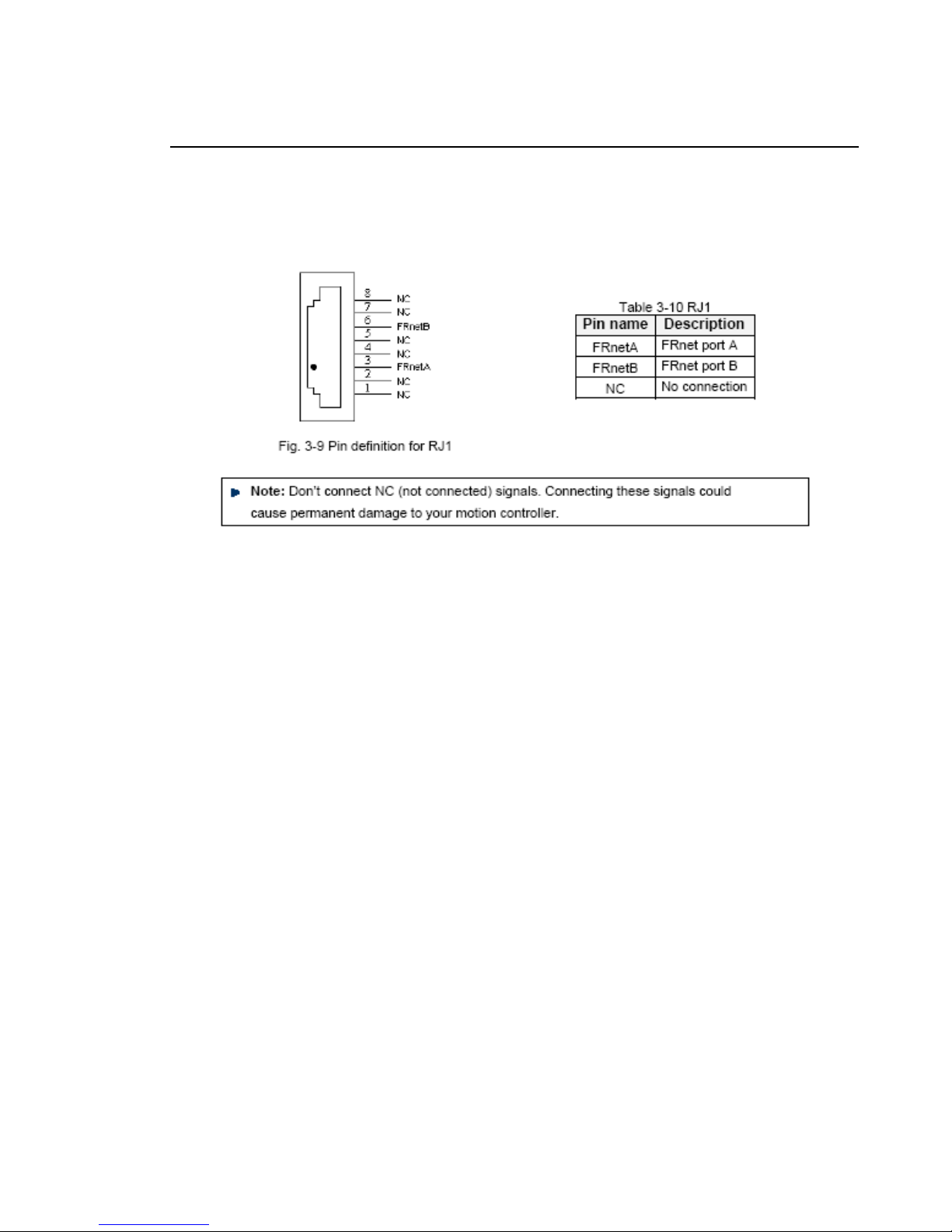
RJ1 (The I/O signals of the FRnet)
The connectors RJ1 is an 8-pin RJ45 connector that enable you to connect to the signals of
FRnet. Fig.1-9 shows the pin assignment for the 8-pin connector on the DN-8468M, and the
Table 1-10 shows its I/O connector signal description.
Fig. 1-9 Pin definition for RJ1
Page 76

http://www.icpdas.com I8094A &I8094HGetting Started manual Ver 1.3-- 76
B.1.3 Jumper and Switch Settings
JP5
Jumper 5 controls the EMG-A signal of the TB1 connector. The following diagram is shown the
selection condition of the jumper 5.
Fig. 1-10 Jumper 5 setting
JP1, JP2
The encoder signals of axis X and axis Y can be chosen from servo driver encoder or external
encoder. Fig. 1-11 shows that the encoder signals are selected from servo driver encoder. In
meantime, Fig. 1-12 shows that the encoder signals are selected from external encoder.
Fig. 1-11 Primary encoder signals setting
Fig. 1-12 External encoder signals setting
Page 77

http://www.icpdas.com I8094A &I8094HGetting Started manual Ver 1.3-- 77
EMG SW
The emergency stop signal for each servo ampilfier can be selected from EMG SW. The
number 1, 2 , 3, 4 on EMG SW are denoted as axis X, Y, Z, U, respectively. Fig. 1-13 is the
default setting to connect the EMG singals to GND. The EMG signals from CN1 ~ CN4 will not
take effect. If the switch is disconnected as shown in Fig. 1-14, the emergency stop signals can
be controlled from EMG signals in CN1 ~ CN4.
Fig. 1-13 EMG SW setting for normally GND (Default setting)
Fig. 1-14 EMG SW setting for user controlled signals.
Page 78

http://www.icpdas.com I8094A &I8094HGetting Started manual Ver 1.3-- 78
B.2 DN-8468P Daughter Board
The DN-8468P is the daughter board for Panasonic A4 Series Ampilifier. It has 4-axis I/O
signals.
B.2.1 Board Layout for DN-8468P
TB1
RJ1
JP1 JP2
CNXCNZ
CN1CN7 CN3
CNYCNU
CN6CN2CN8 CN4
CON1
68 PIN SCSI
EMG
SW
TB2
JP5
JP4 JP3
X Y
Z U
DN-8468P
107mm
162mm
CN5
Fig. B2-1 Board layout for the DN-8468P
Page 79

http://www.icpdas.com I8094A &I8094HGetting Started manual Ver 1.3-- 79
B.2.2 Signal Connections for DN-8468P
Maintaining signal connections is one of the most important factors in ensuring that your
application system is sending and receiving data correctly.
Pin Assignment for CON1
The I/O connector on the DN-8468P is a 68-pin SCSI II connector that enables you to connect to
the PISO-PS400 motion card. Please refer to the section 2.2.1( page 15).
TB1
The connector TB1 is 7-pin connector that enables you to connect to the signals of your motor
drivers. Fig.1-3 shows the pin assignment for the 7-pin connector on the DN-8468P, and the
Table 1-4 shows its I/O connector signal description.
TB2
The connector TB2 is 5-pin connector that enables you to connect to the signals of your motor
drivers. Fig.1-4 shows the pin assignment for the 5-pin connector on the DN-8468P, and the
Table 1-5 shows its I/O connector signal description.
Page 80

http://www.icpdas.com I8094A &I8094HGetting Started manual Ver 1.3-- 80
CNX, CNY, CNZ, CNU (CN X5 connector for each AXIS in Driver)
The connectors CNX, CNY, CNZ, and CNU are 50-pin connectors that enable you to connect to
the CN X5 connector of Panasonic motor drivers. Fig.1-5 shows the pin assignment for the
50-pin connector on the DN-8468P, and the Table 1-6 shows its I/O connector signal
description.
Page 81
http://www.icpdas.com I8094A &I8094HGetting Started manual Ver 1.3-- 81
CN1~CN4 (The I/O signals of the X, Y, Z, U AXIS )
The connectors CN1~CN4 are 11-pin connectors that enable you to connect to the signals of
your motor drivers. Fig.1-7 shows the pin assignment for the 20-pin connector on the DN-8468P,
and the Table 1-8 shows its I/O connector signal description.
Page 82

http://www.icpdas.com I8094A &I8094HGetting Started manual Ver 1.3-- 82
CN5~CN8 (The I/O signals of the X, Y, Z, U AXIS )
The connectors CN5~CN8 are 15-pin connectors that enable users to connect the signals to
external motor drivers. Fig.1-8 shows the pin assignment for the 15-pin connector on the
DN-8468P, and the Table 1-9 shows its I/O connector signal description.
Note 1: There are two sets encoder signals for X and Y axes. In X axis, one is from CNX
and the other is from CN5. In Y axis, one is from CNY and the other is from CN6.
Users can select encoder signals from JP1 and JP2, respectively.
Note 2: In Z and U axes, only one set of encoder signals is used for each axis. In Z axis, do
not connect CNZ and CN7 at the same time. In U axis, do not connect CNU and
CN8 at the same time.
Note 3 : Don’t connect NC (not connected) signals. Connecting these signals could cause
permanent damage to your motion controller.
Page 83

http://www.icpdas.com I8094A &I8094HGetting Started manual Ver 1.3-- 83
RJ1 (The I/O signals of the FRnet)
The connectors RJ1 is an 8-pin RJ45 connector that enable you to connect to the signals of
FRnet. Fig.1-9 shows the pin assignment for the 8-pin connector on the DN-8468P, and the
Table 1-10 shows its I/O connector signal description.
Fig. 1-9 Pin definition for RJ
Note: Don’t connect NC (not connected) signals. Connecting these signals could
cause permanent damage to your motion controller.
Page 84

http://www.icpdas.com I8094A &I8094HGetting Started manual Ver 1.3-- 84
B.2.3 Jumper and Switch Settings
JP5
Jumper 5 controls the EMG-A signal of the TB1 connector. The following diagram is shown the
selection condition of the jumper 5.
Fig. 1-10 Jumper 5 setting
JP1, JP2
The encoder signals of axis X and axis Y can be chosen from servo driver encoder or external
encoder. Fig. 1-11 shows that the encoder signals are selected from servo driver encoder. In
meantime, Fig. 1-12 shows that the encoder signals are selected from external encoder.
Fig. 1-11 Primary encoder signals setting
Page 85

http://www.icpdas.com I8094A &I8094HGetting Started manual Ver 1.3-- 85
Fig. 1-12 External encoder signals setting
EMG SW
The emergency stop signal for each servo ampilfier can be selected from EMG SW. The
number 1, 2 , 3, 4 on EMG SW are denoted as axis X, Y, Z, U, respectively. Fig. 1-13 is the
default setting to connect the EMG singals to GND. The EMG signals from CN1 ~ CN4 will not
take effect. If the switch is disconnected as shown in Fig. 1-14, the emergency stop signals can
be controlled from EMG signals in CN1 ~ CN4.
Fig. 1-13 EMG SW setting for normally GND (Default setting)
Fig. 1-14 EMG SW setting for user controlled signals.
Page 86

http://www.icpdas.com I8094A &I8094HGetting Started manual Ver 1.3-- 86
B.3 DN-8486Y Daughter Board
The DN-8468Y is the daughter board for Yaskawa Ampilifier. It has 4-axis I/O signals.
B.3.1 Board Layout for DN-8468Y
TB1
RJ1
JP1 JP2
CNXCNZ
CN1CN7 CN3
CNYCNU
CN6CN2CN8 CN4
CON1
68 PIN SCSI
EMG
SW
TB2
JP5
JP4 JP3
X Y
Z U
DN-8468Y
107mm
162mm
CN5
Fig. 3-1 Board layout for the DN-8468Y
Page 87

http://www.icpdas.com I8094A &I8094HGetting Started manual Ver 1.3-- 87
B.3.2 Signal Connections for DN-8468Y
Maintaining signal connections is one of the most important factors in ensuring that your
application system is sending and receiving data correctly.
Pin Assignment for CON1
The I/O connector on the DN-8468Y is a 68-pin SCSI II connector that enables you to connect to
the PISO-PS400 motion card. Please refer to the section 2.2.1( page 15).
TB1
The connector TB1 is 7-pin connector that enables you to connect to the signals of your motor
drivers. Fig.3-3 shows the pin assignment for the 7-pin connector on the DN-8468Y, and the
Table 3-4 shows its I/O connector signal description.
TB2
The connector TB2 is 5-pin connector that enables you to connect to the signals of your motor
drivers. Fig.3-4 shows the pin assignment for the 5-pin connector on the DN-8468Y, and the
Table 3-5 shows its I/O connector signal description.
Page 88

http://www.icpdas.com I8094A &I8094HGetting Started manual Ver 1.3-- 88
CNX, CNY, CNZ, CNU (CN X5 connector for each AXIS in Driver)
The connectors CNX, CNY, CNZ, and CNU are 50-pin connectors that enable you to connect to
the CN X5 connector of Panasonic motor drivers. Fig.3-5 shows the pin assignment for the
50-pin connector on the DN-8468Y, and the Table 3-6 shows its I/O connector signal description.
Page 89
http://www.icpdas.com I8094A &I8094HGetting Started manual Ver 1.3-- 89
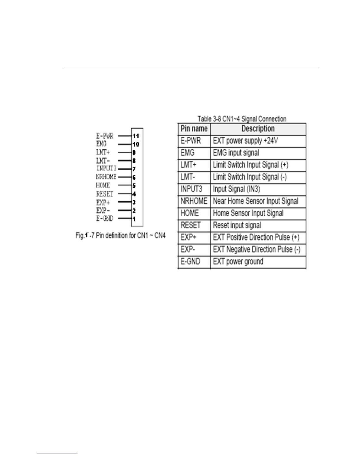
CN1~CN4 (The I/O signals of the X, Y, Z, U AXIS )
The connectors CN1~CN4 are 11-pin connectors that enable you to connect to the signals of
your motor drivers. Fig.3-7 shows the pin assignment for the 20-pin connector on the DN-8468Y,
and the Table 3-8 shows its I/O connector signal description.
Page 90

http://www.icpdas.com I8094A &I8094HGetting Started manual Ver 1.3-- 90
CN5~CN8 (The I/O signals of the X, Y, Z, U AXIS )
The connectors CN5~CN8 are 15-pin connectors that enable users to connect the signals to
external motor drivers. Fig.3-8 shows the pin assignment for the 15-pin connector on the
DN-8468Y, and the Table 3-9 shows its I/O connector signal description.
Page 91
http://www.icpdas.com I8094A &I8094HGetting Started manual Ver 1.3-- 91
RJ1 (The I/O signals of the FRnet)
The connectors RJ1 is an 8-pin RJ45 connector that enable you to connect to the signals of
FRnet. Fig.3-9 shows the pin assignment for the 8-pin connector on the DN-8468Y, and the
Table 3-10 shows its I/O connector signal description.
Page 92

http://www.icpdas.com I8094A &I8094HGetting Started manual Ver 1.3-- 92
B.3.3 Jumper and Switch Settings
JP5
Jumper 5 controls the EMG-A signal of the TB1 connector. The following diagram is shown the
selection condition of the jumper 5.
Fig. 3-10 Jumper 5 setting
JP1, JP2
The encoder signals of axis X and axis Y can be chosen from servo driver encoder or external
encoder. Fig. 3-11 shows that the encoder signals are selected from servo driver encoder. In
meantime, Fig. 3-12 shows that the encoder signals are selected from external encoder.
Fig. 3-11 Primary encoder signals setting
Fig. 3-12 External encoder signals setting
Page 93

http://www.icpdas.com I8094A &I8094HGetting Started manual Ver 1.3-- 93
EMG SW
The emergency stop signal for each servo ampilfier can be selected from EMG SW. The
number 1, 2 , 3, 4 on EMG SW are denoted as axis X, Y, Z, U, respectively. Fig. 3-13 is the
default setting to connect the EMG singals to GND. The EMG signals from CN1 ~ CN4 will not
take effect. If the switch is disconnected as shown in Fig. 3-14, the emergency stop signals can
be controlled from EMG signals in CN1 ~ CN4.
Fig. 3-13 EMG SW setting for normally GND (Default setting)
Fig. 3-14 EMG SW setting for user controlled signals.
Page 94
http://www.icpdas.com I8094A &I8094HGetting Started manual Ver 1.3-- 94
B.4 DN-8468D Daughter Board
The DN-8468D is the daughter board for Delta ASDA-A Series Ampilifier. It has 4-axis I/O
signals.
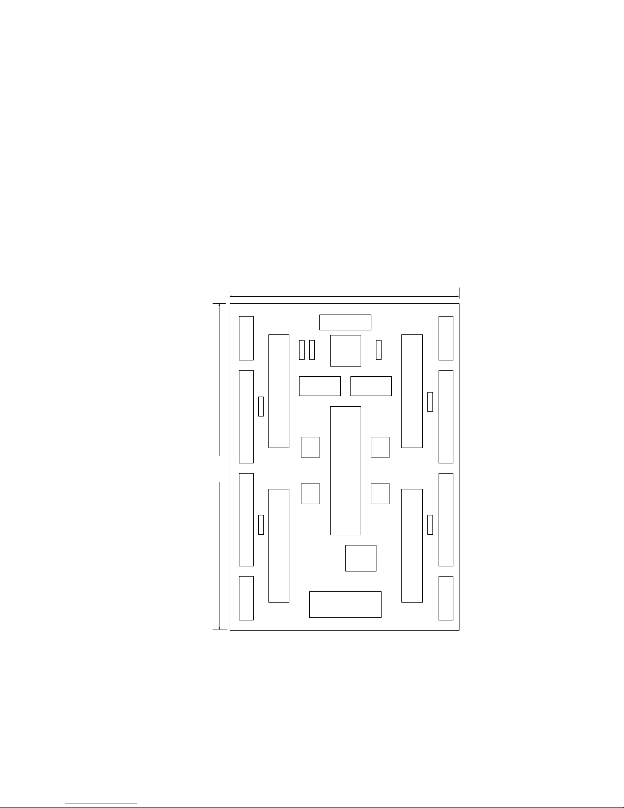
B.4.1 Board Layout for DN-8468D
TB1
RJ1
JP1 JP2
CNXCNZ
CN1CN7 CN3
CNYCNU
CN6CN2CN8 CN4
CON1
68 PIN SCSI
EMG
SW
TB2
JP5
JP4 JP3
X Y
Z U
DN-8468D
107mm
162mm
CN5
JP10
JP11
JP12
JP13
Fig. 3-1 Board layout for the DN-8468D
Page 95

http://www.icpdas.com I8094A &I8094HGetting Started manual Ver 1.3-- 95
B.4.2 Signal Connections for DN-8468D
Maintaining signal connections is one of the most important factors in ensuring that your
application system is sending and receiving data correctly.
Pin Assignment for CON1
The I/O connector on the DN-8468D is a 68-pin SCSI II connector that enables you to connect to
the I-8094 motion card. Fig. 3-2 shows the pin assignment for the 68-pin I/O connector on the
DN-8468D (or on the I-8094), and refer to Table 3-2, 3-3 for description of each motion I/O signal.
Fig. 3-2 I/O connector pin assignment for the CON1
Page 96

http://www.icpdas.com I8094A &I8094HGetting Started manual Ver 1.3-- 96
Table 3-2 DN-8468D I/O connector signal description (part 1)
Pin name Pin number Description
XECA 1 Encoder A-phase signal for X axis
YECA 36 Encoder A-phase signal for Y axis
ZECA 33 Encoder A-phase signal for Z axis
UECA 68 Encoder A-phase signal for U axis
XECB 2 Encoder B-Phase signal for X axis
YECB 37 Encoder B-Phase signal for Y axis
ZECB 32 Encoder B-Phase signal for Z axis
UECB 67 Encoder B-Phase signal for U axis
XINPOS 3 In-position signal for X axis
YINPOS 38 In-position signal for Y axis
ZINPOS 31 In-position signal for Z axis
UINPOS 66 In-position signal for U axis
XALARM 4 Alarm signal for X axis
YALARM 39 Alarm signal for Y axis
ZALARM 30 Alarm signal for Z axis
UALARM 65 Alarm signal for U axis
XLMTP 5 Limit switch input signal (+) for X axis
YLMTP 40 Limit switch input signal (+) for Y axis
ZLMTP 29 Limit switch input signal (+) for Z axis
ULMTP 64 Limit switch input signal (+) for U axis
XLMTM 6 Limit switch input signal (-) for X axis
YLMTM 41 Limit switch input signal (-) for Y axis
ZLMTM 28 Limit switch input signal (-) for Z axis
ULMTM 63 Limit switch input signal (-) for U axis
XIN3 7 Input 3 signal for X axis
YIN3 42 Input 3 signal for Y axis
ZIN3 27 Input 3 signal for Z axis
UIN3 62 Input 3 signal for U axis
XIN2 8 Input 2 signal for X axis
XIN2 43 Input 2 signal for Y axis
XIN2 26 Input 2 signal for Z axis
XIN2 61 Input 2 signal for U axis
XIN1 9 Input 1 signal for X axis
YIN1 44 Input 1 signal for Y axis
ZIN1 25 Input 1 signal for Z axis
UIN1 60 Input 1 signal for U axis
XIN0 10 Input 0 signal for X axis
YIN0 45 Input 0 signal for Y axis
ZIN0 24 Input 0 signal for Z axis
UIN0 59 Input 0 signal for U axis
Page 97

http://www.icpdas.com I8094A &I8094HGetting Started manual Ver 1.3-- 97
Table 3-3 DN-8468D I/O connector signal description (part 2)
Pin name Pin number Description
XEXPP 11 EXT pulsar input signal (+) for X axis
YEXPP 46 EXT pulsar input signal (+) for Y axis
ZEXPP 23 EXT pulsar input signal (+) for Z axis
UEXPP 58 EXT pulsar input signal (+) for U axis
XEXPM 12 EXT pulsar input signal (-) for X axis
YEXPM 47 EXT pulsar input signal (-) for Y axis
ZEXPM 22 EXT pulsar input signal (-) for Z axis
UEXPM 57 EXT pulsar input signal (-) for U axis
XDRIVE 13 Driver enable signal for X axis
YDRIVE 48 Driver enable signal for Y axis
ZDRIVE 21 Driver enable signal for Z axis
UDRIVE 56 Driver enable signal for U axis
XPP 14 Driving pulsar signal (+) for X axis
YPP 49 Driving pulsar signal (+) for Y axis
ZPP 20 Driving pulsar signal (+) for Z axis
UPP 55 Driving pulsar signal (+) for U axis
XPM 15 Driving pulsar signal (+) for X axis
YPM 50 Driving pulsar signal (+) for Y axis
ZPM 19 Driving pulsar signal (+) for Z axis
UPM 54 Driving pulsar signal (+) for U axis
XOUT1 16 Output 1 signal for X axis
YOUT1 48 Output 1 signal for Y axis
ZOUT1 21 Output 1 signal for Z axis
UOUT1 56 Output 1 signal for U axis
EXPLSN1 17 EXT pulse input signal for interpolation
EMGN1 52 Emergency stop input signal
FRnetA 16 FRnet port A
FRnetB 18 FRnet port B
XDCC 51 Deviation Counter Clear for X axis
YDCC 53 Deviation Counter Clear for Y axis
GND 34 Ground
VCC 35 External power (12~24V)
Page 98

http://www.icpdas.com I8094A &I8094HGetting Started manual Ver 1.3-- 98
TB1
The connector TB1 is 7-pin connector that enables you to connect to the signals of your motor
drivers. Fig.3-3 shows the pin assignment for the 7-pin connector on the DN-8468D, and the
Table 3-4 shows its I/O connector signal description.
TB2
The connector TB2 is 5-pin connector that enables you to connect to the signals of your motor
drivers. Fig.3-4 shows the pin assignment for the 5-pin connector on the DN-8468D, and the
Table 3-5 shows its I/O connector signal description.
Page 99

http://www.icpdas.com I8094A &I8094HGetting Started manual Ver 1.3-- 99
CNX, CNY, CNZ, CNU (CN 1 connector for each AXIS in Driver)
The connectors CNX, CNY, CNZ, and CNU are 50-pin connectors that enable you to connect to
the CN1 connector of Delta ASDA-A series motor drivers. Fig.3-5 shows the pin assignment for
the 50-pin connector on the DN-8468D, and the Table 3-6 shows its I/O connector signal
description.
Page 100
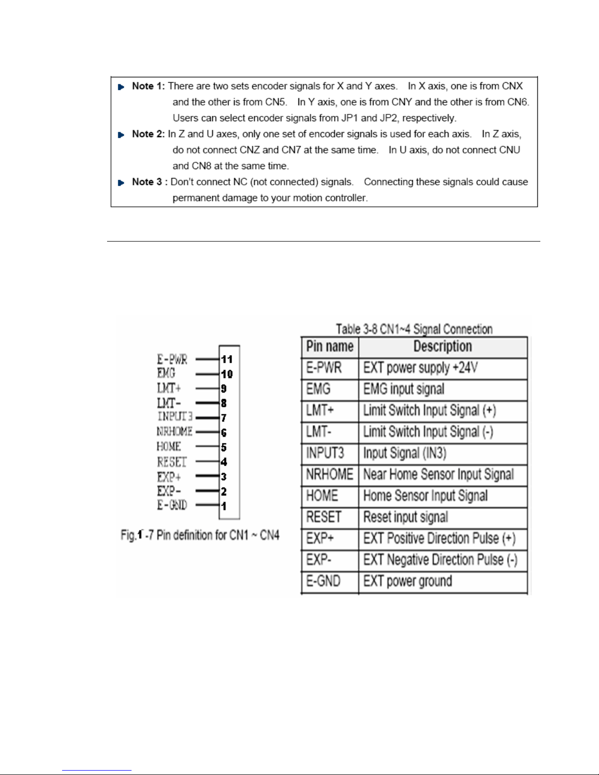
http://www.icpdas.com I8094A &I8094HGetting Started manual Ver 1.3-- 100
CN1~CN4 (The I/O signals of the X, Y, Z, U AXIS )
The connectors CN1~CN4 are 11-pin connectors that enable you to connect to the signals of
your motor drivers. Fig.3-7 shows the pin assignment for the 20-pin connector on the DN-8468D,
and the Table 3-8 shows its I/O connector signal description.
 Loading...