

Page 1

I-8092F Getting Started Manual
(Version 1.0)
Hardware & Software & Application
Using I-8092F PAC Motion Control Module
http://www.icpdas.com I8092F Getting Started Manual for XPAC_CE
1
Page 2

Warranty
All products manufactured by ICPDAS Inc. are warranted against defective
materials for a period of one year from the date of delivery to the original
purchaser.
Warning
ICPDAS Inc. assumes no liability for damages consequent to the use of this
product. ICPDAS Inc. reserves the right to change this manual at any time
without notice. The information furnished by ICPDAS Inc. is believed to be
accurate and reliable. However, no responsibility is assumed by ICPDAS Inc. for
its use, or for any infringements of patents or other rights of third parties
resulting from its use.
Copyright
Copyright 2005-2015 by ICPDAS Inc., LTD. All rights reserved worldwide.
Trademark
The names used for identification only maybe registered trademarks of
their respective companies.
License
The user can use, modify and backup this software on a single machine.
The user may not reproduce, transfer or distribute this software, or any copy, in
whole or in part.
http://www.icpdas.com I8092F Getting Started Manual for XPAC_CE
2
Page 3

Contents of I8092F
1 INTRODUCTION...............................................................5
1.1 Introduction................................................................................................5
1.2 Hardware Specification.............................................................................6
1.2.1 Main Specification.................................................................................... 6
1.2.2 Interpolation Function............................................................................... 6
1.2.3 Pulse Output............................................................................................. 6
1.2.4 Encoder Input........................................................................................... 7
1.2.5 Position counter........................................................................................ 7
1.2.6 Servo Motor Input Signal.......................................................................... 7
1.2.7 Limit Switch Input Signal .......................................................................... 7
1.2.8 Other Input Signals................................................................................... 7
1.2.9 Emergency Stop Signal Input................................................................... 8
1.2.10 General Output Signal............................................................................ 8
1.2.11 Integral Input Signal Filters..................................................................... 8
1.2.12 Software Limit......................................................................................... 8
1.2.13 Manual Pulse Generator ........................................................................ 8
1.2.14 LED for Module status............................................................................ 8
1.2.15 FRnet ..................................................................................................... 8
1.3 Environment...............................................................................................9
1.4 Ordering Information................................................................................9
2 HARDWARE INSTALLATION......................................10
2.1 Checking Package and Installation........................................................10
2.1.1 Checking package.................................................................................. 10
2.1.2 Installation.............................................................................................. 10
2.2 DN-8237-GB Daughter Board................................................................ 11
2.2.1 Board Layout for DN-8237-GB................................................................11
2.2.2 Signal Connections for DN-8237-GB...................................................... 12
2.2.3 Jumper and Switch Settings................................................................... 16
2.3 Input/Output Connections......................................................................19
2.3.1 Pulse output signals............................................................................... 19
2.3.2 Connection for Limit switch Signal.......................................................... 21
2.3.3 General Purpose Input Signals(nINPOS,nALARM)................................ 21
2.3.4 Encoder Signals..................................................................................... 22
2.3.5 Emergency Stop Signal.......................................................................... 22
http://www.icpdas.com I8092F Getting Started Manual for XPAC_CE
3
Page 4

2.3.6 Manual Pulse Generator Input Signal (EXP+,EXP-) ............................... 23
2.3.7 General Purpose Output signals(Servo On/Off)..................................... 23
2.4 Connection Example for Motor Driver .................................................24
3 SOFTWARE DEVELOPMENT OVERVIEW...............25
3.1 Software development Overview............................................................25
3.2 PAC Software Installation.......................................................................27
3.2.1 Install i-8092F software in XPAC_CE..................................................... 27
3.2.2 Install i-8092F software into WinPAC ..................................................... 29
3.2.3 Install i-8092F software into XPAC_XPe ................................................ 31
3.3 Motion Configuration Tool .....................................................................32
3.4 i8092 EzGo................................................................................................34
3.4.1 Configuration Dialog............................................................................... 35
3.4.2 Basic Operation Dialog........................................................................... 38
3.4.3 Interpolation Dialog ................................................................................ 40
3.5 EzFRnet ....................................................................................................42
3.6 Install Software Development Package .................................................43
3.6.1 Installs SDK on WinPAC/XPAC_CE ....................................................... 43
3.6.2 Installs SDK on XPAC_XPe.................................................................... 45
APPENDIX A OTHER TERMINAL BOARDS................46
A.1 DN-8237-DB Daughter Board................................................................46
A.1.1 Board Layout for DN-8237-DB............................................................... 46
A.1.2 Signal Connections for DN-8237-DB ..................................................... 47
A.1.3 Jumper and Switch Settings................................................................... 52
A.2 DN-8237-MB Daughter Board...............................................................55
A.2.1 Board Layout for DN-8237-MB............................................................... 55
A.2.2 Signal Connections for DN-8237-MB..................................................... 56
A2.3 Jumper and Switch Settings.................................................................... 63
A.3 DN-8237-PB Daughter Board................................................................65
A.3.1 Board Layout for DN-8237-PB............................................................... 65
A.3.2 Signal Connections for DN-8237-PB...................................................... 66
A.3.3 Jumper and Switch Settings................................................................... 71
A.4 DN-8237-YB Daughter Board................................................................73
A.4.1 Board Layout for DN-8237-YB............................................................... 73
A.4.2 Signal Connections for DN-8237-YB...................................................... 74
A.4.3 Jumper and Switch Settings................................................................... 79
http://www.icpdas.com I8092F Getting Started Manual for XPAC_CE
4
Page 5

1 INTRODUCTION
1.1 Introduction
The I-8092F are the 2-axis pulse-type stepping/servo motor motion control
module that can be used on any of the ICPDAS WinPAC/XPAC_XPe/XPAC_CE
(XPAC Compact Edition) series controllers, and is suitable for general-purpose
motion application. These modules contain a high-performance motion ASIC.
Apart from a wide speed range, these intelligent motion controllers have a
variety of motion control functions built in, such as 2-axis linear interpolation,
2-axis circular interpolation, T/S-curve acceleration/ deceleration, automatic
homing, and others. Besides, it is a module that has full functions of I-8092F
plus one port of FRnet. The FRnet port allows this module to expand its fast
remote I/O easily. This two-wired FRnet can automatically scan its 128 DI and
128 DO with a period of 0.72/2.88ms. In addition, most of the I-8092F motion
control functions are performed with little load on the processor. While driving
the motors, the motion status, and the other I/O status on the
WinPAC/XPAC_XPe/XPAC_CE controllers, can still be monitored. As a result
of the low CPU loading requirements of I-8092F, one or more motion modules
may be used on a single WinPAC/XPAC_XPe/XPAC_CE controllers. ICPDAS
also has provided a wide range of functions and examples to reduce the need
for programming by user, making it a highly cost-effective solution for machine
makers.
http://www.icpdas.com I8092F Getting Started Manual for XPAC_CE
5
Page 6

1.2 Hardware Specification
1.2.1 Main Specification
ASIC Chip MCX312
Number of controllable 2-axis, Pulse output (stepping & servo
motor)
Up to 4M PPS pulse output
1.2.2 Interpolation Function
2-axis linear interpolation
Interpolation range −8,388,607 ~ +8,388607
Vectors speed of interpolation 1 PPS ~ 4M PPS
Precision of interpolation ± 0.5 LSB
Circular interpolation
Interpolation range −8,388,607 ~ +8,388607
Vectors Speed of interpolation 1 PPS ~ 4M PPS
Bit interpolation
Vectors Speed of interpolation 1 PPS ~ 4M PPS(Dependent on
CPIU
data writing time)
Relative interpolation function
Fixed vectors speed
Continuous interpolation
1.2.3 Pulse Output
Output speed range 1 PPS ~ 4 MPPS
Output precision ± 0.1%
Jerk range of S-curve 954 ~ 62.5 x 10^6 PPS/S^2
477 x 10^3 ~ 31.25 x 10^9 PPS/S^2
Acceleration/deceleration range 125 ~ 1 x 10^6 PPS/S
62.5×10^3 ~ 500 x 10^6 PPS/S
Speed precision 1 PPS ~ 500PPS( Depend on the
max.speed)
Output numbers 0 ~ 4,294,967,295 / unlimited
Velocity profiles mode:
Fixed
http://www.icpdas.com I8092F Getting Started Manual for XPAC_CE
6
Page 7

Symmetrical & Asymmetrical Trapezoidal velocity profile
Symmetrical & Asymmetrical S-curve velocity profile
Acceleration & Deceleration mode
Auto
By user define
Position & Speed change on the fly
Fixed pulse output by Trapezoidal and S-curve velocity profile
Pulse output option: CW/CCW, PULSE/DIR
Programmable logic level (Rising Edge/ Falling Edge)
1.2.4 Encoder Input
Encoder option: A/B phase, Up/Down
Programmable A/B phase mode: 1, 1/2, and 1/4 A/B phase
Programmable direction of counter
1.2.5 Position counter
Command counter range −2,147,483,648 ~ +2,147,483,647
Encoder counter range −2,147,483,648 ~ +2,147,483,647
Programmable ring counter
Programmable direction of counter
Programmable read & write counter
1.2.6 Servo Motor Input Signal
Alarm
Choose IN2: In Position or Servo Ready signal
Choose input signal: Enable/Disable and logical level.
1.2.7 Limit Switch Input Signal
Two-limit switch signal for each axis: +Limit, −Limit
Programmable logic level
Programmable action mode( slow-down stop or immediately stop)
1.2.8 Other Input Signals
IN3 : Digital Input of general purpose.
http://www.icpdas.com I8092F Getting Started Manual for XPAC_CE
7
Page 8

1.2.9 Emergency Stop Signal Input
There is a Emergency stop signal for Each module.
1.2.10 General Output Signal
Capability of configurable nOUT0 of each axes as general purpose DO
signals.
Capability of configurable nOUT1 of each axes as Servo On/Off signal.
1.2.11 Integral Input Signal Filters
The motion module is equipped with an integral type filter in the input
step of each input signal. User can be selected a filter time constant.
1.2.12 Software Limit
There are two software-limit for each axis: -SLimit & + SLimit ( Setting
range : −2,147,483,646 ~ +2,147,483,646)
1.2.13 Manual Pulse Generator
Fixed Pulse Driving Mode (CW/CCW pulse mode)
Continuous Pulse Driving Mode (CW/CCW pulse mode)
Manual pulsar mode(A/B phase pulse mode)
Disable Mode: Disable manual pulse function
1.2.14 LED for Module status
Red LED Power light
Orange LED Servo Alarm
Ex:Misuibishi driver, No Alm: turn Orange LED on
Green LED during Running Motion
1.2.15 FRnet
Connect to the distributed DI/DO module DI max up to 128
DO max up to 128
Read the status of distributed DI
Control the status of distributed DO
Support interrupt and frequence division function
Reset function
http://www.icpdas.com I8092F Getting Started Manual for XPAC_CE
8
Page 9

1.3 Environment
Operating Temp: -20 ~ + 75°C
Storage Temp: -30 ~ +85°C
Operating Humidity: 10 ~ 85%,non-condensing
Storage Humidity: 5 ~ 90%,non-condensing
I/O optically isolated 2500Vrms
External Power supply( Input): 24V DC (connect to terminal board)
1.4 Ordering Information
i8092F 2-axis motion control module
DN-8237GB For general purpose usage
DN-8237DB For Delta ASDA Servo motor
DN-8237MB For Mitsubishi J2 Servo motor
DN-8237PB For Panasonic minas A4 Servo motor
DN-8237YB For Yaskawa Σ-Ⅱ Servo motor
CA-3710DM 37-pin Dsub cable,length:1.0 m
CA-3730DM 37-pin Dsub cable,length:3.0 m
CA3750DM 37-pin Dsub cable,length:5.0 m
4PCA-SCSI20-M1 20-pin SCSI cable, length: 1.0 m
4PCA-SCSI50-D1 50-pin SCSI cable for Delta, length: 1.0 m
4PCA-SCSI50-PY1 50-pin SCSI cable for Panasonic and Yaskawa,
length:
1.0 m
http://www.icpdas.com I8092F Getting Started Manual for XPAC_CE
9
Page 10

2 HARDWARE INSTALLATION
2.1 Checking Package and Installation
2.1.1 Checking package
The i8092F are a 2-axis stepping/servo motor control module that can be
used on any of the ICPDAS WinPAC and XPAC_XPe/XPAC_CE series
controllers.
2.1.2 Installation
Prepare controller
1. Choose a PAC controller of ICPDAS (WinPAC or XPAC_XPe/XPAC_CE
series) and have empty slot.
2. Turn power off
Module Plug in controller and wiring
1. Plug in the i8092F into a empty slot of WinPAC/XPAC_XPE/XPAC_CE .
2. Connect the i8092F with DN-8237 by a CA-3710DM cable, as the below
figure:
Figure. i8092F with PAC controller
http://www.icpdas.com I8092F Getting Started ManualVer.2.3 10
Page 11

2.2 DN-8237-GB Daughter Board
The DN-8237-GB is the daughter board for General Purpose Ampilifiers. It has 2-axis I/O
signals.
2.2.1 Board Layout for DN-8237-GB
107mm
CON4
SW
EMG
JP3
JP4
110mm
CON3
CON1
Y X
37 PIN CONNECTOR
DN-8237-MB
RJ1
JP5
JP1
JP2
CON2
TB1
Fig. 2-1 Board layout for the DN-8237-GB
http://www.icpdas.com I8092F Getting Started ManualVer.2.3 11
Page 12
2.2.2 Signal Connections for DN-8237-GB
Maintaining signal connections is one of the most important factors in ensuring that your
application system is sending and receiving data correctly.
Pin Assignment for CON1
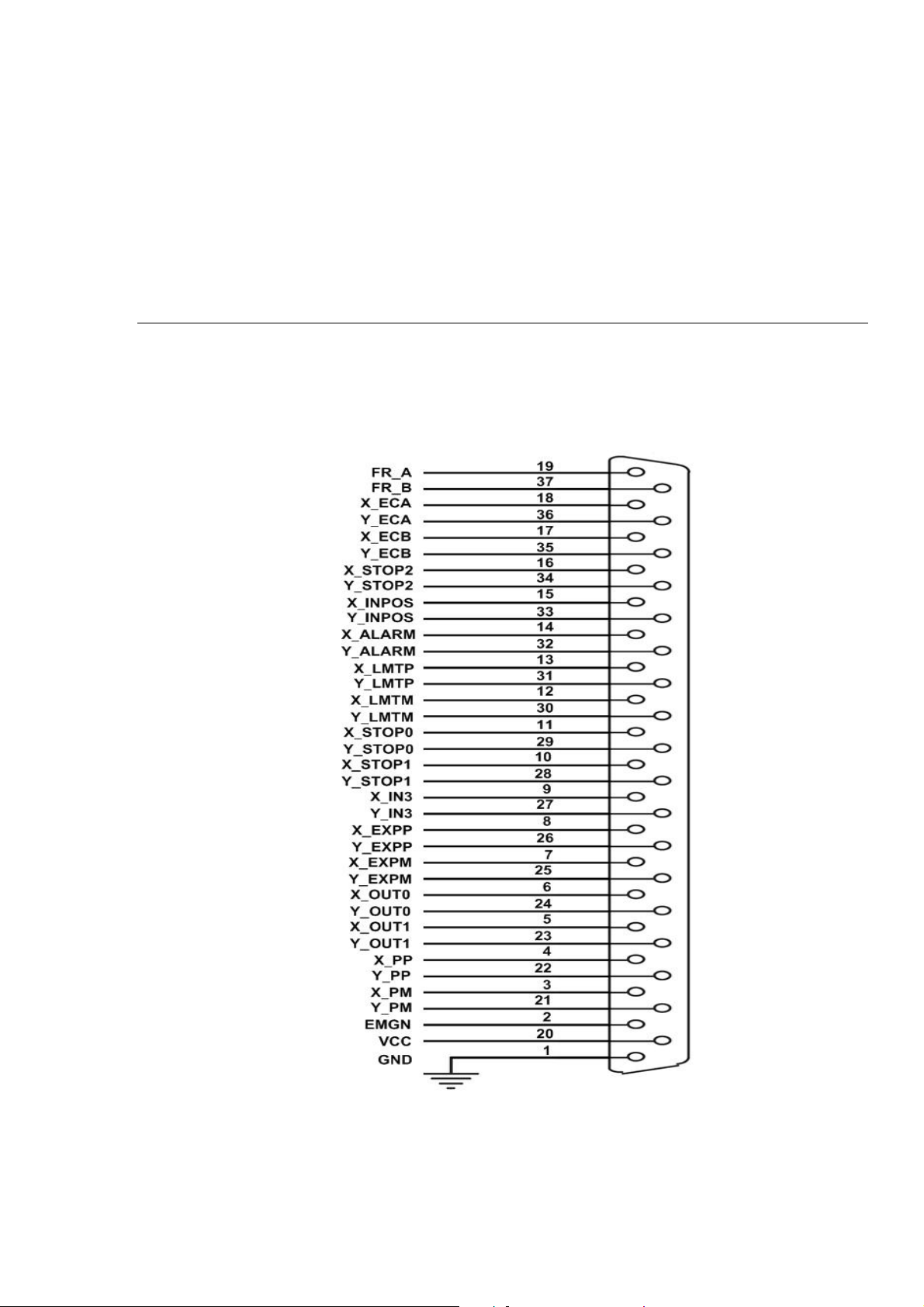
The I/O connector on the DN-8237-GB is a 37-pin connector that enables you to connect to
the PISO-PS200(or I-8092F) motion card. Fig. 2-2 shows the pin assignment for the 37-pin
I/O connector on the DN-8237-GB (or on the motion card), and refer to Table 2-2 for
description of each motion I/O signal.
Fig. 2-2 I/O connector pin assignment for the CON1
http://www.icpdas.com I8092F Getting Started ManualVer.2.3 12
Page 13

Table 2-2 DN-8237-MB CON1 I/O connector signal description
Pin name Pin number Description
FR_A 19 FRnet A-phase signal
FR_B 37 FRnet B-phase signal
X_ECA 18 Encoder A-phase signal for the X axis
Y_ECA 36 Encoder A-phase signal for the Y axis
X_ECB 17 Encoder B-Phase signal for the X axis
Y_ECB 35 Encoder B-Phase signal for the Y axis
X_STOP2 16 Stop 2 signal for the X axis
Y_STOP2 34 Stop 2 signal for the Y axis
X_INPOS 15 In-position signal for the X axis
Y_INPOS 33 In-position signal for the Y axis
X_ALARM 14 Alarm signal for the X axis
Y_ALARM 32 Alarm signal for the Y axis
X_LMTP 13 Limit switch input signal (+) for the X axis
Y_LMTP 31 Limit switch input signal (+) for the Y axis
X_LMTM 12 Limit switch input signal (-) for the X axis
Y_LMTM 30 Limit switch input signal (-) for the Y axis
X_STOP0 11 Stop 0 signal for the X axis
Y_STOP0 29 Stop 0 signal for the Y axis
X_STOP1 10 Stop 1 signal for the X axis
Y_STOP1 28 Stop 1 signal for the Y axis
X_IN3 9 Input 3 signal for the X axis
Y_IN3 27 Input 3 signal for the Y axis
X_EXPP 8
Y_EXPP 26
X_EXPM 7
Y_EXPM 25
X_OUT0 6
Y_OUT0 24
X_OUT1 5
Y_OUT1 23
XPP 4
YPP 22
XPM 3
YPM 21
EMGN 2 Emergency stop input signal
VCC 20 Module power (+5V)
GND 1 Ground
EXT pulsar input signal (+) for the X axis
EXT pulsar input signal (+) for the Y axis
EXT pulsar input signal (-) for the X axis
EXT pulsar input signal (-) for the Y axis
Output 0 signal for the X axis
Output 0 signal for the Y axis
Output 1 signal for the X axis
Output 1 signal for the Y axis
Driving pulsar signal (+) for the X axis
Driving pulsar signal (+) for the Y axis
Driving pulsar signal (+) for the X axis
Driving pulsar signal (+) for the Y axis
http://www.icpdas.com I8092F Getting Started ManualVer.2.3 13
Page 14
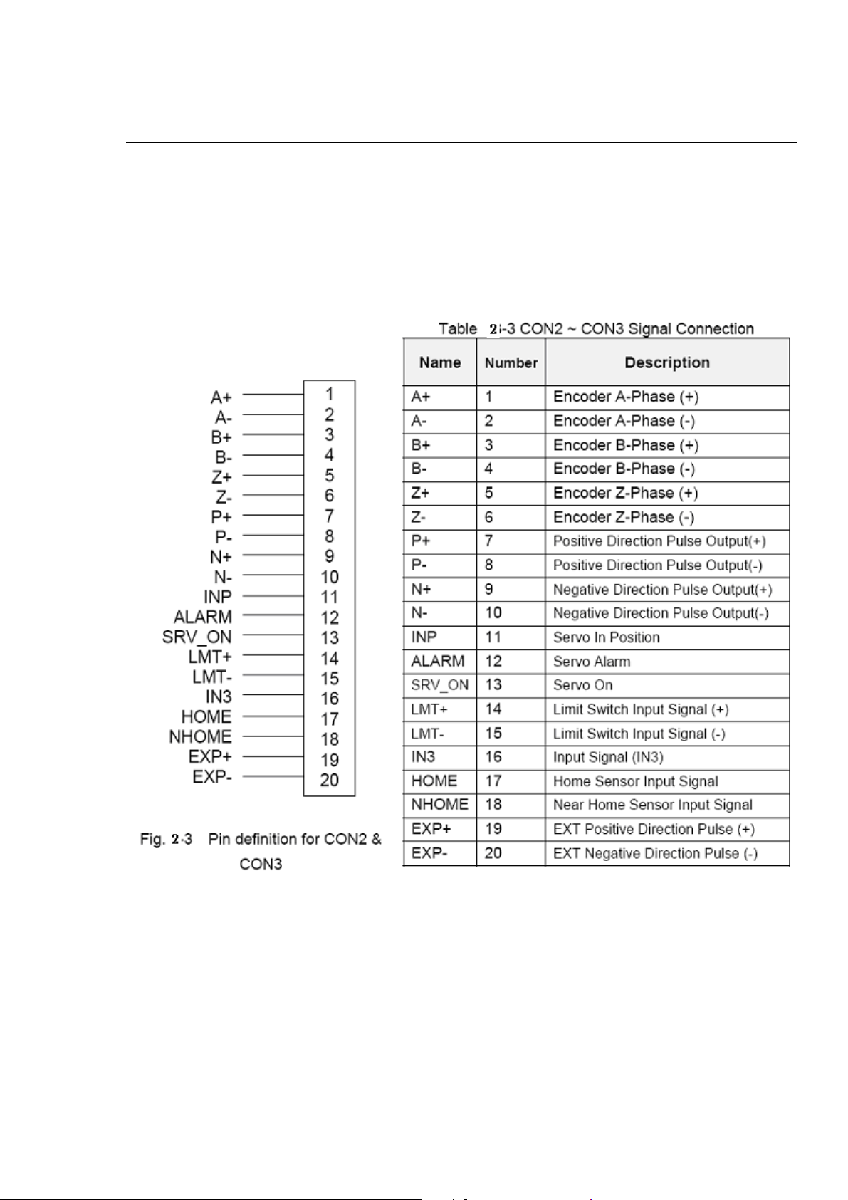
CON2 & CON3 (I/O connector for each AXIS)
The connectors CON2 and CON3 are 20-pin connectors that enable you to connect to the
I/O signals for general purpose motor drivers. Fig.2-3 shows the pin assignment for the
20-pin connector on the DN-8237-GB, and the Table 2-3 shows its I/O connector signal
description.
http://www.icpdas.com I8092F Getting Started ManualVer.2.3 14
Page 15
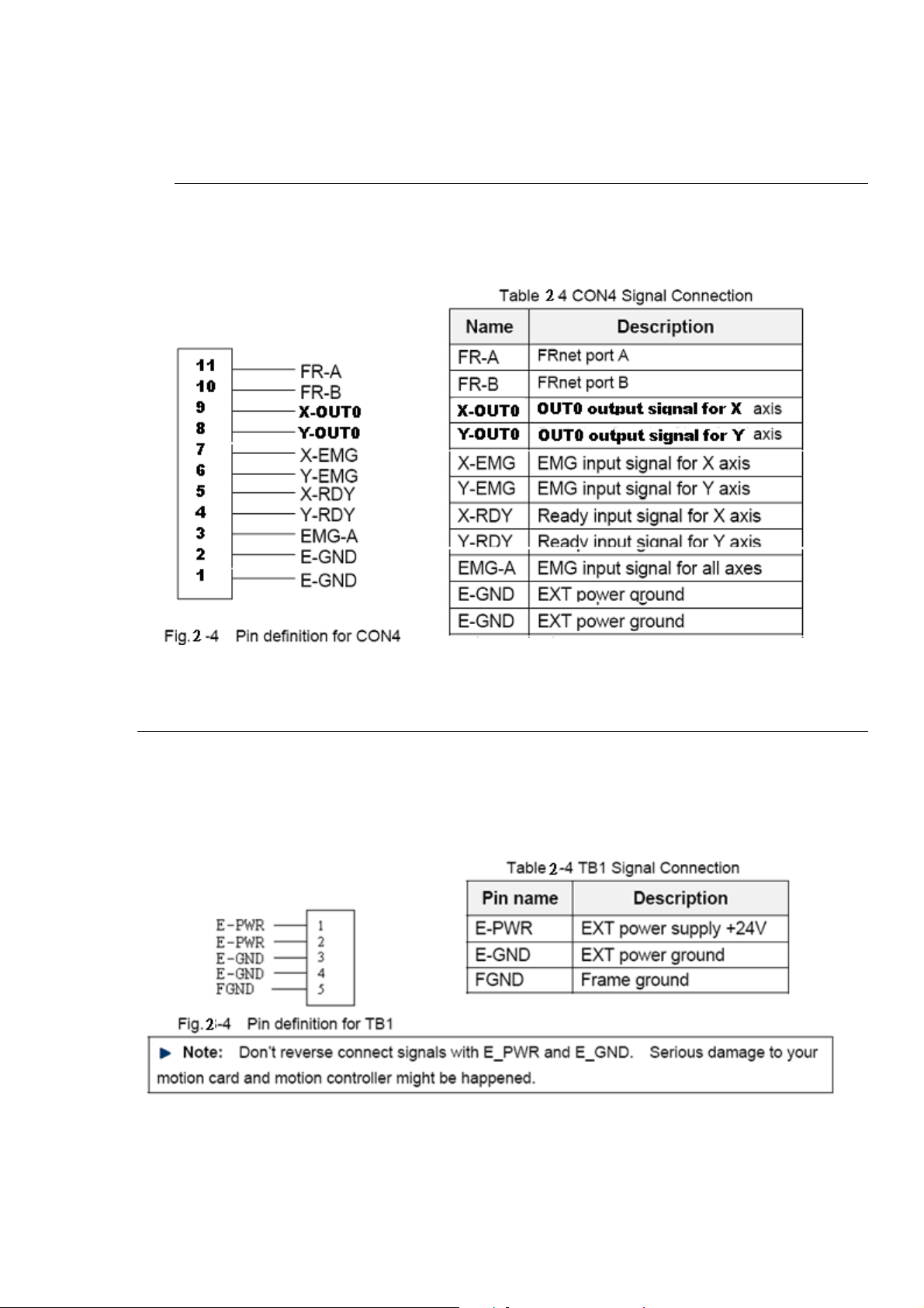
CON4
The connector CON4 is 16-pin connector that enables you to connect to the signals of
your motor drivers. Fig.2-4 shows the pin assignment for the 11-pin connector on the
DN-8237-GB, and the Table 2-4 shows its I/O connector signal description.
TB1
The connector TB1 is 5-pin connector that enables you to connect to the signals of your
motor drivers. Fig.2-4 shows the pin assignment for the 5-pin connector on the
DN-8237-GB, and the Table 2-4 shows its I/O connector signal description.
http://www.icpdas.com I8092F Getting Started ManualVer.2.3 15
Page 16
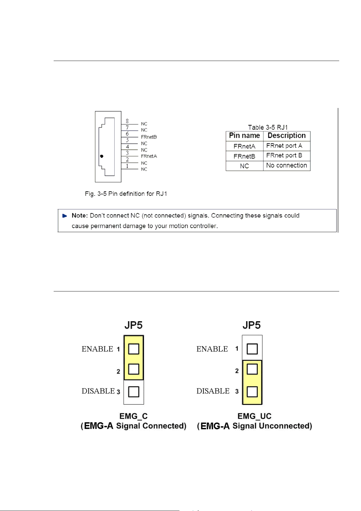
RJ1 (The I/O signals of the FRnet)
The connectors RJ1 is an 8-pin RJ45 connector that enable you to connect to the signals
of FRnet. Fig.3-5 shows the pin assignment for the 8-pin connector on the DN-8237-GB,
and the Table 3-5 shows its I/O connector signal description.
2.2.3 Jumper and Switch Settings
JP5
Jumper 5 controls the EMG-A signal of the CON4 connector. The following diagram is
shown the selection condition of the jumper 5.
Fig. 3-6 Jumper 5 setting
http://www.icpdas.com I8092F Getting Started ManualVer.2.3 16
Page 17
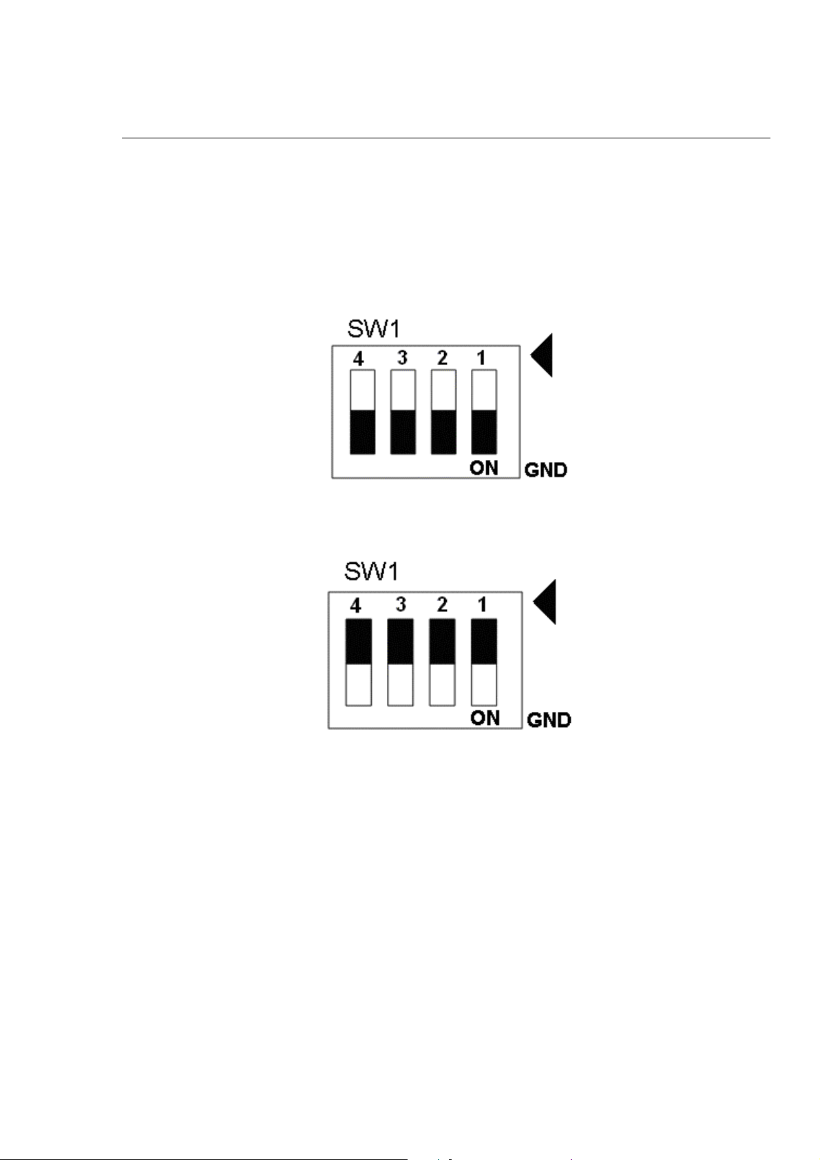
SW 1
The emergency stop signal for each servo ampilfier can be selected from SW1. The
number 1 and 2 on SW1 are denoted as axis X and Y, respectively. The number 3 and 4
on SW1 are reserved for future work. Fig. 3-7 is the default setting to connect the EMG
singals to GND. The X-EMG and Y-EMG signal from CON4 not take effect. If the switch
is disconnected as shown in Fig. 3-8, the emergency stop signals can be controlled from
the X-EMG and Y-EMG signal in CON4.
Fig. 3-7 SW1 setting for normally GND (Default setting)
Fig. 3-8 SW1 setting for user controlled signals.
http://www.icpdas.com I8092F Getting Started ManualVer.2.3 17
Page 18
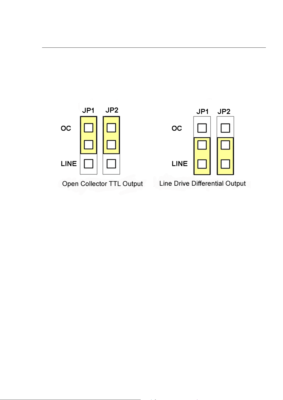
JP1/2 & JP3/4
Jumper 1, 2 controls the XPP, XPM signals of the CON2. The couple of jumpers are
indicated the type of pulse output signal for X axis. However there are the same jumper
settings for Y axis (Jumper 3, 4 for Y axis). The following diagram is shown the selection
condition of the jumper 1, 2.
Fig. 3-9 Jumper 1, 2 setting
http://www.icpdas.com I8092F Getting Started ManualVer.2.3 18
Page 19
2.3 Input/Output Connections
The signal connections of all the I/O signals are described in this chapter. Please
refer the contents of this chapter befor wiring the cable between the i8092F and
the motor drivers.
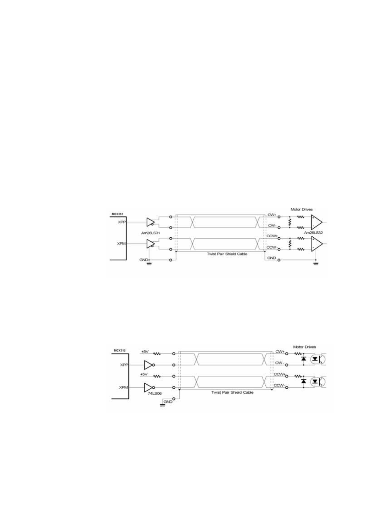
2.3.1 Pulse output signals
There are 2-axis pulse output signals on I8092F, For every axis, two pairs of CW
and CCW signals are used to send the pulse train. The CW and CCW signals can
also be programmed as PULSE and DIR signals pait.
signal, Differential-Type and Open-Collector Type, can be selected from JP2/3 and JP4/5
and are described in section 2.2.2. The following wiring diagram is for the CW and CCW
signals of the 2-axis.
Output to Motor Drivers in Differential Circuit
Two types of the pulse output
Fig. 2.8 Differential-Type pulse output circuit
Open Collector TTL Output
Fig. 2.9 The wiring is open collector output
http://www.icpdas.com I8092F Getting Started ManualVer.2.3 19
Page 20
Example: wiring of pulse signal
Two types of pulse output signal, Differential-Type and Open-Collector Type, can be
selected from JP2/3 and JP4/5 for each axis. The following wiring diagram is an example
to select pulse type of the output signal
Fig. 2.10 Output pulse example
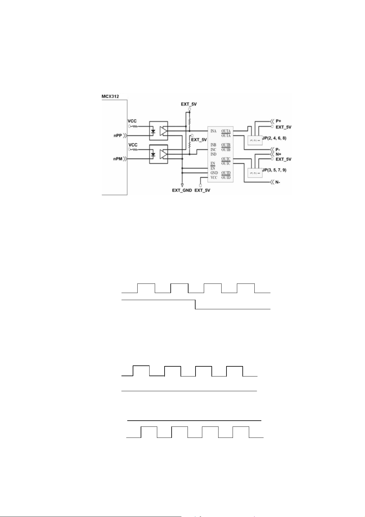
Pulse/Direction Pulse Output Mode:
In Pulse/Direction pulse output mode, the PULSE signal is output only at Pulse
pins (P+, P-). The driving direction is decided from the electric potential of
Direction pins (N+, N-). The following diagram is example signal of
Pulse/Direction pulse output mode.
Negative Command Positive Command
CW/CCW Pulse Output Mode:
In CW/CCW pulse output mode, the PULSE signal is output at both CW pins (P+, P-)
and CCW pins(N+, N-). At the same time, the driving direction is determined
directly. The following diagram is example signal of CW/CCW pulse output mode.
P±
N±
P±
Positive Command
N±
http://www.icpdas.com I8092F Getting Started ManualVer.2.3 20
Negative Command
Page 21
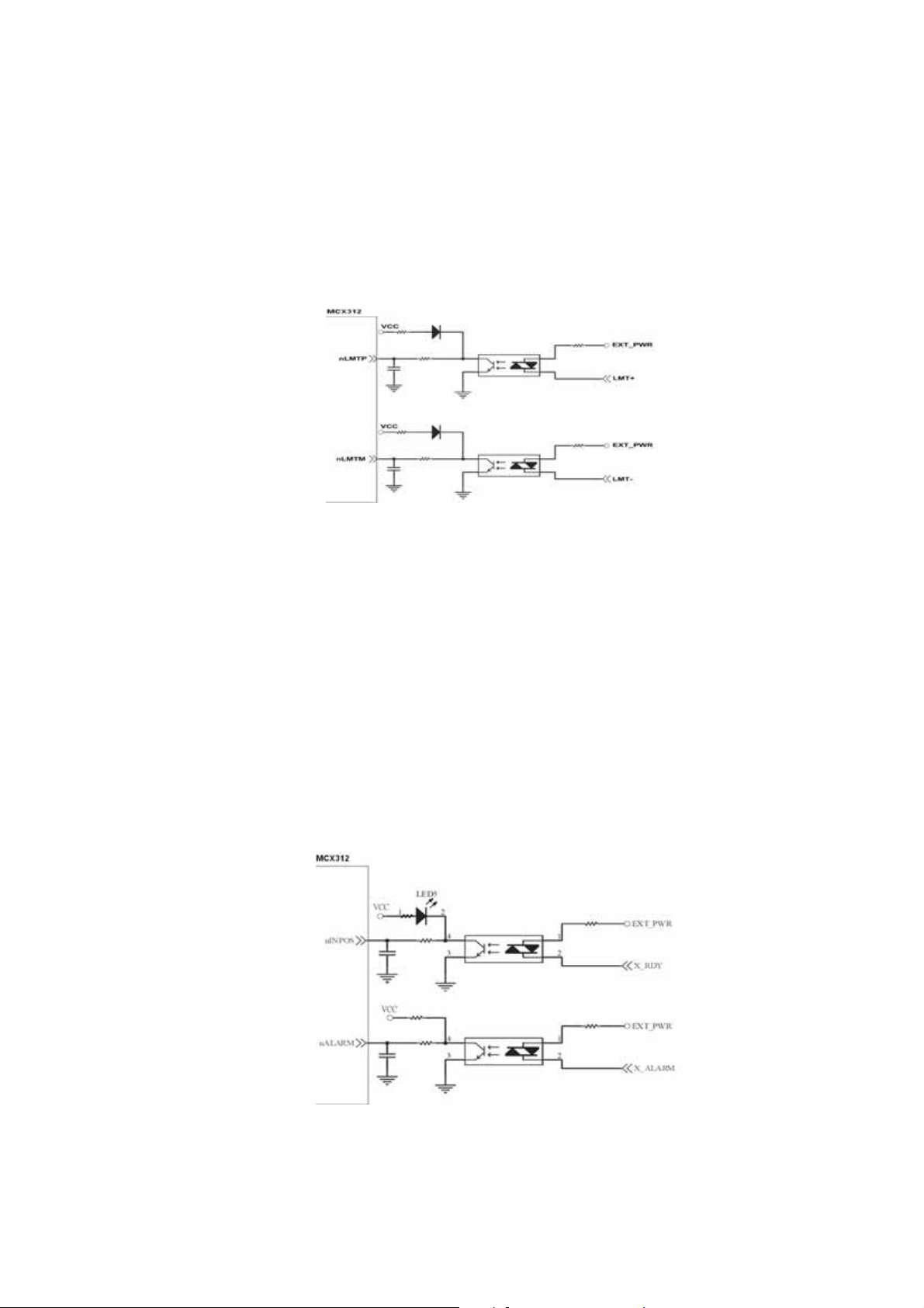
2.3.2 Connection for Limit switch Signal
Limit Switch Signal can prevent the over traveling appearance of the motion
system. User can set the hardware limit switch signal to be normal open or
normal close by the software instruction in I8092F software manual. The
following figure indicates that the photo couplers are used to keep out the sensor
noise of the Limit Switch.
Fig. 2.11 Limit switch signal circuit
2.3.3 General Purpose Input Signals(nINPOS,nALARM)
INPOS is a digital input signal to indicate the In-Position signal of the driver. User
can enable or disable the signal from the software instruction in I8092F software
manual.
ALARM is a digital input signal to indicate the servo alarm signal of the driver.
The output pulse will be stop if I-8092F receives the ALARM signal. User can
enable or disable the signal from the software instruction in I8092F software
manual.
Fig. 2.12 General Digital Input circuit
http://www.icpdas.com I8092F Getting Started ManualVer.2.3 21
Page 22
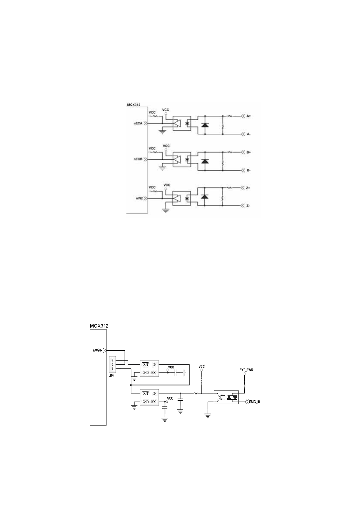
2.3.4 Encoder Signals
The following diagram is for Differential-Type encoder signals. Connect the
Phase A signal to A+ and A- pins and connect Phase B signal to B+ and B- pins.
After the high speed photo coupler isolation, the isolated encoder signals are
connected to motion IC.
Fig. 2.13 Encoder signal connection
2.3.5 Emergency Stop Signal
The following diagram is for Emergency STOP signal. If the emergency signal is
occurred, the output pulse for all axes will be STOP and the error flag will be set as
1. After the photo coupler isolation, the isolated emergency signal is connected
to motion IC.
Fig. 2.14 Emergency Stop Signal connection
http://www.icpdas.com I8092F Getting Started ManualVer.2.3 22
Page 23
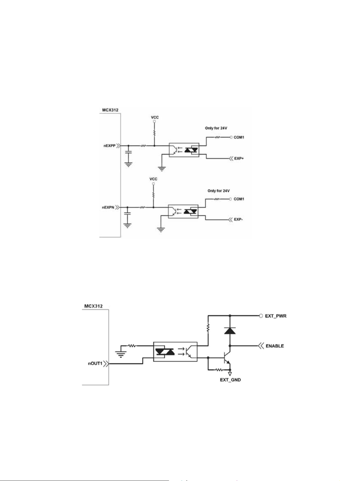
2.3.6 Manual Pulse Generator Input Signal (EXP+,EXP-)
The signals, EXP+ and EXP-, are used for manual pulsar signals. The following
diagram is an example connection for the external inputs. User can set the
signals as fixed pulse CW/CCW mode, continuous pulse CW/CCW mode, or A/B
phase manual pulsar mode by using the setting in section 3.5.
Fig. 2.15 EXP+/- connection diagram
2.3.7 General Purpose Output signals(Servo On/Off)
The following diagram is a digital output signal for driver Servo On/Off signal.
The output signal enable or disable the driver.
Fig. 2.16 Servo On/Off signal connection diagram
http://www.icpdas.com I8092F Getting Started ManualVer.2.3 23
Page 24
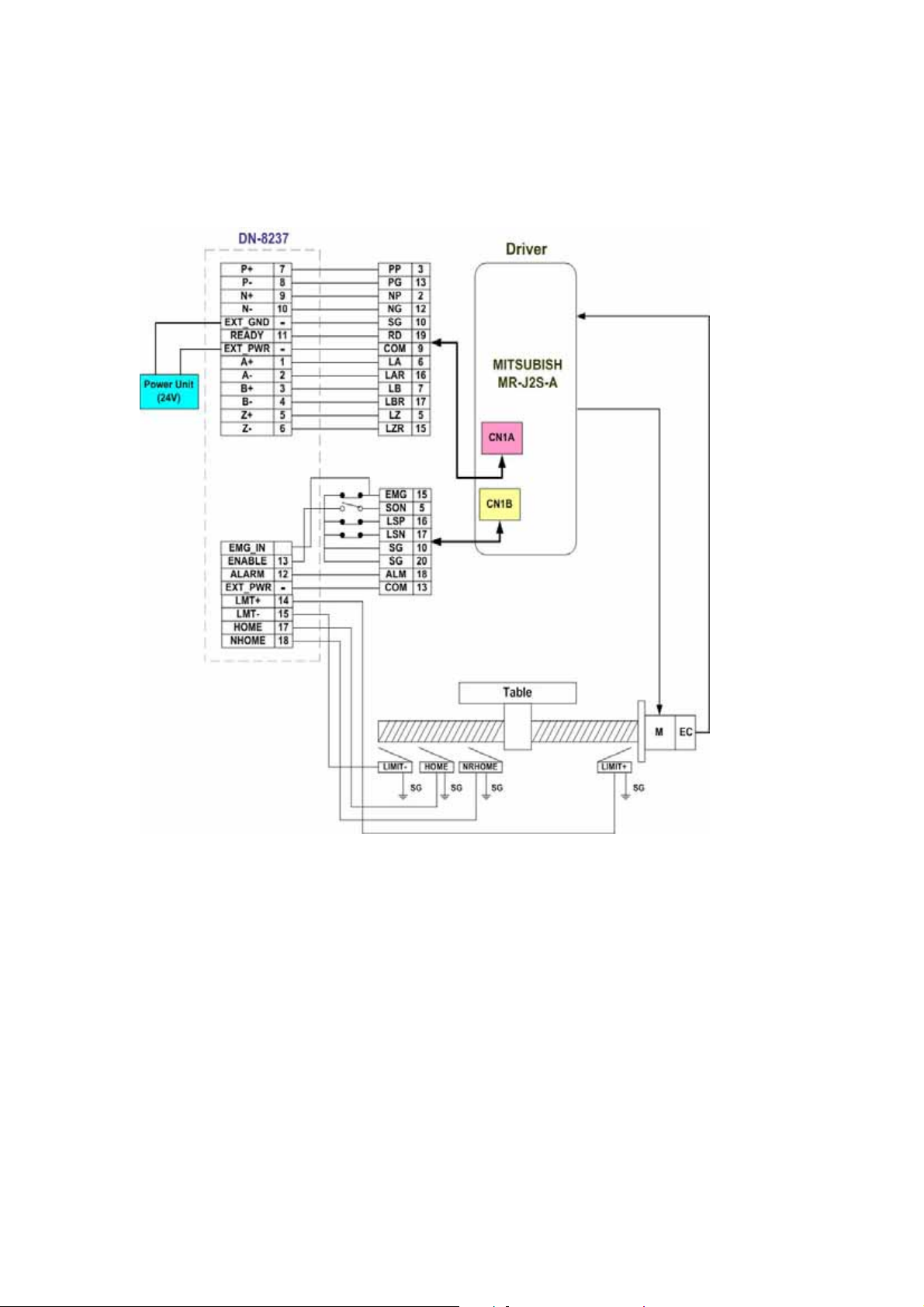
2.4 Connection Example for Motor Driver
The following diagram is the connection example between MITSUBISH MR-J2S AC servo
driver and the extension boardDN-8237.
Fig. 2.17 The connection between MR-J2S AC servo driver and DN-8237 extension board.
http://www.icpdas.com I8092F Getting Started ManualVer.2.3 24
Page 25

3 Software Development Overview
3.1 Software development Overview
The programming following-chart is shown as follows:
The i-8092F software is divided into two parts:
- Driver/Libray/Utilities for WinPAC / XPAC_XPE/XPAC_CE
- Application Programming Interafce (API) for Visual Studio 2005 C++
http://www.icpdas.com I8092F Getting Started ManualVer.2.3 25
Page 26

The C++ API includes the header file (.h) and link file (.lib). These files are installed with
one standard Win32 installation package. Excute the setup.exe, the files will be copied
into the pre-defined directories.
The samples for Visual Studio 2005 C++, wrapper file for Visual Studio 2005 C# and
module for Visual Studio 2005 Basic are provided to demonstrate the related functions.
Please refer to the samples for detail.
http://www.icpdas.com I8092F Getting Started ManualVer.2.3 26
Page 27

3.2 PAC Software Installation
3.2.1 Install i-8092F software in XPAC_CE
The necessary files for XPAC_CE now are packed into one CAB file. In XPAC_CE,
double-click the CAB file will start installation automatically. The files then will be copied
into the specific directories.
When the installation is completed, the driver and library will be copied into the specific
directory defined in XPAC_CE. And the relevant utilities are installed into
\System_Disk\i8092.
The utilities are:
MotionCfg – To configured the i8094/F and i8092F in XPAC_CE. When XPAC_CE
booting up, the OS will refer to those configuration and activate the relative i-8092F
modules.
i8092F EzGo – Provide the similar features of PISO-PS200 EzGo utility. This utility
helps to indicate the status of each axis, configure the polarity of external sensors
and demonstrate the basic/simple motion-controlling models.
i8092F EzFRnet – Demonstrate the FRnet features.
http://www.icpdas.com I8092F Getting Started ManualVer.2.3 27
Page 28

If the software package is installed, one dialog will appear to make sure the ‘re-install’
when CAB updating.
Restart XPAC_CE, the CAB updating will be successful.
http://www.icpdas.com I8092F Getting Started ManualVer.2.3 28
Page 29

3.2.2 Install i-8092F software into WinPAC
The necessary files for WinPAC now are packed into one CAB file. In WinPAC,
double-click the CAB file will start installation automatically. The files then will be copied
into the specific directories.
When the installation is completed, the driver and library will be copied into the specific
directory defined in XPAC_CE. And the relevant utilities are installed into
\System_Disk\i8092.
[Notice]
WinPAC supports addon driver after OS Ver.1.3.0.0. Please check the OS version of target
WinPAC.
The utilities are:
MotionCfg – To configured the i8094/F and i8092F in XPAC_CE. When XPAC_CE
booting up, the OS will refer to those configuration and activate the relative i-8092F
modules.
i8092F EzGo – Provide the similar features of PISO-PS200 EzGo utility. This utility
helps to indicate the status of each axis, configure the polarity of external sensors
and demonstrate the basic/simple motion-controlling models.
i8092F EzFRnet – Demonstrate the FRnet features.
http://www.icpdas.com I8092F Getting Started ManualVer.2.3 29
Page 30

If the software package is installed, one dialog will appear to make sure the ‘re-install’
when CAB updating; and if the driver is used by some activated i-8094/F modules,
WinPAC will show the following message.
Please cancel the CAB installation, remove i-8092F configurations with MotionCfg utility
and excute ‘S
ave and Reboot’ in WinPAC_Utility. Afetr WinPAC re-starting, the CAB
updating will be successful.
http://www.icpdas.com I8092F Getting Started ManualVer.2.3 30
Page 31

3.2.3 Install i-8092F software into XPAC_XPe
The necessary files for XPAC_XPe now are packed into the installation package. In
XPAC_XPe, execute the setup.exe to start installation automatically. These files then will
be copied into the specific directories.
When the installation is completed, the driver and library will be copied into the system
directory defined in Windows XPe. And the relevant utilities are installed into
C:\ICPDAS\I8092F_XPAC_XPe.
[Notice]
The XPAC_XPe protects its hard drive with EWF (Enhanced Write Filter),Before driver installing
or system registry changing, please disable EWF. And enable the EWF after driver installing or
registry changing.
Please refer to chapter 2.4 in xpac_8000_user_manual for detailed EWF settings.
The utilities are:
MotionCfg – To configured the i8094/F and i8092F in XPAC_XPe. When XPAC_XPe
boots up, the OS will refer to those configuration and activate the relative i-8092F
modules.
i8092F EzGo – Provide the similar features of PISO-PS200 EzGo utility. This utility
helps to indicate the status of each axis, configure the polarity of external sensors
and demonstrate the basic/simple motion-controlling models.
i8092F EzFRnet – Demonstrate the FRnet features.
http://www.icpdas.com I8092F Getting Started ManualVer.2.3 31
Page 32

3.3 Motion Configuration Tool
The MotionCfg that is installed with i8092F now supports i-8094/F and i-8092F modules.
The MotionCfg utility helps to Add/Delete the system registries. By these settings,
WinPAC/ XPAC_CE/XPAC_XPe will activate the relative i-8094/F and i-8092F modules
while system booting up.
MotionCfg scans the available i-8094/F and i-8092F modules on backplane, checks the
relevant settings in system registries and the active motion-modules. Then MotionCfg
combines these information and display the status of i-8094/F and i-8092F modules,
including:
Active i-8092F.
None-Configure i-8094/F, indicates the configuration is
needed for the new modules.
Removed i-8094/F, means the configured modules had
been removed.
Failed i-8094/F, indicates some failure occurred while
starting driver.
Unsupported-Module or Empty-Slot.
http:/www.icpdas.com I8094Getting Started Manual for WinPAC Ver.1.1
32
Page 33

[Notice]
In WinPAC, please execute the ‘Save and Reboot’ of WinPAC_Utility to enable the
changes afer re-booting.
In XPAC_XPe, please disable EWF before excuting MotionCfg.exe, and enable EWF after
changing the settings with MotionCfg.exe. Please restart the XPAC_XPe, these setting-changes
will be activated while system booting-up.
http:/www.icpdas.com I8094Getting Started Manual for WinPAC Ver.1.1
33
Page 34

3.4 i8092 EzGo
The initial frame of i8092 EzGo is shown in the following figure. Three categories of test
function are displayed in the initial frame.
Configuration (please refer to section 3.4.1)
Basic Operation (please refer to section 3.4.2)
Interpolation Operation (please refer to section 3.4.3)
http:/www.icpdas.com I8094Getting Started Manual for WinPAC Ver.1.1
34
Page 35

3.4.1 Configuration Dialog
Group Definition & User Guide
1. The tree-structure to show the available axes/cards :
Selects the target Axis of the specific motion module.
2. Encoder Mode :
Configures the encoder input mode as AB phase or CW/CCW (Up/Down count).
Specify the frequency division at AB phase mode. ( 1/1 AB Phase,1/2 AB Phase
and 1/4 AB Phase).
Related Function: i8092_set_enc_cfg().
http:/www.icpdas.com I8094Getting Started Manual for WinPAC Ver.1.1
35
Page 36

3. Output Pulse Mode :
The types of pulse output are classified into 6 modes: 0, 1 is CW/CCW dual
channel mode, 2~5 is PULSE/DIR single channel mode.
Related Function: i8092_set_pls_cfg().
4. Hardware Signals Settings :
The polarities of the hardware signals are set in this sub-item, including
hardware limits(LIMIT+/-), home sensor(HOME), near home sensor(NEAR HOME),
servo motor Z-phase signal(INDEX).
Related Function: i8092_set_limit(), i8092_set_home_cfg().
5. Software Limit Settings :
Reference in section x.2.4
Related Function: i8092_set_softlimit().
6. Servo On/Off Switch :
Related Function: i8092_servo_on().
7. Servo Input Signal :
Configurable feature enable/disable and logical trigger level of the Servo Alarm
signal.
Related Function: i8092_set_alarm(), i8092_set_inp().
8. Input Signals Filter Settings :
Setting the delay time of each input signal filter:
The suitable delay time and the related removable maximum noise width are
listed in the following table:
Code Removable max. noise width Input signal delay time
0 1.75µSEC 2µSEC
1 224µSEC 256µSEC
2 448µSEC 512µSEC
3 896µSEC 1.024 mSEC
4 1.792 mSEC 2.048 mSEC
5 3.584 mSEC 4.096 mSEC
6 7.168 mSEC 8.192 mSEC
7 14.336 mSEC 16.384 mSEC
http:/www.icpdas.com I8094Getting Started Manual for WinPAC Ver.1.1
36
Page 37

Setting the input signals with digital filter:
There are five check box (FE0 ~ FE4) to set the input signals to use digital filter.
FE0 is for Emg. Signal (EMGN), +/- limits (LMT±), Home limit(STOP1), and Near
Home limit(STOP0)
FE1 is for Encoder Z phase signal (STOP2)
FE2 is for Servo In-position signal (INP) and Servo alarm signal (ALM).
FE3 is for +/- external pulse input(EXP+/EXP-).
FE4 is for IN3 signal.
Related Function: i8092_set_filter().
9. INT Factor Settings:
Seven kinds of interrupt event settings are provided in i-8092F motion module
1. Position Counter >= Comp- Counter: Position counter is greater than or equal
to the Negative-comparator.
2. Position Counter < Comp- Counter: Position counter is less than the
Negative-comparator.
3. Position Counter >= Comp+ Counter: Position counter is greater than or equal
to the Positive -comparator.
4. Position Counter < Comp+ Counter: Position counter is less than the Positive
-comparator.
5. End of Constant Speed Drive: The interrupt is triggered when Constant-speed
driving is completed.
6. Start of Constant Speed Drive: The interrupt is triggered when Constant-speed
driving is started.
7. Drive Finished: The interrupt is triggered when the specific axis is stopped.
Related Function: i8092_set_int_factor().
10. Function of Buttons :
To BasicOperation: The shortcut to Basic Operation Dialog.
To Interpolation: The shortcut to Interpolation Dialog.
LoadConfig: Loads the pre-defined configuration.
SaveConfig: Saves the configuration of all available i8094/F modules.
Return:Returns to initial frame.
11. Status Bar :
Displays the Error Status
http:/www.icpdas.com I8094Getting Started Manual for WinPAC Ver.1.1
37
Page 38

3.4.2 Basic Operation Dialog
Group Definition & User Guide
1. The tree-structure to show the available axes/cards :
Selects the target Axis of the specific motion module.
2. Parameter Setting :
The involved parameters are:
Start Velocity(SV), Driver Velocity(V), Acceleration(A), Deceleration(D), Jerk(K),
Deceleration Rate(L), Output Pulse(P) and Offset Pulse(AO).
3. Driving Mode :
Point-to-point driving modes.
Continuous output driving modes.
http:/www.icpdas.com I8094Getting Started Manual for WinPAC Ver.1.1
38
Page 39

MPG driving modes.
4. Speed Profile :
Const Velocity mode.
T-Profile mode.
S-Curve mode.
5. Acc/Dec Symmetry Setting :
Symmetry Mode.
Asymmetry Mode.
6.
Manual Pulse Generator Setting :
The maximum frequency of MPG and output-pulse ratio are required.
7. Servo On/Off Status :
Indicates the current Servo status (On or Off).
8. Axis Status :
Displays the motion information for each axis, including the logic position
counter, encoder position counter, current speed and acceleration.
Related Function: i8092_get_cmdcounter(), i8092_get_enccounter(),
i8092_get_speed() and i8092_get_acc().
9. Limit Switch and Homing Signals :
Indicates the status of limit switches and home-related sensors.
Related Function: i8092_get_mdi_status().
10. Servo Input Signal :
Displays servo Input signal status.
11. Function of Buttons :
To Config : The shortcut to Configuration Dialog.
Reset : Resets the target card to the initial state.
Reverse : Starts motion in the reverse direction.
Stop : Stops Motion.
Forward : Starts motion in the forward direction.
Return : Returns to initial frame.
http:/www.icpdas.com I8094Getting Started Manual for WinPAC Ver.1.1
39
Page 40

3.4.3 Interpolation Dialog
Group Definition & User Guide
1. The tree-structure to show the available axes/cards :
Selects the target motion module.
2. Interpolation Mode Setting :
Linear 2D and Circular interpolation.
Related Function : i8092_t_line2_move(), i8092_s_line2_move() and
i8092_t_arc2_move().
3. Acc Mode Setting :
Three acceleration modes are supported for interpolation:
http:/www.icpdas.com I8094Getting Started Manual for WinPAC Ver.1.1
40
Page 41

Constant-Speed, T-Profile and S-Curve acceleration modes.
4. Axis Disposition Setting :
Configures the axes that are related to interpolation operation.
5. Parameter Setting :
The involved parameters are :
Start Velocity(SV), Driver Velocity(V), Acceleration(A), Deceleration(D), Jerk(K)、
Deceleration Rate(L), Output Pulse(P) and Offset Pulse(AO).
6. Arc Mode Setting :
Indicates the direction of Circular Interpolation. Clockwise or Counter Clockwise
in circular motion.
7. Acc/Dec Symmetry Setting :
Symmetry Mode.
Asymmetry Mode.
8. Servo On/Off Status :
Indicates the current Servo status (On or Off).
9. Finish Points /Center Points Setting : Configures the each Finish-point of the
interpolation-related axes; and the Center-Points for circular
interpolation.
10. Position Status :
Displays the motion information for each axis, including the logic position
counter, encoder position counter and current speed.
Related Function : i8092_get_cmdcounter(), i8092_get_enccounter(),
i8092_get_speed().
11. Function of Buttons :
To Config : The shortcut to Configuration Dialog.
Reset : Resets the target card to the initial state.
Interpolation Move : Starts Interpolation motion.
Stop : Stops Motion.
Return : Returns to initial frame.
http:/www.icpdas.com I8094Getting Started Manual for WinPAC Ver.1.1
41
Page 42

3.5 EzFRnet
Group Definition & User Guide
1. The tree-structure to show the available FRnet DI modules :
Selects the target motion module.
2. SAn (Digital Input) Status :
Select the Group Address for specific FRnet DI module.
Displays the DI status of target FRnet module.
Related Function:i8092_get_FRnet_DI()。
3. RAn (Digital Output) Set :
Select the Group Address for specific FRnet DO module.
Sets the Digital Output to the DO module.
Related Function:i8092_set_FRnet_DO()
http:/www.icpdas.com I8094Getting Started Manual for WinPAC Ver.1.1
42
Page 43

3.6 Install Software Development Package
3.6.1 Installs SDK on WinPAC/XPAC_CE
i-8092F provides the API that helps programmer to develop their programs in Microsoft®
eMbedded Visual C++ and Visual Studio 2005 C++. Please excute setup.exe in the
WindowsNT/Wndows200/WindowsXP that the WinPAC /XPAC_CE SDK had been
installed, the necessary header file (.h) and link file (.lib) will be copied into pre-defined
directories.
$Installed_Directory
Manuals\ The related documentation.
eVC\
VS2005\
Lib\ The Link file(.lib) for eVC programming.
Include\ The header file(.h) for eVC programming.
Samples\ eVC samples
Lib\ The Link file(.lib) for VS2005 programming.
Include\
Cpp\ VS2005 C++ Samples
CSharp\ VS2005 C# Samples.
VB\
The header file(.h), wrapper file(.vc) and
modules(.vb) for VS2005 programming.
VS2005 VB Samples.
(For instance, the installed directory of WinPAC package is ‘C:\ICPDAS\i8092_WinPAC’ typically)
Open that sample Project/Workspace, all settings of reference-platform, compiler and
linker had been pre-configured. If the Platform SDK, PAC270 / XPacSDK_CE, does not
appear in relative combo-box, please refer to the WinPAC /XPAC_CE documentation to
install the relative SDK.
Open the Project / WorkSpace will bring out all of the settings,Including the
definition files needed by the reference directory, the required link to file name and
reference directory.
http:/www.icpdas.com I8094Getting Started Manual for WinPAC Ver.1.1
43
Page 44

http:/www.icpdas.com I8094Getting Started Manual for WinPAC Ver.1.1
44
Page 45

3.6.2 Installs SDK on XPAC_XPe
i-8092F provides API that helps programmers to develop their programs in
Microsoft® Visual Studio C++ / C# / VB.net.
Please excute setup.exe in the
WindowsNT/Wndows200/WindowsXP, the necessary header file (.h) and link file (.lib) will
be copied into pre-defined directories.
$Installed_Directory
(For instance, the installed directory of XPAC_XPe package is ‘C:\ICPDAS\i8092_XPAC_XPe’ typically)
Manuals\ The related documentation.
VC6\
VS2005\
Lib\ The Link file(.lib) for eVC programming.
Include\ The header file(.h) for eVC programming.
Samples\
Lib\ The Link file(.lib) for VS2005 programming.
Include\
CSharp\ VS2005 C# Samples.
VB\
VC6 samples
The header file(.h), wrapper file(.vc) and
modules(.vb) for VS2005 programming.
VS2005 VB Samples.
http:/www.icpdas.com I8094Getting Started Manual for WinPAC Ver.1.1
45
Page 46

APPENDIX A Other Terminal Boards
A.1 DN-8237-DB Daughter Board
The DN-8237DB is the daughter board for Delta ASDA-A Series Ampilifier. It has 2-axis
I/O signals.
A.1.1 Board Layout for DN-8237-DB
107mm
JP2
110mm
EMG
SW
CN2
TB2
JP5
CN-Y
CON1
RJ1
CN-X
Y X
37 PIN CONNECTOR
DN-8237-DB
TB1
Fig. B1-1 Board layout for the DN-8237-DB
JP1
CN1
http:/www.icpdas.com I8094Getting Started Manual for WinPAC Ver.1.1
46
Page 47

A.1.2 Signal Connections for DN-8237-DB
Maintaining signal connections is one of the most important factors in ensuring that your
application system is sending and receiving data correctly.
Pin Assignment for CON1
The I/O connector on the DN-8237-DB is a 37-pin connector that enables you to connect to
the PISO-PS200 or I-8092F motion card. Fig. B1-2 shows the pin assignment for the 37-pin
I/O connector on the DN-8237-DB (or on the motion card), and refer to Table B1-2 for
description of each motion I/O signal.
Fig. B1-2 I/O connector pin assignment for the CON1
http:/www.icpdas.com I8094Getting Started Manual for WinPAC Ver.1.1
47
Page 48

Table B1-2 DN-8237-DB CON1 I/O connector signal description
Pin name Pin number Description
FR_A 19 FRnet A-phase signal
FR_B 37 FRnet B-phase signal
X_ECA 18 Encoder A-phase signal for the X axis
Y_ECA 36 Encoder A-phase signal for the Y axis
X_ECB 17 Encoder B-Phase signal for the X axis
Y_ECB 35 Encoder B-Phase signal for the Y axis
X_STOP2 16 Stop 2 signal for the X axis
Y_STOP2 34 Stop 2 signal for the Y axis
X_INPOS 15 In-position signal for the X axis
Y_INPOS 33 In-position signal for the Y axis
X_ALARM 14 Alarm signal for the X axis
Y_ALARM 32 Alarm signal for the Y axis
X_LMTP 13 Limit switch input signal (+) for the X axis
Y_LMTP 31 Limit switch input signal (+) for the Y axis
X_LMTM 12 Limit switch input signal (-) for the X axis
Y_LMTM 30 Limit switch input signal (-) for the Y axis
X_STOP0 11 Stop 0 signal for the X axis
Y_STOP0 29 Stop 0 signal for the Y axis
X_STOP1 10 Stop 1 signal for the X axis
Y_STOP1 28 Stop 1 signal for the Y axis
X_IN3 9 Input 3 signal for the X axis
Y_IN3 27 Input 3 signal for the Y axis
X_EXPP 8
Y_EXPP 26
X_EXPM 7
Y_EXPM 25
X_OUT0 6
Y_OUT0 24
X_OUT1 5
Y_OUT1 23
XPP 4
YPP 22
XPM 3
YPM 21
EXT pulsar input signal (+) for the X axis
EXT pulsar input signal (+) for the Y axis
EXT pulsar input signal (-) for the X axis
EXT pulsar input signal (-) for the Y axis
Output 0 signal for the X axis
Output 0 signal for the Y axis
Output 1 signal for the X axis
Output 1 signal for the Y axis
Driving pulsar signal (+) for the X axis
Driving pulsar signal (+) for the Y axis
Driving pulsar signal (+) for the X axis
Driving pulsar signal (+) for the Y axis
EMGN 2 Emergency stop input signal
VCC 20 Module power (+5V)
GND 1 Ground
http:/www.icpdas.com I8094Getting Started Manual for WinPAC Ver.1.1
48
Page 49

TB1
The connector TB1 is 7-pin connector that enables you to connect to the signals of your
motor drivers. Fig.B1-3 shows the pin assignment for the 7-pin connector on the
DN-8237-DB, and the Table B1-3 shows its I/O connector signal description.
TB2
The connector TB2 is 5-pin connector that enables you to connect to the signals of your
motor drivers. Fig.B1-4 shows the pin assignment for the 5-pin connector on the
DN-8237-DB, and the Table B1-4 shows its I/O connector signal description.
http:/www.icpdas.com I8094Getting Started Manual for WinPAC Ver.1.1
49
Page 50

CN-X & CN-Y (CN1 connector for each AXIS in Driver)
The connectors CN-X and CN-Y are 50-pin connectors that enable you to connect to the
CN1 connector of Delta ASDA-A series motor drivers. Fig.B1-5 shows the pin
assignment for the 50-pin connector on the DN-8468-DB, and the Table B1-5 shows its I/O
connector signal description.
http:/www.icpdas.com I8094Getting Started Manual for WinPAC Ver.1.1
50
Page 51

CN1 & CN2 (The I/O signals of the X and Y AXIS )
The connectors CN1 and CN2 are 11-pin connectors that enable you to connect to the
signals of your motor drivers. Fig.B1-6 shows the pin assignment for the 20-pin connector
on the DN-8237-DB, and the Table B1-6 shows its I/O connector signal description.
RJ1 (The I/O signals of the FRnet)
The connectors RJ1 is an 8-pin RJ45 connector that enable you to connect to the signals
of FRnet. Fig.B1-7 shows the pin assignment for the 8-pin connector on the DN-8237-DB,
and the Table B1-7 shows its I/O connector signal description.
http:/www.icpdas.com I8094Getting Started Manual for WinPAC Ver.1.1
51
Page 52

A.1.3 Jumper and Switch Settings
JP5
Jumper 5 controls the EMG-A signal of the TB1 connector. The following diagram is
shown the selection condition of the jumper 5.
Fig. B1-8 Jumper 5 setting
http:/www.icpdas.com I8094Getting Started Manual for WinPAC Ver.1.1
52
Page 53

SW 1
The emergency stop signal for each servo ampilfier can be selected from SW1. The
number 1 and 2 on SW1 are denoted as axis X and Y, respectively. The number 3 and 4
on SW1 are reserved for future work. Fig. B1-9 is the default setting to connect the EMG
singals to GND. The EMG signals from CN1 and CN2 will not take effect. If the switch is
disconnected as shown in Fig. B1-10, the emergency stop signals can be controlled from
EMG signals in CN1 and CN2.
Fig. B1-9 SW1 setting for normally GND (Default setting)
Fig. B1-10 SW1 setting for user controlled signals.
http:/www.icpdas.com I8094Getting Started Manual for WinPAC Ver.1.1
53
Page 54

JP1 ~ JP2
Jumper 1 ~ Jumper 2 can select the reset function in CN1 and CN2 for each axis. The
following diagram is shown the selection condition of the JP1.
Fig. B1-15 JP 1 and 2 setting
http:/www.icpdas.com I8094Getting Started Manual for WinPAC Ver.1.1
54
Page 55

A.2 DN-8237-MB Daughter Board
The DN-8237MB is the daughter board for Mitsubishi J2 Series Ampilifier. It has 2-axis
I/O signals.
A.2.1 Board Layout for DN-8237-MB
107mm
110mm
CN-YA
CN2
DN-8237-MB
TB2
SW
EMG
CN-YB
Y X
CON1
37 PIN CONNECTOR
RJ1
JP5
CN-XB
TB1
Fig. B2-1 Board layout for the DN-8237-MB
CN-XA
CN1
http:/www.icpdas.com I8094Getting Started Manual for WinPAC Ver.1.1
55
Page 56

A.2.2 Signal Connections for DN-8237-MB
Maintaining signal connections is one of the most important factors in ensuring that your
application system is sending and receiving data correctly.
Pin Assignment for CON1
The I/O connector on the DN-8237-MB is a 37-pin connector that enables you to connect to
the PISO-PS200 or I-8092F motion card. Fig. B2-2 shows the pin assignment for the 37-pin
I/O connector on the DN-8237-MB (or on the motion card), and refer to Table B2-2 for
description of each motion I/O signal.
Fig. B2-2 I/O connector pin assignment for the CON1
http:/www.icpdas.com I8094Getting Started Manual for WinPAC Ver.1.1
56
Page 57

Table B2-2 DN-8237-MB CON1 I/O connector signal description
Pin name Pin number Description
FR_A 19 FRnet A-phase signal
FR_B 37 FRnet B-phase signal
X_ECA 18 Encoder A-phase signal for the X axis
Y_ECA 36 Encoder A-phase signal for the Y axis
X_ECB 17 Encoder B-Phase signal for the X axis
Y_ECB 35 Encoder B-Phase signal for the Y axis
X_STOP2 16 Stop 2 signal for the X axis
Y_STOP2 34 Stop 2 signal for the Y axis
X_INPOS 15 In-position signal for the X axis
Y_INPOS 33 In-position signal for the Y axis
X_ALARM 14 Alarm signal for the X axis
Y_ALARM 32 Alarm signal for the Y axis
X_LMTP 13 Limit switch input signal (+) for the X axis
Y_LMTP 31 Limit switch input signal (+) for the Y axis
X_LMTM 12 Limit switch input signal (-) for the X axis
Y_LMTM 30 Limit switch input signal (-) for the Y axis
X_STOP0 11 Stop 0 signal for the X axis
Y_STOP0 29 Stop 0 signal for the Y axis
X_STOP1 10 Stop 1 signal for the X axis
Y_STOP1 28 Stop 1 signal for the Y axis
X_IN3 9 Input 3 signal for the X axis
Y_IN3 27 Input 3 signal for the Y axis
X_EXPP 8
Y_EXPP 26
X_EXPM 7
Y_EXPM 25
X_OUT0 6
Y_OUT0 24
X_OUT1 5
Y_OUT1 23
XPP 4
YPP 22
XPM 3
YPM 21
EXT pulsar input signal (+) for the X axis
EXT pulsar input signal (+) for the Y axis
EXT pulsar input signal (-) for the X axis
EXT pulsar input signal (-) for the Y axis
Output 0 signal for the X axis
Output 0 signal for the Y axis
Output 1 signal for the X axis
Output 1 signal for the Y axis
Driving pulsar signal (+) for the X axis
Driving pulsar signal (+) for the Y axis
Driving pulsar signal (+) for the X axis
Driving pulsar signal (+) for the Y axis
EMGN 2 Emergency stop input signal
VCC 20 Module power (+5V)
GND 1 Ground
http:/www.icpdas.com I8094Getting Started Manual for WinPAC Ver.1.1
57
Page 58

TB2
The connector TB2 is 7-pin connector that enables you to connect to the signals of your
motor drivers. Fig.B2-3 shows the pin assignment for the 7-pin connector on the
DN-8237-MB, and the Table B2-3 shows its I/O connector signal description.
Table B2-3 TB2 Signal Connection
Name Number Description
FR-A 7 FRnet port A
FR-B 6 FRnet port B
XOUT0 5 General output 0 for X
axis
YOUT0 4 General output 0 for X
axis
NC 3 No connection
EMG-A 2 EMG input signal for all
axis
EXT_GND 1 EXT POWER Ground
Fig B2-3 Pin definition for TB2
http:/www.icpdas.com I8094Getting Started Manual for WinPAC Ver.1.1
58
Page 59

TB1
The connector TB1 is 5-pin connector that enables you to connect to the signals of your
motor drivers. Fig.B2-4 shows the pin assignment for the 5-pin connector on the
DN-8237-MB, and the Table B2-4 shows its I/O connector signal description.
Table B2-4 TB1 Signal Connection
Fig B2-4 Pin definition for TB1
Name Number Description
EXT_PWR 1 EXT POWER 24V
EXT_PWR 2 EXT POWER 24V
EXT_GND 3 EXT POWER Ground
EXT_GND 4 EXT POWER Ground
FGND 5 Frame Ground
http:/www.icpdas.com I8094Getting Started Manual for WinPAC Ver.1.1
59
Page 60

CN-XA & CN-YA (Fig B2-5 connector for each AXIS )
The connectors CN-XA and CN-YA are 20-pin connectors that enable you to connect to the
CNA connector of Mitsubishi motor drivers. Fig.B2-5 shows the pin assignment for the
20-pin connector on the DN-8237-MB, and the Table B2-5 shows its I/O connector signal
description.
Table B2-5 CN-X A,CN-YA
Name Number Description
EXT_GND 1 EXT POWER Ground
N+ 2 Negative Direction
Pulse(+)
P+ 3 Positive Direction
Pulse(+)
NC 4 No connection
Z+ 5 Encoder Z-phase(+)
A+ 6 Encoder A-phase(+)
B+ 7 Encoder B-phase(+)
ERC 8 Error Count Clear
EXT_PWR 9 EXT POWER 24V
EXT_GND 10 EXT POWER Ground
NC 11 No connection
N- 12 Negative Direction
Pulse(-)
P- 13 Positive Direction Pulse
(-)
NC 14 No connection
Z- 15 Encoder Z-phase(-)
A- 16 Encoder A-phase (-)
B- 17 Encoder B-phase (-)
Fig B2-5 Pin definition for CN-XA,
CN-YA
INPOS 18 Servo In Position
RDY 19 Servo Ready
EXT_GND 20 EXT POWER Ground
http:/www.icpdas.com I8094Getting Started Manual for WinPAC Ver.1.1
60
Page 61

CN-XB & CN-YB (Fig B2-6 connector for each AXIS )
The connectors CN-XB and CN-YB are 20-pin connectors that enable you to connect to
the CNB connector of your motor drivers. Fig.B2-6 shows the pin assignment for the
20-pin connector on the DN-8237-MB, and the Table B2-6 shows its I/O connector signal
description.
Table B2-6 CN-XB ,CN-YB
Name Number Description
EXT_GND 1 EXT POWER Ground
NC 2 No connection
NC 3 No connection
NC 4 No connection
SVON 5 Servo On
NC 6 No connection
NC 7 No connection
NC 8 No connection
NC 9 No connection
EXT_GND 10 EXT POWER Ground
NC 11 No connection
NC 12 No connection
EXT_PWR 13 EXT POWER 24V
Fig B2-6 Pin definition for CN-XB,
CN-YB
http:/www.icpdas.com I8094Getting Started Manual for WinPAC Ver.1.1
RESET 14 Servo Reset
EMG 15 Emergent Stop
EXT_GND 16 EXT POWER Ground
EXT_GND 17 EXT POWER Ground
ALARM 18 Servo Alarm
NC 19 No connection
EXT_GND 20 EXT POWER Ground
61
Page 62

CN1 & CN2 (The I/O signals of the X and Y AXIS )
The connectors CN1 and CN2 are 11-pin connectors that enable you to connect to the
signals of your motor drivers. Fig.B2-7 shows the pin assignment for the 20-pin connector
on the DN-8237-MB, and the Table B2-7 shows its I/O connector signal description.
Table B2-7 CN1~CN2
Name Number Description
ERC 12 Error Count Clear
EXT_PWR 11 EXT POWER 24V
EMG 10 Emergent Stop
LMT+ 9 Limit switch Input
Signal(+)
LMT- 8 Limit switch Input
Signal(-)
INPUT3 7 Input Signal (IN3)
NRHOME 6 Near HOME Sensor Input
Signal
HOME 5 HOME Sensor Input
Signal
RESET 4 RESET Input Signal
EXP+ 3 EXT Positive Direction
Pulse(+)
EXP- 2 EXT Positive Direction
Fig B2-7 Pin definition for CN1~ CN2
EXT_GND 1 EXT POWER Ground
http:/www.icpdas.com I8094Getting Started Manual for WinPAC Ver.1.1
62
Pulse(-)
Page 63

RJ1 (The I/O signals of the FRnet)
The connectors RJ1 is an 8-pin RJ45 connector that enable you to connect to the signals
of FRnet. Fig.B2-8 shows the pin assignment for the 8-pin connector on the DN-8237-MB,
and the Table B2-8 shows its I/O connector signal description.
A2.3 Jumper and Switch Settings
JP5
Jumper 5 controls the EMG-A signal of the TB1 connector. The following diagram is
shown the selection condition of the jumper 5.
Fig. B2-9 Jumper 5 setting
http:/www.icpdas.com I8094Getting Started Manual for WinPAC Ver.1.1
63
Page 64

SW 1
The emergency stop signal for each servo ampilfier can be selected from SW1. The
number 1 and 2 on SW1 are denoted as axis X and Y, respectively. The number 3 and 4
on SW1 are reserved for future work. Fig. B2-10 is the default setting to connect the EMG
singals to GND. The EMG signals from CN1 and CN2 will not take effect. If the switch is
disconnected as shown in Fig. B2-11, the emergency stop signals can be controlled from
EMG signals in CN1 and CN2.
Fig. B2-10 SW1 setting for normally GND (Default setting)
Fig. B2-11 SW1 setting for user controlled signals.
http:/www.icpdas.com I8094Getting Started Manual for WinPAC Ver.1.1
64
Page 65

A.3 DN-8237-PB Daughter Board
The DN-8237PB is the daughter board for Panasonic A4 Series Ampilifier. It has 2-axis
I/O signals.
A.3.1 Board Layout for DN-8237-PB
107mm
110mm
EMG
SW
CN2
TB2
JP5
CN-Y
CON1
RJ1
CN-X
Y X
37 PIN CONNECTOR
DN-8237-PB
TB1
Fig. B3-1 Board layout for the DN-8237-PB
CN1
http:/www.icpdas.com I8094Getting Started Manual for WinPAC Ver.1.1
65
Page 66

A.3.2 Signal Connections for DN-8237-PB
Maintaining signal connections is one of the most important factors in ensuring that your
application system is sending and receiving data correctly.
Pin Assignment for CON1
The I/O connector on the DN-8237-PB is a 37-pin connector that enables you to connect to
the PISO-PS200(or I-8092F) motion card. Fig. B3-2 shows the pin assignment for the
37-pin I/O connector on the DN-8237-PB (or on the motion card), and refer to Table B3-2
for description of each motion I/O signal.
Fig. B3-2 I/O connector pin assignment for the CON1
http:/www.icpdas.com I8094Getting Started Manual for WinPAC Ver.1.1
66
Page 67

Table B3-2 DN-8237-PB CON1 I/O connector signal description
Pin name Pin number Description
FR_A 19 FRnet A-phase signal
FR_B 37 FRnet B-phase signal
X_ECA 18 Encoder A-phase signal for the X axis
Y_ECA 36 Encoder A-phase signal for the Y axis
X_ECB 17 Encoder B-Phase signal for the X axis
Y_ECB 35 Encoder B-Phase signal for the Y axis
X_STOP2 16 Stop 2 signal for the X axis
Y_STOP2 34 Stop 2 signal for the Y axis
X_INPOS 15 In-position signal for the X axis
Y_INPOS 33 In-position signal for the Y axis
X_ALARM 14 Alarm signal for the X axis
Y_ALARM 32 Alarm signal for the Y axis
X_LMTP 13 Limit switch input signal (+) for the X axis
Y_LMTP 31 Limit switch input signal (+) for the Y axis
X_LMTM 12 Limit switch input signal (-) for the X axis
Y_LMTM 30 Limit switch input signal (-) for the Y axis
X_STOP0 11 Stop 0 signal for the X axis
Y_STOP0 29 Stop 0 signal for the Y axis
X_STOP1 10 Stop 1 signal for the X axis
Y_STOP1 28 Stop 1 signal for the Y axis
X_IN3 9 Input 3 signal for the X axis
Y_IN3 27 Input 3 signal for the Y axis
X_EXPP 8
Y_EXPP 26
X_EXPM 7
Y_EXPM 25
X_OUT0 6
Y_OUT0 24
X_OUT1 5
Y_OUT1 23
XPP 4
YPP 22
XPM 3
YPM 21
EXT pulsar input signal (+) for the X axis
EXT pulsar input signal (+) for the Y axis
EXT pulsar input signal (-) for the X axis
EXT pulsar input signal (-) for the Y axis
Output 0 signal for the X axis
Output 0 signal for the Y axis
Output 1 signal for the X axis
Output 1 signal for the Y axis
Driving pulsar signal (+) for the X axis
Driving pulsar signal (+) for the Y axis
Driving pulsar signal (+) for the X axis
Driving pulsar signal (+) for the Y axis
EMGN 2 Emergency stop input signal
VCC 20 Module power (+5V)
GND 1 Ground
http:/www.icpdas.com I8094Getting Started Manual for WinPAC Ver.1.1
67
Page 68

TB1
The connector TB1 is 7-pin connector that enables you to connect to the signals of your
motor drivers. Fig.B3-3 shows the pin assignment for the 7-pin connector on the
DN-8237-PB, and the Table B3-3 shows its I/O connector signal description.
TB2
The connector TB2 is 5-pin connector that enables you to connect to the signals of your
motor drivers. Fig.B3-4 shows the pin assignment for the 5-pin connector on the
DN-8237-PB, and the Table B3-4 shows its I/O connector signal description.
http:/www.icpdas.com I8094Getting Started Manual for WinPAC Ver.1.1
68
Page 69

CN-X &CN-Y(CN X5 connector for each Axis in Driver)
The connectors CN-X and CN-Y are 50-pin connectors that enable you to connect to the
CN X5 connector of Panasonic motor drivers. Fig.B3-5 shows the pin assignment for the
50-pin connector on the DN-8468-PB, and the Table B3-5 shows its I/O connector signal
description.
http:/www.icpdas.com I8094Getting Started Manual for WinPAC Ver.1.1
69
Page 70

CN1& CN2 (The I/O signals of the X and Y axis)
The connectors CN1 and CN2 are 11-pin connectors that enable you to connect to the
signals of your motor drivers. Fig.B3-6 shows the pin assignment for the 20-pin connector
on the DN-8237-PB, and the Table B3-6 shows its I/O connector signal description.
RJ1 (The I/O signals of the FRnet)
The connectors RJ1 is an 8-pin RJ45 connector that enable you to connect to the signals
of FRnet. Fig.B3-7 shows the pin assignment for the 8-pin connector on the DN-8237-PB,
and the Table B3-7 shows its I/O connector signal description.
http:/www.icpdas.com I8094Getting Started Manual for WinPAC Ver.1.1
70
Page 71

A.3.3 Jumper and Switch Settings
JP5
Jumper 5 controls the EMG-A signal of the TB1 connector. The following diagram is
shown the selection condition of the jumper 5.
Fig. B3-8 Jumper 5 setting
http:/www.icpdas.com I8094Getting Started Manual for WinPAC Ver.1.1
71
Page 72

SW 1
The emergency stop signal for each servo ampilfier can be selected from SW1. The
number 1 and 2 on SW1 are denoted as axis X and Y, respectively. The number 3 and 4
on SW1 are reserved for future work. Fig. B3-9 is the default setting to connect the EMG
singals to GND. The EMG signals from CN1 and CN2 will not take effect. If the switch is
disconnected as shown in Fig. B3-10, the emergency stop signals can be controlled from
EMG signals in CN1 and CN2.
Fig. B3-9 SW1 setting for normally GND (Default setting)
Fig. B3-10 SW1 setting for user
http:/www.icpdas.com I8094Getting Started Manual for WinPAC Ver.1.1
72
Page 73

A.4 DN-8237-YB Daughter Board
The DN-8237YB is the daughter board for Yaskawa Series Ampilifier. It has 2-axis I/O
signals.
A.4.1 Board Layout for DN-8237-YB
107mm
110mm
EMG
SW
CN2
TB2
JP5
CN-Y
CON1
RJ1
CN-X
Y X
37 PIN CONNECTOR
DN-8237-YB
TB1
Fig. B4-1 Board layout for the DN-8237-YB
CN1
http:/www.icpdas.com I8094Getting Started Manual for WinPAC Ver.1.1
73
Page 74

A.4.2 Signal Connections for DN-8237-YB
Maintaining signal connections is one of the most important factors in ensuring that your
application system is sending and receiving data correctly.
Pin Assignment for CON1
The I/O connector on the DN-8237-YB is a 37-pin connector that enables you to connect to
the PISO-PS200 or I-8092F motion card. Fig. B4-2 shows the pin assignment for the 37-pin
I/O connector on the DN-8237-YB (or on the motion card), and refer to Table B4-2 for
description of each motion I/O signal.
Fig. B4-2 I/O connector pin assignment for the CON1
http:/www.icpdas.com I8094Getting Started Manual for WinPAC Ver.1.1
74
Page 75

Table B4-2 DN-8237-YB CON1 I/O connector signal description
Pin name Pin number Description
FR_A 19 FRnet A-phase signal
FR_B 37 FRnet B-phase signal
X_ECA 18 Encoder A-phase signal for the X axis
Y_ECA 36 Encoder A-phase signal for the Y axis
X_ECB 17 Encoder B-Phase signal for the X axis
Y_ECB 35 Encoder B-Phase signal for the Y axis
X_STOP2 16 Stop 2 signal for the X axis
Y_STOP2 34 Stop 2 signal for the Y axis
X_INPOS 15 In-position signal for the X axis
Y_INPOS 33 In-position signal for the Y axis
X_ALARM 14 Alarm signal for the X axis
Y_ALARM 32 Alarm signal for the Y axis
X_LMTP 13 Limit switch input signal (+) for the X axis
Y_LMTP 31 Limit switch input signal (+) for the Y axis
X_LMTM 12 Limit switch input signal (-) for the X axis
Y_LMTM 30 Limit switch input signal (-) for the Y axis
X_STOP0 11 Stop 0 signal for the X axis
Y_STOP0 29 Stop 0 signal for the Y axis
X_STOP1 10 Stop 1 signal for the X axis
Y_STOP1 28 Stop 1 signal for the Y axis
X_IN3 9 Input 3 signal for the X axis
Y_IN3 27 Input 3 signal for the Y axis
X_EXPP 8
Y_EXPP 26
X_EXPM 7
Y_EXPM 25
X_OUT0 6
Y_OUT0 24
X_OUT1 5
Y_OUT1 23
XPP 4
YPP 22
XPM 3
YPM 21
EXT pulsar input signal (+) for the X axis
EXT pulsar input signal (+) for the Y axis
EXT pulsar input signal (-) for the X axis
EXT pulsar input signal (-) for the Y axis
Output 0 signal for the X axis
Output 0 signal for the Y axis
Output 1 signal for the X axis
Output 1 signal for the Y axis
Driving pulsar signal (+) for the X axis
Driving pulsar signal (+) for the Y axis
Driving pulsar signal (+) for the X axis
Driving pulsar signal (+) for the Y axis
EMGN 2 Emergency stop input signal
VCC 20 Module power (+5V)
GND 1 Ground
http:/www.icpdas.com I8094Getting Started Manual for WinPAC Ver.1.1
75
Page 76

TB1
The connector TB1 is 7-pin connector that enables you to connect to the signals of your
motor drivers. Fig.B4-3 shows the pin assignment for the 7-pin connector on the
DN-8237-YB, and the Table B4-3 shows its I/O connector signal description.
TB2
The connector TB2 is 5-pin connector that enables you to connect to the signals of your
motor drivers. Fig.B4-4 shows the pin assignment for the 5-pin connector on the
DN-8237-YB, and the Table B4-4 shows its I/O connector signal description.
http:/www.icpdas.com I8094Getting Started Manual for WinPAC Ver.1.1
76
Page 77

CN-X & CN-Y (CN1 connector for each AXIS in Driver)
The connectors CN-X and CN-Y are 50-pin connectors that enable you to connect to the
CN1 connector of Yaskawa motor drivers. Fig.B4-5 shows the pin assignment for the
50-pin connector on the DN-8468-YB, and the Table B4-5 shows its I/O connector signal
description.
http:/www.icpdas.com I8094Getting Started Manual for WinPAC Ver.1.1
77
Page 78

CN1 & CN2 (The I/O signals of the X and Y AXIS )
The connectors CN1 and CN2 are 11-pin connectors that enable you to connect to the
signals of your motor drivers. Fig.B4-6 shows the pin assignment for the 20-pin connector
on the DN-8237-YB, and the Table B4-6 shows its I/O connector signal description.
RJ1 (The I/O signals of the FRnet)
The connectors RJ1 is an 8-pin RJ45 connector that enable you to connect to the signals
of FRnet. Fig.B4-7 shows the pin assignment for the 8-pin connector on the DN-8237-YB,
and the Table B4-7 shows its I/O connector signal description.
http:/www.icpdas.com I8094Getting Started Manual for WinPAC Ver.1.1
78
Page 79

A.4.3 Jumper and Switch Settings
JP5
Jumper 5 controls the EMG-A signal of the TB1 connector. The following diagram is
shown the selection condition of the jumper 5.
Fig. B4-8 Jumper 5 setting
http:/www.icpdas.com I8094Getting Started Manual for WinPAC Ver.1.1
79
Page 80

SW 1
The emergency stop signal for each servo ampilfier can be selected from SW1. The
number 1 and 2 on SW1 are denoted as axis X and Y, respectively. The number 3 and 4
on SW1 are reserved for future work. Fig. B4-9 is the default setting to connect the EMG
singals to GND. The EMG signals from CN1 and CN2 will not take effect. If the switch is
disconnected as shown in Fig. B4-10, the emergency stop signals can be controlled from
EMG signals in CN1 and CN2.
Fig. B4-9 SW1 setting for normally GND (Default setting)
Fig. B4-10 SW1 setting for user controlled signals.
http:/www.icpdas.com I8094Getting Started Manual for WinPAC Ver.1.1
80
 Loading...