

ICPDAS I-8091 User Manual

I-8091 User Manual Version 2.0 04/2003
I-8091
2-axis stepping/servo motor control card
User Manual
Version 1.0 06/2001 Edition
Warranty: All products manufactured by ICP DAS are warranted against
defective materials for one year from the date of delivery to the original
purchaser
Warning: ICP DAS assumes no liability for damage consequent to the
use of this product. ICP DAS reserves the right to change this manual at
any time without notice. The information furnished by ICP DAS is
believed to be accurate and reliable. However, no responsibility is
assumed by ICP DAS for it’s use, nor for any infringements of patents or
other rights of third parties resulting from it’s use.
Copyright
Copyright 2001 by ICP DAS. All right are reserved
Trademark
The names used for identification only maybe registered trademarks of
their respective companies.
http://www.icpdas.com 2-1 ICPDAS

I-8091 User Manual Version 2.0 04/2003
I-8091 2-axis Stepping/Servo Motor Control Card
The I-8091 card is a 2-axis command-type stepping motor control card
on I-8000 platform, it also can be used as servo motor control (pulse input
type). This card has an embedded CPU which performs motion commands
transfered from I-8000 main system to increase the system performance. A
2Kbytes-FIFO is introduced as command buffer. This buffer can provide over
700ms buffer time.
A system including I-8000(main system), I-8091(2-axis stepping/servo
control card), I-8090(3-axis encoder card) can be implemented as a stand
along motion controller system for low cost automatical machine.
Features
I-8000 series.
2-axis independent, simultaneous stepping motor control / servo motor
control (pulse input type).
Maximum pulse rate: 1Mpps.
Maximum step counts:
steps.
2
32
−
1
DOS driver.
embedded CPU.
command type interface.
2-axis linear, 2-axis circular interpolation.
automatic trapezoidal acceleration / deceleration.
output pulse modes : CW/CCW or pulse/direction.
output polarity can be programmable.
2500Vrms optical isolated signal output.
3 optical isolated digital inputs per axis for limit switches.
programmable limit switch initial condition as normal open(N.O.) or normal
close(N.C.).
http://www.icpdas.com 2-2 ICPDAS

I-8091 User Manual Version 2.0 04/2003
I-8091 Contents _
1. Introduction 2-4
1.1 System Block Diagram 2-4
1.2 DDA technology 2-5
2. Hardware 2-8
2.1 I-8000 hardware address 2-8
2.2 Register of I-8091 board 2-9
2.3 LED indicator 2-10
2.4 Hardware configuration 2-11
2.4.1 Limit switch configuration 2-11
2.4.2 Output pulse mode configuration 2-12
2.4.3 Direction configuration 2-12
2.4.4 Turn Servo ON/OFF (Hold ON/OFF) 2-12
2.4.5 Automatic protection 2-12
2.4.6 Set limit switch as normal close condition 2-13
2.5 Connection 2-14
2.5.1 Pin assignment of connector CN2 2-14
2.5.2 The internal circuit of CW_PULSE, CCW_DIR, HOLD 2-15
2.5.3 The internal circuit of limit switch input 2-15
2.5.4 Example of connection 2-16
3. Software 2-18
3.1 Functions 2-18
3.1.1 Setting commands 2-20
3.1.2 Stop commands 2-24
3.1.3 Simple motion commands 2-25
3.1.4 Interpolation commands 2-30
3.1.5 Others 2-35
3.2 Start up and end of program 2-37
4. Example 2-39
4.1 Detect I-8091 card 2-39
4.2 Example: DEMO.cpp 2-40
4.3 Example: DEMO1.cpp 2-40
http://www.icpdas.com 2-3 ICPDAS
I-8091 User Manual Version 2.0 04/2003
1. Introduction _
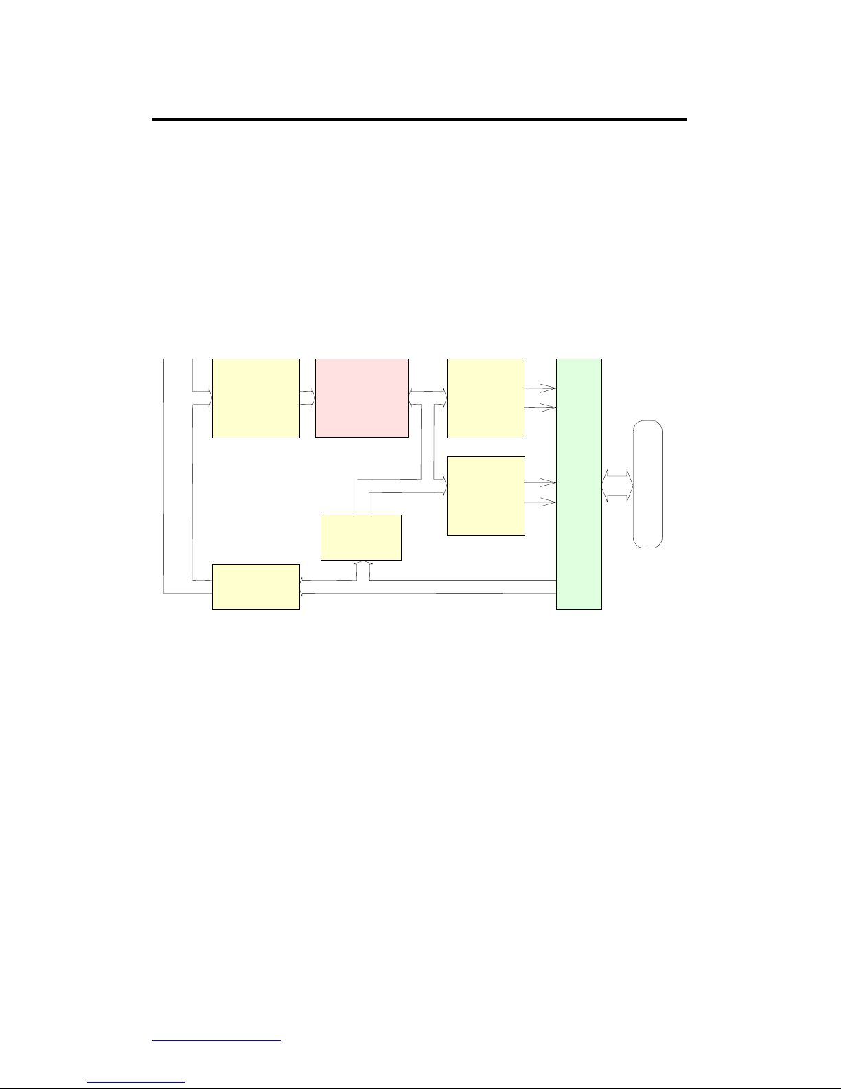
1.1 System Block Diagram
The I-8091 stepping motor control card is a micro-computer controlled, 2-axis
pulse generation card. It includes a 2Kbytes-FIFO to receive motion command
from host, a micro-computer for profile generation and protection, 2-axis DDA
chip to execute DDA function when interpolation command is used, 2500Vrms
optical isolation inserted for industrial application.
2K FIFO
Interface
CPU
DDA Chip
X-axis
DDA Chip
Y-axis
Optical
Isolation
Limit Switch
Input Port
Connector
Limit Switch Signal
Profile Generation
Protection
Limit Switch
Input Port
Bus
Fig.(1) block diagram of I-8091 card
http://www.icpdas.com 2-4 ICPDAS
I-8091 User Manual Version 2.0 04/2003
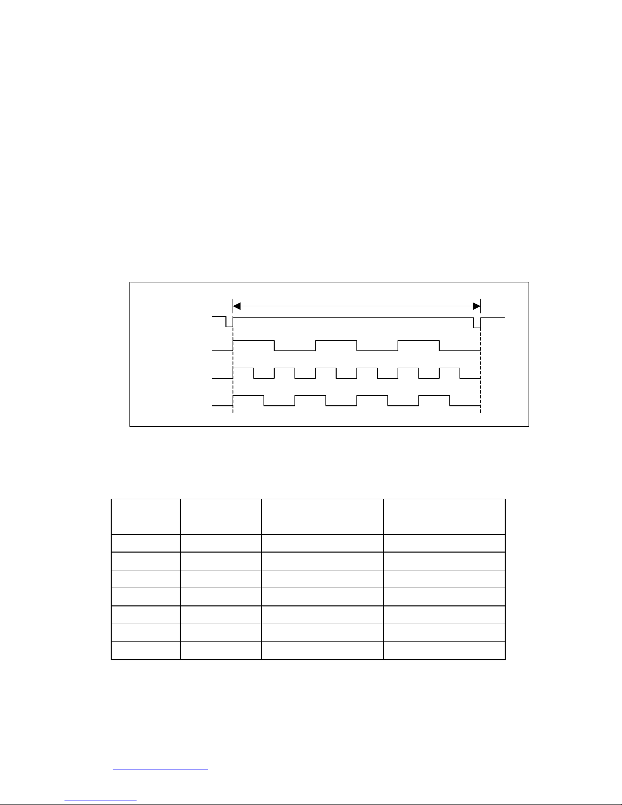
1.2 DDA Technology
The DDA chip is the heart of I-8091 card, it will generate equal-space
pulse train corresponding to specific pulse number during a DDA period.
This mechanism is very useful to execute pulse generation and
interpolation function. The DDA period can be determined by DDA cycle.
Table(1) shows the relation among DDA cycle, DDA period and output
pulse rate. When DDA cycle set to 1, the DDA period is equal to
(1+1)x1.024ms = 2.048ms. The output pulse number can be set to 0~2047,
therefore the maximum output pulse rate will be 1Mpps. The minimum
output pulse rate is 3.83pps when set DDA cycle=254 (DDA period =
(254+1)x1.024ms = 261.12ms).
DDA period
Z pulse = 4
Y pulse = 6
X pulse = 3
DDA cycle
Fig.(2) DDA mechanism
Table(1) The Relation among DDA cycle, DDA period and output pulse rate.
DDA cycle DDA period Max. pulse
rate(n=2047)
Min. pulse rate (n=1)
1 2.048ms 999511pps 488pps
2 3.072ms 666341pps 325pps
3 4.096ms . .
. . . .
N (N+1)*1.024ms 2047/(DDA period) 1/(DDA period)
. . . .
254 261.12ms 7839pps 3.83pps
The DDA cycle can be set by i8091_SET_VAR() command which decribed
in charpter 3. The selection criterion of DDA cycle was described as
following.
http://www.icpdas.com 2-5 ICPDAS

I-8091 User Manual Version 2.0 04/2003
(1) The required max. output pulse rate.
PRmax = Vmax*N/60
PRmax =
2047
1 1 024*.
DDAcycle ms
+
()
PRmax : max. output pulse rate.
Vmax : max. speed (rpm).
N : the pulse number of stepping motor per revolution.
(pulse/rev).
2. The required speed resolution.
The maximum output pulse number is Np(0~2047), therefore
the speed resolution is Vmax(max. speed)/Np. The DDA cycle
can be obtained by following equation.
PRmax =
N
p
DDAcycle ms
*.
+
1 1 024()
3. When choose large DDA cycle (DDA period), it will occur
vibration between different pulse input which generally can be
observed during acceleration or deceleration. So, the small
DDA cycle , the smooth acceleration/deceleration curve as long
as the speed resolution is acceptable.
Example: Stepping Motor
The specification of stepping motor is 500 pulse/rev, max. speed 500
rpm, speed resolution 2 rpm.
The required max. pulse rate
PRmax = 500 rpm*500/60 = 4166.67 pps
The maximum output pulse
Np = 500rpm/2rpm =250 pulse number
The DDA cycle can be calculated by follow equation
PRmax =
N
p
DDAcycle ms
*.
+
1 1 024()
4166.67 =
250
1 1 024*.
DDAcycle ms
+
()
DDA cycle = 58
http://www.icpdas.com 2-6 ICPDAS

I-8091 User Manual Version 2.0 04/2003
High Speed = 247 pulse (4166.67*58*0.001024)
The above results means that maximum speed is 500rpm when send
command i8091_SET_VAR(0, 58, 2, 2, 247) to I-8091 card.
Example: Pulse type input Servo Motor
The specification of servo motor is 8000 pulse/rev, max. speed 3000 rpm,
speed resolution 2 rpm.
The required max. pulse rate
PRmax = 3000 rpm*8000/60 = 400,000 pps
The maximum output pulse
Np = 3000rpm/2rpm =1500 pulse number
The DDA cycle can be calculated by follow equation
PRmax =
N
p
DDAcycle ms
*.
+
1 1 024()
400,000 =
1500
1 1 024*.
DDAcycle ms
+
()
DDA cycle = 3
High Speed = 1638 pulse (400,000*4*0.001024)
The above results means that maximum speed is 3000rpm when send
command i8091_SET_VAR(0, 3, 2, 2, 1638) to I-8091 card.
http://www.icpdas.com 2-7 ICPDAS
I-8091 User Manual Version 2.0 04/2003
2 Hardware
_
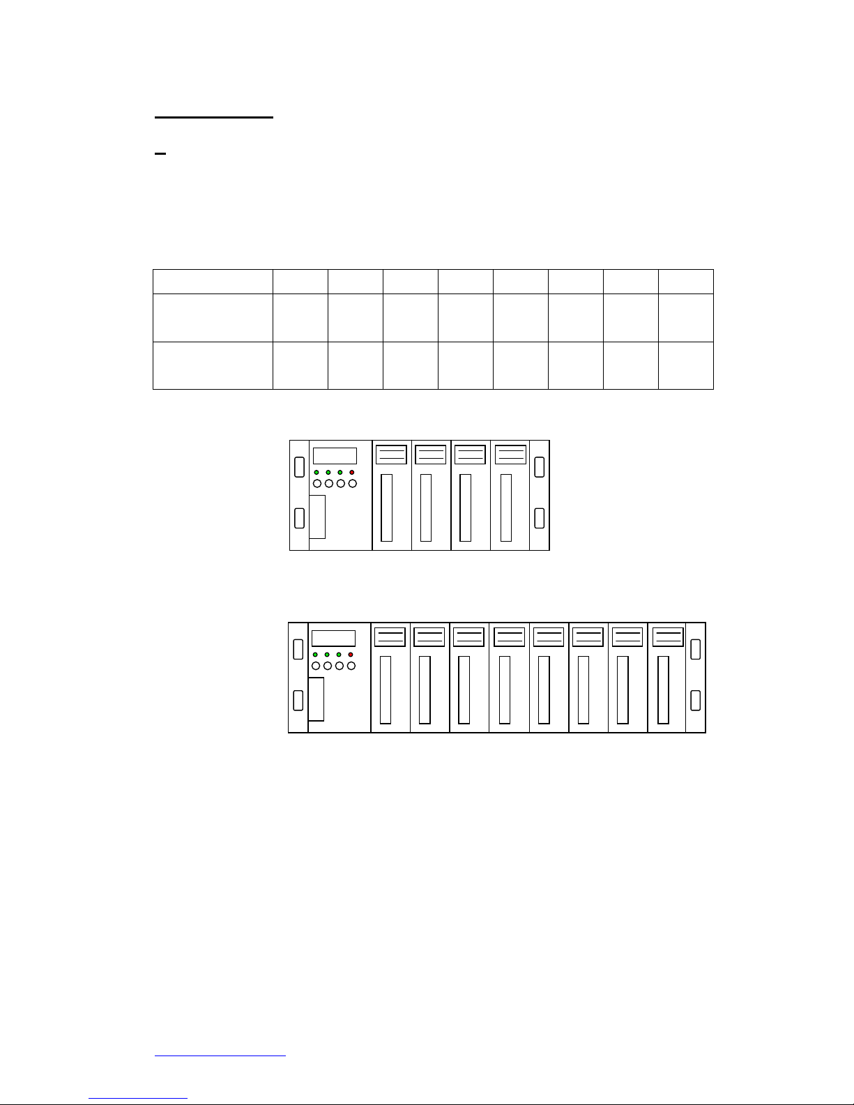
2.1 I-8000 hardware address
The hardware address of I-8000 main system is fixed as following table.
There are 4 slots I-8000 and 8 slots I-8000.
Slot 1 Slot 2 Slot 3 Slot 4 Slot 5 Slot 6 Slot 7 Slot 8
I-8000, 4 slot
address
0x080 0x0A0 0x0C0 0x0E0 --- --- --- ---
I-8000, 8 slot
address
0x080 0x0A0 0x0C0 0x0E0 0x140 0x160 0x180 0x1A0
Slot 1 Slot 2 Slot 3 Slot 4
Slot 8 Slot 7 Slot 6 Slot 5 Slot 4 Slot 3 Slot 2 Slot 1
88888
88888
I-8000, 4 slots
I-8000, 8 slots
Fig.(3) I-8000 hardware address
http://www.icpdas.com 2-8 ICPDAS
I-8091 User Manual Version 2.0 04/2003
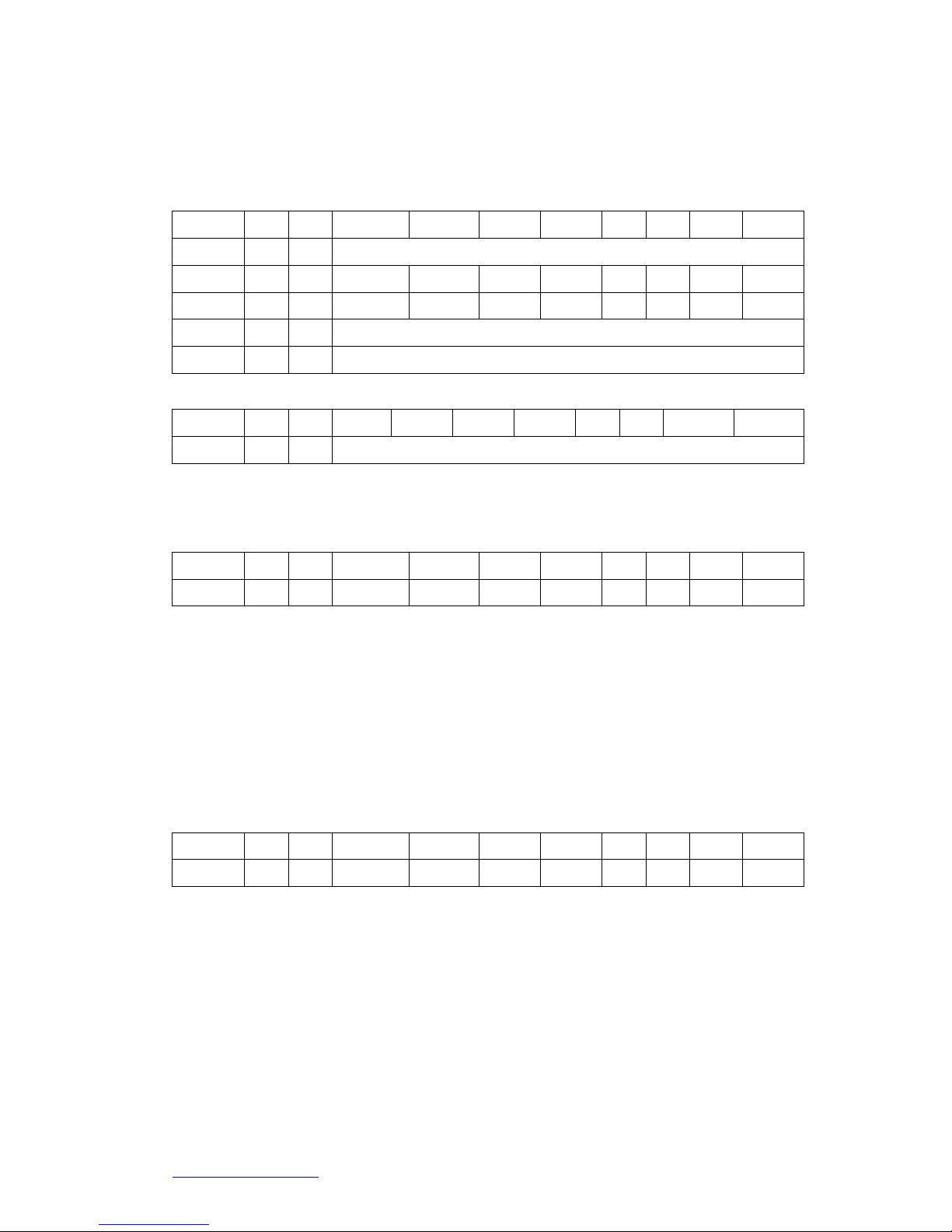
2.2 Registers of I-8091 board
The I-8091 card’s registers table as following.
Register Add. R/W Bit 7 Bit 6 Bit 5 Bit 4 Bit 3 Bit 2 Bit 1 Bit 0
ID 0x00 R 0x0E
LIMIT1 0x01 R /EMG /FFFF /FFEF /LS14 /LS11 /ORG1
LIMIT2 0x02 R /YSTOP /XSTOP /LS24 /LS21 /ORG2
WRFF 0x01 W Command port
RSTFF 0x02 W Reset FIFO
Register Add. R/W Bit 7 Bit 6 Bit 5 Bit 4 Bit 3 Bit 2 Bit 1 Bit 0
ID 0x00 R 0x0E
The ID register is read only and its value is fixed as 0x0E. User can check
this register to identify I-8091 card or not.
Register Add. R/W Bit 7 Bit 6 Bit 5 Bit 4 Bit 3 Bit 2 Bit 1 Bit 0
LIMIT1 0x01 R /EMG /FFFF /FFEF /LS14 /LS11 /ORG1
/ORG1 : original point limit switch of X-axis.
/LS11, /LS14 : limit switches of X-axis, which must be configured as chapter
2.4.1.
/EMG : emergency switch.
/FFEF : active low, indicate FIFO is empty.
/FFFF : active low, indicate FIFO is full.
Register Add. R/W Bit 7 Bit 6 Bit 5 Bit 4 Bit 3 Bit 2 Bit 1 Bit 0
LIMIT2 0x02 R /YSTOP /XSTOP /LS24 /LS21 /ORG2
/ORG2 : original point switch of Y-axis.
/LS21, /LS24 : limit switches of Y-axis, which must be configured as chapter
2.4.1.
/XSTOP, /YSTOP : These signals indicate the operating situation of X, Y axis
in CPU.
1 : busy, 0 : stop
The commands i8091_WAIT_X( ) and i8091_WAIT_Y( ) just to waiting for
http://www.icpdas.com 2-9 ICPDAS
I-8091 User Manual Version 2.0 04/2003
'/XSTOP' or '/YSTOP' signal become to '0'.
Register Add. R/W Bit 7 Bit 6 Bit 5 Bit 4 Bit 3 Bit 2 Bit 1 Bit 0
WRFF 0x01 W Command port
I-8091 driver will send motion command by way of this register. Please do not
use this register to write any thing, or I-8091 will not operate properly.
Register Add. R/W Bit 7 Bit 6 Bit 5 Bit 4 Bit 3 Bit 2 Bit 1 Bit 0
RSTFF 0x02 W Reset FIFO
This register is used to reset FIFO for clear all of commands pending in the
FIFO buffer.
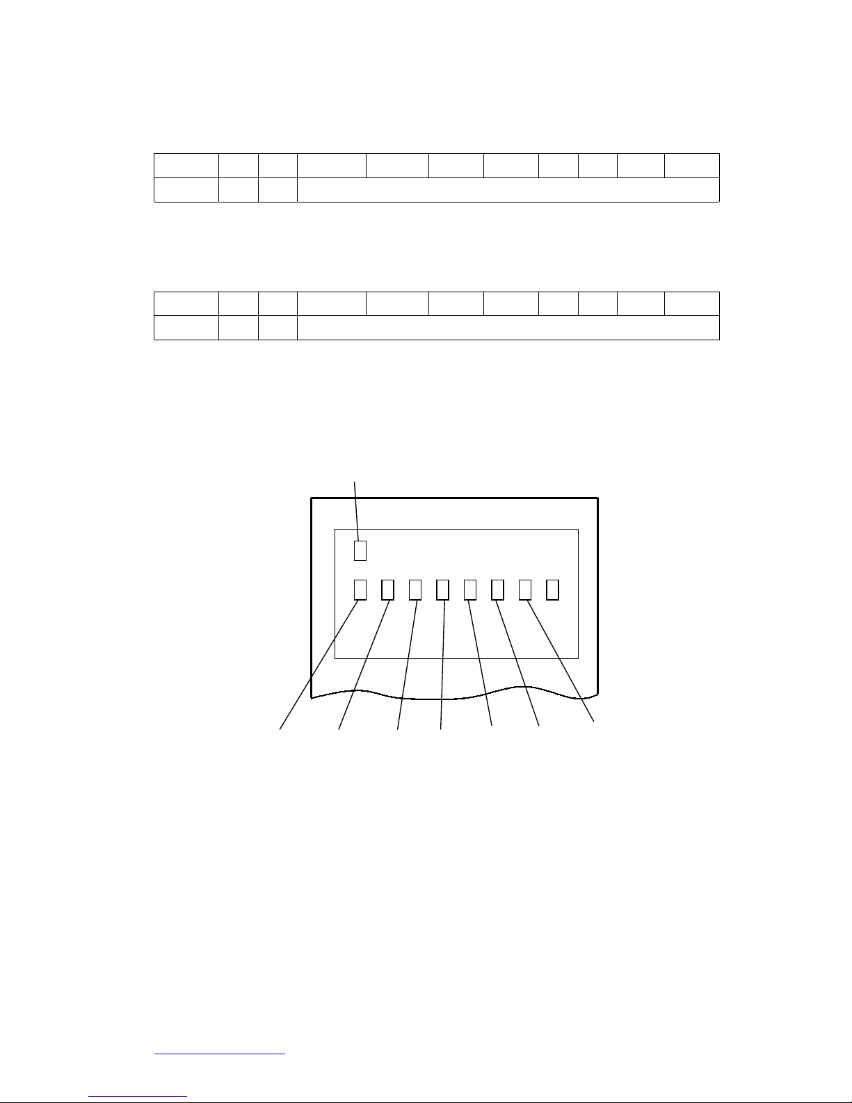
2.3 LED Indicator
power
/EMG
/LS21 /LS24 /ORG2 /LS14 /LS11
/ORG1
Fig.(4) I-8091 LED indicator
Where
/ORG1: X-axis’s original limit switch for machine home position.
/LS11, /LS14 : X-axis’s negative and positive limit switches.
/ORG2: Y-axis’s original limit switch for machine home position.
/LS21, /LS24 : Y-axis’s negative and positive limit switches.
/EMG : system’s emergency signal input.
http://www.icpdas.com 2-10 ICPDAS

I-8091 User Manual Version 2.0 04/2003
2.4 Hardware Configuration
2.4.1 Limit switch configuration
Because the profile generation and protection is executed by the CPU
on I-8091 card, the limit switches must configure as following diagram.
The motion command just can work properly.
LS11
ORG1
LS14
CW/FW
CCW/BW
Motor
EXT_GND
/LS11
/LS14
/ORG1
X axis
/EMG
Emergency
ccm
Fig.(5) Limit switch configuration of X axis
LS21
ORG2
LS24
CW/FW
CCW/BW
Motor
EXT_GND
/LS21
/LS24
/ORG2
Y axis
ccm
Fig.(6) Limit switch configuration of Y axis
http://www.icpdas.com 2-11 ICPDAS
I-8091 User Manual Version 2.0 04/2003
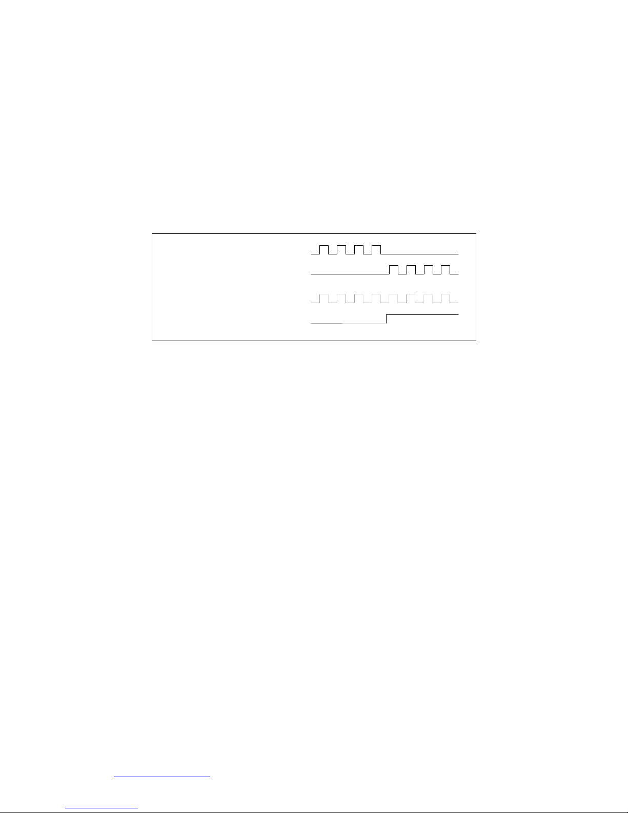
2.4.2 Output pulse mode configuration
I-8091 card provide two kind output method.
(a) CW/CCW mode
(b) Pulse/Direction mode
The command i8091_SET_MODE(cardNo, modeX, modeY) provide
parameters CW_CCW (0) and PULSE_DIR (1) to define output pulse
mode.
CW
CCW
Pulse
Direction
Mode = 1 (PULSE_DIR)
Mode = 0 (CW_CCW)
Fig.(7) Output pulse mode
2.4.3 Direction configuration
Sometimes, the output direction of X-axis, Y-axis is not in the
desired direction due to the motor’s connection or gear train. It is
recommended to unify the output direction as shown in Figure(5)(6). The
CW/FW direction is defined as toward outside from motor and the
CCW/BW direction is defined as toward inside to motor. The
i8091_SET_DEFDIR(cardNo, defdirX, defdirY) command provides
parameters NORMAL_DIR (0) and REVERSE_DIR (1) to define the
rotating direction of motor.
2.4.4 Turn Servo ON/OFF (Hold ON/OFF)
To turn servo motor into servo ON(OFF) state, or turn stepping motor
into hold ON(OFF) state, the command i8091_SET_SERVO_ON(cardNo,
sonX, sonY) provide parameters ON (1) and OFF (0) to turn ON or OFF.
2.4.5 Automatic protection
The I-8091 card has a automatic protected system.
(a) If X-aixs command is executing and moving toward CW/FW direction,
http://www.icpdas.com 2-12 ICPDAS
 Loading...