

I-8088W
API Reference Manual
Version 1.0.2, Oct. 2020
Service and usage information for Linux Platform
------------------------------------Written by Martin Hsu
Edited by Cindy Huang

Warranty
Warning
All products manufactured by ICP DAS are under warranty regarding
defective materials for a period of one year, beginning from the date of
delivery to the original purchaser.
ICP DAS assumes no liability for any damage resulting from the use of this
product. ICP DAS reserves the right to change this manual at any time
without notice. The information furnished by ICP DAS is believed to be
accurate and reliable. However, no responsibility is assumed by ICP DAS for
its use, not for any infringements of patents or other rights of third parties
resulting from its use.
Copyright
Copyright @ 2012 by ICP DAS Co., Ltd. All rights are reserved.
Trademark
The names used for identification only may be registered trademarks of
their respective companies.
Contact US
If you have any problem, please feel free to contact us.
You can count on us for quick response.
Email: service@icpdas.com
I-8088W API Reference Manual, Version 1.0.2, Oct. 2020 -- 2

Table of Contents
Table of Contents ................................................................................................................ 3
1. Introduction ................................................................................................................. 5
1.1. Specification ....................................................................................................... 6
1.2. Pin Assignment ................................................................................................... 7
1.3. Block Diagram .................................................................................................... 8
1.4. Wire Connection ................................................................................................. 9
2. Software and Getting Started ................................................................................... 10
2.1. Software ............................................................................................................10
2.2. Simple PWM Operation ..................................................................................... 11
2.2.1. Flow Chart ............................................................................................... 11
2.2.2. How to Setup the Standard PWM ...........................................................12
2.3. Using DI to Trigger PWM ...................................................................................16
2.3.1. Flow Chart ...............................................................................................16
2.3.2. How to Setup the Trigger PWM ............................................................... 17
2.4. Synchronize PWM .............................................................................................21
2.4.1. Flow Chart ...............................................................................................21
2.4.2. How to Setup the Standard PWM ...........................................................22
3. API for Linux PAC ...................................................................................................... 24
3.1.1. i8088W_Init .............................................................................................24
3.1.2. i8088W_GetFirmwareVersion .................................................................25
3.1.3. i8088W_GetLibVersion ...........................................................................26
3.1.4. i8088W_SetPWMDuty ............................................................................27
3.1.5. i8088W_SetPWMDuty_Deci ...................................................................28
3.1.6. i8088W_SetPWMDuty_float ....................................................................30
3.1.7. i8088W_GetRealPWMDuty_Deci ...........................................................32
3.1.8. i8088W_SetPWMCountMode .................................................................34
3.1.9. i8088W_SetBurstCount ...........................................................................36
3.1.10. i8088W_PWM_Start ...............................................................................37
3.1.11. i8088W_PWM_Stop ................................................................................38
3.1.12. i8088W_SetSyncChannel .......................................................................39
3.1.13. i8088W_GetSyncChannel .......................................................................41
I-8088W API Reference Manual, Version 1.0.2, Oct. 2020 -- 3

3.1.14. i8088W_Sync_Start ................................................................................42
3.1.15. i8088W_Sync_Stop ................................................................................43
3.1.16. i8088W_SetHardwareTrigChannel .........................................................44
3.1.17. i8088W_GetHardwareTrigChannel .........................................................46
3.1.18. i8088W_GetPWMActiveState .................................................................48
3.1.19. i8088W_GetDI ........................................................................................50
Appendix. Error Codes ..................................................................................................... 52
I-8088W API Reference Manual, Version 1.0.2, Oct. 2020 -- 4

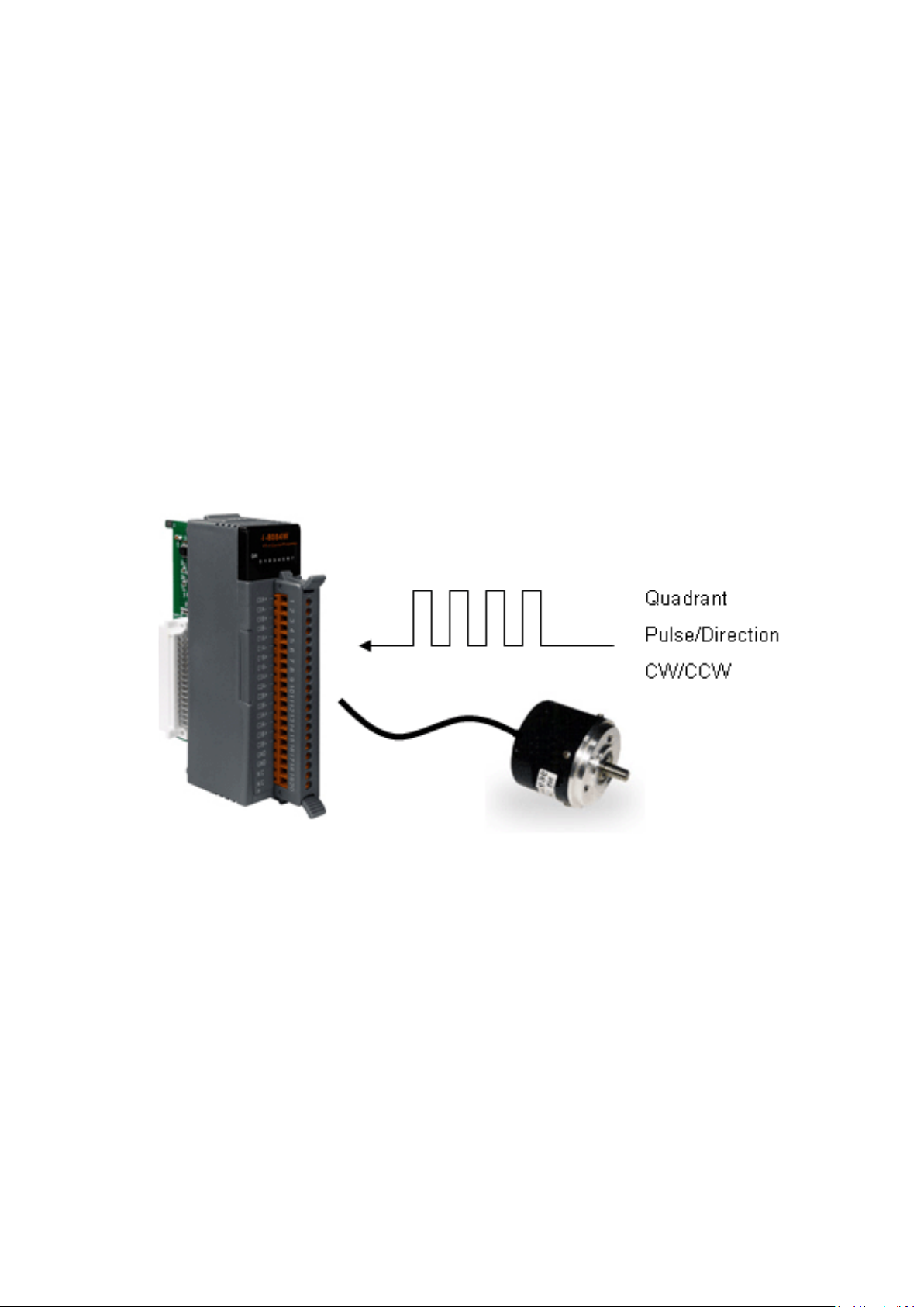
1. Introduction
PWM (Pulse width modulation) is a powerful technique for controlling analog circuits. It uses
digital outputs to generate a waveform with variant duty cycle and frequency to control
analog circuits. I-8088W has 8 PWM output channels and 8 digital inputs. It can be used to
develop powerful and cost effective analog control system.
Features:
Automatic generation of PWM outputs by hardware, without software intervention.
10 Hz ~ 500 kHz (non-continuous) PWM output frequency with 0.1% ~ 99.9% duty cycle
Software and hardware trigger mode for PWM output
Individual and synchronous PWM output Using software trigger mode, you can set
configuration for all PWM channels then trigger them one by one or all of them at the
same time.
Burst mode PWM operation for standby
DI channel can be configured as simple digital input channel or hardware trigger source
of the PWM output.
I-8088W API Reference Manual, Version 1.0.2, Oct. 2020 -- 5

1.1. Specification
PWM Output
Channels
8
Scaling Resolution
16-bit (1 ~ 128 µs for each step)
Frequency Range
10 Hz ~ 500 kHz (non-continuous)
Duty Cycle
0.1 % ~ 99.9 %
PWM Mode
Burst counting, Continuous mode
Burst Counter
1 ~ 65535
Hardware Trigger Mode
Trigger Start and Trigger Stop
Output Type
Source
Max. Load Current
1 mA
Intra-module Isolation, Field to Logic
3,750 Vrms
ESD Protection
4 kV Contact for each channel
Digital Input
Input Channels
8 (Sink/Source)
Input Type
One common for all digital input
On Voltage Level
+5 V ~ +30 V
Off Voltage Level
< 0.8 V
Input Impedance
4.7 kΩ, 1/4 W
Intra-module Isolation, Field to Logic
3,750 Vrms
ESD Protection
4 kV Contact for each channel
LED Display
1 LED as Power Indicator/16 LED as PWM and Digital Input Indicator
Power
Power Consumption
40 mA @ 5 V, 2 W ± 5 %
Environment
Operating Temperature
-25 °C ~ +75 °C
Storage Temperature
-30 °C ~ +85 °C
Humidity
5 % ~ 95 % RH, non-condensing
Dimensions
30 mm x 102 mm x 115 mm (W x L x H)
I-8088W API Reference Manual, Version 1.0.2, Oct. 2020 -- 6
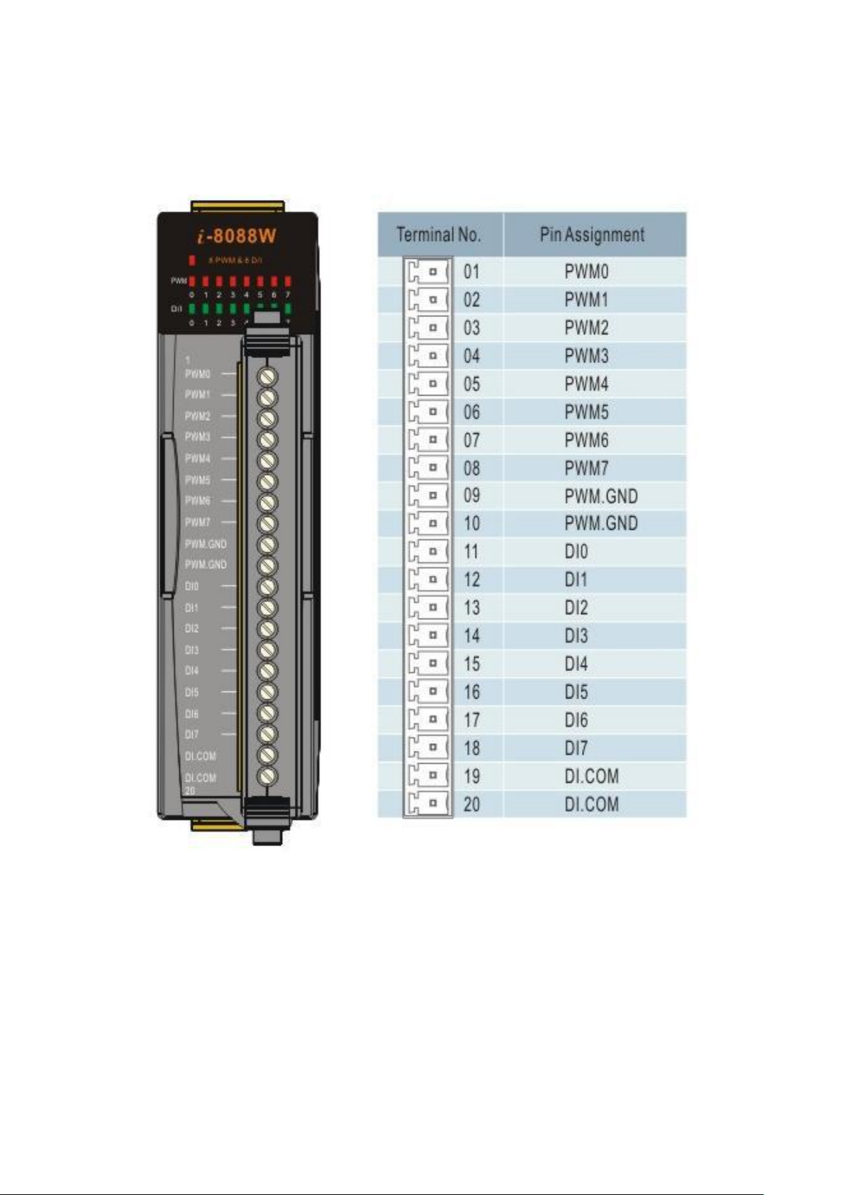
1.2. Pin Assignment
Pin 01 ~ 08: PWM0 ~ PWM7, are designed for PWM output
Pin 09 ~ 10: PWM.GND is isolated ground.
Pin 11 ~ 18: DI0 ~ DI7 are designed for digital input that also capable of setting as an
external trigger signal to start or stop its PWM pulse.
Pin 19 ~ 20: DI.COM is isolated ground.
I-8088W API Reference Manual, Version 1.0.2, Oct. 2020 -- 7
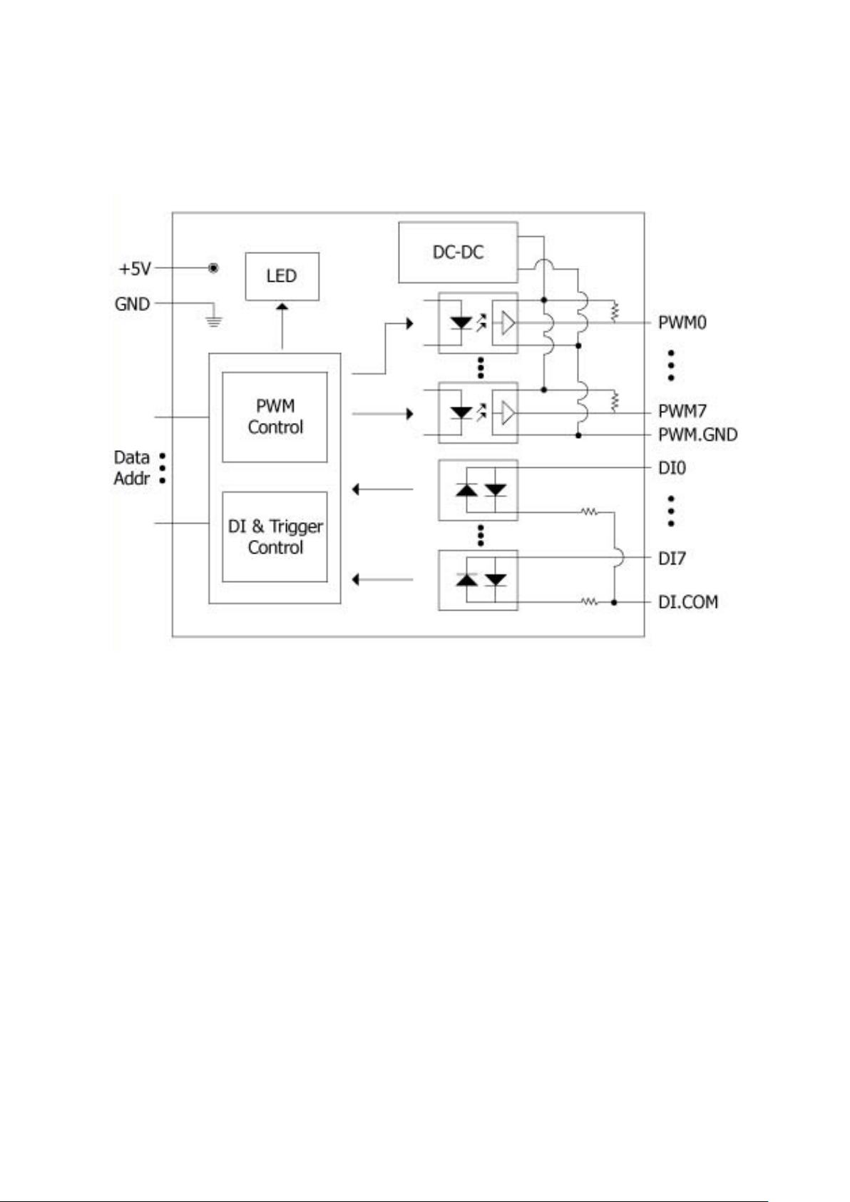
1.3. Block Diagram
I-8088W API Reference Manual, Version 1.0.2, Oct. 2020 -- 8
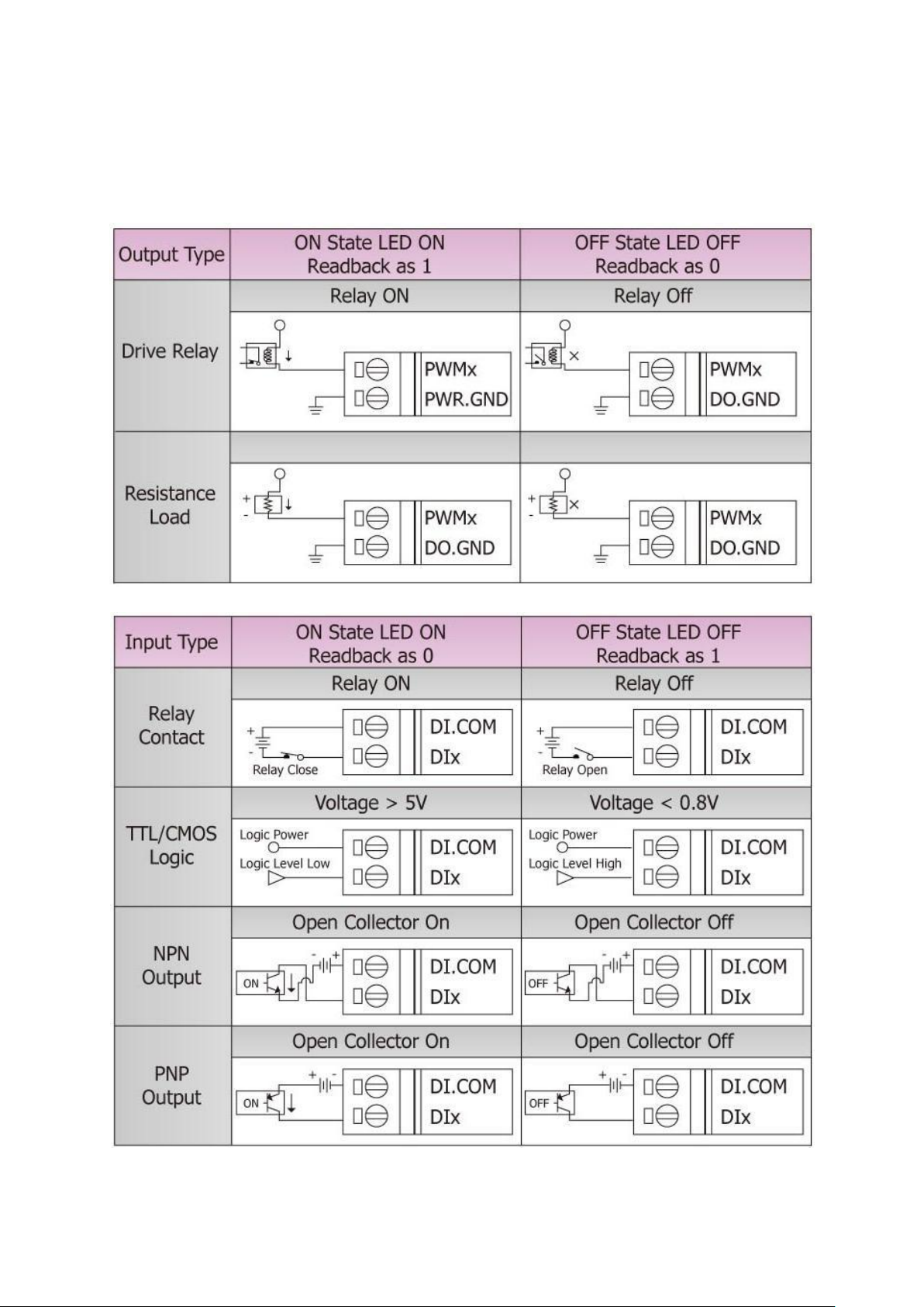
1.4. Wire Connection
I-8088W API Reference Manual, Version 1.0.2, Oct. 2020 -- 9
2. Software and Getting Started
PRRODUCT
CPU
DOWNLOAD LINK
LP-8x4x
PXA270
http://www.icpdas.com/en/download/show.php?num=982&model=LP-8441-EN
LP-8x2x/9x2x
AM335x
http://www.icpdas.com/en/download/show.php?num=915&model=LP-8421
LX-8000/9000
x86/E38xx
http://www.icpdas.com/en/download/show.php?num=904&model=LX-9381
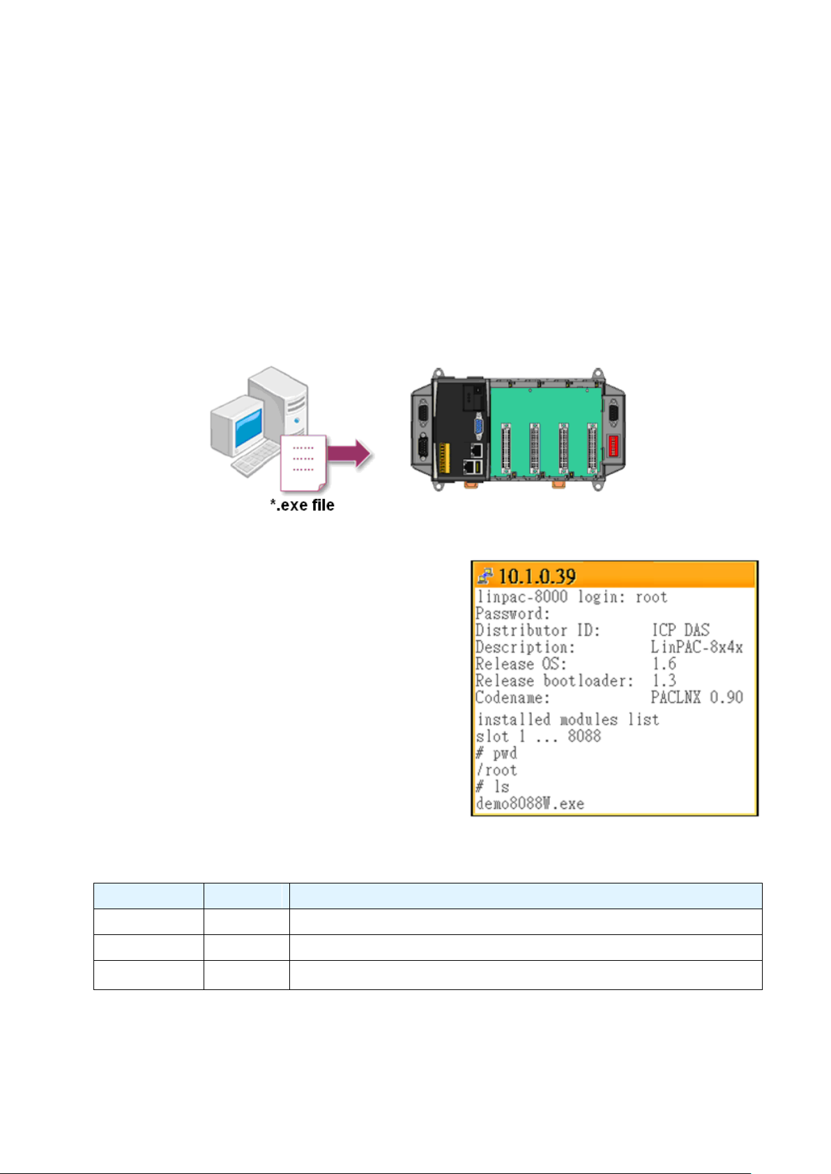
2.1. Software
In this section, we will introduce you one simple program (demo 8080W.exe) which have
three setup modes – Normal, Hardware Trigger and Synchronize. We need to check the
following steps before running the program.
1. First, user need to download LinPAC SDK,
which is includes GNU toolchain, Libraries,
header, examples files, etc.
2. Check the power cable, Ethernet cable, VGA
monitor, the communication cable between
controller and PC has been connected well,
and then check the i-8088W has been plugged
in the controller.
3. Next, check the communication between
controller and PC is fine, and download the
demo program files to the controller.
4. User can find the related files in the product CD or below website:
I-8088W API Reference Manual, Version 1.0.2, Oct. 2020 -- 10
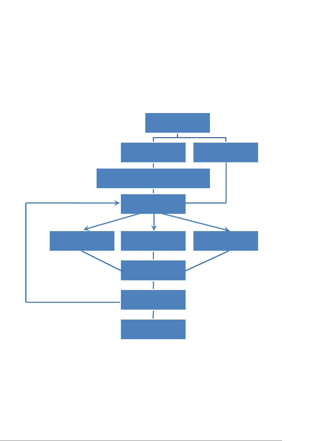
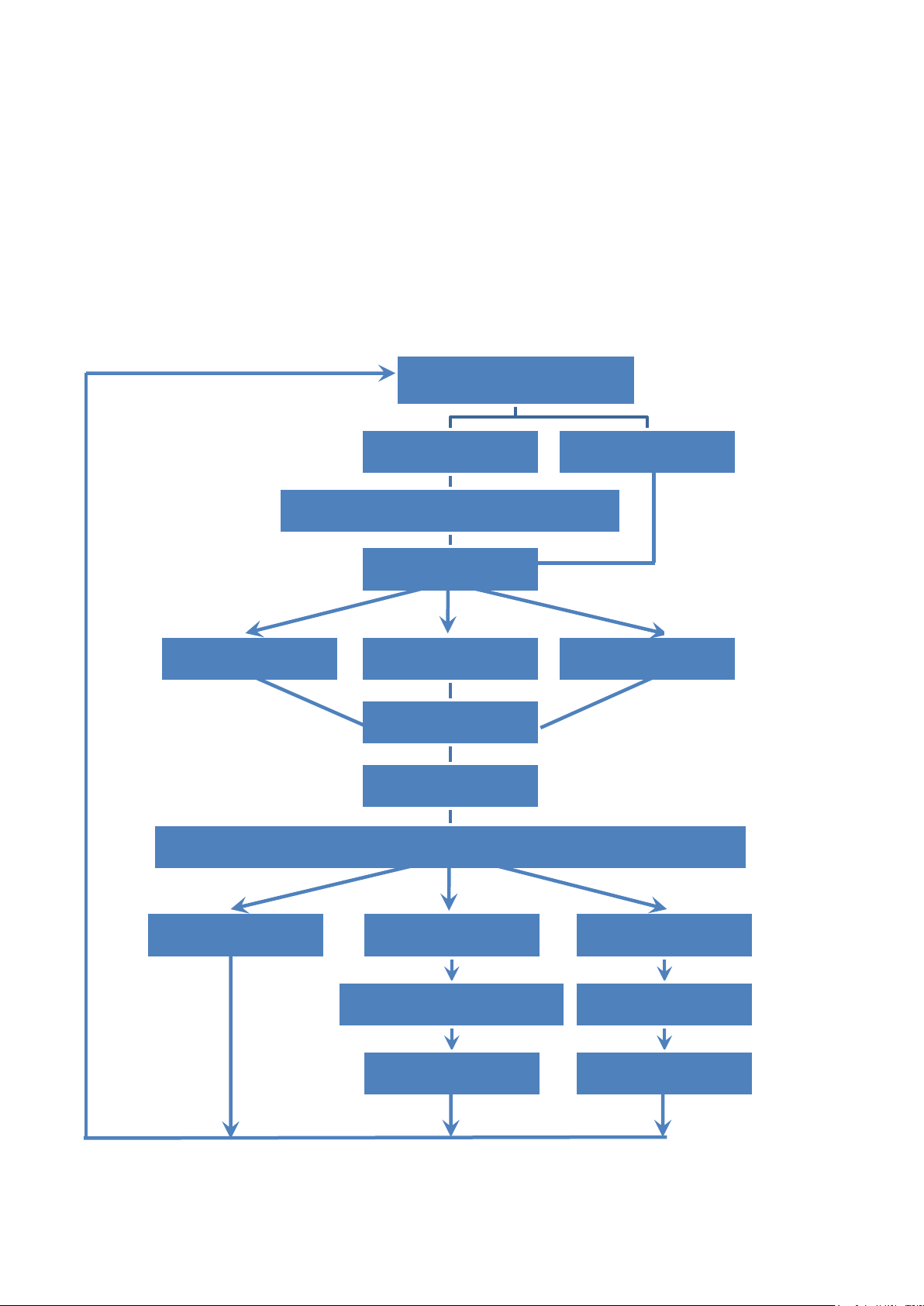
2.2. Simple PWM Operation
Set PWM Mode
Set Burst Count
Choice Burst Count Mode (1 -65535)
Set PWM Duty
(Frequency and Duty)
Set Integer Duty Set x10 Integer Duty
Start or Stop PWM
Start PWM
Stop PWM
Set Float Duty
Set Continous
0
1
0
1
2
Frequency:
Select 0: 1 – 00000 Hz
Select 1: 1 – 500000 Hz
Select 2: 0.1 – 500000.0 Hz
Duty:
Select 0: 1 – 99 %
Select 1: 1 – 99 %
Select 2: 0.1 – 99.9 %
Note: Each time you change the settings of “PWM Duty", you have to re-send the
“Start PWM” command to ensure the operation properly.
2.2.1. Flow Chart
I-8088W API Reference Manual, Version 1.0.2, Oct. 2020 -- 11
2.2.2. How to Setup the Standard PWM
Please make sure you have completed the steps in section 2.1 before operating the
following steps.
Description of the demo:
In this example, we will use the demo to set I-8088W as “Continuous” mode and its
frequency is 10 Hz, PWM duty is 50%. When we send the “Start Normal PWM” commend,
the DI0 will blinking per 0.5s.
Wire connection of I-8088W:
To do this, you need to wire PW0 to DI0, DI.COM to External 5V, PWM.GND to External
GND. (Please refer to section 1.2 Pin Assignment)
Now, follow the steps to configure the related parameter:
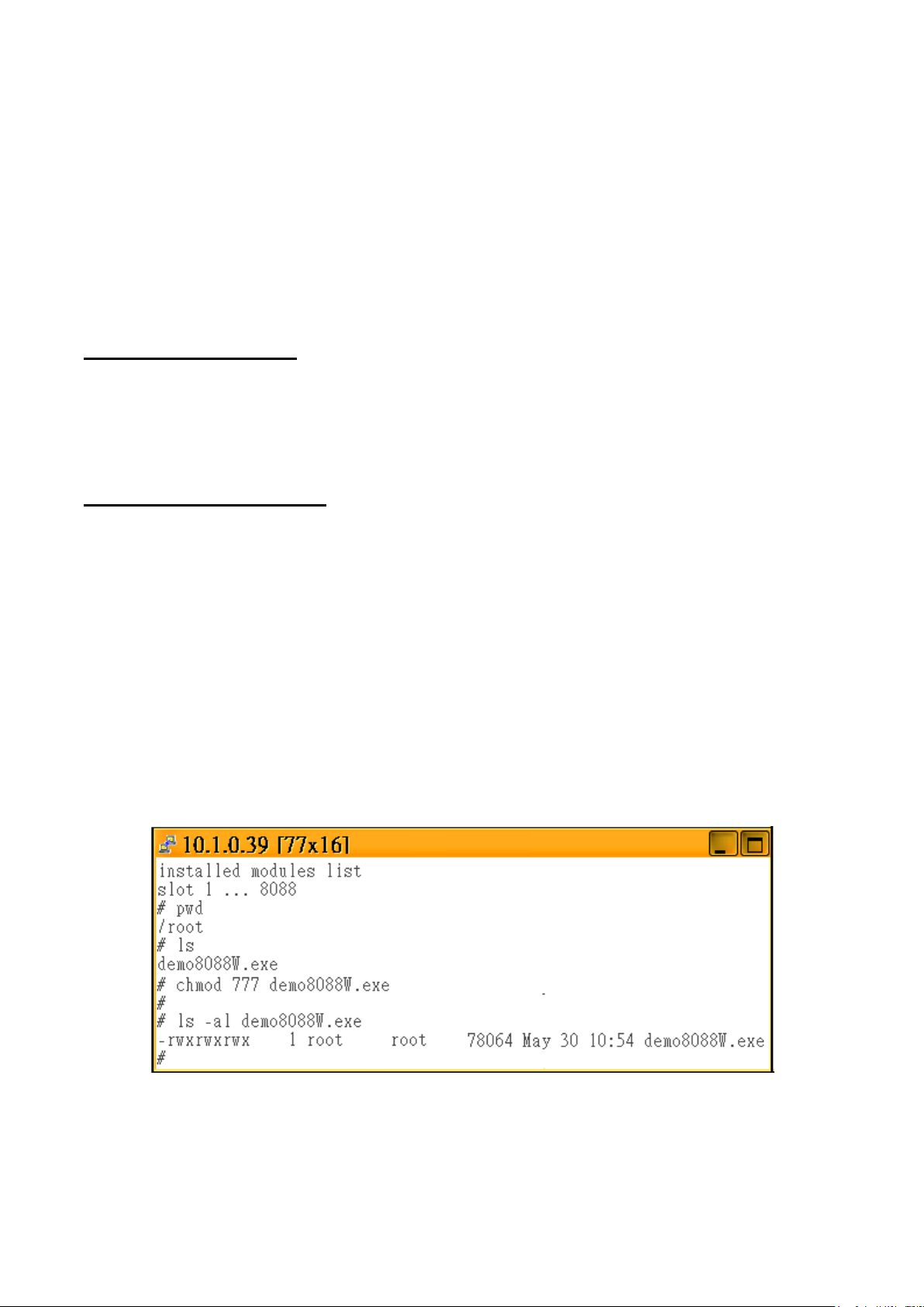
Step 1: Change the authority of “demo8088W.exe”
For example, my LP-8x4x’s IP address is 10.1.0.39, and telnet to the LP-8x4x by pietty.exe
as below:
I-8088W API Reference Manual, Version 1.0.2, Oct. 2020 -- 12
Step 2: Change the authority of “demo8088W.exe”
When you run the program, it will initialize the i-8088W module and obtain the related
information as shown below.
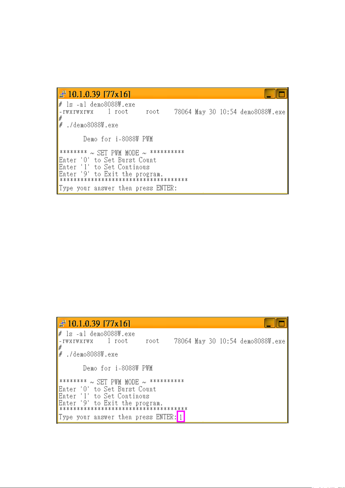
Step3: Set PWM Mode
This setting includes two modes – “Burst Count Mode” and “Continuous Mode”.
“Burst Count Mode” means it can output multiple fixed pulse in a period time and then stop
output. “Continuous Mode” means it can output one fixed pulse in a period time and continue
output.
In this example, we enter "1" to set it as "Continuous mode".
I-8088W API Reference Manual, Version 1.0.2, Oct. 2020 -- 13
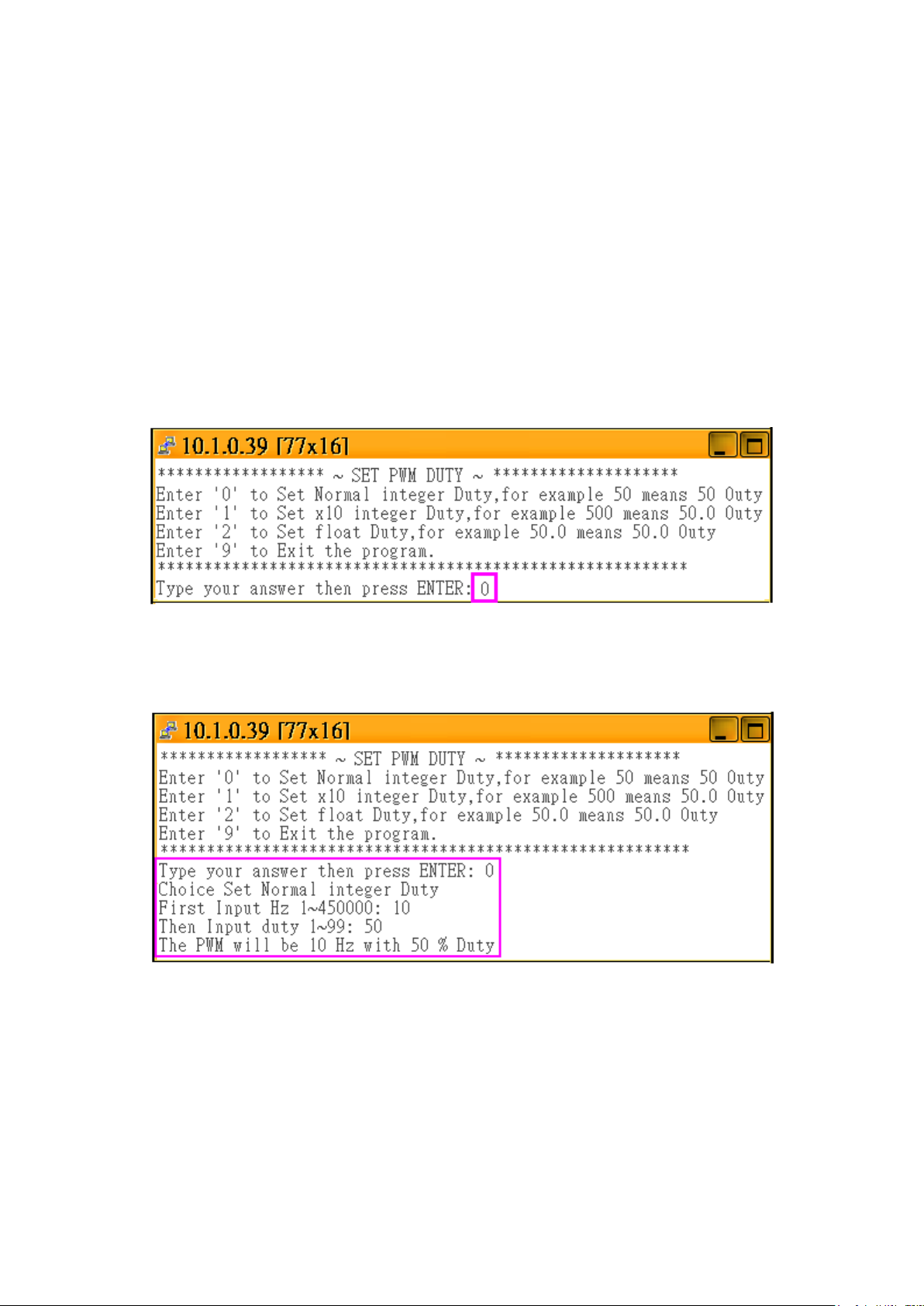
Step 4: Set PWM Duty
There are three options in this setting, if you choose:
"0" means you can enter an integer value (ex. input 50 to set it as 50 %)
"1" means you can enter an integer value to set it as one decimal place value. (ex. input
999 to set it as 99.9 %)
"2" means you can enter a one decimal place value. (ex. input 99.9 to set it as 99.9 %)
In this example, please enter "0" to set it as “Normal integer Duty”
Then, we will set its frequency as 10 Hz, PWM duty as 50 %.
I-8088W API Reference Manual, Version 1.0.2, Oct. 2020 -- 14
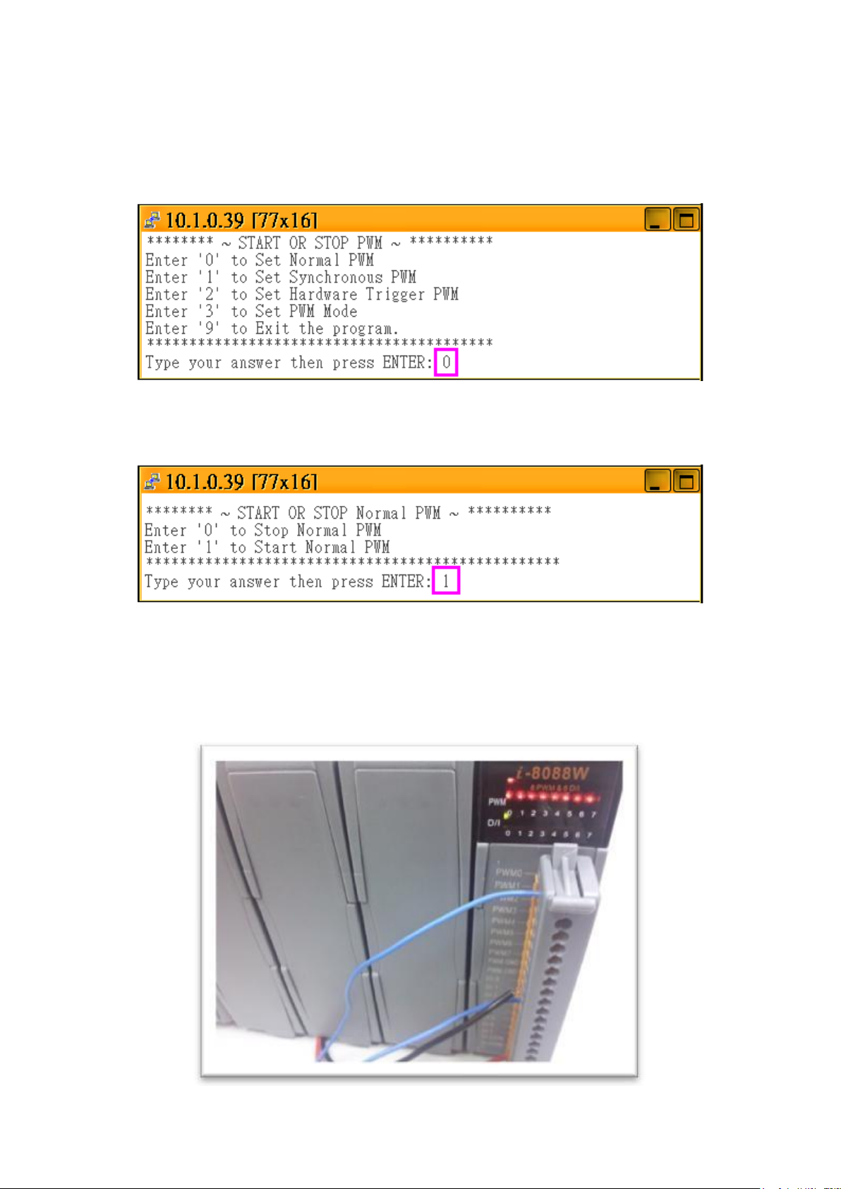
Step 5: Start PWM
You will see three modes in below picture, please enter “0” to set it as “Normal PWM”
Then enter “0” to start the PWM.
If you have completed the correct setup, you will see below picture. In this example, it will
send the “start PWM“ command to channel 0 ~ 7, the condition is 10 Hz with 50% duty, and
we has connected the PWM0 to DI0, so the DI0 will blink per 0.5 seconds.
I-8088W API Reference Manual, Version 1.0.2, Oct. 2020 -- 15
2.3. Using DI to Trigger PWM
Set PWM Mode
Set Burst Count
Choice Burst Count Mode (1~65535)
Set PWM Duty
Set Integer Duty Set x10 Integer Duty
Input Frequency
Input Duty
Configure DI as external trigger source for each channel
Set DI as Normal
PWM
DI signal to Start
PWM
Wait DI signal to Start PWM
Stop PWM
DI signal to Stop
PWM
Start PWM
Wait DI signal to Stop
PWM
Set Float Duty
Set Continous
0 1 0
1
2 0 1
2
Frequency:
Select 0: 1 ~ 00000 Hz
Select 1: 1 ~ 500000 Hz
Select 2: 0.1 ~ 500000.0 Hz
Duty:
Select 0: 1 ~ 99 %
Select 1: 1 ~ 99 %
Select 2: 0.1 ~ 99.9 %
2.3.1. Flow Chart
I-8088W API Reference Manual, Version 1.0.2, Oct. 2020 -- 16

2.3.2. How to Setup the Trigger PWM
There are 8 DI pins on I-8088W, normally these DI pin just acts as digital input channels. We
can also configure them as external trigger signal pins to start or stop the PWM output.
Step 1: Follow the same way in section 2.2.2 to configure PWM output mode and set
PWM duty and frequency.
Step 2: Enter “1” to set “Hardware Trigger PWM”
There are three options to set the DI channels as PWM trigger signal:
“0”: Normal DI. If you set it as "Normal DI" mode, it will be unrelated to the PWM
function.
“1”: Accept DI signal to start the PWM output.
“2”: Accept DI signal to stop the PWM output.
I-8088W API Reference Manual, Version 1.0.2, Oct. 2020 -- 17
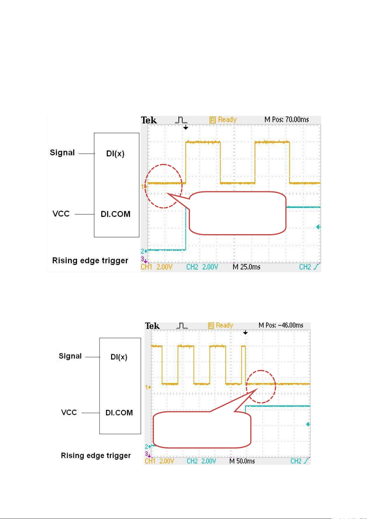
There are two ways to configure the DI signal to start or stop the PWM output. One is rising
“Rising edge” to trigger
the PWM to START.
“Rising edge” to trigger
the PWM to STOP.
edge to trigger the PWM to start or stop, the wiring like below two pictures.
Rising edge to Start PWM
Rising edge to Stop PWM
I-8088W API Reference Manual, Version 1.0.2, Oct. 2020 -- 18

“Falling edge” to
trigger the PWM to
START.
“Falling edge” to trigger
the PWM to STOP.
The other is falling edge to trigger the PWM to start or stop, the wiring like below two
pictures.
Falling edge to Start PWM
Falling edge to Stop PWM
I-8088W API Reference Manual, Version 1.0.2, Oct. 2020 -- 19

Step 3: Start the PWM
You can enter “1” to start the PWM output. It will start PWM when received an external
trigger signal.
Step 4: Stop the PWM:
In Normal PWM mode, the signal will continue transfer until you go back to enter “2” to stop
the PWM output.
I-8088W API Reference Manual, Version 1.0.2, Oct. 2020 -- 20

2.4. Synchronize PWM
Set PWM Mode
Set Burst Count
Choice Burst Count Mode (1 -65535)
Set PWM Duty
Set Integer Duty
Set x10 Integer Duty
Input Frequency
Input Duty
Enable Synchronous PWM for each channel
Start PWM
Synchronous Start PWM
Stop PWM
Set Float Duty
Set Continous
0
1
0
1
2
Frequency:
Select 0: 1 ~ 00000 Hz
Select 1: 1 ~ 500000 Hz
Select 2: 0.1 ~ 500000.0 Hz
Duty:
Select 0: 1 ~ 99 %
Select 1: 1 ~ 99 %
Select 2: 0.1 ~ 99.9 %
2.4.1. Flow Chart
I-8088W API Reference Manual, Version 1.0.2, Oct. 2020 -- 21
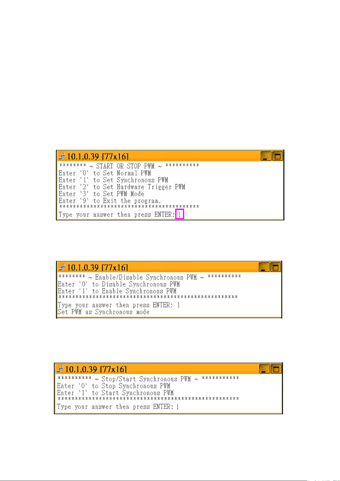
2.4.2. How to Setup the Standard PWM
I-8088W can configure each PWM output channel as synchronous mode.
Step 1: Follow the same way in section 2.2.2 to configure PWM output mode and set
PWM duty and frequency.
Step 2: Enter “2” to set “Synchronous PWM”
Step 3: Enter“1” to enable
Step 4: Enter“1” to start Synchronous PWM.
I-8088W API Reference Manual, Version 1.0.2, Oct. 2020 -- 22

You will see the different between following two pictures.
Non-synchronous
Synchronous
Start PWM:
In previous sections, we can start PWM by software command or DI trigger signal, but you
can see the signal is non-synchronous in below picture.
Start Synchronous PWM:
So, we can call i8088W_Sync_Start or pac_i8088W_Sync_Start to start the PWM output
and synchronize the rising edge for each synchronous PWM pulse.
I-8088W API Reference Manual, Version 1.0.2, Oct. 2020 -- 23

3. API for Linux PAC
3.1.1. i8088W_Init
The function can initialize the I-8088W and then check the hardware ID for each slot. If the return
value is “0” that means there is an I-8088W module in that slot. If return “-1” that means there is
no I-8088W module.
Syntax
short i8088W_Init(int slot);
Parameters
slot: 1 ~ 8
Return Value
Please refer to Error Code Table.
Example
[C]
int slotIndex, err;
err=i8088W_Init(slotIndex);
Open_Slot(slotIndex);
if(err==0)
printf(“There is an I-8088W at slot %d\n”,slotIndex);
else
printf(“There is no I-8088W at slot %d\n”,slotIndex);
I-8088W API Reference Manual, Version 1.0.2, Oct. 2020 -- 24

3.1.2. i8088W_GetFirmwareVersion
The function is used to get the firmware version of I-8088W.
Syntax
short i8088W_GetFirmwareVersion(int slot);
Parameters
slot: 1 ~ 8
Return Value
The firmware version of I-8088W hardware.
Example
[C]
short firmware_version;
Open_Slot(slot);
firmware_version = i8088W_GetFirmwareVersion(int slot);
I-8088W API Reference Manual, Version 1.0.2, Oct. 2020 -- 25

3.1.3. i8088W_GetLibVersion
The function is used to get the version of library file.
Syntax
short i8088W_GetLibVersion(void);
Parameters
None
Return Value
The versions of library file.
Example
[C]
short version;
Open_Slot(slot);
version = i8088W_GetLibVersion();
I-8088W API Reference Manual, Version 1.0.2, Oct. 2020 -- 26

3.1.4. i8088W_SetPWMDuty
The function is used to set the related PWM parameters.
Syntax
short i8088W_SetPWMDuty(int slot,int ch,unsigned long hz,unsigned int duty);
Parameters
slot: 1 ~ 8
ch: 0 ~ 7
hz: 0 ~ 450K
duty High part: 0 ~ 99
Low part: 100 - High part
Return Value
Please refer to Error Code Table.
Example
[C]
int ch, slot = 1;
Open_Slot(slot);
for(ch=0;ch<8;ch++)
{
i8088W_ SetPWMDuty (slot, ch, 50);
}
I-8088W API Reference Manual, Version 1.0.2, Oct. 2020 -- 27

3.1.5. i8088W_SetPWMDuty_Deci
The function is used to set the PWM parameters precisely.
Syntax
short i8088W_SetPWMDuty_Deci (int slot,int ch,unsigned long deci_Hz,unsigned
int deci_duty);
Note
i8088W_SetPWMDuty_Deci is the same as i8088W_SetPWMDuty_float in usage,
but the i8088W_SetPWMDuty_Deci will run faster than i8088W_SetPWMDuty_floa
for the floating calculation reason
Parameters
slot: 1 ~ 8
ch: 0 ~ 7
deci_Hz example: 10 deci_Hz = 10 Hz
deci_duty 0~999, for example: 503 deci_duty = 50.3% High Part
Low Part=1000 - 503= 497 => 49.7% Low Duty cycle
Return Value
Please refer to Error Code Table.
I-8088W API Reference Manual, Version 1.0.2, Oct. 2020 -- 28

Example
[C]
int slot,ch;
slot = 1;
Open_Slot(slot);
for(ch=0;ch<8;ch++)
{
i8088W_ SetPWMDuty_Deci(slot,ch,50.3);
}
I-8088W API Reference Manual, Version 1.0.2, Oct. 2020 -- 29

3.1.6. i8088W_SetPWMDuty_float
The function is used to set the PWM parameters precisely
Syntax
short i8088W_SetPWMDuty_Float(int slot,int ch,float f_Hz,float f_Duty);
Note
i8088W_SetPWMDuty_Deci is the same as i8088W_SetPWMDuty_float in usage,
but the i8088W_SetPWMDuty_Deci will run faster than i8088W_SetPWMDuty_floa
for the floating calculation reason
Parameters
slot: 1 ~ 8
ch: 0 ~ 7
f_Hz 100 means f_Hz = 10 Hz
f_Duty 0.0~99.9, for example: 50.3 means 50.3% High Part
Low Part =100.0- f_Duty = 49.7 means = 49.7%
Return Value
Please refer to Error Code Table.
I-8088W API Reference Manual, Version 1.0.2, Oct. 2020 -- 30

Example
[C]
int slot,ch;
slot = 1;
Open_Slot(slot);
for(ch=0;ch<8;ch++)
{
i8088W_ SetPWMDuty_Float (slot,ch,50.3);
}
I-8088W API Reference Manual, Version 1.0.2, Oct. 2020 -- 31

3.1.7. i8088W_GetRealPWMDuty_Deci
The function will get real frequency and duty that can be produced by 8088W.
Syntax
short i8088W_GetRealPWMDuty_Deci (int slot,int ch,unsigned long*
deci_hz,unsigned int* deci_duty);
Note
The duty and frequency of 8088W PWM is discrete not continuous,when we use
i8088W_SetPWMDuty to configure the duty and frequency, we have to use this function
to check the real duty and frequency which can be produced by 8088W normally, at low
frequency 10K, the configued frequency will be closer to real frequcncy can be
generated.
Parameters
slot: 1 ~ 8
ch: 0 ~ 7
deci_hz: the real frequency produced by 8088W unit (x10Hz)
deci_duty: the real duty produced by 8088W (x10 %)
Return Value
Please refer to Error Code Table.
I-8088W API Reference Manual, Version 1.0.2, Oct. 2020 -- 32

Example
[C]
unsigned long deci_hz;
unsigned int deci_duty
slot = 1;
Open_Slot(slot);
for(ch=0;ch<8;ch++)
{
i8088W_GetRealPWMDuty_Deci(slot,ch,& deci_hz, & deci_duty);
printf(“CH[%d] PWM Hz = %lu ; Duty = %u\n”, ch, deci_hz, deci_duty);
}
I-8088W API Reference Manual, Version 1.0.2, Oct. 2020 -- 33

3.1.8. i8088W_SetPWMCountMode
The function is used to set the count mode of I-8088W.
Syntax
short i8088W_SetPWMCountMode(int slot,int ch,unsigned char countMode);
Parameters
slot: 1 ~ 8
ch: 0 ~ 7
count Mode
1: Continuos
0: Burst count
Return Value
Please refer to Error Code Table.
I-8088W API Reference Manual, Version 1.0.2, Oct. 2020 -- 34

Example
[C]
int slot,ch;
slot = 1;
mode=0; //burst mode
Open_Slot(slot);
for(ch=0;ch<8;ch++)
{
i8088W_ SetPWMCountMode(slot,ch,mode);
}
I-8088W API Reference Manual, Version 1.0.2, Oct. 2020 -- 35

3.1.9. i8088W_SetBurstCount
The function is used to set the BurstCount of I-8088W.
Syntax
short i8088W_SetBurstCount(int slot,int ch,unsigned int burstCount);
Parameters
slot: 1 ~ 8
ch: 0 ~ 7
burstCount: 0~65536
Return Value
Please refer to Error Code Table.
Example
[C]
int slot=1, ch, burstCount=10000;
Open_Slot(slot);
for(ch=0;ch<8;ch++)
{
i8088W_ SetBurstCount (slot, ch, burstCount);
}
I-8088W API Reference Manual, Version 1.0.2, Oct. 2020 -- 36

3.1.10. i8088W_PWM_Start
The function is used to start the PWM pulse.
Syntax
short i8088W_PWM_Start(int slot,int ch);
Parameters
slot: 1 ~ 8
ch: 0 ~ 7
Return Value
Please refer to Error Code Table.
Example
[C]
int slot,ch;
slot = 1;
Open_Slot(slot);
for(ch=0;ch<8;ch++)
{
i8088W_PWM_Start (slot,ch);
}
I-8088W API Reference Manual, Version 1.0.2, Oct. 2020 -- 37

3.1.11. i8088W_PWM_Stop
The function is used to stop the PWM pulse.
Syntax
short i8088W_PWM_Stop(int slot,int ch);
Parameters
slot: 1 ~ 8
ch: 0 ~ 7
Return Value
Please refer to Error Code Table.
Example
[C]
int slot=1, ch;
Open_Slot(slot);
for(ch=0;ch<8;ch++)
{
i8088W_PWM_Stop(slot, ch);
}
I-8088W API Reference Manual, Version 1.0.2, Oct. 2020 -- 38

3.1.12. i8088W_SetSyncChannel
The function is used to set the specific channel as synchronous.
Syntax
short i8088W_SetSyncChannel(int slot,int ch,int enBit);
Parameters
slot: 1 ~ 8
ch: 0 ~ 7
enBit
1: define channel as synchronous mode,
0: not synchronous mode
Return Value
Please refer to Error Code Table.
I-8088W API Reference Manual, Version 1.0.2, Oct. 2020 -- 39

Example
[C]
int slot, ch, enBit;
slot = 1;
enBit=1;
Open_Slot(slot);
for(ch=0;ch<8;ch++)
{
i8088W_ SetSyncChannel(slot, ch, enBit);
}
I-8088W API Reference Manual, Version 1.0.2, Oct. 2020 -- 40

3.1.13. i8088W_GetSyncChannel
The function is used to get the synchronous channel by using array.
Syntax
short i8088W_GetSyncChannel(int slot,int syncArr[]);
Parameters
slot: 1 ~ 8
syncArr[] is an 8 bit array
syncArr[i]=1 means channel[i] is set as synchronous1: define
Return Value
Please refer to Error Code Table.
Example
[C]
int slot, syncArr[];
slot = 1;
Open_Slot(slot);
i8088W_ GetSyncChannel (slot, syncArr);
I-8088W API Reference Manual, Version 1.0.2, Oct. 2020 -- 41

3.1.14. i8088W_Sync_Start
The function is used to start the synchronization of PWM pulse.
Syntax
short i8088W_Sync_Start(int slot);
Parameters
slot: 1 ~ 8
Return Value
Please refer to Error Code Table.
Example
[C]
int slot;
slot = 1;
Open_Slot(slot);
i8088W_Sync_Start (slot);
I-8088W API Reference Manual, Version 1.0.2, Oct. 2020 -- 42

3.1.15. i8088W_Sync_Stop
The function is used to stop the synchronization of PWM pulse.
Syntax
short i8088W_Sync_Stop(int slot);
Parameters
slot 1 ~ 8
Return Value
Please refer to Error Code Table.
Example
[C]
int slot;
slot = 1;
Open_Slot(slot);
i8088W_Sync_Stop (slot);
I-8088W API Reference Manual, Version 1.0.2, Oct. 2020 -- 43

3.1.16. i8088W_SetHardwareTrigChannel
The "DI" pin of I-8088W can be set as hardware trigger pin or simply DI pin. The user can
call this function to specify the status of channels.
Syntax
short i8088W_SetHardwareTrigChannel(int slot,int ch,int triggerState);
Parameters
slot: 1 ~ 8
ch: 0 ~ 7
triggerState
0, disabled hardware trigger (Normal DI pin)
1, means this DI has been configured as external trigger signal for I-8088W to
startup its PWM pulse.
2, this DI has been configured as external trigger signal for I-8088W to stop its
PWM pulse.
Return Value
Please refer to Error Code Table.
I-8088W API Reference Manual, Version 1.0.2, Oct. 2020 -- 44

Example
[C]
int slot,ch, triggerState;
slot = 1;
Open_Slot(slot);
triggerState=0;
for(ch=0;ch<8;ch++)
{
i8088W_ SetHardwareTrigChannel (slot,ch, triggerState);
}
I-8088W API Reference Manual, Version 1.0.2, Oct. 2020 -- 45

3.1.17. i8088W_GetHardwareTrigChannel
The "DI" pin of I-8088W can be set as hardware trigger pin or simply DI pin. The user can
call this function to know the status of channels.
Syntax
short i8088W_GetHardwareTrigChannel(int slot,int ch,int* triggerState);
Parameters
slot: 1 ~ 8
ch: 0 ~ 7
triggerState
0, disabled hardware trigger (Normal DI pin)
1, means this DI has been configured as external trigger signal for I-8088W to
startup its PWM pulse.
2, this DI has been configured as external trigger signal for I-8088W to stop its
PWM pulse.
Return Value
Please refer to Error Code Table.
I-8088W API Reference Manual, Version 1.0.2, Oct. 2020 -- 46

Example
[C]
int slot,ch, triggerState;
slot = 1;
Open_Slot(slot);
triggerState=0;
for(ch=0;ch<8;ch++)
{
i8088W_ GetHardwareTrigChannel(slot,ch,& triggerState);
}
I-8088W API Reference Manual, Version 1.0.2, Oct. 2020 -- 47

3.1.18. i8088W_GetPWMActiveState
The function is used to get PWM status.
Syntax
short i8088W_GetPWMActiveState(int slot,unsigned int *State,int ActiveArr[]);
Parameters
slot: 1 ~ 8
*State: the PWM output status of i-8088 value 0~0xff
ActiveArr[]: the *State value will be parse into Bit Array
When PWM generate pulse output, the state will be 1, we can know which PWM
channel is sending PWM output. If we configure PWM as Burst Count mode, the
PWM output will be stop when it sends confgured count of PWM pulse (for example
1000 pulse) by using this function, we can know the actural PWM output state.
Return Value
Please refer to Error Code Table.
I-8088W API Reference Manual, Version 1.0.2, Oct. 2020 -- 48

Example
[C]
int slot=1,ch,activatedBit[8];
unsigned int activatedState=0;
Open_Slot(slot);
i8088W_GetPWMActiveState (slot,& activatedState, activatedBit);
for(ch=0;ch<8;ch++)
{
if(activatedBit[ch])
printf(“PWM CH[%d] is activated\n”,ch);
}
I-8088W API Reference Manual, Version 1.0.2, Oct. 2020 -- 49

3.1.19. i8088W_GetDI
The function is used to get DI status. The user can view which channels have received the
signals.
Syntax
short i8088W_GetDI(int slot,unsigned int *diVal,int diArr[]);
Parameters
slot: 1 ~ 8
diVal: the DI status of i-8088 value 0~0xff
diArr[]: the *DI value will be parse into Bit Array
Return Value
Please refer to Error Code Table.
I-8088W API Reference Manual, Version 1.0.2, Oct. 2020 -- 50

Example
[C]
int slot;
ch,enBit[8];
Slot=1;
unsigned int dival=0;
Open_Slot(slot);
i8088W_GetDI(slot, &diVal,enBit);
printf ("DI Vaule = %02X\n",diVal);
for (ch=0; ch< 8; ch++)
{
printf ("DI[%d]= %d\n",ch, enBit[ch]);
}
I-8088W API Reference Manual, Version 1.0.2, Oct. 2020 -- 51

Appendix. Error Codes
0
OK
-1
ID_ERROR
-2
SLOT_OUT_RANGE
-3
CHANNEL_OUT_RANGE
-4
SELECT_CHANNEL_ERROR
-5
HI_DUTY_OUT_RANGE
-6
LO_DUTY_OUT_RANGE
I-8088W API Reference Manual, Version 1.0.2, Oct. 2020 -- 52
 Loading...