

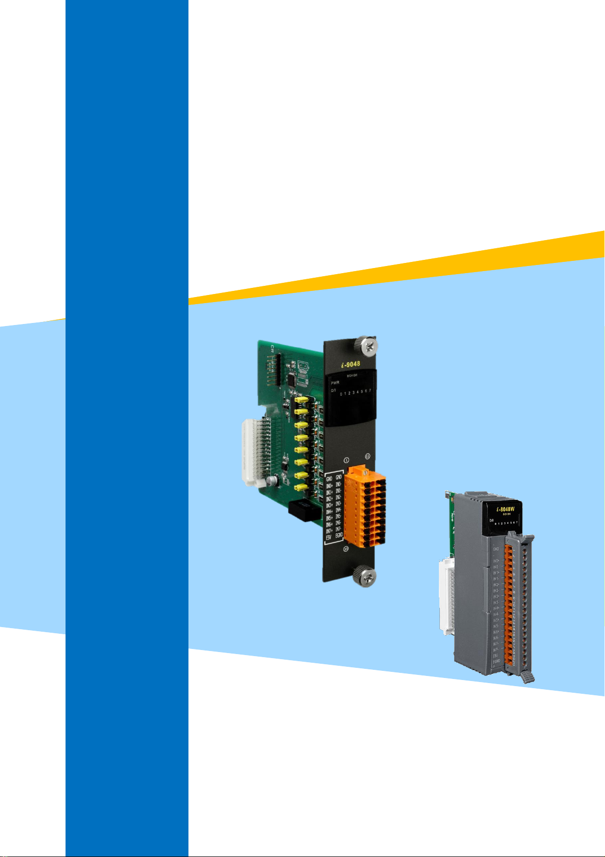
I-9048 / I-8048W Module
Common User Manual
(For Windows/WinCE platform)
V 1.0.2 October 2020
Written by Sean Hsu
Edited by Anna Huang

Warranty
All products manufactured by ICP DAS are under warranty regarding defective materials for a
period of one year, beginning from the date of delivery to the original purchaser.
Warning
ICP DAS assumes no liability for any damage resulting from the use of this product. ICP DAS
reserves the right to change this manual at any time without notice. The information furnished by
ICP DAS is believed to be accurate and reliable. However, no responsibility is assumed by ICP DAS
for its use, nor for any infringements of patents or other rights of third parties resulting from its
use.
Copyright
Copyright © 2020 by ICP DAS Co., Ltd. All rights are reserved.
Trademarks
Names are used for identification purposes only and may be registered trademarks of their
respective companies.
Contact Us
If you have any problems, please feel free to contact us.
You can count on us for a quick response.
Email: service@icpdas.com

Table of Contents
Table of Contents ........................................................................................................................................ 3
Preface ........................................................................................................................................................ 5
1. Introduction ........................................................................................................................................ 6
1.1. I/O Module Dimensions .............................................................................................................. 8
1.2. Inserting the I/O Modules ........................................................................................................... 9
1.3. Wire Connections ...................................................................................................................... 11
1.4. Location of the Demo and library Programs ............................................................................. 12
2. I-9048 / I-8048W module features ................................................................................................... 14
2.1. General Introduction ................................................................................................................. 15
2.1.1. Pin Assignment for the I-9048 ........................................................................................ 17
2.1.2. Pin Assignment for the I-8048W .................................................................................... 18
2.1.3. Block Diagram ................................................................................................................. 19
2.1.4. Isolated or TTL Input ...................................................................................................... 21
2.1.5. Digital Input & LED indicators ......................................................................................... 23
2.1.6. Programmable Rising/Falling interrupt .......................................................................... 24
2.2. Software Introduction ............................................................................................................... 27
2.2.1. Software flow chart ........................................................................................................ 28
2.2.2. Recognize different interrupt service requests .............................................................. 30
3. API References .................................................................................................................................. 33
3.1. Function List .............................................................................................................................. 34
3.2. pac_i8048W_DI_ALL ................................................................................................................. 36
3.3. pac_i8048W_DI_Ch ................................................................................................................... 38
3.4. pac_i8048W_ Set_RisingReg ..................................................................................................... 40
3.5. pac_i8048W_ Set_FallingReg .................................................................................................... 41
3.6. pac_i8048W_Read_RisingReg ................................................................................................... 42
3.7. pac_i8048W_Read_FallingReg .................................................................................................. 43
3.8. pac_i8048W_Read_RisingEvent ................................................................................................ 44
3.9. pac_i8048W_Read_FallingEvent ............................................................................................... 45
3.10. pac_i8048W_Read_RisingEventCount .................................................................................... 46
3.11. pac_i8048W_Read_FallingEventCount ................................................................................... 48
3.12. pac_i8048W_Clear_RisingEventCount .................................................................................... 49
3.13. pac_i8048W_Clear_FallingEventCount ................................................................................... 50
3.14. pac_i8048W_Init ..................................................................................................................... 51

3.15. pac_i8048W_InstallISR ............................................................................................................ 53
3.16. pac_i8048W_UnInstallISR ....................................................................................................... 55
3.17. pac_i8048W_UnFreezeINT ...................................................................................................... 56
3.18. pac_i8048W_GetLibVersion .................................................................................................... 58
3.19. pac_i8048W_GetLibDate ........................................................................................................ 59
Revision History ........................................................................................................................................ 60

Preface
The I-9048 / I-8048W is an 8-channel digital input module with hardware interrupt capability for
real-time system application. Each channel can be programmed as an interrupt input channel to invoke
an interrupt on falling edges, rising edges or both falling and rising edges. Each channel can be eithers
Isolated or Non-isolated TTL Input, selectable by Jumper.
The module includes LED indicators are provided for monitoring DI channel status, together with± 4 kV
ESD protection and 1500 Vrms intra-module isolation.
The information contained in this manual is divided into the following topics:
Chapter 1, “Introduction” – This chapter provides information related to the hardware, such as
the specifications, the jumper settings details and wiring information.
Chapter 2, “I-9048 / I-8048W features” –– This chapter introduces the features of I-9048 /
I-8048W module.
Chapter 3, “API References” – This chapter describes the functions provided in the I-9048 /
I-8048W library together with an explanation of the differences in the naming rules used for the
different Windows platforms.

1. Introduction
Model
I-9K Series
I-8K series
Communication interface
Parallel bus
Parallel bus
Protocol
-
-
Communication speed
Fast
Fast
DI module with latched function
-
-
DI module with counter input
-
-
Power on value for DO module
Y
-
Safe value for DO module
Y
-
Programmable slew-rate for AO module
-
-
Platform
CPU
Slot Counts
WP-9x2x-CE7
AM335x (ARM)
2,4,8
XP-9x7x-WES7
XP-9x8x-WES7
E3827/E3845 (X86)
1,3,7
The I-9K/I-8K series module is based on a parallel interface with high communication speed. The
differences between the I-9K and I-8k series are listed as follows:
I/O module features comparison
Refer to
http://www.icpdas.com/en/product/guide+Remote__I_O__Module__and__Unit+PAC__%EF%BC%86a
mp;__Local__I_O__Modules+I-9K_I-97K__Series for more details regarding of I-9K series module
specification, jumper settings details and wiring information.
Refer to
http://www.icpdas.com/en/product/guide+Remote__I_O__Module__and__Unit+PAC__%EF%BC%86a
mp;__Local__I_O__Modules+I-8K_I-87K__Series__(High__Profile) for more details regarding of I-8K
series module specification, jumper settings details and wiring information.
Those I-9K Modules must work then plugin any slot with the following PAC:

Those I-8K Modules must work then plugin any slot with the following PAC:
Platform
CPU
Slot Counts
WP-8x4x
PXA270 (ARM)
1,4,8
WP-8x2x-CE7
AM335x (ARM)
1,4,8
XP-8x3x-CE6
x86 CPU,1 GHZ, dual-core
1,3,7
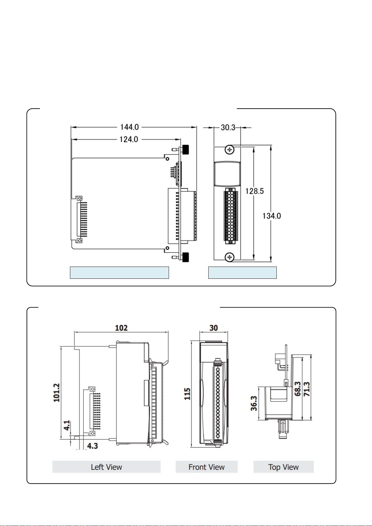
1.1. I/O Module Dimensions
I-9K module with spring clamp terminal connector
Left Side View
Top View
I-8K module with screw terminals connector
All dimensions are in millimeters.
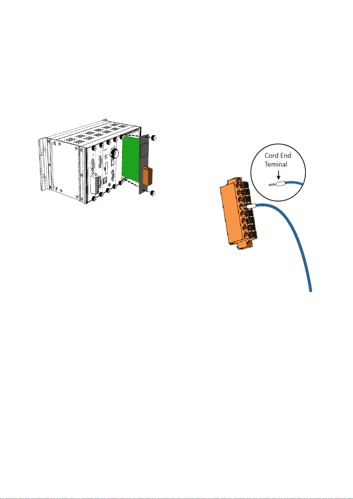
1.2. Inserting the I/O Modules
Follow the procedure described below to insert the I-9048 module.
1. Insert the I/O module
2. Wiring connection
The metal part of the cord end terminal on the wire can be
direct wired to the terminal.
Note:
The I-9048 module supports spring clamp terminal connector. The spring clamp terminal connector for
the I-9048 module connector offers the advantages (anti-vibration, stable clamping and installation
easier) relative to screw terminals.
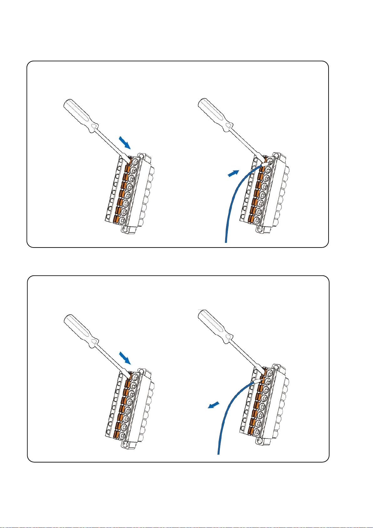
A tip on how to connect the wiring to the connector
1. Use screwdriver to push the orange
clip in.
2. Insert the wiring into the terminal
block
Keep on pushing
Insert the wire
1. Use screwdriver to push the orange
clip in.
2. Remove the wiring from the
terminal block
Keep on pushing
A tip on how to remove the wiring from the connector
1.3. Wire Connections

1.4. Location of the Demo and library Programs
Platform
Location
For WinCE5.0
Library
CD:\napdos\wp-8x4x_ce50\SDK\IO_Modules or
http://ftp.icpdas.com/pub/cd/WinPAC/napdos/wp-8x4x_ce50/SDK/IO_Modules/
Demo
VC:
D:\napdos\wp-8x4x_ce50\Demo\WinPAC\VC2005\IO\IO\Local or
http://ftp.icpdas.com/pub/cd/WinPAC/napdos/wp-8x4x_ce50/Demo/WinPAC/VC2005
/IO/Local/
VB.net:
CD:\napdos\wp-8x4x_ce50\Demo\WinPAC\VB.NET\IO\Local or
http://ftp.icpdas.com/pub/cd/WinPAC/napdos/wp-8x4x_ce50/Demo/WinPAC/VB.NET
/IO/Local/
C#:
CD:\napdos\wp-8x4x_ce50\Demo\WinPAC\C#\IO\Local or
http://ftp.icpdas.com/pub/cd/WinPAC/napdos/wp-8x4x_ce50/Demo/WinPAC/C%23/I
O/Local/
Platform
Location
For WinCE7.0
Library
CD:\VP-x231\SDK\IO_Modules or
http://ftp.icpdas.com/pub/cd/WinPAC_AM335x/VP-x231/SDK/IO_Modules/
Demo
VC:
CD:\VP-x231\demo\PAC\Vc2008\IO\Local or
http://ftp.icpdas.com/pub/cd/WinPAC_AM335x/VP-x231/demo/PAC/Vc2008/IO/
Local/
ICP DAS provides a range of demo programs for different platforms that can be used to verify the
functions of the I-9048 / I-8048W modules. The source code contained in these programs can also be
reused in your own custom programs if needed. The following is a list of the locations where both the
demo programs and associated libraries can be found on either the ICP DAS web site or the enclosed
CD.

VB.net:
CD:\VP-x231\demo\PAC\Vb.net\IO\Local or
http://ftp.icpdas.com/pub/cd/WinPAC_AM335x/VP-x231/demo/PAC/Vb.net/IO/L
ocal/
C#:
CD:\VP-x231\demo\PAC\C#\IO\Local or
http://ftp.icpdas.com/pub/cd/WinPAC_AM335x/VP-x231/demo/PAC/C%23/IO/Lo
cal/
Platform
Location
For WinCE6.0
Library
CD:\SDK\Special_IO or
http://ftp.icpdas.com/pub/cd/XP-8X3X-CE6/SDK/Special_IO/
Demo
VC:
CD:\demo\XPAC\VC2005\IO\Local or
http://ftp.icpdas.com/pub/cd/XP-8X3X-CE6/demo/XPAC/VC2005/IO/Local/
VB.net:
CD:\demo\XPAC\VB.NET\IO\Local or
http://ftp.icpdas.com/pub/cd/XP-8X3X-CE6/demo/XPAC/VB.NET/IO/Local/
C#:
CD:\demo\XPAC\C#\IO\Local or
http://ftp.icpdas.com/pub/cd/XP-8X3X-CE6/demo/XPAC/C%23/IO/local/

2. I-9048 / I-8048W module features
The I-9048 / I-8048W is an 8-channel digital input module with hardware interrupt capability for
real-time system application. Each channel can be programmed as an interrupt input channel to invoke
an interrupt on falling edges, rising edges or both falling and rising edges. Each channel can be eithers
Isolated or Non-isolated TTL Input, selectable by Jumper.
The DI module includes LED indicators are provided for monitoring DI channel status, together with± 4
kV ESD protection and 1500 Vrms intra-module isolation.

2.1. General Introduction
Isolation
Intra-module Isolation
1500 Vrms
EMS Protection
ESD (IEC 61000-4-2)
± 4 kV Contact for Each Terminal
LED Indicators
Status
1 x Power and 8 x DI
Digital Input
Channels
8
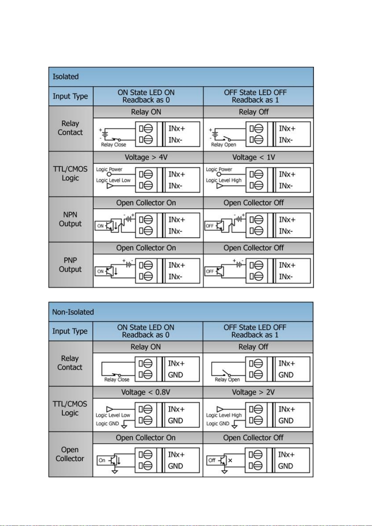
Type
Dry Contact, Wet Contact
Sink/Source (NPN/PNP)
Sink, Source
Wet Contact, ON Voltage Level
Isolated: +4 ~ +30 VDC
Non-Isolated: 0 ~ +0.8 VDC
Wet Contact, OFF Voltage
Level
Isolated: 0 ~ +1 VDC
Non-Isolated: +2 ~ +5 VDC
Input Impedance
2.4 kΩ, 0.5 W
Digital Input/Counter
Interrupts
8 (DI0 ~ DI7) Trigger type: Rising/falling edge
programmable for each channel Max. Interrupt frequency:
10 KHz Max.
Power
Consumption
1.75 W Max.
Environmental
Operating Temperature
-25 ~ +75 °C
Storage Temperature
-40 ~ +85 °C
The I-9048 / I-8048W module is an 8-channel digital input module designed for interrupt
applications.
The key features of the I-9048 / I-8048W are as following:

Environmental
Humidity
10 ~ 90% RH, Non-condensing
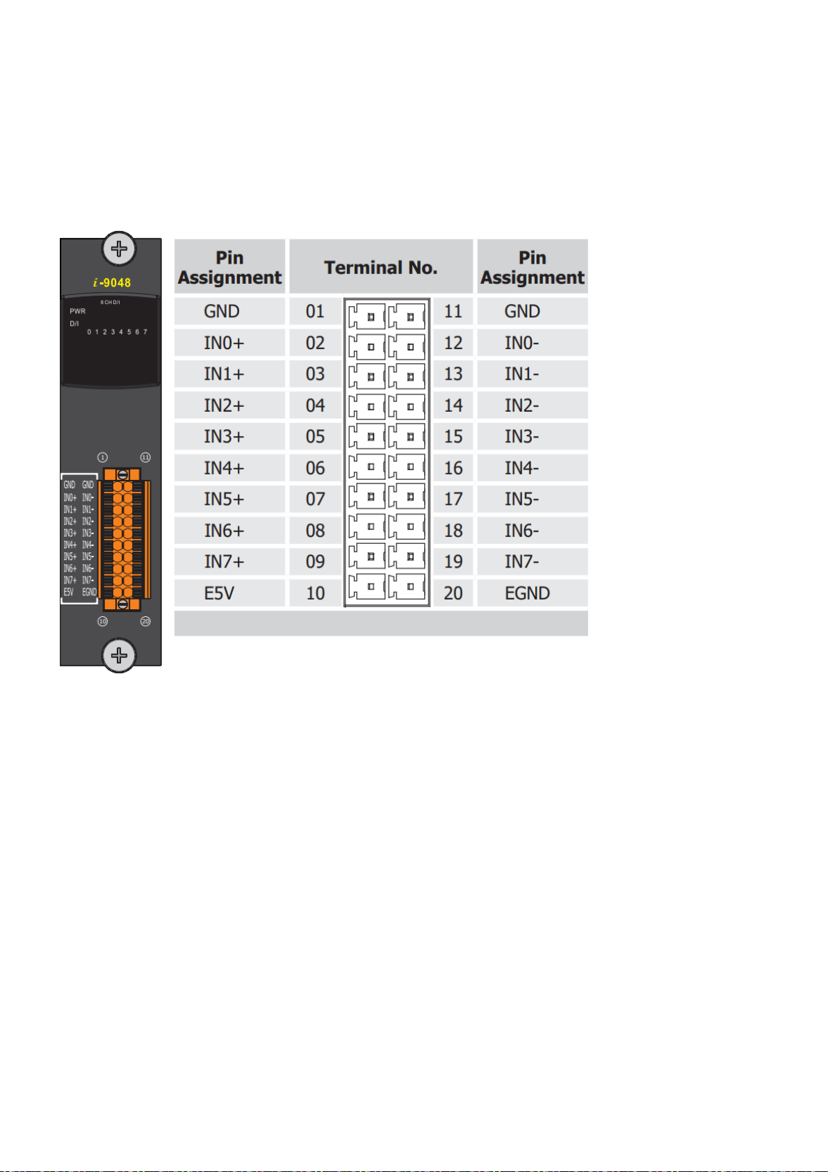
2.1.1. Pin Assignment for the I-9048
The pin assignment for the I-9048 is shown as follows:
Pin 1 and 11: TTL GND, ground for non-isolated input signals
Pins 2 ~ 9、12~19: 8-channel digital input
Pins 10 and 20: Isolated power supply, 5V, 200mA max.
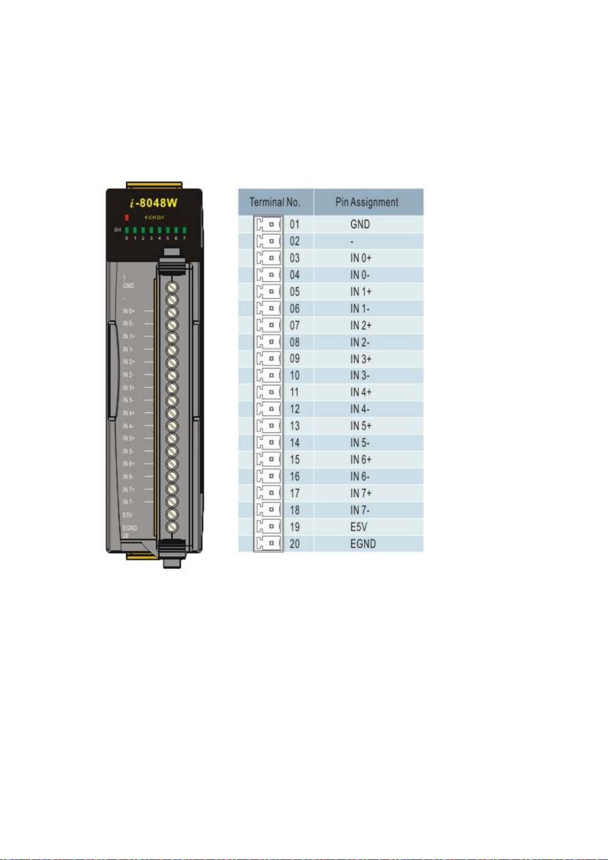
2.1.2. Pin Assignment for the I-8048W
The pin assignment for the I-8048W is shown as follows:
Pin 1: TTL GND, ground for non-isolated input signals
Pins 3 ~ 18: 8-channel digital input
Pins 19 and 20: Isolated power supply, 5V, 200mA max.

2.1.3. Block Diagram
The signal flow block diagram for I-9048 is shown as follows:

The signal flow block diagram for I-8048W is shown as follows:

2.1.4. Isolated or TTL Input
JP1
for ch0
JP2
for ch1
JP3
for ch2
JP4
for ch3
JP5
for ch4
JP6
for ch5
JP7
for ch6
JP8
for ch7
JP1 ~ JP8 in the DOWN position will
select the isolated input 1 ~ 8
V i n -
V i n +
JP1 ~ JP8 in the UP position will
select the TTL input 1 ~ 8
V i n V i n +
The input signal can be either isolated or TTL input for I-9048 as follows:
Isolated input
TTL input
Isolated input (default) TTL input

JP1
for ch0
JP2
for ch1
JP3
for ch2
JP4
for ch3
JP5
for ch4
JP6
for ch5
JP7
for ch6
JP8
for ch7
The input signal can be either isolated or TTL input for I-8048W as follows:
Isolated input
TTL input
Isolated input (default) TTL input

2.1.5. Digital Input & LED indicators
Input status
Digital Input( Logic level )
Electric signal
LED
OPEN 1 Low
OFF
0 ~ +0.8V
0
Low
ON
+2 ~+ 5V
1
High
OFF
Input status
Digital Input( Logic level )
Electric signal
LED
OPEN 1 Low
OFF
0 ~ +1V
1
Low
OFF
+4 ~ +30V
0
High
ON
IN7
IN0
power LED
The LED status and the digital input relation are listed as follows:
Isolated:
TTL:

2.1.6. Programmable Rising/Falling interrupt
Platform
WP-9000-CE7
VC program
10 KHz max.
.NET CF program
0.9 KHz max
Rising Edge Interrupt
Application
Service
Digital Input
(Logic value)
Each channel of the I-9048 can be programmed as one of the following types individually.
Rising edge interrupt input
Falling edge interrupt input
Rising edge and Falling edge interrupt input
Following is the I-9048 interrupt performance
Performance:
The .NET managed callbacks are an order of magnitude slower than VC native callbacks.
The managed callbacks must waste time to check if these are marshaling managed types, packages and
loads any arguments into buffers, makes the call and then packages and marshals any return value. In additional,
the CLR is also doing bookkeeping on the thread states, checking and adjusting GC preemption status, looking
for events and exceptions and potentially sending out debugger and/or profiler information.
The Interrupt trigger types are as follows:

Falling Edge Interrupt
Application
Service
Digital Input
(Logic value)
Rising and falling Edge Interrupt
Application
Service
Digital Input
(Logic value)
T is the leading time between I-9048 receiving the input signal to the application receiving the interrupt
service.
Note: If the interrupt signal is too short, the new status may be as same as old status. In that condition,
the interrupt service thread cannot identify which interrupt source is active. So the interrupt signal
must be hold long enough until the interrupt service thread is executed. This holding time is different
for different hardware & O.S..

Interrupt process for I-9048 / I-8048W on WinCE-Based PAC
OAL
User
Kernel
PAC H/W
IST
ISR
IRQ
I-9048 / I-8048W DI
Interrupt signal
Application thread
Scheduler
Scheduler
T

2.2. Software Introduction
Users can follow the sections to understand the usage of I-9048 / I-8048W Library software.
We offer multi-functions in the I-9048 / I-8048W library, and users can use these functions to develop
I-9048 / I-8048W program.

28
System Kernel
Application
External signal
IST loop
function
Install Interrupt Service Thread
(IST)
Enable falling edge or
rising edge
Initialize
I-9048
ISR
Event
2.2.1. Software flow chart
Initialize I-9048:
Gives all internal variables an initial value. Any interrupt signal clear to low, then all
interrupt will not be blocked and CPU will be able to receive any further interrupts.
The function declaration:
pac_i8048W_Init (int slot)
Enable falling edge or rising edge:
1.
Each channel can set to:
Rising edge interrupt
Falling edge interrupt
Rising edge and Falling edge interrupt
2.
User can enable one channel, several channels or all channels as
I-9048 User Manual, v 1.0.2 E-mail: service@icpdas.com

29
The function declaration:
pac_i8048W_Set_RisingReg (int slot, int channel, int Enable)
pac_i8048W_Set_FallingReg (int slot, int Channel, int Enable)
Install IST
The interrupt service thread (IST) is a thread that does most of the interrupt processing
After installing an IST, when “External signal” enters the I-9048, the kernel
signals the event on behalf of the ISR, and then the IST performs necessary
operations collect the data and process them. When the interrupt processing is
completed, the IST informs the kernel to re-enable the hardware interrupt.
The function declaration:
pac_i8048W_InstallISR(int slot, unsigned long *ISR_Function, int
interrupt signal input.
Priority)
ISR is a piece of code that is built-in or loaded into the kernel, and the user's application
cannot handle this function.A process or driver can create threads (called ISTs)
specifically registered to handle interrupts in user space. After a hardware interrupt occurs,
the ISR processes the interrupt and immediately informs the system to execute the
corresponding IST. ISR and IST are usually used in pairs. Although the API function name
is ISR, it is actually used to install IST
Users can design their own IST functions.
The IST function declaration:
int CALLBACK BackData();
We offer the variable of priority in this function and user can adjust it. When two
slots are interrupted at the same time, the slot of higher priority executes IST first
then slot of lower priority does.
I-9048 User Manual, v 1.0.2 E-mail: service@icpdas.com

30
2.2.2. Recognize different interrupt service requests
I-9048 / I-8048W is an 8 channels rising/falling edge programmable interrupt module. It can plug into
slot of the PAC controllers. The section introduces how to recognize interrupt requests from different
slots and channels.
I-9048 User Manual, v 1.0.2 E-mail: service@icpdas.com

31
Requests from different slots
IST A
IST
B
IST B
IST A
IST
B
IST B
Each slot is assigned an interrupt pin of the CPU shown in section 1.3. So their ISTs are
different. CPU executes different ISR when the request is from different slot.
Considering when the interrupts occur, the situations can be divided to two kinds.
Interrupted at different time
CPU executes ISTs one by one in the order of when they occurred.
Interrupted at the same time
This situation, CPU uses Interrupt Priority to distinguish order of execution. The request with
higher interrupt priority will be serviced first.
In WinCE-based platform
The default priority level of the interrupt service thread for i-8048W/i-9048 is 97. Many
higher priority levels (247 through zero) are assigned to real-time applications, drivers, and
I-9048 User Manual, v 1.0.2 E-mail: service@icpdas.com

32
system processes. .
IST A IST B
IST B
Range Description
0 through 96 Reserved for real-time above drivers.
97 through 152 Used by the default Windows CE-based device drivers.
153 through 247 Reserved for real-time below drivers.
It's recommended to set the priority level between 97 and 152 for i-8048w/i-9048 IST
For example:
A’s priority is 97
B’s priority is 100
CPU gets two requests, A and B, at the same time. Because A’s priority is higher than B,
CPU services A’s request to execute IST_A first. And IST_B will not be executed unless
ISR_T is finished.
When you assign an interrupt priority for the 9048, you need to consider all interrupt
services of the system.
I-9048 User Manual, v 1.0.2 E-mail: service@icpdas.com

33
3. API References
ICPDAS supplies a range of C/C++ API functions for the I-9048 module. When developing a custom
program, refer to pac_i8048W.h/ pac_i8048W.lib/ pac_i8048W.dll, or the API functions described in the
following sections for more detailed information.
ICPDAS also supplies a range of .NET framework function that can be used to develop custom .NET
framework programs. These functions are ported from the relevant C/C++ functions. For more
information related to the .NET framework functions, refer to the pac_i8048WNet.dll file.
The number and name for each pac_i8048W.dll and pac_i8048WNet.dll function for WP-8000 and
WP-9000 series are the same. The benefits of the implementing a unified SDK is that the programs for
each platform can be easily migrated.
More details of where to find the relevant libraries and files, and refer to Chapter 1.3. Location of the
Demo and Library Programs.
I-9048 User Manual, v 1.0.2 E-mail: service@icpdas.com

34
3.1. Function List
Systematics
Function
Description
DI Read
pac_i8048W_DI_ALL
This function reads the full channel DI
value of the I-9048 module.
pac_i8048W_DI _Ch
This function read the single-channel
DI status of the I-9048 module.
RisingReg /
FallingReg
pac_i8048W_ Set_RisingReg
This function Enable/Disable the rising
interrupt of an I-9048 channel.
pac_i8048W_ Set_FallingReg
This function Enable/Disable the falling
interrupt of an I-9048W channel.
pac_i8048W_ Read_RisingReg
This function Read the rising interrupt
setting status of an I-9048 channel.
pac_i8048W_ Read_ FallingReg
This function Read the falling interrupt
setting status of an I-9048 channel.
Event
pac_i8048W_ Read_RisingEvent
This function read rising interrupt status
from the I-9048 modules.
pac_i8048W_ Read_FallingEvent
This function read falling interrupt
status from the I-9048 modules.
pac_i8048W_ Read_RisingEventCount
This function read total count values of
the rising interrupt occurred on an
i-9048 channel.
pac_i8048W_ Read_FallingEventCount
This function read total count values of
the rising interrupt occurred on an
I-9048 channel.
The common API functions of 9048 Module list as below table. Detailed information related to individual
functions can be found in the following sections.
I-9048 User Manual, v 1.0.2 E-mail: service@icpdas.com

35
pac_i8048W_ Clear_RisingEventCount
This function clear total count values of
the rising interrupt occurred on an
I-9048 channel
pac_i8048W_ Clear_FallingEventCount
This function clear total count values of
the falling interrupt occurred on an
I-9048 channel
Init
pac_i8048W_ Init
This function sets the rising or falling
trigger type of the I-9048 module.
Interrupt service
routine
pac_i8048W_ InstallISR
This function is used to install a slot
interrupt service route for I-9048 with
the thread priority.
pac_i8048W_UnInstallISR
This function is used to uninstall a slot
interrupt service route and disable a
hardware interrupt.
pac_i8048W_ UnFreezeINT
This function clears interrupt status of
the I-9048 channel.
Library
pac_i8048W_ GetLibVersion
This function to get the library version of
I-9048.
pac_i8048W_ GetLibDate
This function to get the library built date.
I-9048 User Manual, v 1.0.2 E-mail: service@icpdas.com

36
3.2. pac_i8048W_DI_ALL
This function reads the full channel DI value of the I-9048 module.
Syntax
C++
int pac_i8048W_DI_ALL (
int iSlot
);
Parameters
iSlot
[in] Specifies the slot number (0 - 7).
Return Value
Return the full channel DI value.
I-9048 User Manual, v 1.0.2 E-mail: service@icpdas.com

37
Example
[C]
BYTE byteData=0;
int slotNumber = 0;
byteData = pac_i8048W_DI_ALL(slotNumber) ;
[C#]
int slotNumber = 0;
int DI = pac8048W.DI_ALL(slotNumber);
Remarks
None.
I-9048 User Manual, v 1.0.2 E-mail: service@icpdas.com

38
3.3. pac_i8048W_DI_Ch
This function read the single-channel DI status of the I-9048 module.
Syntax
C++
int pac_i8048W_DI_Ch(
int slot,
int DI_Channel,
);
Parameters
slot
[in] Specifies the slot number (0 - 7).
DI_Channel
[in] The single channel of the I-9048 module to be read.
Return Value
1 DI ON
0 DI OFF
I-9048 User Manual, v 1.0.2 E-mail: service@icpdas.com

39
Example
[C]
int DI=0;
int channel = 0;
int slot = 0;
DI = pac_i8048W_DI_Ch(slot, channel);
[C#]
int DI=0;
int channel = 0;
int slot = 0;
DI = pac8048W.DI_Ch(slot, channel);
I-9048 User Manual, v 1.0.2 E-mail: service@icpdas.com

40
3.4. pac_i8048W_ Set_RisingReg
This function is used to Enable/Disable the Rising interrupt of an I-9048 channel.
Syntax
C++
void pac_i8048W_Set_RisingReg(
int slot,
int channel,
int enable
);
Parameters
slot
[in] Specifies the slot number (0 - 7).
channel
[in] Specifies the channel number ( 0 to 7).
Enable
[in] Select Enable or Disable, 1=Enable, 0=Disable
Return Value
None
I-9048 User Manual, v 1.0.2 E-mail: service@icpdas.com

41
3.5. pac_i8048W_ Set_FallingReg
This function is used to Enable/Disable the Falling interrupt of an I-9048 channel.
Syntax
C++
void pac_i8048W_Set_FallingReg(
int slot,
int channel,
int enable
);
Parameters
slot
[in] Specifies the slot number (0 - 7).
channel
[in] Specifies the channel number ( 0 to 7).
Enable
[in] Select Enable or Disable, 1=Enable, 0=Disable
Return Value
None
I-9048 User Manual, v 1.0.2 E-mail: service@icpdas.com

42
3.6. pac_i8048W_Read_RisingReg
This function Read the rising interrupt setting status of an I-9048 channel.
Syntax
C++
int pac_i8048W_Read_RisingReg (
int slot,
int channel
);
Parameters
slot
[in] Specifies the slot number (0 - 7).
channel
[in] Specifies the channel number ( 0 to 7).
Return Value
I-9048 User Manual, v 1.0.2 E-mail: service@icpdas.com

43
3.7. pac_i8048W_Read_FallingReg
This function Read the falling interrupt setting status of an I-9048 channel.
Syntax
C++
int pac_i8048W_Read_FallingReg (
int slot,
int channel
);
Parameters
slot
[in] specifies the slot number (0 - 7).
channel
[in] Specifies the channel number ( 0 to 7).
Return Value
I-9048 User Manual, v 1.0.2 E-mail: service@icpdas.com

44
3.8. pac_i8048W_Read_RisingEvent
This function read rising interrupt status from the I-9048 modules.
Syntax
C++
int pac_i8048W_Read_RisingEvent(
int slot,
int channel
);
Parameters
slot
[in] specifies the slot number (0 - 7).
channel
[in] Specifies the channel number( 0 to 7).
Return Value
I-9048 User Manual, v 1.0.2 E-mail: service@icpdas.com

45
3.9. pac_i8048W_Read_FallingEvent
This function read falling interrupt status from the I-9048 modules.
Syntax
C++
int pac__i8048W_Read_FallingEvent (
int slot,
int channel
);
Parameters
slot
[in] Specifies the slot number (0 - 7).
channel
[in] Specifies the channel number ( 0 to 7).
Return Value
I-9048 User Manual, v 1.0.2 E-mail: service@icpdas.com

46
3.10. pac_i8048W_Read_RisingEventCount
This function read total count values of the rising interrupt occurred on an i-9048 channel.
Syntax
C++
DWORD pac_i8048W_Read_RisingEventCount(
int slot,
int channel
);
Parameters
slot
[in] Specifies the slot number (0 - 7).
channel
[in] Specifies the channel number ( 0 to 7).
Return Value
I-9048 User Manual, v 1.0.2 E-mail: service@icpdas.com

47
I-9048 User Manual, v 1.0.2 E-mail: service@icpdas.com

48
3.11. pac_i8048W_Read_FallingEventCount
This function read total count values of the rising interrupt occurred on an I-9048 channel.
Syntax
C++
DWORD pac_i8048W_Read_FallingEventCount(
int slot,
int channel
);
Parameters
slot
[in] Specifies the slot number (0 - 7).
channel
[in] Specifies the channel number ( 0 to 7).
Return Value
I-9048 User Manual, v 1.0.2 E-mail: service@icpdas.com

49
3.12. pac_i8048W_Clear_RisingEventCount
This function clear total count values of the rising interrupt occurred on an I-9048 channel.
Syntax
C++
void pac_i8048W_Clear_RisingEventCount (
int slot,
int channel
);
Parameters
slot
[in] Specifies the slot number (0 - 7).
channel
[in] Specifies the channel number ( 0 to 7).
Return Values None
Return Value
None.
I-9048 User Manual, v 1.0.2 E-mail: service@icpdas.com

50
3.13. pac_i8048W_Clear_FallingEventCount
This function clear total count values of the falling interrupt occurred on an I-9048 channel.
Syntax
C++
void pac_i8048W_Clear_FallingEventCount (
int slot,
int channel
);
Parameters
slot
[in] Specifies the slot number (0 - 7).
channel
[in] Specifies the channel number ( 0 to 7).
Return Value
None
I-9048 User Manual, v 1.0.2 E-mail: service@icpdas.com

51
3.14. pac_i8048W_Init
This function is used to initialize the driver and confirm the hardware ID of the I-9048 module.
Syntax
C++
int pac_i8048W_Init(
int iSlot
);
Parameters
iSlot
[in] Specifies the slot number (0 - 7).
Return Value
Return 0 if success, otherwise false.
I-9048 User Manual, v 1.0.2 E-mail: service@icpdas.com

52
Example
[C]
int ret = 0;
int slotNumber =0;
ret = pac_i8048W_Init(slotNumber);
[C#]
int slotNumber =0;
bool iRet=pac8048W.Init(slotNumber);
I-9048 User Manual, v 1.0.2 E-mail: service@icpdas.com

53
3.15. pac_i8048W_InstallISR
This function is used to install a slot interrupt service thread for I-9048 with the thread priority.
Syntax
C++
void pac_i8048W_InstallISR (
int iSlot,
PAC_CALLBACK_FUNC IST_Function,
int priority
);
Parameters
iSlot
[in] Specifies the slot number (0 - 7).
ISR_Function
[in] After installing an IST, the CPU will execute the ISR_Function when “External signal” enters the
9048.
priority
[in] When two slots are interrupted at the same time, the slot of higher priority executes IST first
then slot of lower priority does.
Return Value
None
I-9048 User Manual, v 1.0.2 E-mail: service@icpdas.com

54
Example
[C]
int slotNumber = 1;
int channelNumber =1;
int ret=0;
int ipriority=100;
ret = pac_i8048W_Init(slotNumber);
if (!ret){
pac_i8048W_Set_RisingReg(slotNumber,channelNumber,1);
pac_i8048W_Set_FallingReg(slotNumber,channelNumber,0);
pac_i8048W_InstallISR(slotNumber,BackData,ipriority);
}
…
int CALLBACK BackData(){
int temp = 0;
….
pac_i8048W_UnFreezeINT(slotNumber,channelNumber);
return 1;
}
Remarks
[WinCE based]
The default priority level of the interrupt service thread,Interrupt_Fun function for i-8048W/i-9048
is 97
Many higher priority levels (247 through zero) are assigned to real-time applications, drivers, and
system processes. .
Range Description
0 through 96 Reserved for real-time above drivers.
97 through 152 Used by the default Windows CE-based device drivers.
153 through 247 Reserved for real-time below drivers.
It's recommended to set the priority level between 97 and 152 for i-8048w/i-9048 IST.
I-9048 User Manual, v 1.0.2 E-mail: service@icpdas.com

55
3.16. pac_i8048W_UnInstallISR
This function is used to uninstall a slot interrupt service thread and disable a hardware interrupt.
Syntax
C++
void pac_i8048W_UnInstallISR (
int iSlot,
);
Parameters
iSlot
[in] Specifies the slot number (0 - 7).
Return Value
None
Example
[C]
int slotNumber = 1;
pac_i8048W_UnInstallISR(slotNumber);
I-9048 User Manual, v 1.0.2 E-mail: service@icpdas.com

56
3.17. pac_i8048W_UnFreezeINT
This function clear interrupt status of the I-9048 channel.
Syntax
C++
void pac_i8048W_UnFreezeINT(
int slot,
int channel
);
Parameters
slot
[in] Specifies the slot number (0 - 7).
channel
[in] Specifies the channel number ( 0 to 7).
Return Value
None
I-9048 User Manual, v 1.0.2 E-mail: service@icpdas.com

57
Examples
[C]
int channel = 0;
int slotNumber =0;
pac_i8048W_UnFreezeINT(slotNumber,channel);
[C#]
int channel = 0;
int slotNumber =0;
pac8048W.UnFreezeINT(slotNumber,channel);
I-9048 User Manual, v 1.0.2 E-mail: service@icpdas.com

58
3.18. pac_i8048W_GetLibVersion
This function to get the library version of I-9048W.
Syntax
C++
short pac_i8048W_GetLibVersion()
Return Value
Version number
For Example : 0x106 = Rev 1.0.6
I-9048 User Manual, v 1.0.2 E-mail: service@icpdas.com

59
3.19. pac_i8048W_GetLibDate
This function to get the library built date.
Syntax
C++
void pac_i8048W_GetLibDate(
char LibDate[]
);
Parameters
LibDate
[out] library built date.
Return Value
None
I-9048 User Manual, v 1.0.2 E-mail: service@icpdas.com

60
Revision History
Revision
Date
Description
1.0.2
October 2020
Initial issue
This chapter provides revision history information to this document.
The table below shows the revision history.
I-9048 User Manual, v 1.0.2 E-mail: service@icpdas.com
 Loading...