

ICPDAS I-7567 User Manual

I-7567 USB/HART Converter User’s Manual (Ver 1.3, 2015/10/30) ------------- 1
User’s Manual
Warranty
All products manufactured by ICP DAS are under warranty regarding
defective materials for a period of one year from the date of delivery to the
original purchaser.
Warning
ICP DAS assumes no liability for damages resulting from the use of
this product. ICP DAS reserves the right to change this manual at any time
without notice. The information furnished by ICP DAS is believed to be
accurate and reliable. However, no responsibility is assumed by ICP DAS
for its use, or for any infringements of patents or other rights of third
parties resulting from its use.
Copyright
Copyright 2011 by ICP DAS. All rights are reserved.
Trademark
The names used for identification only may be registered trademarks
of their respective companies.
I-7567
USB To HART Converter

I-7567 USB/HART Converter User’s Manual (Ver 1.3, 2015/10/30) ------------- 2
Table of Contents
1. Introduction ....................................................................................... 4
1.1 Features ............................................................................................. 4
1.2 Specifications ..................................................................................... 5
2. Hardware ........................................................................................... 7
2.1 Block Diagram .................................................................................... 8
2.2 Pin Assignment of HART Port ............................................................ 9
2.2.1 Pin Function Description .................................................................. 9
2.2.2 HART Connection ............................................................................ 9
2.3 Terminator Resistor Settings ............................................................ 12
2.4 Init / Normal Jumper ......................................................................... 13
2.4.1 Firmware Update Mode .................................................................. 13
2.4.2 Firmware Operation Mode .............................................................. 14
2.5 LED Indication .................................................................................. 15
2.5.1 LED function ................................ ................................ ................... 15
2.5.2 LED indication Table ....................................................................... 16
2.6 Cable Selection ................................................................................ 16
3. Driver Installation ............................................................................ 17
3.1 Install I-7567 Driver Automatically .................................................... 17
3.2 Install I-7567 Driver by Manual ........................................................ 18
3.3 Verify Driver Installation ................................................................... 21
3.4 Uninstall I-7567 Driver ...................................................................... 22
3.5 Install I-7567 Driver in Win10 ................................ ........................... 23
4. HC_Tool Utility ................................................................................ 28
4.1 Run Utility ......................................................................................... 28
4.2 Serial Port and HART Command Settings ....................................... 28
4.2.1 Serial port settings ......................................................................... 28
4.2.2 HART Frame Settings .................................................................... 29
4.3 Search HART devices ...................................................................... 30
4.3.1 Search HART devices automatically .............................................. 30
4.3.2 Search HART devices by manual ................................................... 31
4.3.3 Search HART devices .................................................................... 32
4.4 Send / Receive HART Frame (SRMsg) ............................................ 34
4.5 HART Information Log (Data Log) .................................................... 36
4.6 HART Configuration (HTCfg) ........................................................... 37
4.7 Module Configuration (ModCfg) ....................................................... 39
5. FAQ .................................................................................................. 42

I-7567 USB/HART Converter User’s Manual (Ver 1.3, 2015/10/30) ------------- 3
Q01 : How to use I-7567 to communicate with HART devices ? .......................... 42
Q02 : Does I-7567 support the API Library for HART ? ....................................... 42
Q03 : Can I-7567 work in Win10 ? ....................................................................... 42
6. History Version ................................................................................ 43
I-7567 USB/HART Converter User’s Manual (Ver 1.3, 2015/10/30) ------------- 4
1. Introduction
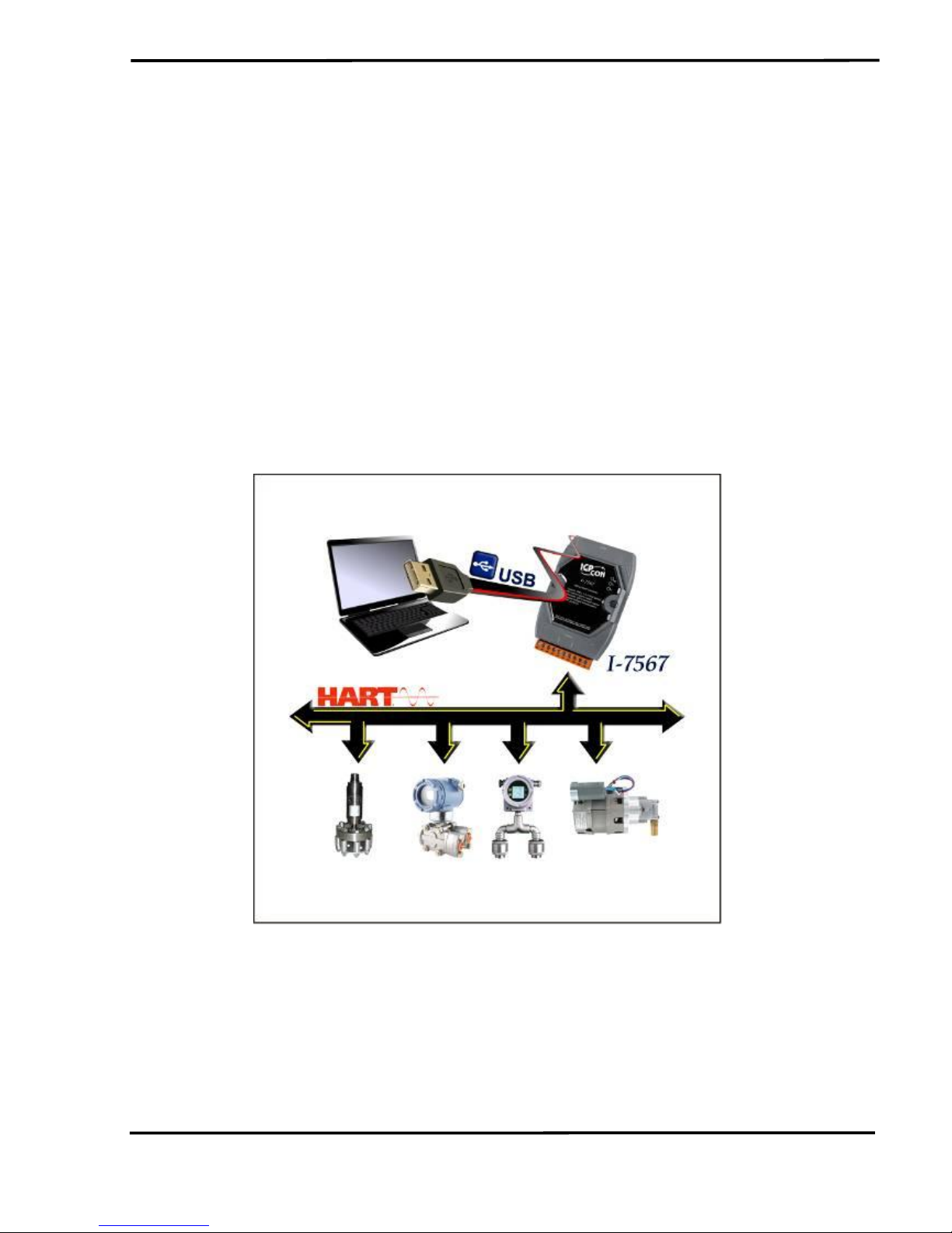
The I-7567 is a USB to HART converter specially designed as the
master device of HART protocol. It allows users to access the HART slave
via virtual COM-port of PC and the baud rate must be set 1200 bps.
When connecting I-7567 to PC, PC will load the relevant device driver
automatically (hot plug & play). Therefore, users can make data collection
and processing of HART network easier and quicker by applying I-7567. In
addition, by using the I-7567 utility, users can configure module and test
HART communication easily.
The following is the application structure of the USB/HART modules.
1.1 Features
Support HART Short/Long frame
Support HART Burst mode.

I-7567 USB/HART Converter User’s Manual (Ver 1.3, 2015/10/30) ------------- 5
Support point-to-point or multi-drop HART mode.
Support connecting up to 15 HART slave devices.
Allow two HART masters.
Provide utility tool for module configuration and HART communication.
No external power supply (powered by USB)
Support firmware update via USB
Provide PWR / Tx / Rx indication LED
4KV ESD Protection
Selectable 250Ω load resistor (1/4W)
1.2 Specifications
[ USB Spec. ]
Input port : USB (USB Type B)
Compatibility : USB 1.1 and 2.0 standard
Driver Supported : Windows 2000 / XP / Vista / 7 (32/64 bit)
Virtual COM Parameter : 1200 bps, O(odd parity), 8(data bit), 1(stop bit)
[ HART Spec. ]
Channel : 1
Connector : 2-pin screwed terminal-block
Network : Point to Point or Multi-drop
Baud Rate : 1200 bps
Frame : Short or Long
Operates as a HART Master and supports all HART commands
Support up to 15 HART slave devices
Isolation Voltage : 3KVdc on the HART side
[ Module Spec. ]
Dimensions : 108mm x 72mm x 35mm (H x W x D)
Operating temperature : -25 to 75ºC (-13 to 167ºF);
Storage temperature : -30 to 75ºC (-22 to 167ºF);
Humidity : 5 to 95%, non-condensing;
Indication LEDs :
PWR LED : Module power status

I-7567 USB/HART Converter User’s Manual (Ver 1.3, 2015/10/30) ------------- 6
Tx LED : Data received from USB
Rx LED : Data received from HART port
[ Utility Tool ]
Provide module configuration and HART communication easily and
quickly.
Provide HART devices search automatically.
Provide diagnostic Information of HART device.
Provide data logging for HART communication.
[ Application ]
Current Measuring;
Petrochemical Industry Application;
Environment Monitoring;
Tunnel Monitoring;
Monitor system;
Building Monitoring etc.;
I-7567 USB/HART Converter User’s Manual (Ver 1.3, 2015/10/30) ------------- 7
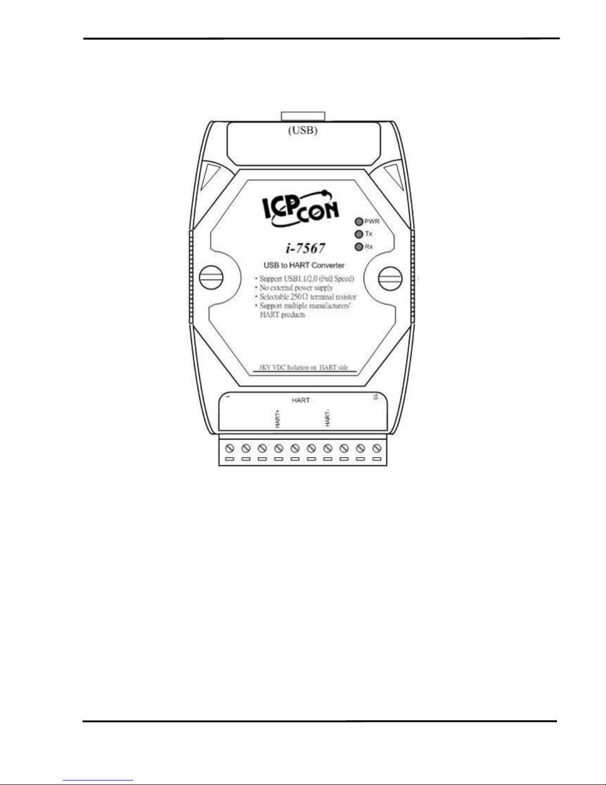
2. Hardware
Figure 2-1: Hardware externals of I-7567
I-7567 USB/HART Converter User’s Manual (Ver 1.3, 2015/10/30) ------------- 8
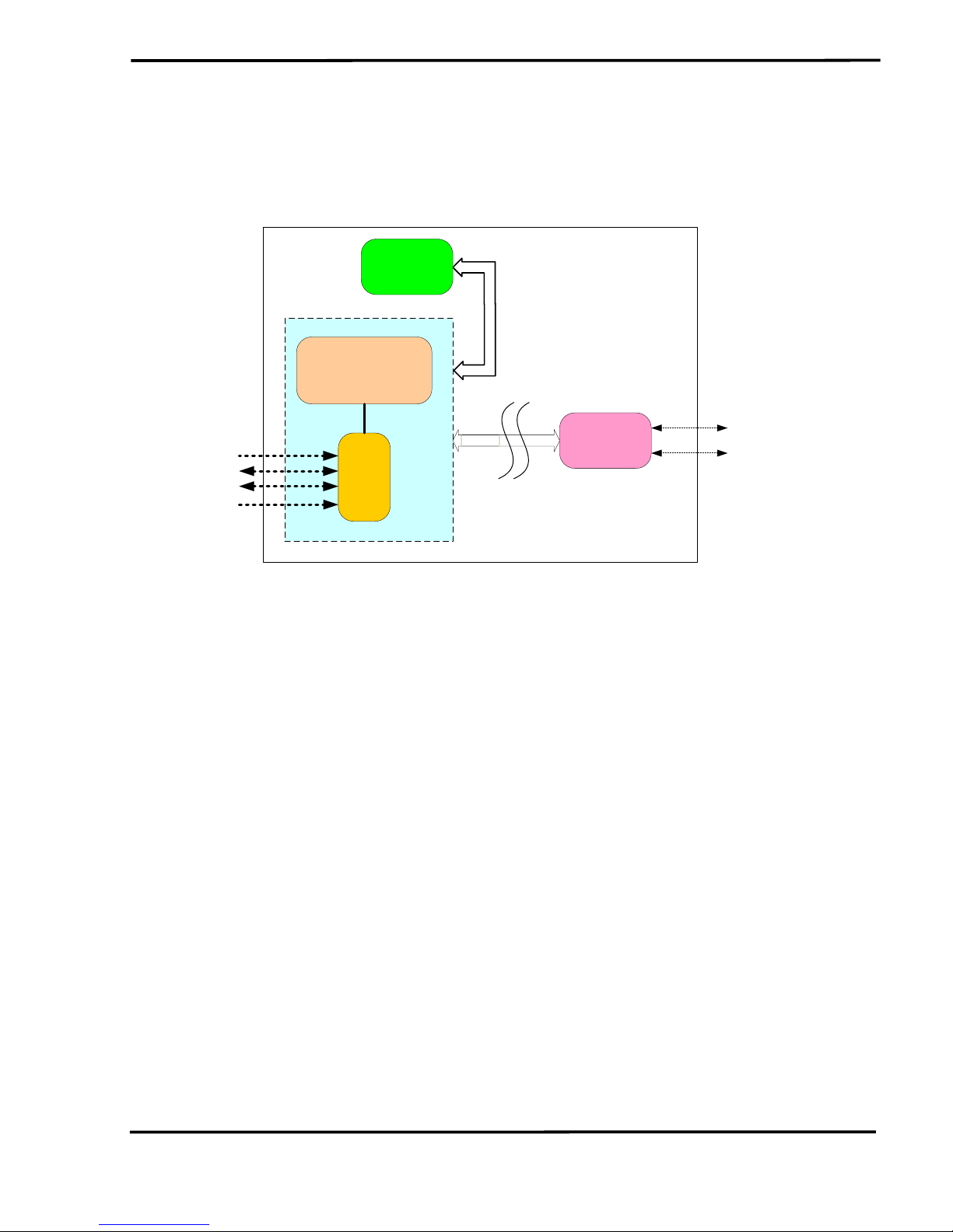
2.1 Block Diagram
Figure 2-2 is a block diagram illustrating the functions on the I-7567
module. It provides the 3000Vrms Isolation in the HART interface site.
VBUS
DATA0+
DATA0-
GND
MICROPROCESSOR
MCU
USB
Driver
LED
module
HART
modem
3000V
Isolation
HART+
HART-
Figure 2-2: Block diagram of I-7567

I-7567 USB/HART Converter User’s Manual (Ver 1.3, 2015/10/30) ------------- 9
2.2 Pin Assignment of HART Port
Figure 2-3: Pin Assignment on I-7567
2.2.1 Pin Function Description
Pin No.
Pin Name
Pin Function Description
1
-
N/A 2 -
N/A 3 -
N/A 4 HART+
HART+ 5 -
N/A 6 -
N/A 7 HART-
HART- 8 -
N/A 9 -
N/A
10
-
N/A
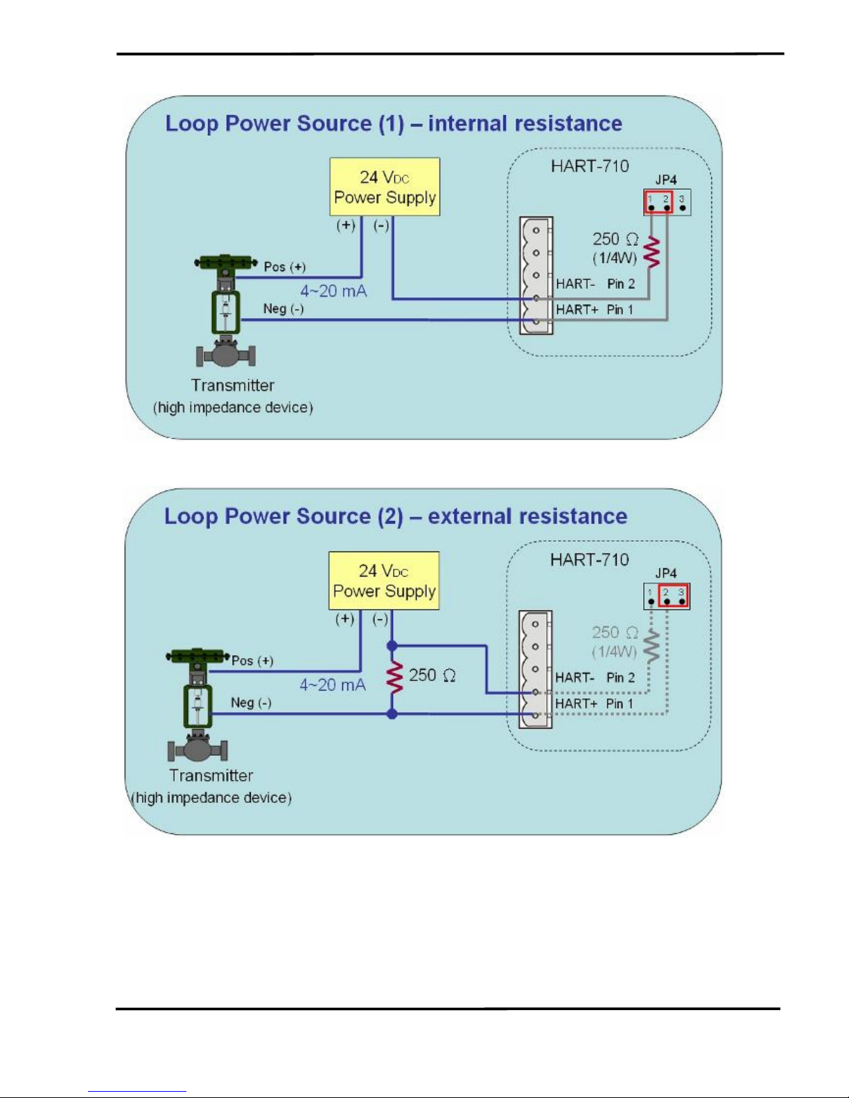
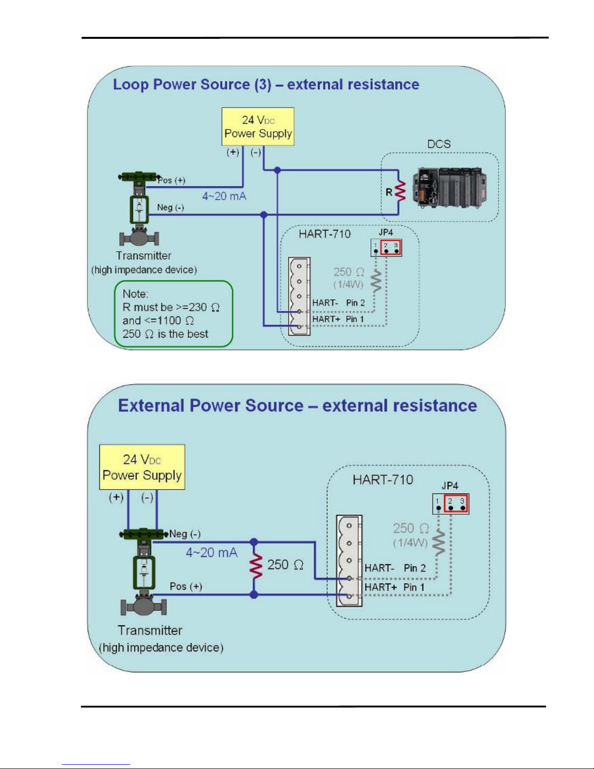
2.2.2 HART Connection
The HART connection can be divided to the following two types :
(1) ”Loop Power Source” Mode.
(2) ”External Power Source” Mode.
I-7567 USB/HART Converter User’s Manual (Ver 1.3, 2015/10/30) ------------- 10
Ex1 : Loop Power Source (Internal Resistance)
Ex2 : Loop Power Source (External Resistance)
I-7567 USB/HART Converter User’s Manual (Ver 1.3, 2015/10/30) ------------- 11
Ex3 : Loop Power Source (External Resistance)
Ex4 : External Power Source (Internal Resistance)
I-7567 USB/HART Converter User’s Manual (Ver 1.3, 2015/10/30) ------------- 12
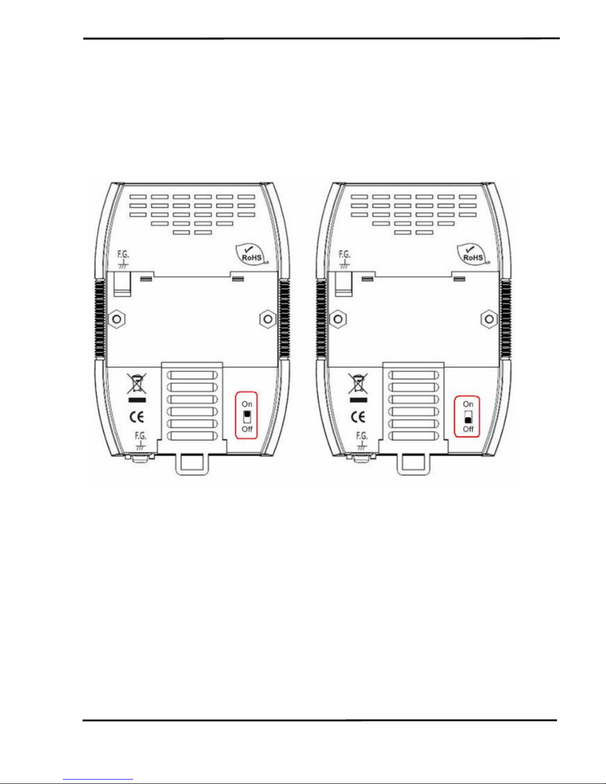
2.3 Terminator Resistor Settings
The DIP switch is used to provide HART network with 250 Ω (1/4 W)
resistor. When it is set to “On”, the resistor will connect to HART network.
Otherwise, it will disconnect the resistor from HART network. The default
position of the DIP switch is in “On”.
Figure 2-5: Enable Internal Resistor. Figure 2-6: Disable Internal Resistor.
I-7567 USB/HART Converter User’s Manual (Ver 1.3, 2015/10/30) ------------- 13
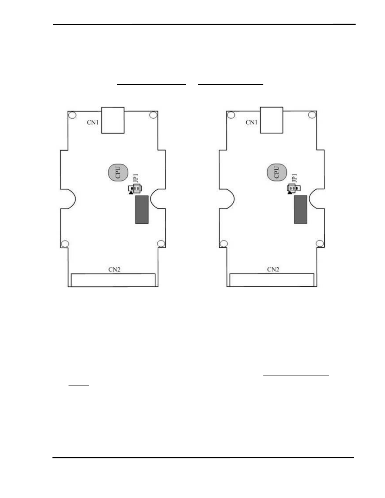
2.4 Init / Normal Jumper
Open the shell of I-7567 and there is a jumper (JP1) on the PCB of I7567 is used for firmware operation or firmware updating function of I7567 module.
Figure 2-7: Firmware Operation Figure 2-8: Firmware Updating
2.4.1 Firmware Update Mode
Please follow the below steps to complete the firmware update
process of I-7567.
(1) Set the jumper (JP1) to the firmware updating position like Figure 2-8
and reboot I-7567. Then I-7567 will work in the “Firmware Update
Mode”. In this mode, users can update the firmware of I-7567 module
via USB and the I-7567 will become a “USB Mass Storage” device like
Figure 2-9.
 Loading...