

ICPDAS I-7565-H1, I-7565-H2 User Manual

I-7565-H1 / I-7565-H2
Hi
g
h Performance USB/CA
N
Converter
User’s Manual
Warranty
All products manufactured by ICP DAS are under warranty regarding
defective materials for a period of one year from the date of delivery to the
original purchaser.
Warning
ICP DAS assumes no liability for damages resulting from the use of
this product. ICP DAS reserves the right to change this manual at any time
without notice. The information furnished by ICP DAS is believed to be
accurate and reliable. However, no responsibility is assumed by ICP DAS
for its use, or for any infringements of patents or other rights of third
parties resulting from its use.
Copyright
Copyright 2009 by ICP DAS. All rights are reserved.
Trademark
The names used for identification only may be registered trademarks
of their respective companies.
I-7565-H1/H2 High Performance USB/CAN Converter User’s Manual (Ver 1.7, Aug/2011) ------------- 1

Table of Contents
1. Introduction ........................................................................................5
1.1 Features............................................................................................. 6
1.2 Specifications..................................................................................... 6
2. Hardware.............................................................................................8
2.1 Block Diagram.................................................................................... 8
2.2 Pin Assignment of CAN Port .............................................................. 9
2.3 Hardware Connection ........................................................................ 9
2.4 Terminator Resistor Settings .............................................................11
2.5 Init / Normal Dip-switch .................................................................... 12
2.5.1 Firmware Update Mode.................................................................. 12
2.5.2 Firmware Operation Mode.............................................................. 13
2.6 LED Indication.................................................................................. 15
2.7 Cable Selection................................................................................ 16
3. Driver Installation.............................................................................18
3.1 Install I-7565-H1/H2 Driver by Auto.................................................. 18
3.2 Install I-7565-H1/H2 Driver by Manual ............................................. 19
3.3 Verify Driver Installation ................................................................... 22
3.4 Uninstall I-7565-H1/H2 Driver .......................................................... 23
4. Software Utility.................................................................................24
4.1 INI File Function............................................................................... 24
4.2 Connection Function ........................................................................ 24
4.3 Communication Function ................................................................. 27
4.4 Config Function................................................................................ 32
4.4.1 Module Config Function ................................................................. 32
4.4.2 Advanced Config Function ............................................................. 36
4.4.3 Extra Config Function..................................................................... 38
4.5 Data Log Function............................................................................ 39
4.6 Status Bar Function.......................................................................... 42
5. API Library -- VCI_CAN.dll...............................................................43
5.1 API Library Overview ....................................................................... 43
5.2 API Library Function Table............................................................... 44
5.3 Flow Chart for Users’ Program Development by Using API ............. 46
5.4 Init Function ..................................................................................... 47
5.4.1 VCI_OpenCAN............................................................................... 47
5.4.2 VCI_CloseCAN .............................................................................. 49
5.5 Module Config Function ................................................................... 50
I-7565-H1/H2 High Performance USB/CAN Converter User’s Manual (Ver 1.7, Aug/2011) ------------- 2

5.5.1 VCI_Set_CANFID .......................................................................... 50
5.5.2 VCI_Get_CANFID .......................................................................... 52
5.5.3 VCI_Get_CANStatus ...................................................................... 54
5.5.4 VCI_Clr_BufOverflowLED .............................................................. 55
5.5.5 VCI_Get_MODInfo ......................................................................... 56
5.5.6 VCI_Rst_MOD ............................................................................... 57
5.6 Communication Function ................................................................. 58
5.6.1 VCI_SendCANMsg ........................................................................ 58
5.6.2 VCI_RecvCANMsg......................................................................... 60
5.6.3 VCI_EnableHWCyclicTxMsg.......................................................... 62
5.6.4 VCI_DisableHWCyclicTxMsg ......................................................... 64
5.6.5 VCI_EnableHWCyclicTxMsgNo ..................................................... 65
5.6.6 VCI_EnableHWCyclicTxMsgNo_Ex ............................................... 67
5.6.7 VCI_DisableHWCyclicTxMsgNo .................................................... 69
5.7 Software Buffer Function.................................................................. 70
5.7.1 VCI_Get_RxMsgCnt....................................................................... 70
5.7.2 VCI_Get_RxMsgBufIsFull .............................................................. 71
5.7.3 VCI_Clr_RxMsgBuf ........................................................................ 72
5.8 User Defined ISR Function .............................................................. 73
5.8.1 VCI_Set_UserDefISR..................................................................... 73
5.8.2 VCI_Clr_UserDefISR ..................................................................... 75
5.8.3 VCI_Get_ISRCANData .................................................................. 76
5.9 Other Function ................................................................................. 77
5.9.1 VCI_Get_DllVer.............................................................................. 77
5.9.2 VCI_DoEvents................................................................................ 78
5.10 Return Code..................................................................................... 79
6. API Library -- mVCI_CAN.dll............................................................80
6.1 For VC Project ................................................................................. 80
6.2 For VB Project.................................................................................. 81
6.3 For .Net Project................................................................................ 83
7. Troubleshooting...............................................................................84
7.1 The Connection Issue ...................................................................... 84
7.2 The CAN Baud Rate Issue............................................................... 85
7.3 The Same CAN-ID Conflict Issue..................................................... 87
7.4 The PC Rebooting Issue.................................................................. 87
7.5 The Max Data Transfer Rate (fps) Issue .......................................... 87
7.6 The Data Loss Issue ........................................................................ 87
7.7 The Module Number Applied to One PC Issue ................................ 88
I-7565-H1/H2 High Performance USB/CAN Converter User’s Manual (Ver 1.7, Aug/2011) ------------- 3

7.8 The Long Driver Installation Time Issue ........................................... 88
7.9 The Supported CAN Filter-ID Number Issue.................................... 89
7.10 Other Issue ...................................................................................... 90
7.11 Windows 7 Issues ............................................................................ 90
7.12 “Could not set comm state“ Error Message Issue ............................ 92
8. History of Version ............................................................................94
I-7565-H1/H2 High Performance USB/CAN Converter User’s Manual (Ver 1.7, Aug/2011) ------------- 4
1. Introduction
I-7565-H1 and I-7565-H2 are the high performance intelligent USB to
CAN converters with one and two CAN channels separately. They provide
faster CAN bus communication performance than I-7565. Both I-7565-H1
and I-7565-H2 support CAN2.0A/2.0B protocol and different baud rates
from 5 Kbps to 1 Mbps. The important feature of I-7565-H1/H2 is to
support the user-defined baud rate function no matter what the baud rate
is. When connecting I-7565-H1/H2 to PC, PC will load the relevant device
driver automatically (hot plug & play). Therefore, users can make data
collection and processing of CAN bus network easier and quicker by
applying I-7565-H1/H2. The application fields can be CAN bus monitoring,
building automation, remote data acquisition, environment control and
monitoring, laboratory equipment & research, factory automation, etc.
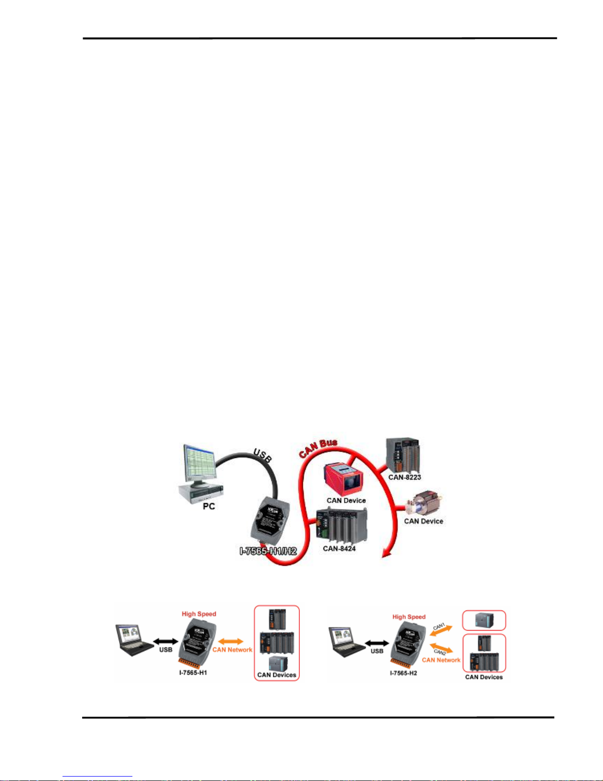
The following is the application for these two USB/CAN modules :
(1) I-7565-H1: High performance intelligent USB to 1- port CAN bus
Converter.
(2) I-7565-H2: High performance intelligent USB to 2- port CAN bus
Converter.
Figure 1-1: Application of I-7565-H1/H2
I-7565-H1 application I-7565-H2 application
I-7565-H1/H2 High Performance USB/CAN Converter User’s Manual (Ver 1.7, Aug/2011) ------------- 5

1.1 Features
• RoHS Design
• Fully compliant with USB 1.1/2.0 (Full Speed)
• Fully compatible with the ISO 11898-2 standard
• Support both CAN2.0A and CAN2.0B
• No external power supply (powered by USB)
• Integrated with one or two CAN bus interface
• Programmable CAN bus baud rate from 5Kbps to 1Mbps or user-
defined baud rate
• Support CAN bus acceptance filter configuration
• Support Listen Only Mode (LOM). (For FW v1.05 or newer)
• Support 5 sets of Hardware Send Timer for high precision CAN
messages sending. (For FW v1.05 or newer)
• Timestamp of CAN message with at least ±1ms precision
• Support firmware update via USB
• Provide utility tool for users module setting and CAN bus
communication testing conveniently
• Provide API library for user program development
• Provide Hardware Serial Number to protect users' program. (For FW
v1.04 or newer)
• Provide PWR / RUN / ERR indication LED
• Built-in jumper to select 120 ohm terminal resister
• Max data flow for CAN channel: 3000 fps ( depends on users’ PC
hardware performance )
• The CAN buffer is 256 data frames for I-7565-H1 and 128 data frames
in each CAN port for I-7565-H2.
• Watchdog inside
• Driver supported for Windows 2000/XP, Win7
(32/64bit) and WinCE
(available soon)
1.2 Specifications
[ USB specs: ]
• Input port : USB (USB Type B)
• Compatibility : USB 1.1 and 2.0 standard
• Driver Supported : Windows 2000/XP, Win7
(32/64bit) and WinCE
(available soon)
[ CAN specs: ]
I-7565-H1/H2 High Performance USB/CAN Converter User’s Manual (Ver 1.7, Aug/2011) ------------- 6

• CAN interface connector:
I-7565-H1 : 9-pin D-sub male
I-7565-H2 : 10-pin terminal-block
• CAN Baud Rate : 5K ~ 1Mbps or User-defined baud rate
• Isolation Voltage : 3000Vrms on the CAN side
[ Module specs: ]
• Dimensions : 108mm x 72mm x 35mm (H x W x D)
• Operating temperature : -25 to 75ºC (-13 to 167ºF);
• Storage temperature : -40 to 80ºC (-40 to 176ºF);
• Humidity : 5 to 95%, non-condensing;
• LEDs :
PWR LED for power
RUN LED for communication
ERR LED for error
[ Software Utility Tool / API Library: ]
• Provide CAN bus user-defined baud rate / acceptance filter
configuration
• Easily transmit / receive CAN messages for testing and display the
time-stamp of each received CAN message.
• Provide saving the CAN message as “TXT” file for data log.
• Provide sending CAN message by using the internal timer of module
for high precision transmission.
• Check / Reset module status remotely and get current CAN bus
message flow.
• Users can develop own program by API library quickly and easily.
[ Application: ]
• Factory Automation;
• Building Automation;
• Home Automation;
• Control system;
• Monitor system;
• Vehicle Automation;
I-7565-H1/H2 High Performance USB/CAN Converter User’s Manual (Ver 1.7, Aug/2011) ------------- 7

2. Hardware
Figure 2-1: Hardware externals of I-7565-H1/H2
2.1 Block Diagram
Figure 2-2 is a block diagram illustrating the functions on the I-7565H1/H2 module. It provides the 3000Vrms Isolation in the CAN interface
site.
Figure 2-2: Block diagram of I-7565-H1 / I-7565-H2
I-7565-H1/H2 High Performance USB/CAN Converter User’s Manual (Ver 1.7, Aug/2011) ------------- 8
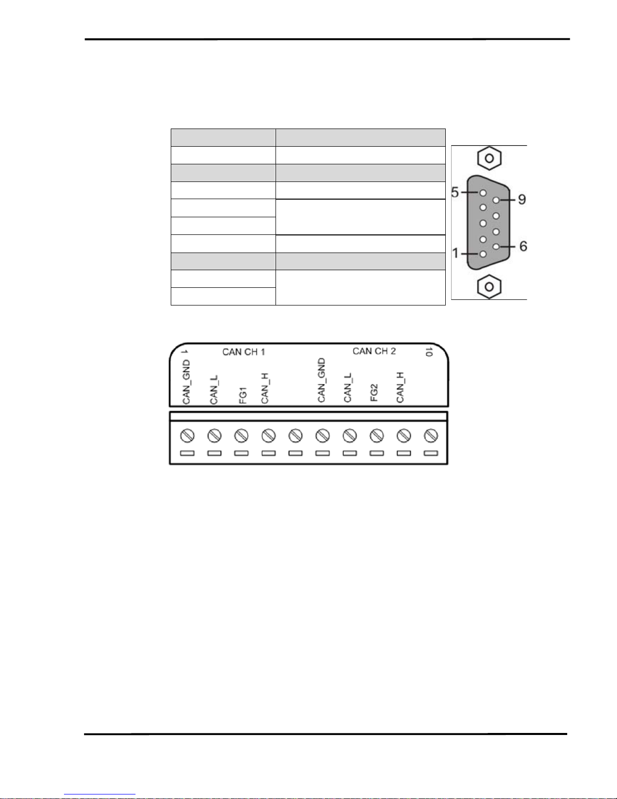
2.2 Pin Assignment of CAN Port
Table 1: CAN DB9 Male Connector on I-7565-H1
Terminal 2-wire CAN
1 Not Connect
2 CAN Low
3 CAN Ground
4
5
Not Connect
6 CAN Ground
7 CAN High
8
9
Not Connect
Figure 2-3: Pin Assignment on I-7565-H2
2.3 Hardware Connection
The pin assignment of the CAN port on the I-7565-H1 (DB9 male)
defined in both the CANopen DS102 profile and in appendix C of the
DeviceNet specifications. It is the standard pin assignment for CAN. The
hardware connection between device and I-7565-H1/H2 is like Figure 2-4.
I-7565-H1/H2 High Performance USB/CAN Converter User’s Manual (Ver 1.7, Aug/2011) ------------- 9

Figure 2-4: CAN Hardware Wire Connection
I-7565-H1/H2 High Performance USB/CAN Converter User’s Manual (Ver 1.7, Aug/2011) ------------- 10
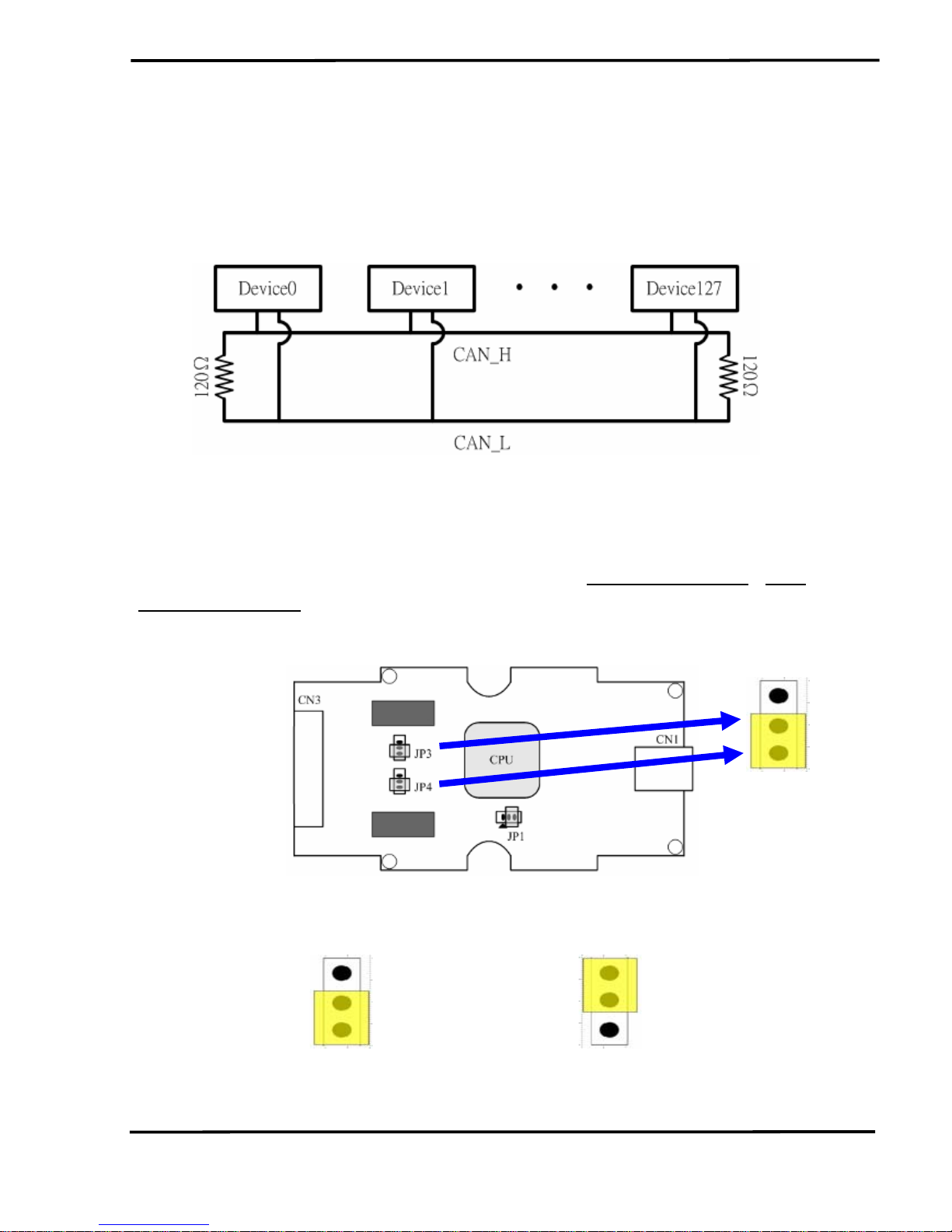
2.4 Terminator Resistor Settings
According to the ISO 11898 specifications, the CAN Bus network
must be terminated by two terminal resistors (120
Ω) for proper operation,
as shown in the below figure.
Figure 2-6: Terminal Resistor
Therefore, the I-7565-H1/H2 module supplies a jumper for users to
active the terminal resistor or not. If users want to use this terminal resistor,
please open the I-7565-H1/H2 cover and use the
JP3 for I-7565-H1 / JP3,
JP4 for I-7565-H2 to activate the 120Ω terminal resistor built in the module,
as the Figure 2-7. Note that the default setting is active.
Figure 2-7: Terminal Resistor Jumper
Enable (default), (Position: 1-2) Disable, (Position: 2-3)
Figure 2-8: JP3/JP4 Jumper Position
I-7565-H1/H2 High Performance USB/CAN Converter User’s Manual (Ver 1.7, Aug/2011) ------------- 11
2.5 Init / Normal Dip-switch
On the back of the I-7565-H1/H2 module, there is a dip-switch used
for
firmware operation or firmware updating of the module. The following
steps show how to use this dip-switch.
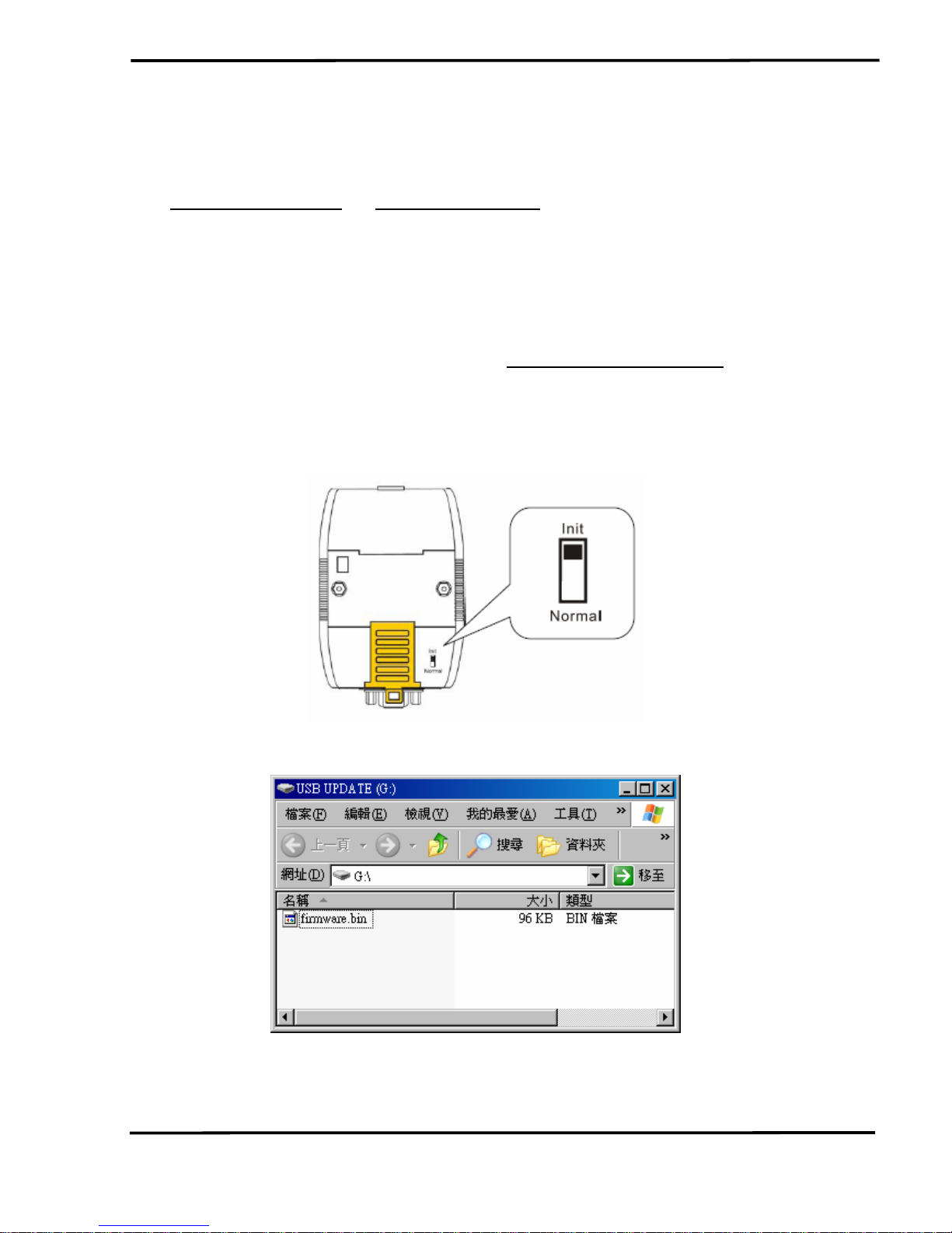
2.5.1 Firmware Update Mode
Please set the dip-switch to the “Init” (Initial) position like Figure 2-9.
Then the I-7565-H1/H2 will work in the “
Firmware Update Mode” after the
power of the module has been turned on again. In this mode, users can
update the firmware of the I-7565-H1/H2 module via USB and the module
will become a “USB Mass Storage Device” and also shows a folder like
Figure 2-10 automatically.
Figure 2-9: Init Position of Dip-Switch
Figure 2-10: USB Mass Storage Device
Users just need to execute “Firmware_Update_Tool.exe” and follow
I-7565-H1/H2 High Performance USB/CAN Converter User’s Manual (Ver 1.7, Aug/2011) ------------- 12
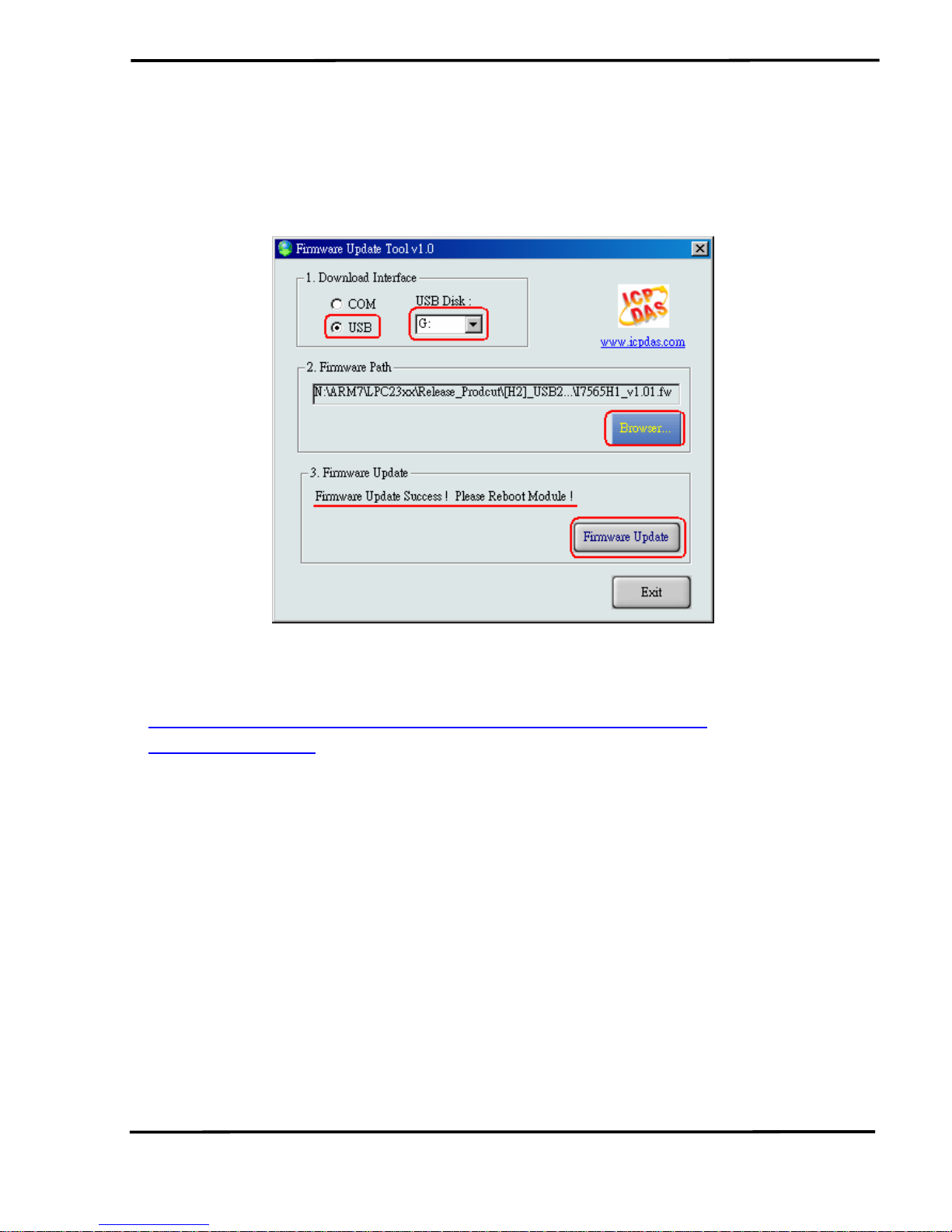
the below steps to complete the firmware updating process.
[1] Choose “USB” interface and “USB Disk”.
[2] Click “Browser” button to choose firmware file. (like I7565H1_v1.01.fw)
[3] Click “Firmware Update” button to start firmware updating process.
The result will show in “Firmware Update” field.
Figure 2-11: Normal Position of Dip-Switch
The Firmware_Update_Tool program can be downloaded from
http://ftp.icpdas.com/pub/cd/fieldbus_cd/can/converter/i-7565h1h2/software/tool
2.5.2 Firmware Operation Mode
In operation mode, users need to set the dip-switch to the “Normal”
position like Figure 2-12 and turn the power off then on again so that the I7565-H1/H2 can run in the operation mode. In this mode, users can send /
receive CAN messages via PC USB port.
I-7565-H1/H2 High Performance USB/CAN Converter User’s Manual (Ver 1.7, Aug/2011) ------------- 13
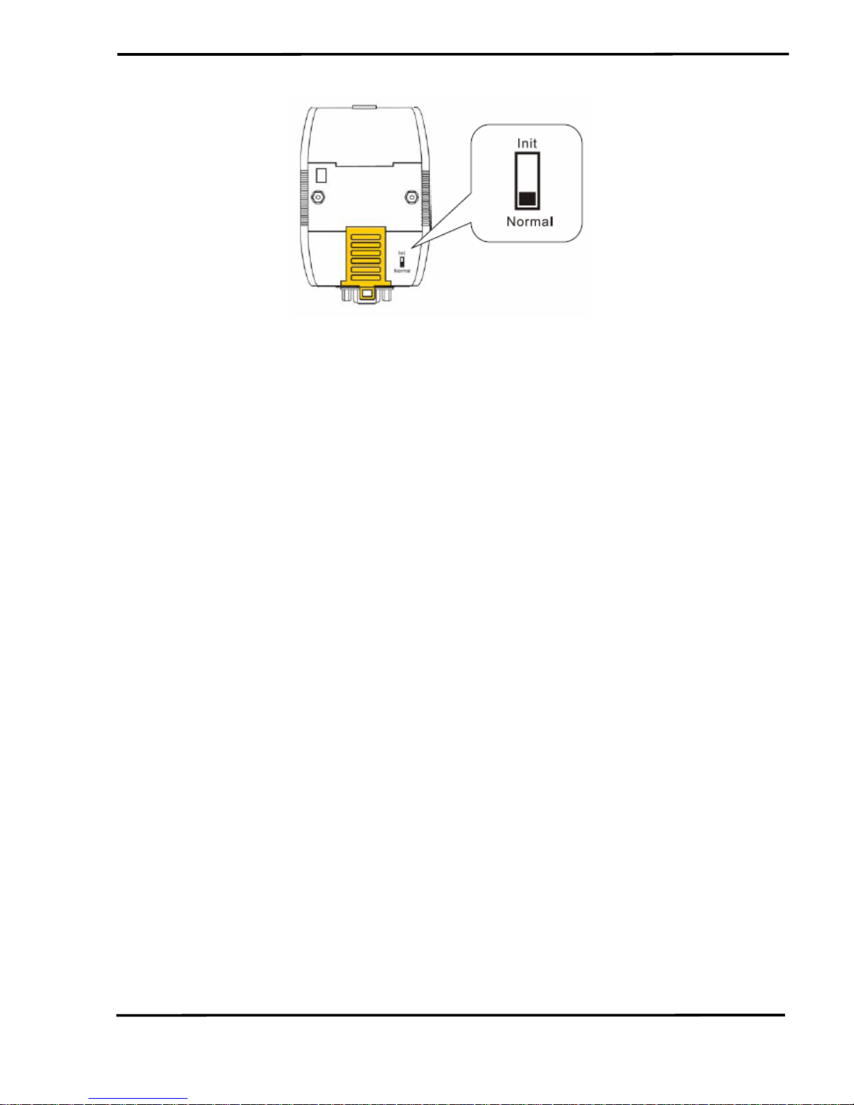
Figure 2-12: Normal Position of Dip-Switch
I-7565-H1/H2 High Performance USB/CAN Converter User’s Manual (Ver 1.7, Aug/2011) ------------- 14
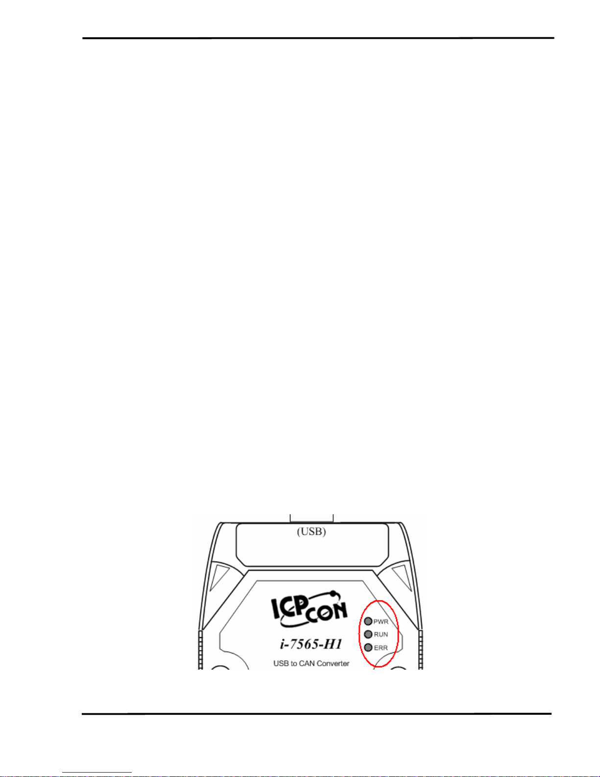
2.6 LED Indication
There are three LEDs provided to indicate to users what situation the
I-7565-H1/H2 is in. The following is the illustration of these three LEDs
and the position of these three LEDs shows as Figure 2-12.
(1) PWR LED :
It is used to help users to check whether the I-7565-H1/H2 is standby.
If the module is working in “firmware operation” mode, the PWR LED is
always turned on. However, when the module is working in the “firmware
updating” mode, the PWR LED will flash approximately once per second.
(2) RUN LED :
It is used to show whether the I-7565-H1/H2 is transmitting/receiving
CAN messages. The RUN LED will flash whenever a CAN message is
sending or receiving. In I-7565-H2, the RUN LED is shared by CAN1 port
and CAN2 port.
(3) ERR LED :
It is used for demonstrating an error that has occurred. The ERR LED
is normally turned off when the module works in a good condition. When
the Bus-Off error happened, the ERR LED will always turn on until the
Bus-Off condition disappeared. If the CAN/USB buffer built in I-7565H1/H2 overflows or CAN message can’t be sent out successfully, then the
ERR LED will flash continuously. In I-7565-H2, the ERR LED is shared by
CAN1 port and CAN2 port.
Figure 2-13: LED position of I-7565-H1/H2
I-7565-H1/H2 High Performance USB/CAN Converter User’s Manual (Ver 1.7, Aug/2011) ------------- 15
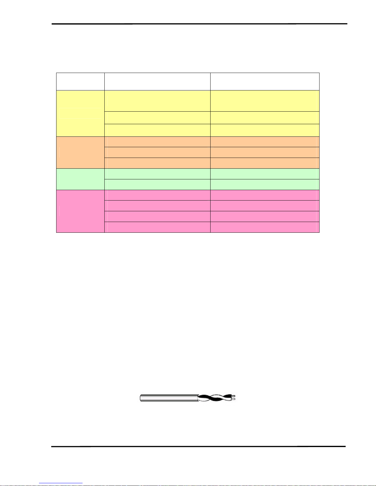
Table 2: LED indication of I-7565-H1/H2
LED Name I-7565-H1/H2 Status LED Status
Hardware Init Fail
All LED always turned on
permanently after reset
Hardware WDT Fail All LED flash per 2 second
ALL LED
Contact to ICP DAS All LED flash take turns
Firmware Updating Mode Flash per second
Firmware Operation Mode Always turned on
PWR LED
Power Off Off
Transmission Flash
RUN LED
Bus Idle Off
Transmission Fail Flash per 100 ms
Buffer Overflow Flash per second
Bus-Off Always turned on
ERR LED
No Error Off
2.7 Cable Selection
The CAN bus is a balanced (differential) 2-wire interface running over
either a Shielded Twisted Pair (STP), Un-shielded Twisted Pair (UTP), or
Ribbon cable. The CAN-L and CAN-H Wire start on one end of the total
CAN network that a terminator of 120 Ohm is connected between CAN-L
and CAN-H. The cable is connected from CAN node to CAN node,
normally without or with short T connections. On the other end of the cable
again a 120
Ω(Ohm) terminator resistor is connected between the CAN
lines. How to decide a cable type, cable length, and terminator depends
on the baud rate in the CAN bus network, please refer to the following
table 3.
Figure 2-14: Un-shielded Twisted Pair (UTP)
I-7565-H1/H2 High Performance USB/CAN Converter User’s Manual (Ver 1.7, Aug/2011) ------------- 16

Table 3: Cable selection
Bus speed Cable type
Cable
Resistance/m
Terminator Bus Length
50k bit/s
at 1000m
0.75~0.8mm2
18AWG
70 mOhm
150~300
Ohm
600~1000m
100k bit/s
at 500m
0.5~0.6 mm2
20AWG
< 60 mOhm
150~300
Ohm
300~600m
500k bit/s
at 100m
0.34~0.6mm2
22AWG, 20AWG
< 40 mOhm 127 Ohm 40~300m
1000k bit/s
at 40m
0.25~0.34mm2
23AWG, 22AWG
< 40 mOhm 124 Ohm 0~40m
Note: The AWG means a standard method used to measure wire. The
numbering system works backwards from what people would think, the
thicker (heavier) the wire, the lower the number. For example: a 24AWG
wire is thicker/heavier than a 26AWG wire.
I-7565-H1/H2 High Performance USB/CAN Converter User’s Manual (Ver 1.7, Aug/2011) ------------- 17
3. Driver Installation
This section will show how to install the I-7565-H1/H2 USB/CAN
converter device driver under Windows 2000/XP and Win7. Users can
download the I-7565-H1/H2 device driver from ICP DAS web site:
http://ftp.icpdas.com/pub/cd/fieldbus_cd/can/converter/i-7565-h1h2/driver.
Please follow the below steps to finish I-7565-H1/H2 driver installation.
3.1 Install I-7565-H1/H2 Driver by Auto
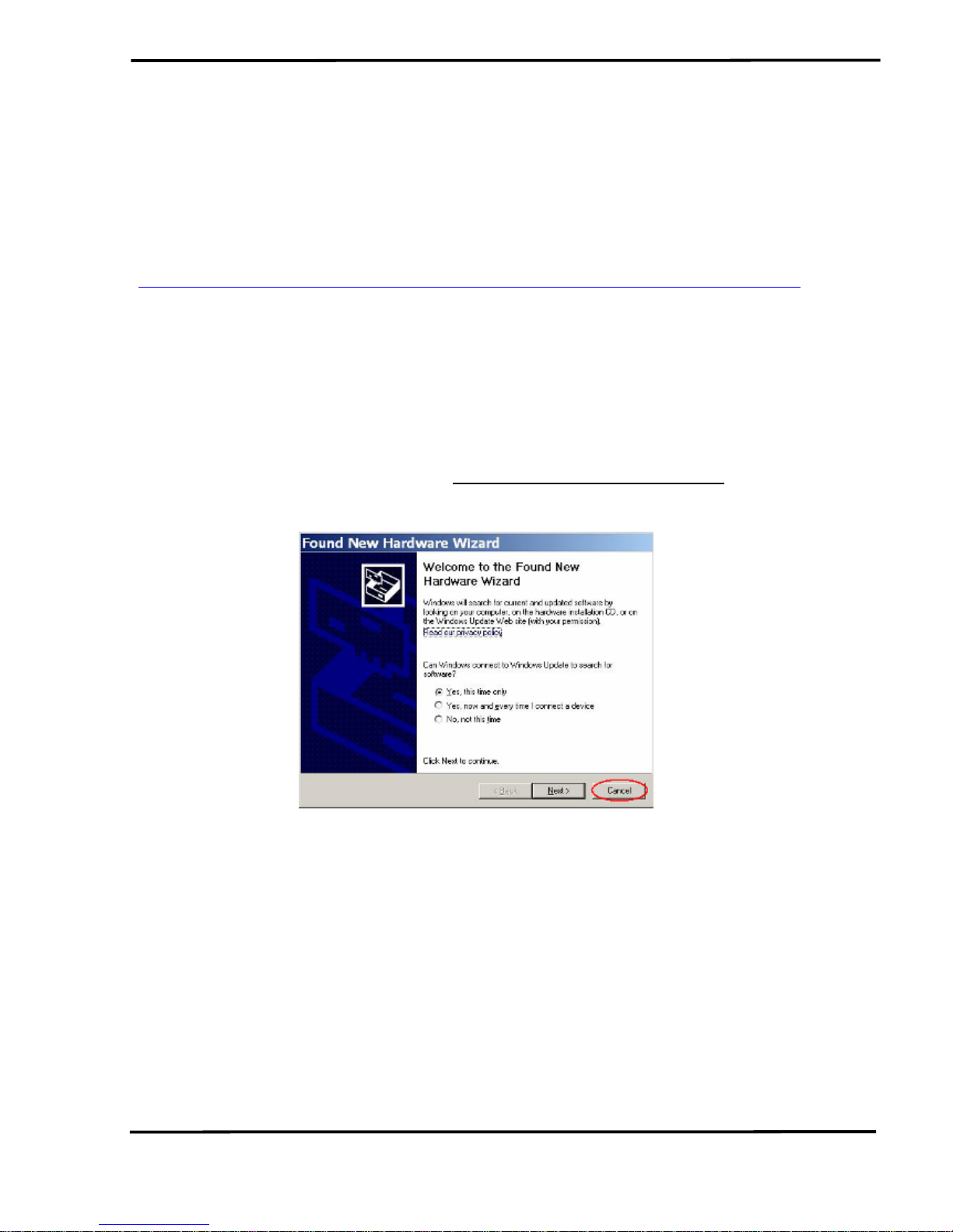
[ Step - 1 ]
Plug in the I-7565-H1 or I-7565-H2 to PC first and Windows will detect
the new device and shows the “
Found New Hardware Wizard” screen
prompting you to install the driver for the detected USB Device. Please
click “Cancel” button to cancel driver installation by manual like Figure 3-1.
Figure 3-1: New Hardware Wizard (1)
[ Step - 2 ]
Execute “I7565H1H2_DrvInst.exe“ file to install driver automatically
and then click “Continue Anyway” button like Figure 3-2. After driver
installation process finished, it will show the screen like Figure 3-3.
I-7565-H1/H2 High Performance USB/CAN Converter User’s Manual (Ver 1.7, Aug/2011) ------------- 18
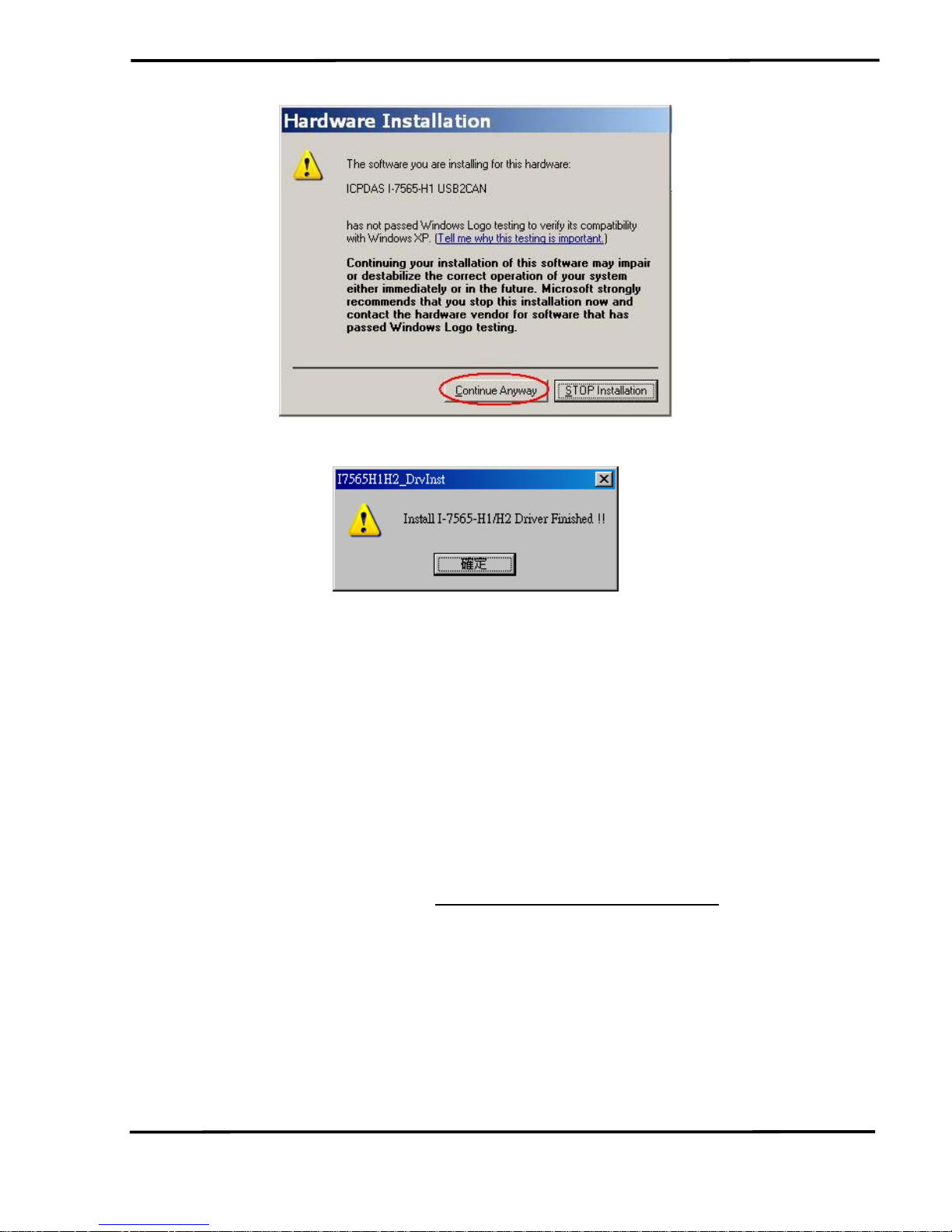
Figure 3-2: New Hardware Wizard (2)
Figure 3-3: Install I-7565-H1/H2 Driver Finished
3.2 Install I-7565-H1/H2 Driver by Manual
[ Step - 1 ]
Please execute “ICPUsbConverter_DrvInst.exe“ (the driver file name
for v1.2 or newer) file first to install necessary driver files of I-7565-H1/H2
to system.
[ Step - 2 ]
Plug in the I-7565-H1 or I-7565-H2 to PC and Windows will detect the
new device and shows the “
Found New Hardware Wizard” screen
prompting you to install the driver for the detected USB Device. Please
select “No, not this time” option and click “Next” button like Figure 3-4.
I-7565-H1/H2 High Performance USB/CAN Converter User’s Manual (Ver 1.7, Aug/2011) ------------- 19
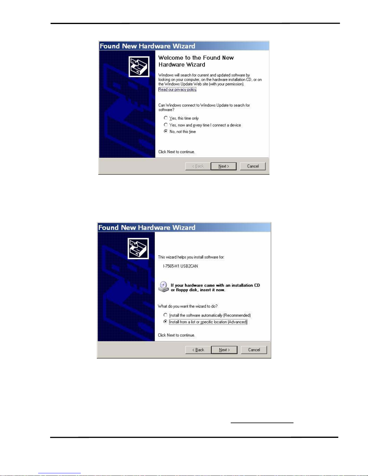
Figure 3-4: New Hardware Wizard (1)
[ Step - 3 ]
Please select “install from a list or specific location (Advanced)” option
and click “Next” button like Figure 3-5.
Figure 3-5: New Hardware Wizard (2)
[ Step - 4 ]
Please select “Search for the best driver in these locations” option and
check “include this location in the search:” checkbox and click “Browser”
button to assign the I-7565-H1/H2 driver location -
C:\WINDOWS\inf\ and
then click “Next” button like Figure 3-6.
I-7565-H1/H2 High Performance USB/CAN Converter User’s Manual (Ver 1.7, Aug/2011) ------------- 20
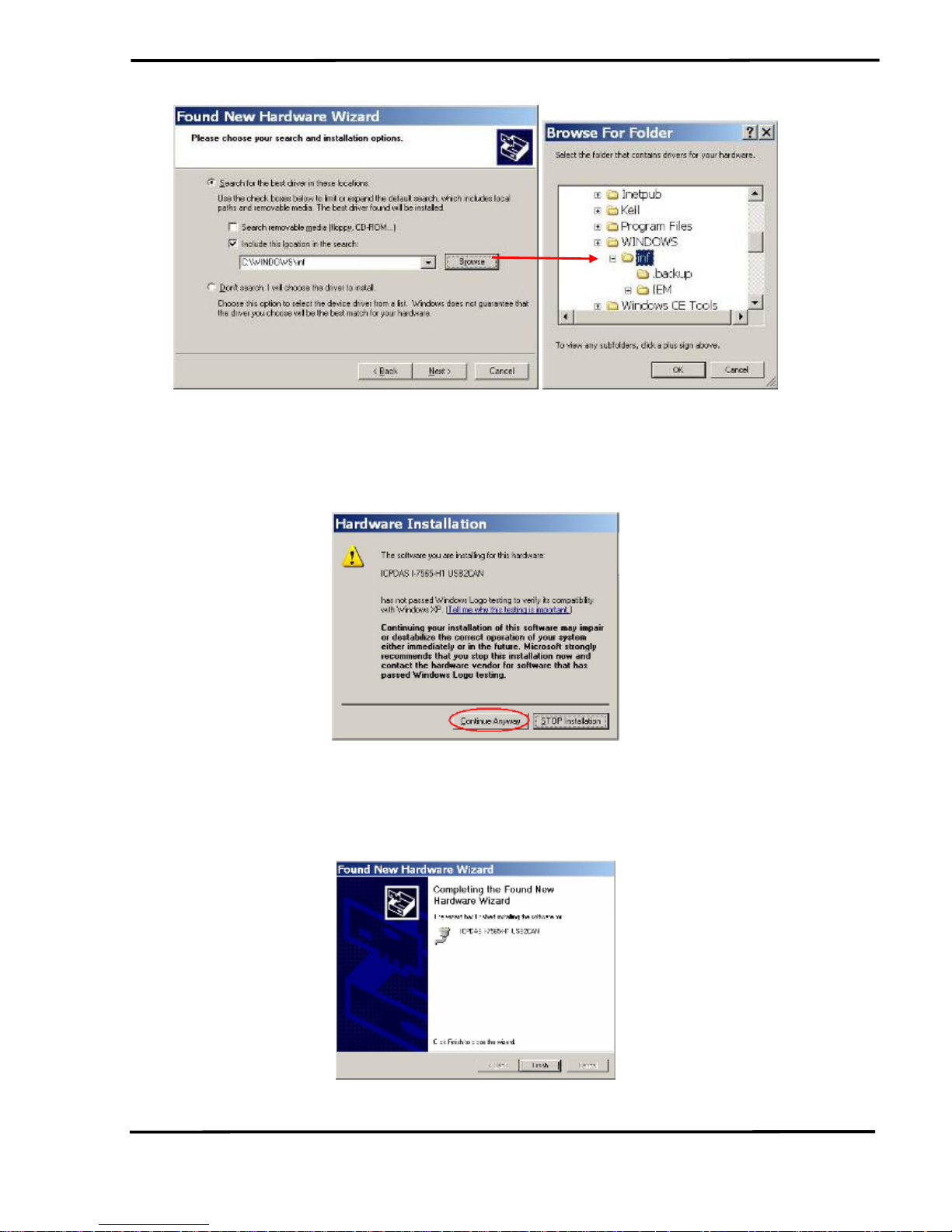
Figure 3-6: New Hardware Wizard (3)
[ Step - 5 ]
Please click “Continue Anyway” button like Figure 3-7 .
Figure 3-7: New Hardware Wizard (4)
[ Step - 6 ]
Please click “Finish” button to complete I-7565-H1/H2 device driver
installation like Figure 3-8.
Figure 3-8: New Hardware Wizard (5)
I-7565-H1/H2 High Performance USB/CAN Converter User’s Manual (Ver 1.7, Aug/2011) ------------- 21
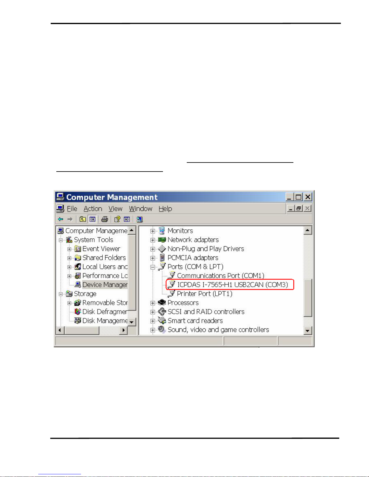
3.3 Verify Driver Installation
This section will show how to verify whether the driver of I-7565-H1/H2
was properly installed. If the driver is installed successfully, then there will
be a “Virtual COM Port” assigned by Windows. Please follow the below
steps to check it.
Click “Start” Æ “Settings” Æ “Control Panel” and then double click on
the “System” icon. Once the “System Properties” screen displayed, click
on ” Hardware” tab and then click on the “Device Manager” button.
Double-click on Ports (COM & LPT) item. If the device driver was
correctly installed, users can find the “
ICPDAS I-7565-H1 USB2CAN” or
“
ICPDAS I-7565-H2 USB2CAN” device listing and the “Virtual COM Port”
number that Windows has assigned to the device is COM3 like Figure 3-9.
Figure 3-9: Virtual COM Port Number
I-7565-H1/H2 High Performance USB/CAN Converter User’s Manual (Ver 1.7, Aug/2011) ------------- 22
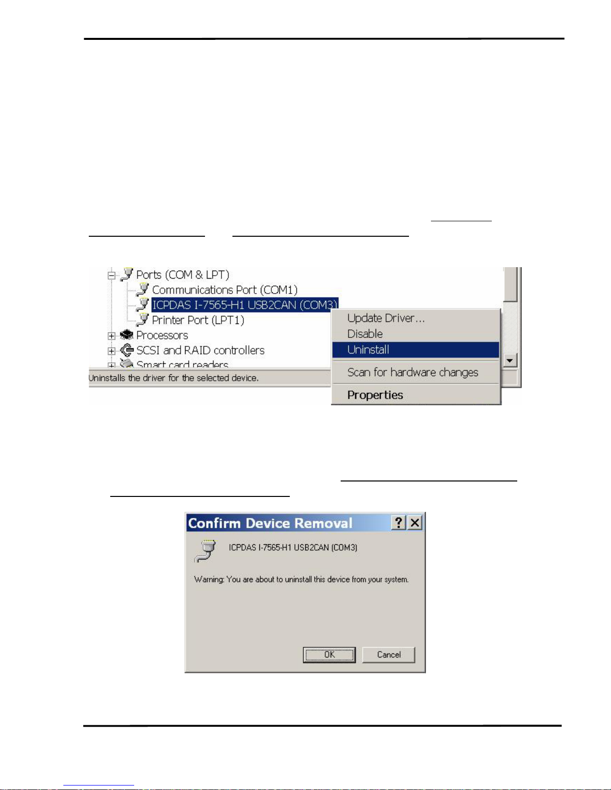
3.4 Uninstall I-7565-H1/H2 Driver
Please follow the below steps to uninstall I-7565-H1/H2 device driver.
[ Step - 1 ]
Click “Start” Æ “Settings” Æ “Control Panel” and then double click on
the “System” icon. Once the “System Properties” screen displayed, click
on ” Hardware” tab and then click on the “Device Manager” button.
Double-click on Ports (COM & LPT) item. Please find the “
ICPDAS I-
7565-H1 USB2CAN” or “ICPDAS I-7565-H2 USB2CAN” device listing and
right click mouse button on it and choose “Uninstall” item like Figure 3-10.
Figure 3-10: Uninstall I-7565-H1/H2 Driver (1)
[ Step - 2 ]
Click “OK” button to complete I-7565-H1/H2 device driver un-
installation like Figure 3-11. After that, the “
ICPDAS I-7565-H1 USB2CAN”
or “
ICPDAS I-7565-H2 USB2CAN” device listing will disappear on Ports
(COM & LPT) item.
Figure 3-11: Uninstall I-7565-H1/H2 Driver (2)
I-7565-H1/H2 High Performance USB/CAN Converter User’s Manual (Ver 1.7, Aug/2011) ------------- 23
4. Software Utility
I-7565-H1/H2 Utility is provided by ICP DAS to transmit / receive CAN
messages for CAN bus communication testing easily and quickly. In the
meanwhile, it can also display the time-stamp of each received CAN
message for data analyzing conveniently. I-7565-H1/H2 Utility can be
downloaded from the ICP DAS web site :
http://ftp.icpdas.com/pub/cd/fieldbus_cd/can/converter/i-7565h1h2/software/utility. The following is the main functions provided by I-
7565-H1/H2 Utility :
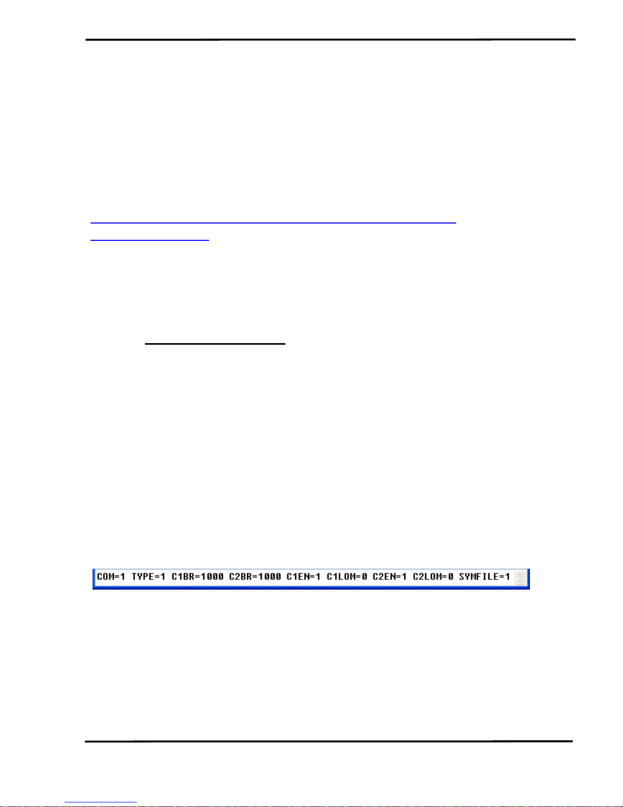
4.1 INI File Function
Whenever users execute the I-7565-H1/H2 Utility, it will look for the
INT file :
I-7565-H1H2_Utility.ini first to load the initial connection setting.
If the INI file doesn’t exist, then it will load the default setting. The below is
the format illustration of the INI file like Figure 4-1.
[1] COM : The Virtual COM Port Number.
[2] TYPE : 1: I-7565-H1; 2: I-7565-H2.
[3] C1BR : CAN1 Baud Rate
[4] C2BR : CAN2 Baud Rate
[5] C1EN : CAN1 Port Function. (1: Enable; 0: Disable)
[6] C2EN : CAN2 Port Function. (1: Enable; 0: Disable)
[7] C1LOM : CAN1 Listen Only Mode (1: Enable; 0: Disable)
[8] C2LOM : CAN2 Listen Only Mode (1: Enable; 0: Disable)
[9] SYMFILE: Load Symbol Initial File (I-7565-H1H2_SymFile.ini)
Automatically (1: Enable; 0: Disable) => Supported in
Utility v1.10
Figure 4-1: INI file Parameters of I-7565-H1/H2 Utility
4.2 Connection Function
When users execute the I-7565-H1/H2 Utility, it will show connection
function screen first for connecting to I-7565-H1/H2 like Figure 4-2. The
following is the illustration for connection parameters.
[1] Com Port : The Virtual COM Port Number.
I-7565-H1/H2 High Performance USB/CAN Converter User’s Manual (Ver 1.7, Aug/2011) ------------- 24
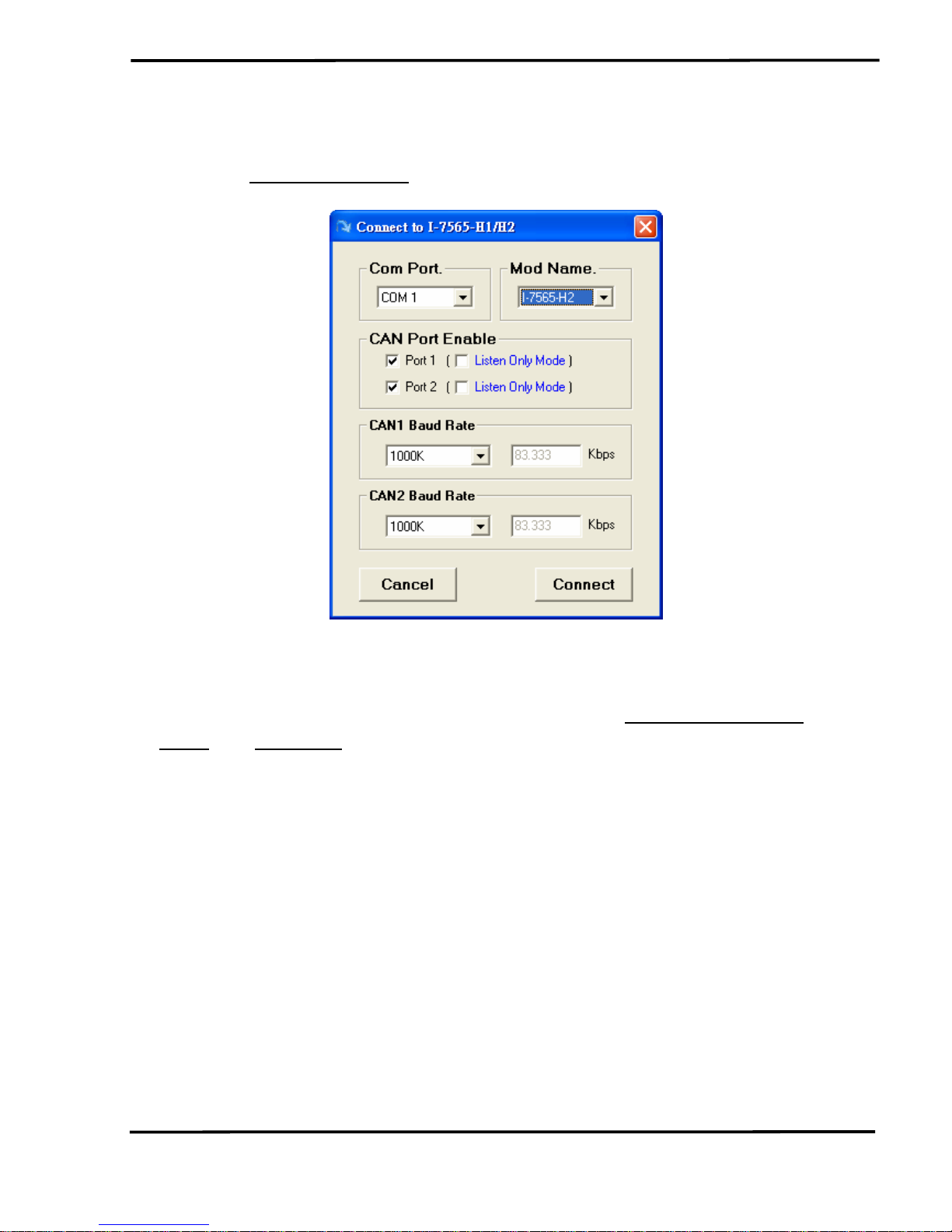
[2] Mod Name : The Module Name.
[3] CAN Port Enable : Enable CAN Port Function. (Checked: Enable)
(3.1)
Listen Only Mode : Enable Listen Only mode
[4] CAN Baud Rate : CAN bus Baud Rate Setting.
Figure 4-2: Connection Screen of I-7565-H1/H2 Utility
[ Note ]
1. “Listen Only Mode” (LOM) function is supported by
I-7565-H1/H2 Utility
v1.09 and FW v1.05 or newer. The LOM screen is like Figure 4-2-1. (In
LOM, CAN message sending function is disabled.)
I-7565-H1/H2 High Performance USB/CAN Converter User’s Manual (Ver 1.7, Aug/2011) ------------- 25
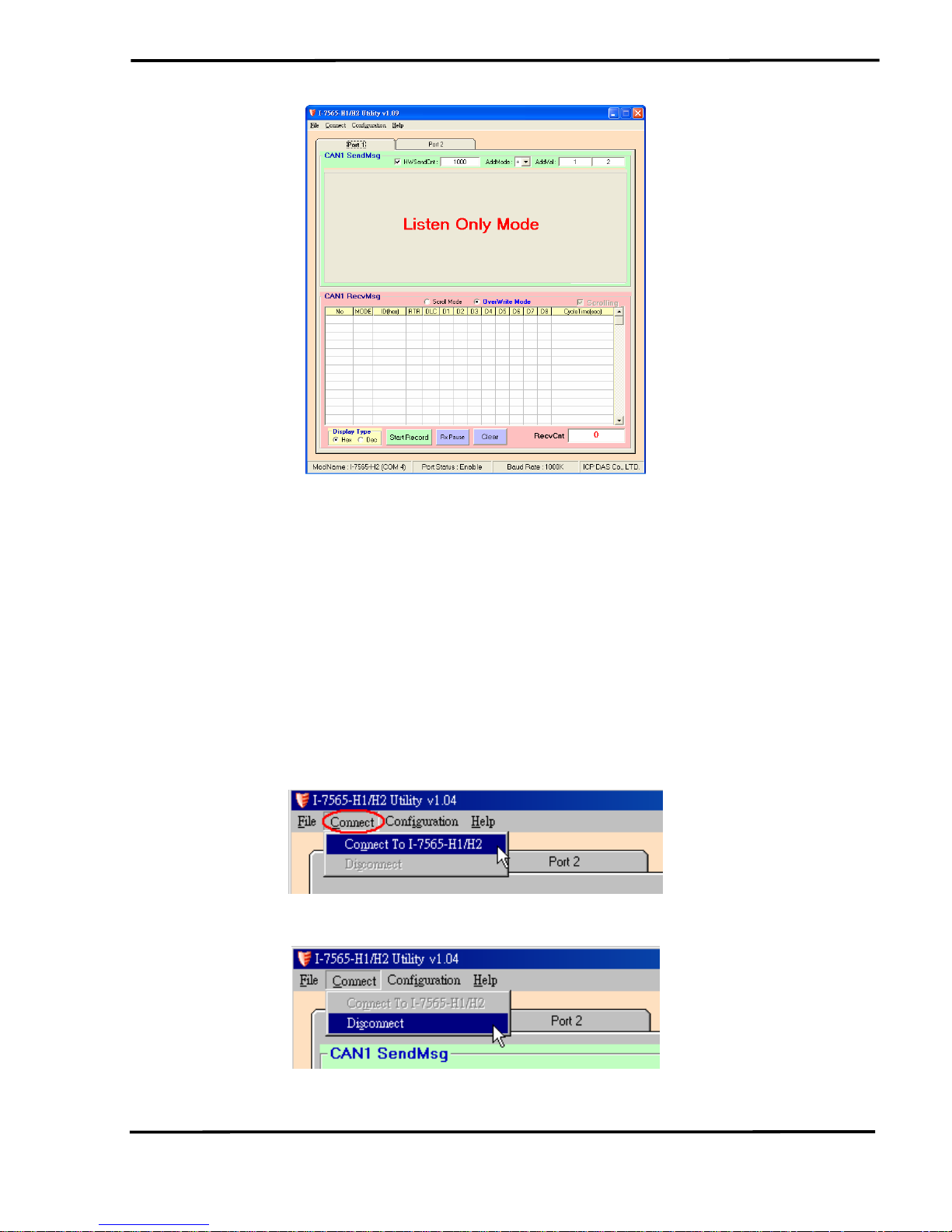
Figure 4-2-1: LOM Screen of I-7565-H1/H2 Utility
After finish the connection setting, please click “Connect” button to
connect to I-7565-H1/H2 module. Note that I-7565-H1/H2 doesn’t affect
the CAN bus communication when power on because the CAN port
function will keep disabled until users connect to I-7565-H1/H2
successfully. As soon as users disconnect to I-7565-H1/H2, the CAN port
function on I-7565-H1/H2 will be disabled again. Besides, users can also
click “Connect” item in the menu bar and choose “Connect To I-7565H1/H2” function to connect to I-7565-H1/H2 like Figure 4-3 or “Disconnect”
function to disconnect to I-7565-H1/H2 like Figure 4-4.
Figure 4-3: “Connect To I-7565-H1/H2” function
Figure 4-4: “Disconnect” function
I-7565-H1/H2 High Performance USB/CAN Converter User’s Manual (Ver 1.7, Aug/2011) ------------- 26

4.3 Communication Function
If the connection to I-7565-H1/H2 is successful, then the screen for
CAN bus communication function will show up like the Figure 4-5.
Figure 4-5: Communication Screen of I-7565-H1/H2 Utility
The following is the illustration for the communication screen and it
can be divided to two blocks in each CAN port function. One is “SendMsg”
block and the other is “RecvMsg” block. Besides, “Port 1” / “Port 2” tab is
used to switch CAN1 / CAN2 communication screen.
I-7565-H1/H2 High Performance USB/CAN Converter User’s Manual (Ver 1.7, Aug/2011) ------------- 27
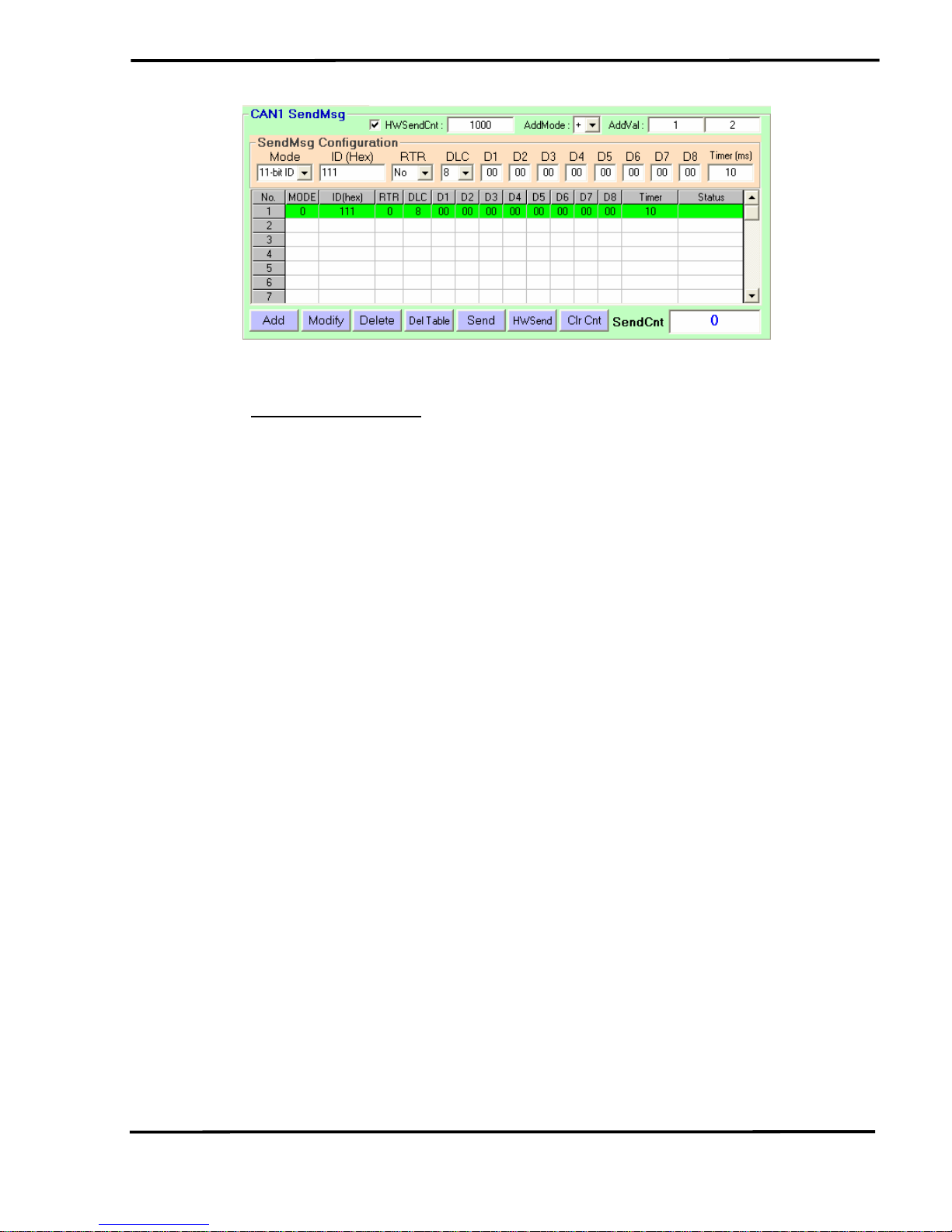
Figure 4-6-1: Send CAN Message Area
[1] For “
CAN1/2 SendMsg” block :
<1> “SendMsg Configuration” frame :
It is used to edit the CAN message parameters and users can
use “Add” button to add the CAN message to “CAN Message
Send Area”.
<2> “Add” button :
It will add the CAN message from “SendMsg Configuration”
area to the last row in “CAN Message Send Area”.
<3> “Modify” button :
It will modify the CAN message parameter from “SendMsg
Configuration” area to the assigned green row in “CAN
Message Send Area”.
<4> “Delete” button :
It will delete the CAN message of the assigned green row in
“CAN Message Send Area”.
<5> “Del Table” button :
It will delete all the CAN messages in “CAN Message Send
Area”.
<6> “Send” button :
It will send the CAN message of the assigned green row in
“CAN Message Send Area”. If the value in the “Timer” field is
zero, it will just send once. If not, it will send continuously by
PC timer.
<7> “HWSend” button :
It will send the CAN message of the assigned green row in
“CAN Message Send Area”. If the value in the “Timer” field is
zero, it will just send once. If not, it will send continuously by
I-7565-H1/H2 High Performance USB/CAN Converter User’s Manual (Ver 1.7, Aug/2011) ------------- 28
module hardware timer and it will be more precise than PC
timer. If users want to send the CAN message with fixed
number, then before clicking “HWSend” button, please check
the “HWSendCnt” checkbox first and input the count in the
field like Figure 4-6-1.
In “AddMode” field, it is used to set the CAN Data value
addition mode. The ‘n’ option is “disable” mode, the ‘+’ option
is “addition” mode and the ‘x’ option is “multiple” mode. In
“AddVal” field, the first field is used for CANL Data and the
second field is used for CANH Data.
<8> “Clr Cnt” button :
It will clear the “SendCnt” value to be zero in “CAN Message
Send Area”.
<9> “SendCnt” field :
Whenever the CAN message is sent out once, the “SendCnt”
value will be added by 1 except “HWSend” function.
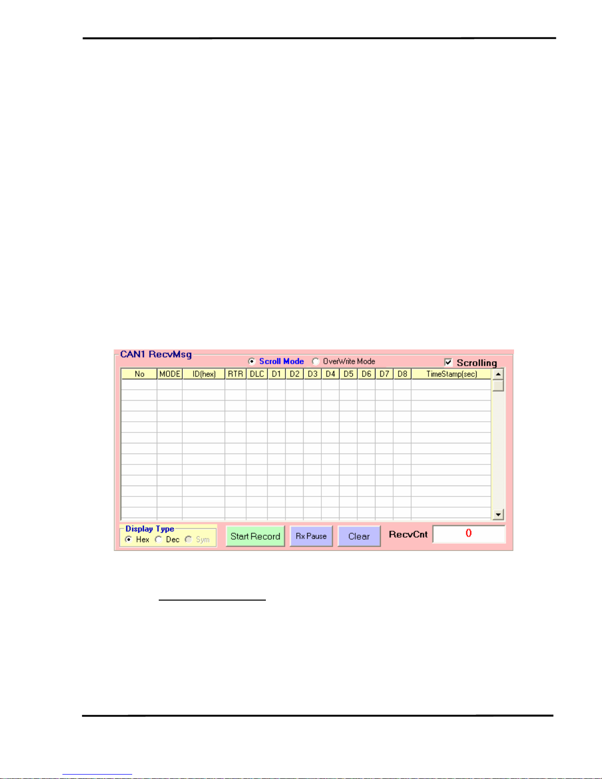
Figure 4-6-2: Recv CAN Message Area
[2] For “
CAN1/2 RecvMsg” block :
<1> “Display Type” option :
Hex : Used to show the ID and Data with “Hex“ format in
“CAN Message Receive Area”.
Dec : Used to show the ID and Data with “Decimal“ format in
“CAN Message Receive Area”.
Sym : Used to show the ID with “Symbolic Name“ in “CAN
I-7565-H1/H2 High Performance USB/CAN Converter User’s Manual (Ver 1.7, Aug/2011) ------------- 29
 Loading...