

ICPDAS I-7540D-WF User Manual
I-7540D-WF CAN to Wi-Fi Converter User’s Manual (Ver. 2.0, Jan/2012) ------------- 1
User’s Manual
www.icpdas.com
I-7540D-WF
CAN to Wi
-
Fi Converter

I-7540D-WF CAN to Wi-Fi Converter User’s Manual (Ver. 2.0, Jan/2012) ------------- 2
Warranty
All products manufactured by ICP DAS are under warranty regarding
defective materials for a period of one year from the date of delivery to the
original purchaser.
Warning
ICP DAS assumes no liability for damages resulting from the use of
this product. ICP DAS reserves the right to change this manual at any time
without notice. The information furnished by ICP DAS is believed to be
accurate and reliable. However, no responsibility is assumed by ICP DAS
for its use, or for any infringements of patents or other rights of third
parties resulting from its use.
Copyright
Copyright 2011 by ICP DAS. All rights are reserved.
Trademark
The names used for identification only may be registered trademarks
of their respective companies.
Document Revision
Version Author Date Description of changes
1.0 T.H. 2011-04-26 First Release Revision
1.1 T.H. 2011-12-13
Update images of module
appearance
2.0 T.H. 2012-01-02
Add CAN ID Filter function
description

I-7540D-WF CAN to Wi-Fi Converter User’s Manual (Ver. 2.0, Jan/2012) ------------- 3
Table of Contents
1. Introduction.......................................................................................5
1.1 Operation Mode................................................................................. 6
1.2 Features............................................................................................. 6
1.3 Specifications..................................................................................... 6
2. Hardware ...........................................................................................8
2.1 Block Diagram.................................................................................... 8
2.2 Pin Assignment.................................................................................. 9
2.3 Hardware Connection ........................................................................ 9
2.3.1 CAN port connection........................................................................ 9
2.3.2 Serial port connection..................................................................... 10
2.4 Terminator Resistor Settings.............................................................11
2.5 Watchdog Timer Settings................................................................. 12
2.6 Init / Normal Dip-switch.................................................................... 12
2.6.1 Firmware Update Mode.................................................................. 12
2.6.2 Firmware Operation Mode.............................................................. 15
2.7 LED Indication.................................................................................. 16
2.8 Seven-segment display.................................................................... 18
2.8.1 Title Description.............................................................................. 18
2.8.2 The contents of Parameter............................................................. 19
2.9 Cable Selection................................................................................ 20
3. Software...........................................................................................22
3.1 Connection and Configuration Tool – I-7540D-WF Utility................. 22
3.2 I-7540D-WF Utility............................................................................ 23
3.2.1 Connection Settings Screen........................................................... 23
Basic Parameter configuration......................................................... 23
CAN Baud Rate configuration.......................................................... 24
Network configuration ...................................................................... 24
Wi-Fi configuration........................................................................... 25
Parameter Transmission Interface................................................... 26
Parameter Transmission status bar.................................................. 26
Display Firmware Information .......................................................... 27
Parameter reading function.............................................................. 27
Parameter writing function ............................................................... 27
Exit parameter setting...................................................................... 27
3.2.2 CAN ID Filter Settings Screen........................................................ 28
Single ID frame................................................................................ 28
Group ID frame................................................................................ 28

I-7540D-WF CAN to Wi-Fi Converter User’s Manual (Ver. 2.0, Jan/2012) ------------- 4
Get Accepted ID button.................................................................... 29
Set Accepted ID button.................................................................... 29
Add button........................................................................................ 29
Del button......................................................................................... 29
3.2.3 Main Screen................................................................................... 30
4. Application Notes............................................................................36
4.1 Hardware Installation ....................................................................... 37
4.2 I-7540D-WF connection mode......................................................... 38
4.2.1 Server connection mode ................................................................ 38
4.2.2 Client connection mode.................................................................. 39
4.3 Connection test................................................................................ 41
4.3.1 Two I-7540D-WF connection application architecture.................... 41
4.3.2 I-7540D-WF and PC connection application architecture............... 42
5. Troubleshooting..............................................................................45
I-7540D-WF CAN to Wi-Fi Converter User’s Manual (Ver. 2.0, Jan/2012) ------------- 5
1. Introduction
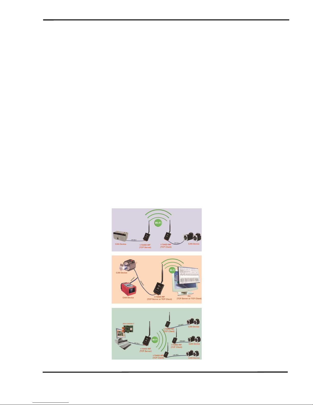
The I-7540D-WF supports the wireless transmission of CAN data
between various CAN networks or a CAN network and a WLAN network
according to the 802.11b/g standard. It is highly suitable for connecting
mobile (e.g., vehicles or machines) or stationary CAN networks and is
often used for short ranges up to 100 m.(TCP data protocols are available.)
Using an appropriately configured router, CAN data can be transmitted
over the Internet. There are two operating modes in the I-7540D-WF: the
access point mode and the ad-hoc mode. In the access point mode, the
data connection takes place over one or several WLAN access points that
are often part of the company's internal IT infrastructure. In the ad-hoc
mode, a direct connection is established between a single I-7540D-WF
device and a PC or laptop (with an integrated WLAN interface), or with a
second I-7540D-WF device. In this way, the I-7540D-WF can be used as a
CAN diagnosis interface. The wireless connection that is established
between two I-7540D-WF units can be used instead of a cable, and
enables the connection of CAN networks that would otherwise be difficult
to link such as rotational machinery.
Figure 1-1: Application architecture for the I-7540D-WF

I-7540D-WF CAN to Wi-Fi Converter User’s Manual (Ver. 2.0, Jan/2012) ------------- 6
1.1 Operation Mode
I-7540D-WF provides wireless data transmission of CAN, and
supports AP and Ad-hoc operation modes of WLAN.
1.2 Features
• RoHS Design
• IEEE 802.11b/g compliant
• Built-in jumper to select 120 ohm terminal resister of CAN bus
• Watchdog inside
• Wireless data transmission via WLAN
• Support two operation modes: Infrastructure mode and Ad-hoc mode
• Support point to point or point to multi-points connection via WLAN
• Support WEP, WPA and WPA2 encryption for WLAN
• CAN 2.0A/2.0B compliant
• Support CAN bus acceptance filter configuration
• Communication efficiency(peak value): one-way is up to 700 fps (client-
>server, server->client),two-way 350 fps (client<=>server)
• Wireless transmission distance: up to 100 meters
1.3 Specifications
[ UART Specs: ]
• Connector : 10-pin screw terminal connector(Pin1/ Pin2/ Pin3)
• COM1 : RS-232(TXD, RXD, GND)
• Baud Rate (bps) : 115200
[ CAN Specs: ]
• Connector : 10-pin screw terminal connector(Pin5/ Pin6/ Pin7)
• CAN Baud Rate : 5K ~ 1Mbps
• Isolation Voltage : 3000 VDC power protection on CAN side, 2500Vrms
photo-couple isolation on CAN bus
• Terminator Resistor: Selectable 120Ω terminator resistor by jumper
• Specification; ISO-11898-2, CAN 2.0A and CAN 2.0B
[Wireless Specs: ]
• Standard Supported : IEEE 802.11b & IEEE 802.11g
• Frequency Range : 2.412GHz ~ 2.484GHz
• Center Frequencies:Europe – 2.412GHz ~ 2.472GHz
USA – 2.412GHz ~ 2.462GHz
• Channels:
Europe – 13 channels

I-7540D-WF CAN to Wi-Fi Converter User’s Manual (Ver. 2.0, Jan/2012) ------------- 7
USA – 11 channels
[Antenna Specs: ]
• Connector : RP SMA Male (Plug)
• Radiation : Omni-Directional
• Band : 2.4 ~ 2.5GHz
• Gain : 5 dBi
[ Module Specs: ]
• Dimensions : 117mm x 76mm x 37mm (H x W x D)
• Operating temperature : -25 ~ 75ºC (-13 ~ 167ºF)
• Storage temperature : -30 ~ 80ºC (-40 ~ 176ºF)
• Humidity : 10 to 90%, non-condensing
• LEDs : PWR LED - Power indicator
Wi-Fi LED - Wi-Fi communication indicator
CAN LED - CAN communication indicator
WLAN LED - WLAN connection indicator
CNT. LED - TCP connection indicator
[ Utility Tool: ]
• Provide WLAN connection and configuration interface
• Provide WLAN encryption configuration interface
• Provide CAN bus acceptance filter configuration interface
•
Provide CAN messages transmission / reception interface
[ Application: ]
• Factory Automation
• Building Automation
• Home Automation
• Control System
• Monitor System
• Vehicle Automation
I-7540D-WF CAN to Wi-Fi Converter User’s Manual (Ver. 2.0, Jan/2012) ------------- 8
2. Hardware
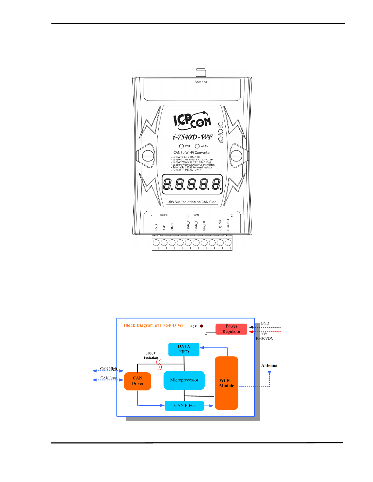
Figure 2-1: Hardware externals of the I-7540D-WF
2.1 Block Diagram
Figure 2-2 is a block diagram illustrating the functions on the I-7540DWF module. It provides the 3000Vrms Isolation in the CAN interface site.
Figure 2-2: Block diagram of the I-7540D-WF

I-7540D-WF CAN to Wi-Fi Converter User’s Manual (Ver. 2.0, Jan/2012) ------------- 9
2.2 Pin Assignment
Figure 2-3: Pin Assignment on the I-7540D-WF
2.3 Hardware Connection
I-7540D-WF module supports the CAN data wireless communications,
it provides a wireless link interface for CAN network, and the RS-232
interface provides to configuration the parameter of product.
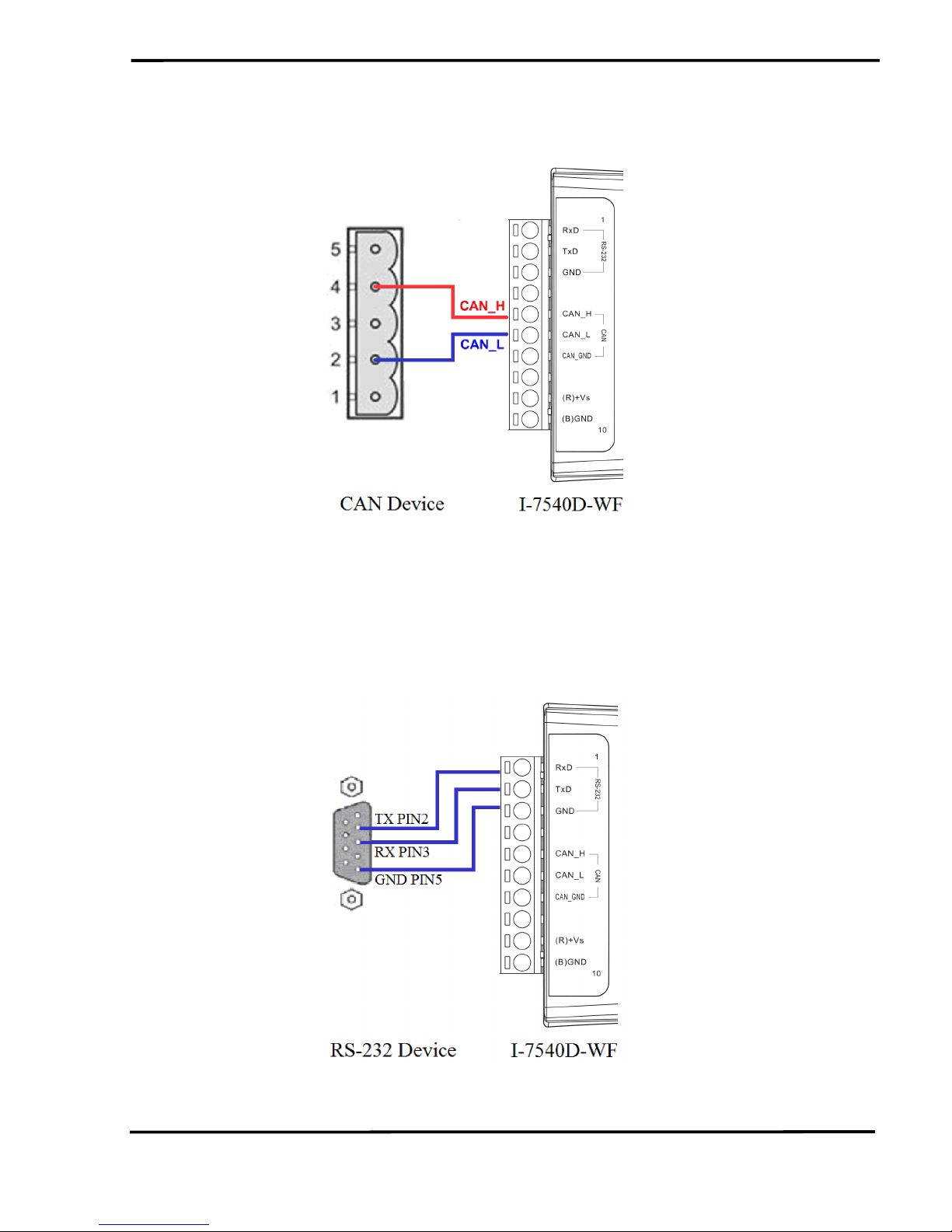
2.3.1 CAN port connection
The hardware connection between device and the I-7540D-WF is as
Figure 2-4.
Table 2-1: 10-pin screw terminal connecter
10-pin screw terminal connecter
Pin Description
1 RS-232 RXD
2 RS-232 TXD
3 RS-232 GND
4
Not Connect
5
CAN_H
6
CAN_L
7
CAN_GND
8
Not Connect
9 +Vs(+10 ~ +30 VDC)
10 GND
I-7540D-WF CAN to Wi-Fi Converter User’s Manual (Ver. 2.0, Jan/2012) ------------- 10
Figure 2-4: CAN Hardware Wire Connection
2.3.2 Serial port connection
The I-7540D-WF offers RS-232 serial interfaces to the user. The
following figures describe the COM port to a serial device via serial
network.
Figure 2-5: RS-232 Wire Connection
I-7540D-WF CAN to Wi-Fi Converter User’s Manual (Ver. 2.0, Jan/2012) ------------- 11
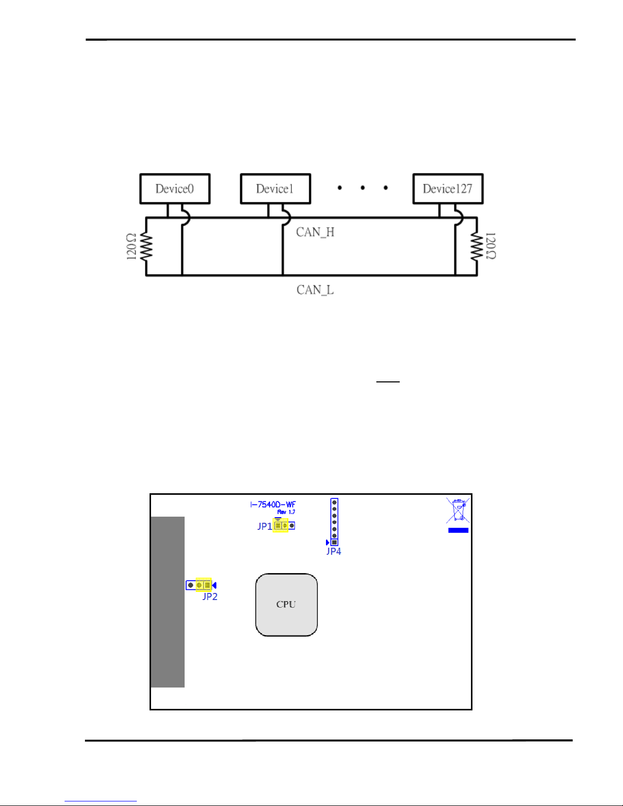
2.4 Terminator Resistor Settings
According to the ISO 11898 specifications, the CAN Bus network
must be terminated by two terminal resistors (120Ω) for proper operation,
as shown in the following figure.
Figure 2-6: Terminal Resistor
Therefore, the I-7540D-WF module supplies a jumper for users to
active the terminal resistor or not. If users want to use this terminal resistor,
please open the I-7540D-WF cover and use the JP2 to activate the 120
Ω
terminal resistor built in the module, as the Figure 2-7. Note that the
default setting is active.
The purpose of the terminal resistor is used to terminate the electrical
signal, in order to avoid reflected signals interfere with the normal signal
transduction. If the I-7540D-WF is not in the terminal at the CAN network,
the termination resistors should not be enabled.
Figure 2-7: Terminal Resistor Jumper
I-7540D-WF CAN to Wi-Fi Converter User’s Manual (Ver. 2.0, Jan/2012) ------------- 12
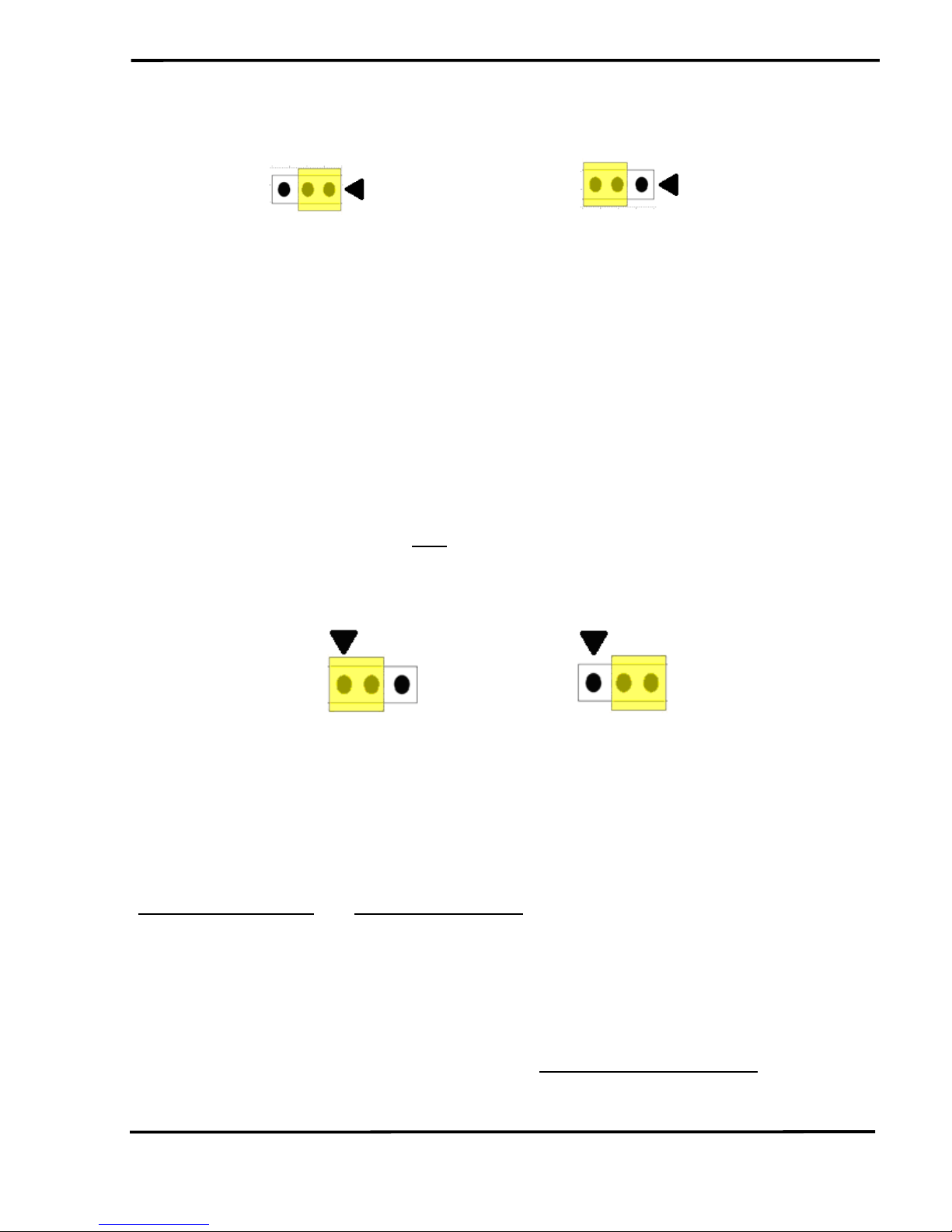
Enable (default) Disable
Figure 2-8: Terminal resistor JP2 Jumper Position
2.5 Watchdog Timer Settings
A watchdog timer (WDT) is a device that performs a specific
operation after a certain period of time if something goes wrong and the
system does not recover on its own. A watchdog timer can perform a
warm boot(restarting the system) after a certain number of milliseconds.
The I-7540D-WF module supplies a jumper for users to active the
watchdog timer or not. If users want to use this WDT, can open the I7540D-WF cover and use the JP1 to activate the WDT built in the module,
as the Figure 2-7. Note that the default setting is active.
Enable (default) Disable
Figure 2-9: Watchdog timer JP1 Jumper Position
2.6 Init / Normal Dip-switch
On the back of the I-7540D-WF module, there is a dip-switch used for
firmware operation or firmware updating of the module. The following
steps show how to use this dip-switch.
2.6.1 Firmware Update Mode
Please set the dip-switch to the “Init” (Initial) position as Figure 2-10,
and then the I-7540D-WF will work in the “Firmware Update Mode” after
reset the power of the module. In this mode, users can update the
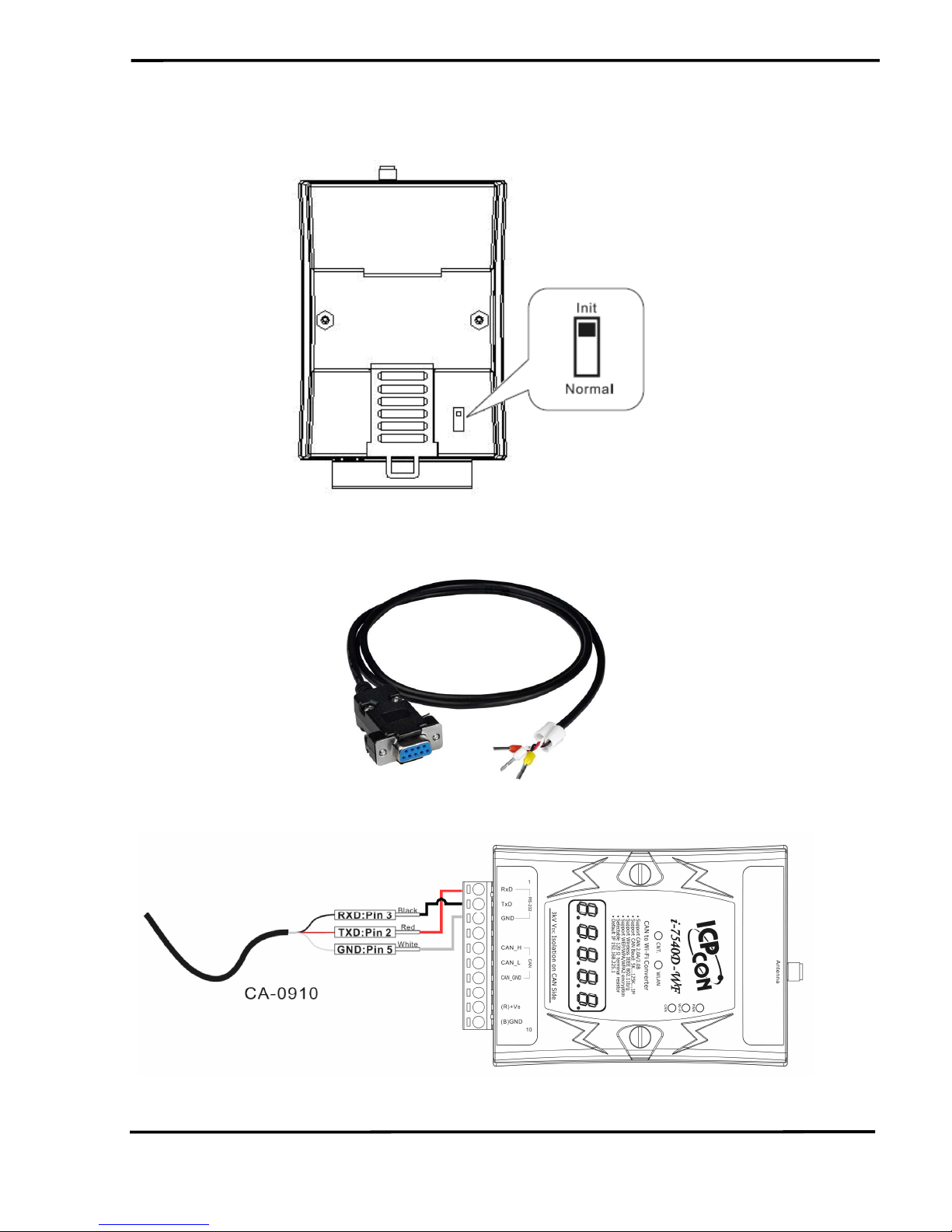
I-7540D-WF CAN to Wi-Fi Converter User’s Manual (Ver. 2.0, Jan/2012) ------------- 13
firmware of the I-7540D-WF module from computer’s RS-232 port via CA0910 cable shown as Figure 2-12.
Figure 2-10: Init Position of Dip-Switch
Figure 2-11: CA-0910 Cable
Figure 2-12: Firmware downloads connection
I-7540D-WF CAN to Wi-Fi Converter User’s Manual (Ver. 2.0, Jan/2012) ------------- 14
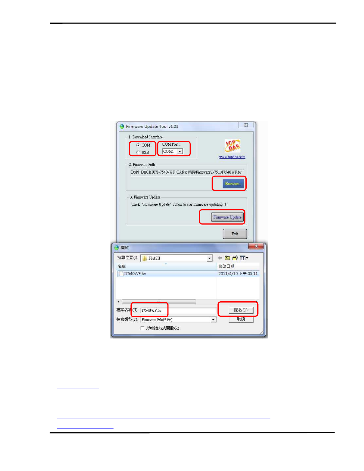
Users just need to execute “Firmware_Update_Tool.exe” and follow
the below steps to complete the firmware updating process.
[1] Choose “COM” interface and “COM Port”.
[2] Click “Browser” button to choose firmware file. (e.g. I-7540D-WF.fw)
[3] Click “Firmware Update” button to start firmware updating process.
The result will be shown in “Firmware Update” field.
Figure 2-13: I-7540D-WF firmware update process
The I-7540D-WF firmware can be downloaded from
ftp://ftp.icpdas.com/pub/cd/fieldbus_cd/can/converter/i-7540d-
wf/firmware/
The Firmware_Update_Tool program can be downloaded from
ftp://ftp.icpdas.com/pub/cd/fieldbus_cd/can/converter/i-7540dwf/software/tool/
1 2
3
4
6
5
 Loading...