

Copyright © 2020 ICP DAS Co., Ltd. All Rights Reserved. E-mail: service@icpdas.com
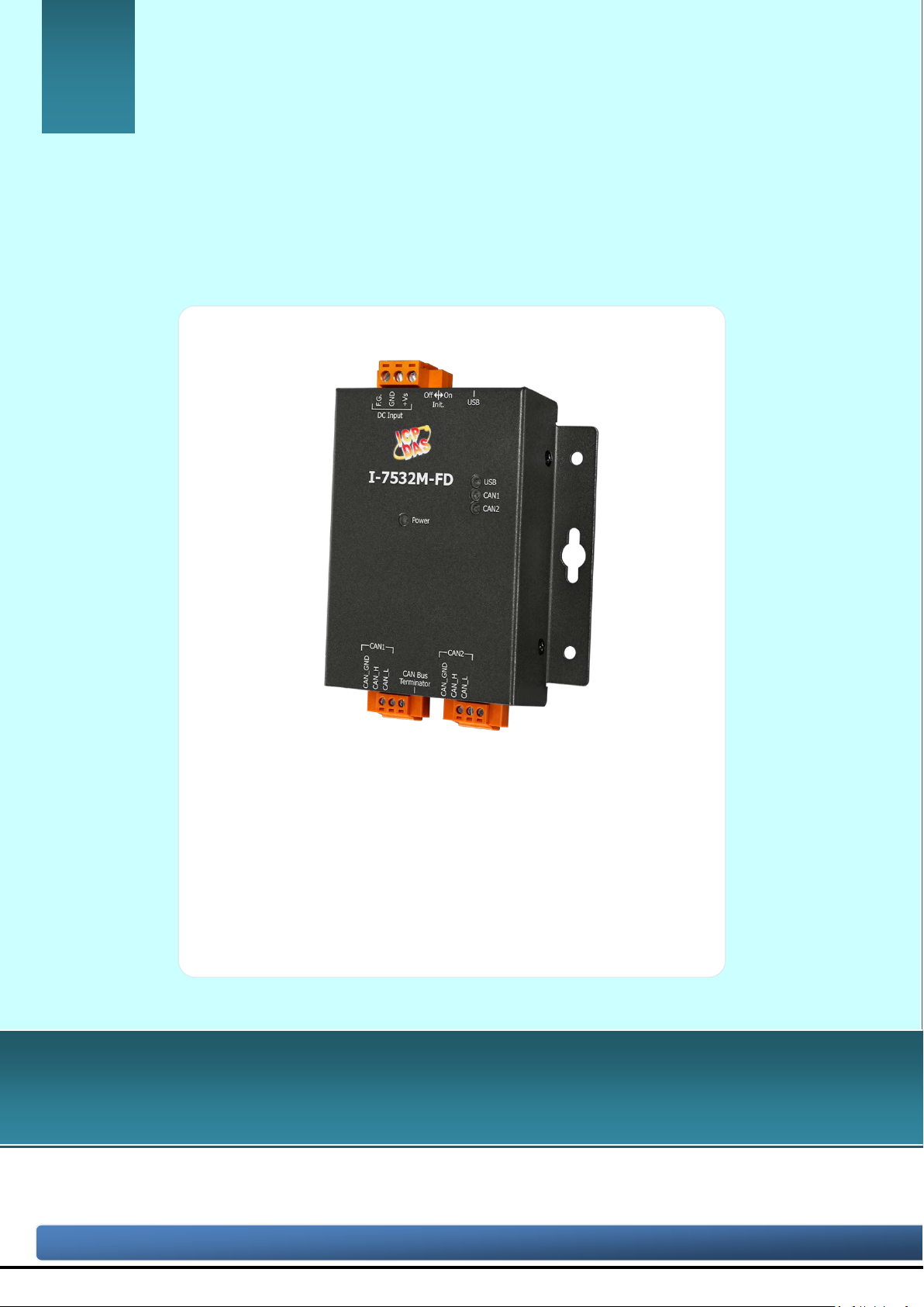
I-7532M-FD
User Manual
Version 1.2.0, April. 2021
Service and usage i nformation for
I-7532M-FD
I-7532M-FD ( 2-port CAN/CAN FD Bridge ) User Manual (version 1.2.0) Page: 1

Copyright © 2020 ICP DAS Co., Ltd. All Rights Reserved. E-mail: service@icpdas.com
Warranty
All products manufactured by ICP DAS are under warranty regarding defective
materials for a period of one year, beginning from the date of delivery to the
original purchaser.
Warning
ICP DAS assumes no liability for any damage resulting from the use of this
product.ICP DAS reserves the right to change this manual at any time without
notice. The information furnished by ICP DAS is believed to be accurate and
reliable. Howev er, no r es ponsi bili ty is ass umed by ICP D AS for its us e, not for any
infringements of patents or other rights of third parties resulting from its use.
Copyright
Copyright @ 2020 by ICP DAS Co., Ltd. All rights are reserved.
Trademark
The names used for identification only may be registered trademarks of their
respective companies.
Contact us
If you have any problem, please feel free to contact us.
You can count on us for quick response.
Email: service@icpdas.com
I-7532M-FD ( 2-port CAN/CAN FD Bridge ) User Manual (version 1.2.0) Page: 2

Copyright © 2020 ICP DAS Co., Ltd. All Rights Reserved. E-mail: service@icpdas.com
Table of Contents
1. Introduction ....................................................................................................... 5
1.1. Specifications ............................................................................................... 7
1.2. Features ........................................................................................................ 8
2. Technical data .................................................................................................... 9
2.1. Appearance .................................................................................................. 9
2.2. Pin Assignment .......................................................................................... 10
2.3. LED Indicator ........................................................................................... 11
2.4. Ter minal Resistor Setup ........................................................................... 12
2.5. Wire Connection ....................................................................................... 14
2.6. Driving Capability .................................................................................... 15
3. Software Utility ................................................................................................ 16
3.1. Install the I-7532-FD Utility .................................................................... 16
3.2. Setting up the I-7532M-FD ...................................................................... 19
3.3. Start to use I-7532-FD Utility tool ........................................................... 20
3.3.1. Get Device Configuration .................................................................. 22
3.3.2. CAN Bus Configuration ..................................................................... 23
3.3.2.1. Forwarding Rule Examples .......................................................... 26
3.3.3. CAN Filter Configuration .................................................................. 28
3.3.4. CAN Mapping Rule Configuration .................................................. 30
3.3.4.1. Mapping Rule Examples ............................................................... 33
3.3.5. CAN Merging Rule Configuration ................................................... 35
3.3.5.1. Merging Rule Examples ................................................................ 37
3.3.6. CAN Splitting Rule Configuration ................................................... 39
3.3.6.1. Splitting Rule Examples ................................................................ 41
3.3.7. CAN Status Information .................................................................... 43
4. Firmware Upgrade ........................................................................................... 44
5. Appendix ........................................................................................................... 48
5.1. Revision History ........................................................................................ 48
5.2. Dimension .................................................................................................. 49
I-7532M-FD ( 2-port CAN/CAN FD Bridge ) User Manual (version 1.2.0) Page: 3

Copyright © 2020 ICP DAS Co., Ltd. All Rights Reserved. E-mail: service@icpdas.com
5.3. Valid Data Phase Bit Rate ........................................................................ 50
I-7532M-FD ( 2-port CAN/CAN FD Bridge ) User Manual (version 1.2.0) Page: 4
Copyright © 2020 ICP DAS Co., Ltd. All Rights Reserved. E-mail: service@icpdas.com
1. Introduction
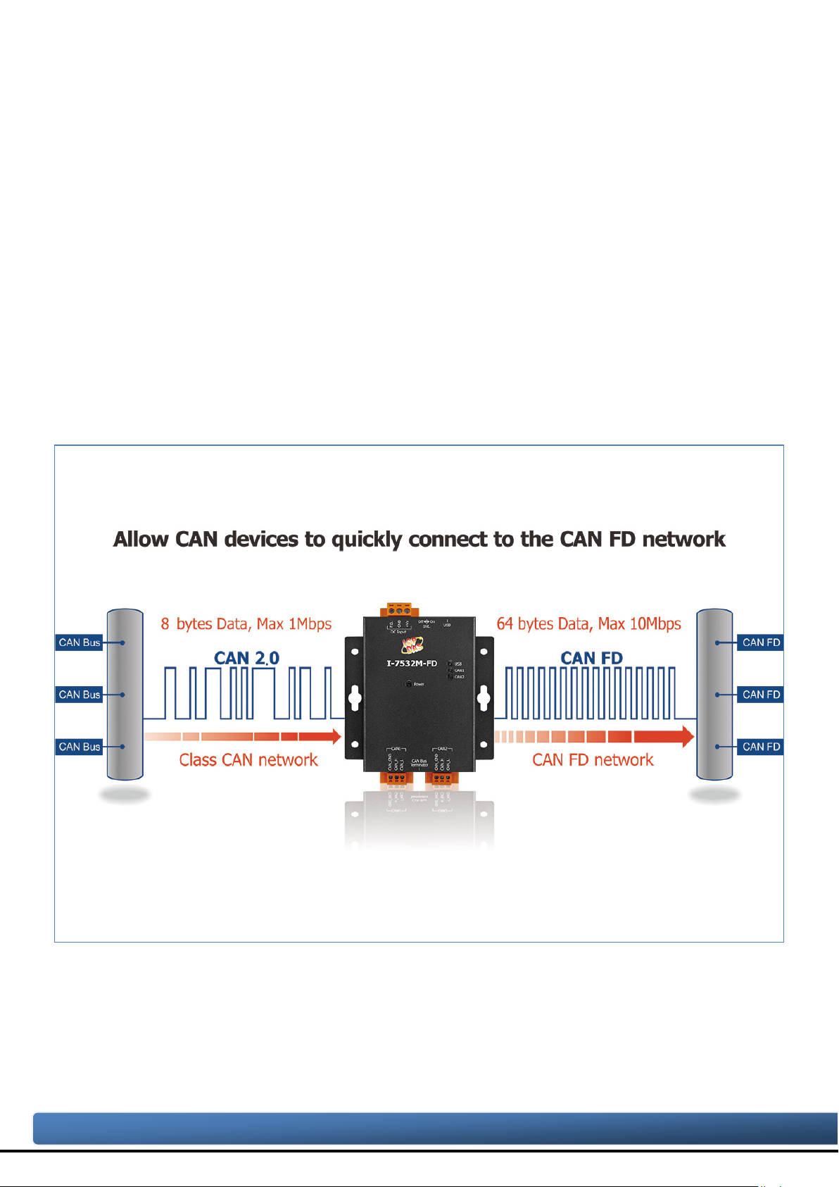
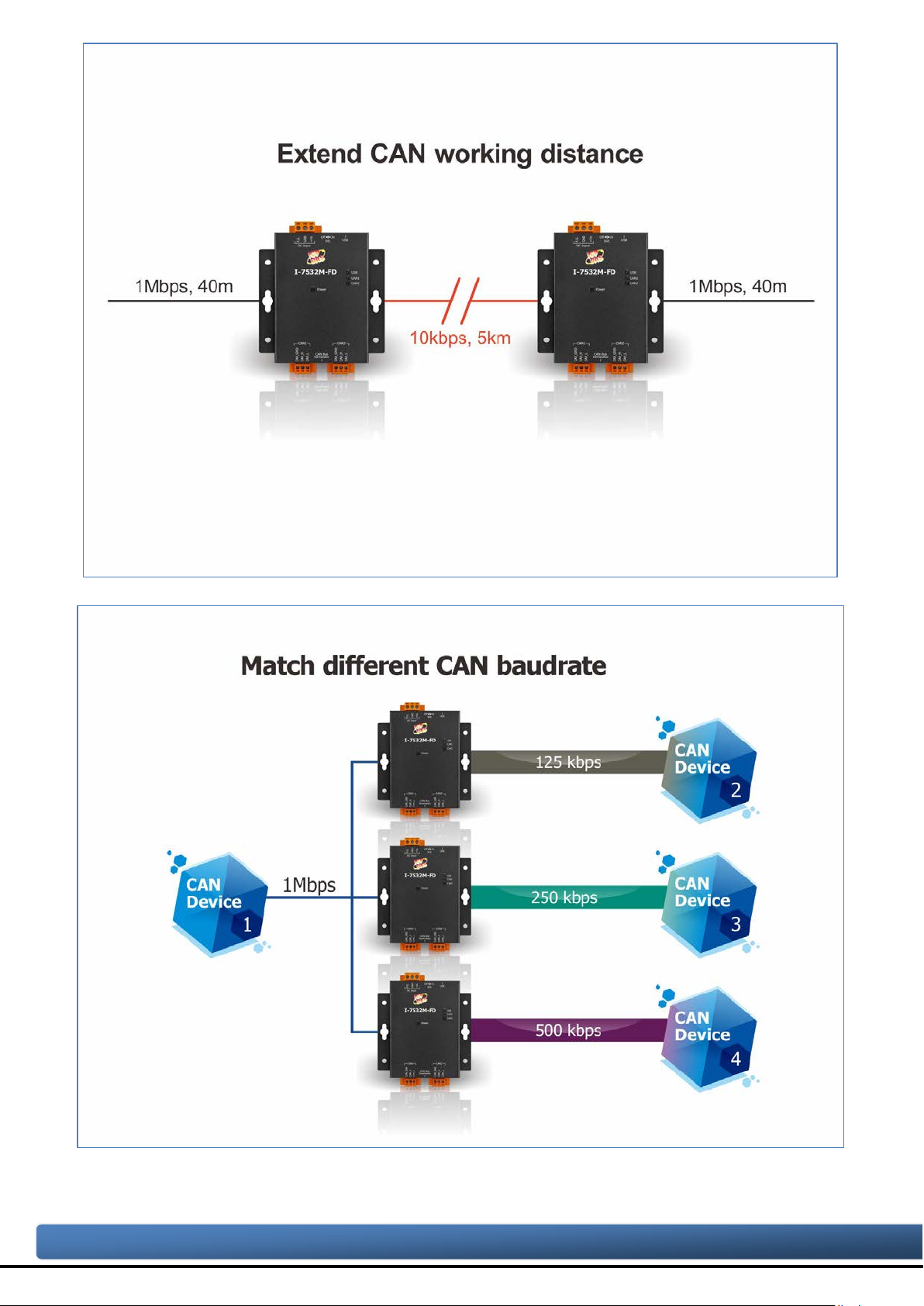
I-7532M-FD is a local CAN/ CAN FD (CAN with Flexible Data-Rate) bridge used to
establish a connection between two CAN/CAN FD networks. It can increase the bus
loading capacity, extend communication distance, connect CAN/CAN FD networks with
different baud rate and support messages transform between CAN and CAN FD
networks.
I-7532M-FD supports messages transform from CAN to CAN, CAN to CAN FD,
CAN FD to CAN and CAN FD to CAN FD. Besides, It al so supports frame m apping rule,
merging rule(combine multiple CAN messages to one CAN FD message) and splitting
rule (split one CAN FD message to multiple CAN messages) for some specific
messages transformation. Users can freedom to use these rules for their application.
After connecting USB port with PC, user can use I-7532-FD Utility tool to configure
module’s baud rate and rules. Then user can simple and easy to use the m odule.
I-7532M-FD ( 2-port CAN/CAN FD Bridge ) User Manual (version 1.2.0) Page: 5
Copyright © 2020 ICP DAS Co., Ltd. All Rights Reserved. E-mail: service@icpdas.com
I-7532M-FD ( 2-port CAN/CAN FD Bridge ) User Manual (version 1.2.0) Page: 6
Copyright © 2020 ICP DAS Co., Ltd. All Rights Reserved. E-mail: service@icpdas.com
1.1. Specifications
Model Name
I-7532M-FD
CAN Interface
Transceiver TI TCAN1042HG
Channel Number 2
Connector 3-pin terminal-block connector x 2
Trans miss i on Spe ed
CAN FD bit rates for data field: 100 ~ 10000 kbps
Terminal Resistor DIP switch for the 120 Ω terminal resistor
Isolation 3000 VDC for DC-to-DC, 2500 Vrms for photocoupler
Specification ISO 11898-2, CAN 2.0 A/B and FD
Max Data Flow 10,000 FPS for Tx/Rx (each port)
Receive Buffer 128 data frames
USB Interface
Connector 1 x USB (Mini-B)
Compatibility USB 2.0 High Speed (480Mbps)
Software Driver Built-in Windows 7/8.1/10
LED
Round LED Power, USB, CAN1, CAN2 LEDs
CAN bit rates: 10 ~ 1000 kbps,
Power
Power supply Unregulated +10 ~ +30 VDC
Protection Power reverse polarity protection, Over-voltage brown-out protection
Power Consumption 0.05A @ 24VDC
Mechanism
Installation Wall Mount or DIN-Rail
Dimensions 102 mm x 120 mm x 36.0 mm (W x L x H)
Environment
Operating Temp.
Storage Temp.
Humidity 10 ~ 90% RH, non-condensing
I-7532M-FD ( 2-port CAN/CAN FD Bridge ) User Manual (version 1.2.0) Page: 7
-25 ~ 75 ℃
-30 ~ 80 ℃

Copyright © 2020 ICP DAS Co., Ltd. All Rights Reserved. E-mail: service@icpdas.com
1.2. Features
Compatible with the ISO 11898-2 standard.
Compatible with CAN specification 2.0 A/B and FD.
CAN FD support for ISO and Non-ISO (Bosch) standards switchable.
CAN FD bit rates for data field from 100 kbps to 10000 kbps
CAN bit rates from 10 kbps to 1000 kbps.
Support CAN Bus message filter configuration. White-list filtering method and
each port supports 128 groups of standard IDs and 64 groups of extended IDs.
Support CAN/CAN FD frame forwarding rules, including basic forwarding rule,
mapping rule, merging rule and splitting rule. W hen receiving a frame on one
CAN port, this frame is processed via these rules and then send out to another
port. The process priority level of these rules are “merging rule” = “splitting rule”
> “mapping rule” > “basic forwarding rule”.
Support CAN network status analysis via Utility tool.
Messaging traffic of each port up to 10,000 fps.
The baud rate of each port can be different for highly flexibility.
Built-in switchable 120 ohm terminal resistor for CAN network.
I-7532M-FD ( 2-port CAN/CAN FD Bridge ) User Manual (version 1.2.0) Page: 8
Copyright © 2020 ICP DAS Co., Ltd. All Rights Reserved. E-mail: service@icpdas.com
2. Technical data
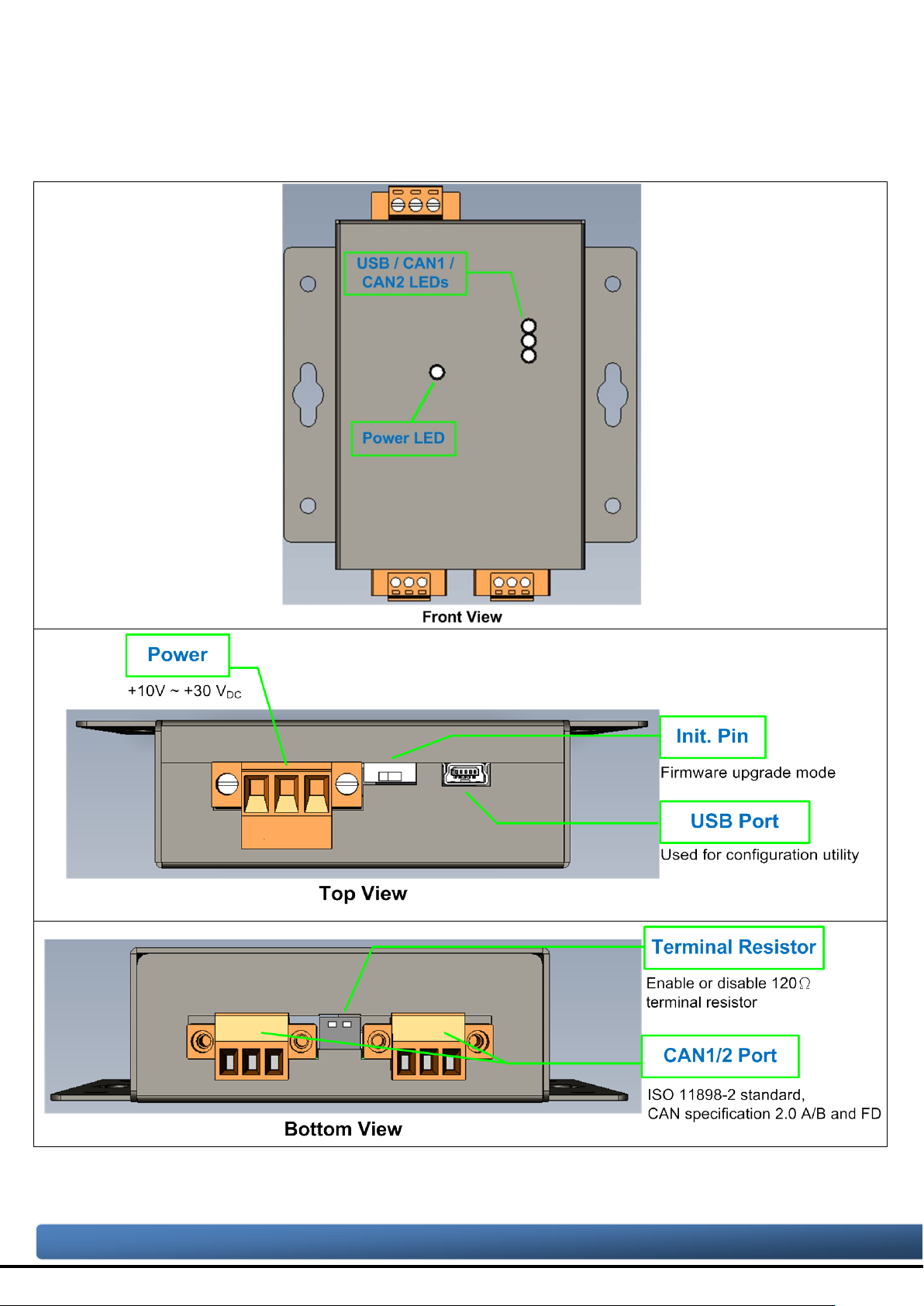
2.1. Appearance
Figure 2-1-1 Appearance of I-7532M-FD
I-7532M-FD ( 2-port CAN/CAN FD Bridge ) User Manual (version 1.2.0) Page: 9

Copyright © 2020 ICP DAS Co., Ltd. All Rights Reserved. E-mail: service@icpdas.com
2.2. Pin Assignment
The pin assignments of CAN port and power connector of I-7532M-FD is shown in
the following tables.
Table 2-2-1 Pin Assignment
Port Schematic diagram Pin Description
1. CAN_GND CAN ground of CAN port
CAN
2. CAN_H CAN_High bus line of CAN port.
3. CAN_L CAN_Low bus line of CAN port.
V olta ge Sour ce Input.
1. +Vs
+10V
Power
2. GND Power Ground.
3. F.G. Frame Ground.
DC ~ +30VDC.
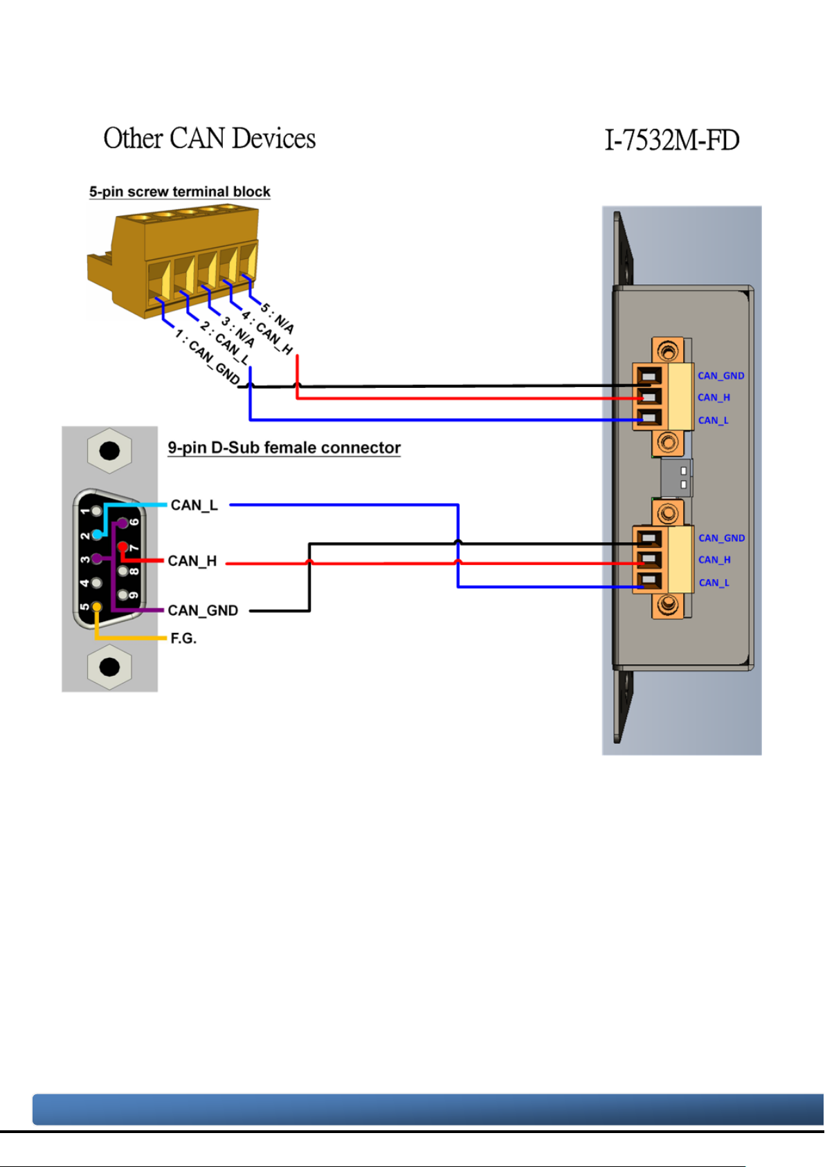
Sometimes, the CAN_GND voltage level of different CAN devices on a CAN bus
system are not equal. In this case, it could cause some problems and derogate the
system stability. There is one way to relieve this situation; users can connect the
CAN_GND of different CAN devices with each other to balance the voltage level of
CAN_GND.
Electronic circuits are always influenced by different levels of Electro-Static
Discharge (ESD), which become worse in a continental climate area. F.G. provides a
path for conducting the ESD to the earth ground. Therefore, connecting the F.G
correctly can enhance the capability of the ESD protection and improve the module’s
reliability.
Wiring of CAN_GND and F. G. is not necessary; users can modify the configuration
of wiring according to real applications.
I-7532M-FD ( 2-port CAN/CAN FD Bridge ) User Manual (version 1.2.0) Page: 10
Copyright © 2020 ICP DAS Co., Ltd. All Rights Reserved. E-mail: service@icpdas.com
2.3. LED Indicator
LED Name
Status
Description
Power
Red On
When power on the I-7532M-FD, this LED is turned on.
Red On
CAN1 Bus Off
Green On
CAN1 Idle.
Red On
CAN2 Bus Off
Green On
CAN2 Idle.
There are 4 LEDs on the I-7532M-FD. One for power indication, one for usb
indication and two for CAN bus indication. The LED assignment and description are
shown as follows.
Table 2-3-1 LED Descript ion
Green On
USB cable connected
USB
Green Flash
Communicating with Utility via USB
Red Flash CAN1 Error warning or error passive
CAN1
Green Flash Transmitting or receiving CAN messages on CAN1 port
Red Flash CAN2 Error warning or error passive
CAN2
Green Flash Transmitting or receiving CAN messages on CAN2 port
NOTE:
In “Firmware Upgrade Mode”, the USB, CAN1 and CAN2 will polling to flash red/green
led per 200 ms.
I-7532M-FD ( 2-port CAN/CAN FD Bridge ) User Manual (version 1.2.0) Page: 11
Copyright © 2020 ICP DAS Co., Ltd. All Rights Reserved. E-mail: service@icpdas.com
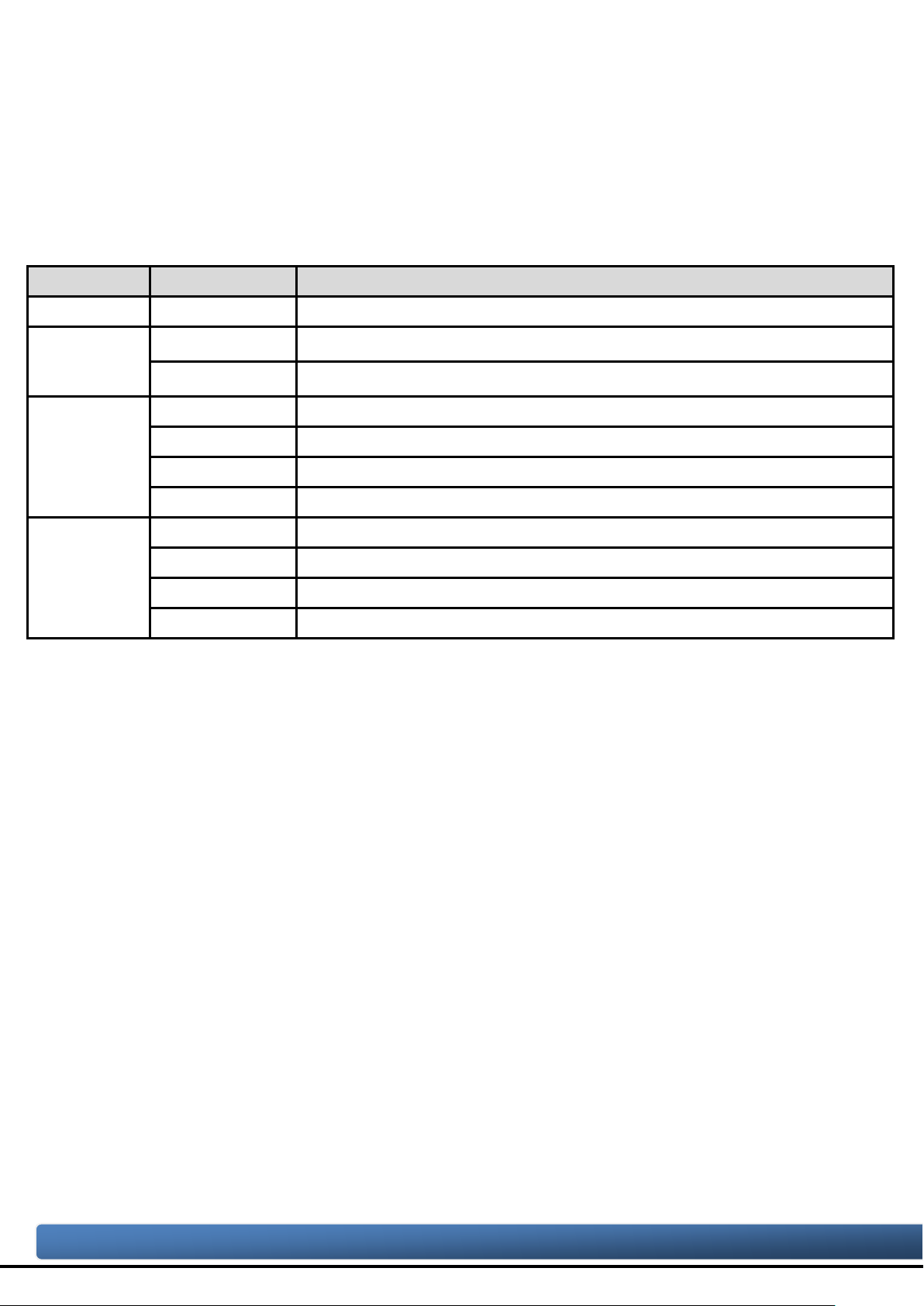
2.4. Terminal Resistor Setup
In order to minimize the reflection effects on the CAN bu s line, the CAN bus lin e has
to be terminated at both ends by two terminal resistors as in the following figure.
According to the ISO 11898-2 spec, each terminal resistor is 120Ω (or between
108Ω~132Ω). The bus topology and the positions of these terminal resistors are shown
as following figure.
Figure 2-4-1 CAN bus network topology
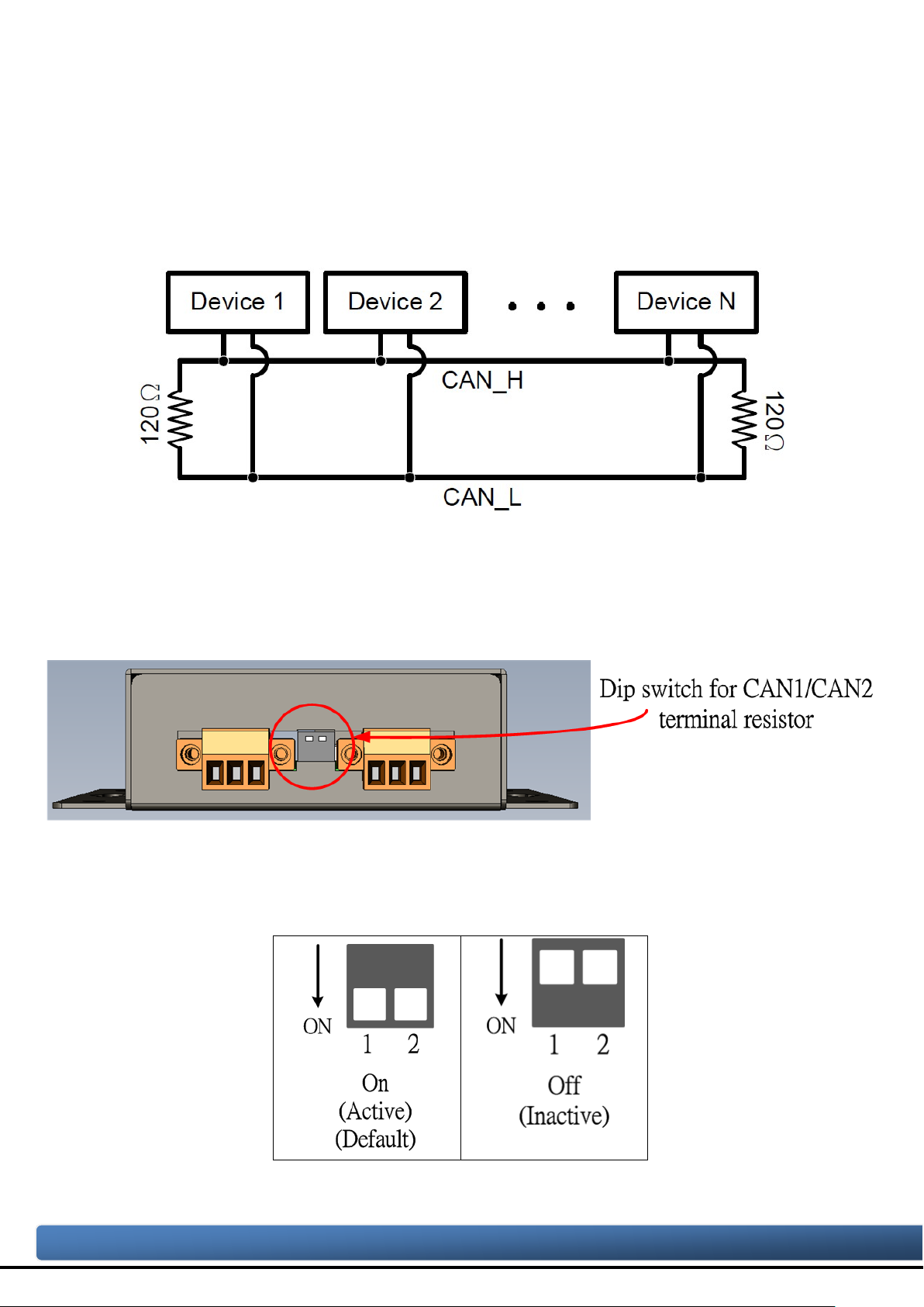
Each I-7532M-FD includes two build-in 120Ω terminal resistor, users can decider to
enabl it or not. The DIP switch for terminal resistor is on the upper of the CAN
connector.
Figure 2-4-2 Location of Terminal resistor DIP Switch
The following DIP switch statuses present the condition if the terminal resistor is
active (default) or inactive.
Figure 2-4-3 Adjustment of Terminal Resistance
I-7532M-FD ( 2-port CAN/CAN FD Bridge ) User Manual (version 1.2.0) Page: 12
Copyright © 2020 ICP DAS Co., Ltd. All Rights Reserved. E-mail: service@icpdas.com
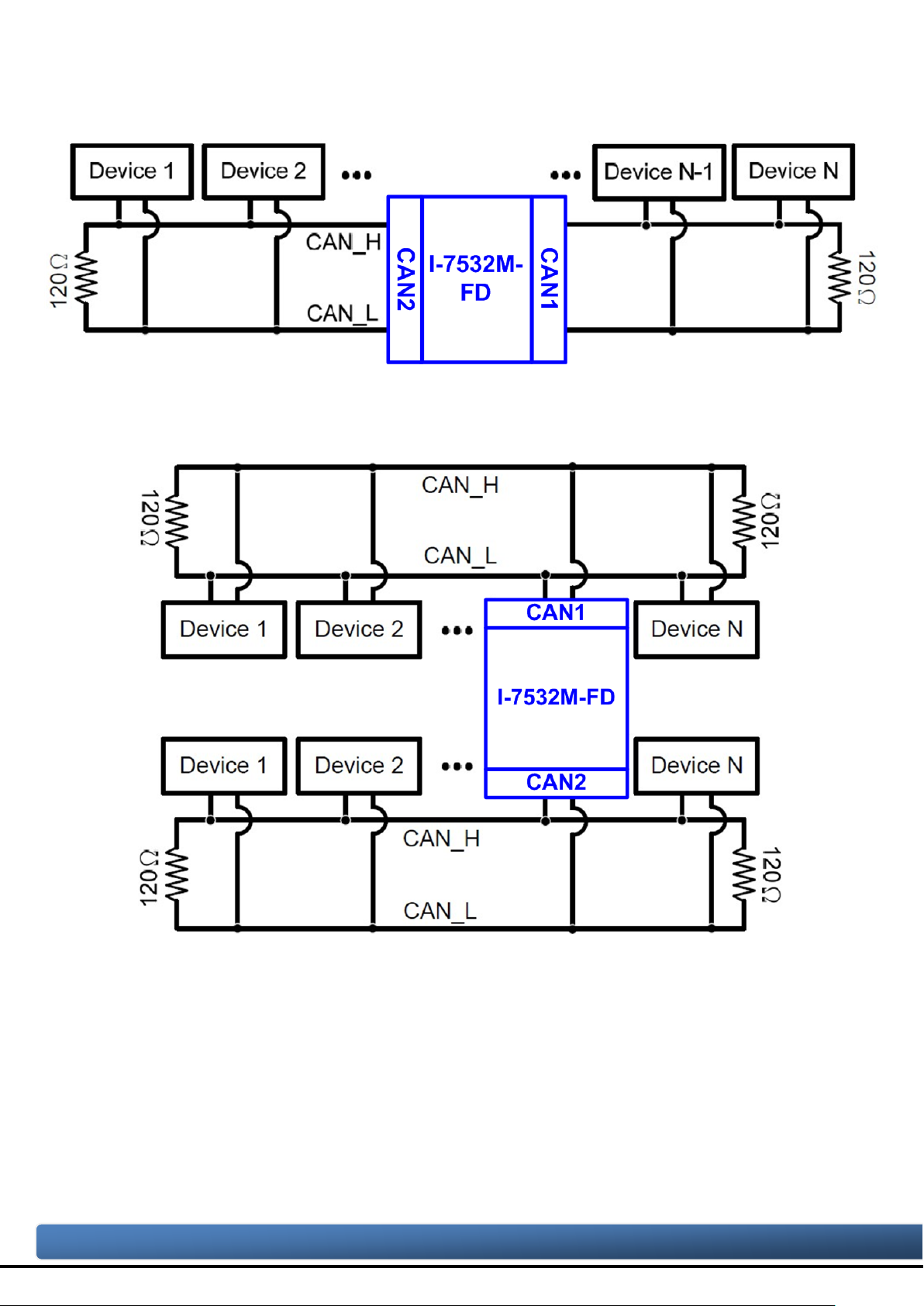
Generally, if your application is as follows, we recommend you to enable the
terminal resistor.
Figure 2-4-4 Application 1
If your application is like the structure as follows, the terminal resistor is not needed .
Figure 2-4-5 Application 2
I-7532M-FD ( 2-port CAN/CAN FD Bridge ) User Manual (version 1.2.0) Page: 13
Copyright © 2020 ICP DAS Co., Ltd. All Rights Reserved. E-mail: service@icpdas.com
2.5. Wire Connection
The wire connection of the I-7532M-FD is displayed below.
Figure 2-5-1 Wire Connection for I-7532M-FD
I-7532M-FD ( 2-port CAN/CAN FD Bridge ) User Manual (version 1.2.0) Page: 14

Copyright © 2020 ICP DAS Co., Ltd. All Rights Reserved. E-mail: service@icpdas.com
2.6. Driving Capability
Wire Cross-Section [mm2]
Resistance [Ω/km]
~0.25 (AWG23)
< 90
~0.5 (AWG20)
< 50
~1.3 (AWG16)
< 20
specific node number in t his segment
16 Nodes
32 Nodes
64 Nodes
100 Nodes
~0.25 (AWG23)
< 220
< 200
< 170
< 150
~0.8 (AWG18)
< 590
< 550
< 470
< 410
~1.3 (AWG16)
< 980
< 900
< 780
< 670
Before introducing the driving capability of the I-7532M-FD, some characteristics of
copper cable must be assumed. The AC parameters are 120Ω impedance and 5ms/,
line delay, and the DC parameter follows the table show below.
Table 2-6-1 Recommended DC parameter for CAN Bus Line
~0.8 (AWG18) < 33
Under the condition described above, users can refer to the following table to know
the maximum node number in each segment following ISO 11898-2 and the maximum
segment length when using different type of wire.
Table 2-6-2 Driving Capability
The maximum segment length [m ] under the case of
Wire Cross-Section
2
[mm
]
~0.5 (AWG20) < 390 < 360 < 310 < 270
I-7532M-FD ( 2-port CAN/CAN FD Bridge ) User Manual (version 1.2.0) Page: 15
Copyright © 2020 ICP DAS Co., Ltd. All Rights Reserved. E-mail: service@icpdas.com
3. Software Utility
When users want to use user-defined CAN/CAN FD baud rate, CAN/CAN FD
message filter and CAN mapping, merging, splitting rule function on the I-7532M-FD,
the I-7532M-FD Utility tool may be needed.
3.1. Install the I-7532-FD Utility
Step 1: Get the I-7532-FD Utility
The software is located at:
http://www.icpdas.com/en/download/show.php?num=3019&model=I-7532M-FD
Step 2: Install .NET Framework 3.5 component
The I-7532-FD Utility tool requires the .NET Framework 3.5 components. After
executing the “Setup.msi” file, it will start to install .NET Framework 3.5
components.
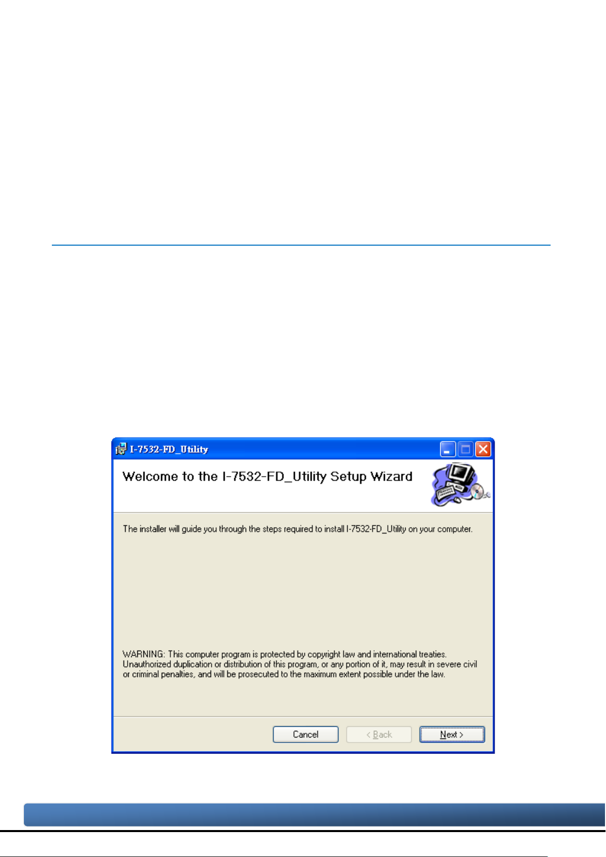
Step 3: Install Utility tool
After installing the .Net Framework components, the software will continue to install
the Utility tool.
1. Click the “Next” button to continue.
I-7532M-FD ( 2-port CAN/CAN FD Bridge ) User Manual (version 1.2.0) Page: 16

Copyright © 2020 ICP DAS Co., Ltd. All Rights Reserved. E-mail: service@icpdas.com
2. Select the installation path of the I-7532-FD Utility and click the “Next” button.
3. Confirm the installation. Click the “Next” button to start the installation
I-7532M-FD ( 2-port CAN/CAN FD Bridge ) User Manual (version 1.2.0) Page: 17

Copyright © 2020 ICP DAS Co., Ltd. All Rights Reserved. E-mail: service@icpdas.com
4. Installation complete. Click the “Close” button to exit
I-7532M-FD ( 2-port CAN/CAN FD Bridge ) User Manual (version 1.2.0) Page: 18

Copyright © 2020 ICP DAS Co., Ltd. All Rights Reserved. E-mail: service@icpdas.com
3.2. Setting up the I-7532M-FD
After installing the utility tool, please follow the following steps to set up the
communication between the Utility and the I-7532M-FD. Here is the example for the
I-7532M-FD configuration.
Step 1: Connect the PC available USB port with the USB port of the I-7532M-FD. Users
can find the communication cable (CA-USB10) in the product box.
Step 2: Power On the module and execute the I-7532-FD Utility tool.
I-7532M-FD ( 2-port CAN/CAN FD Bridge ) User Manual (version 1.2.0) Page: 19

Copyright © 2020 ICP DAS Co., Ltd. All Rights Reserved. E-mail: service@icpdas.com
3.3. Start to use I-7532-FD Utility tool
Figure 3-3-1 Main frame of the I-7532M-FD Utility tool
[Basic]
This field is used to connect to the module and get device information, get device
configuration, configure device, load device configuration from file and save device
configuration to file.
[CAN]
This field is used to configure the CAN controller mode, CAN FD specification,
arbitration/data-phase baudrate and advanced forwarding rule.
[Filter]
This field is used to configure CAN ID filter function. Users can reject remote
standard/extended CAN ID and set acceptance standard/extended CAN ID.
I-7532M-FD ( 2-port CAN/CAN FD Bridge ) User Manual (version 1.2.0) Page: 20

Copyright © 2020 ICP DAS Co., Ltd. All Rights Reserved. E-mail: service@icpdas.com
[Mapping Rule]
This field is used to configure mapping rules of the device. Mapping rule is used to
modify the received CAN/CAN FD frame format (including type, format, ID, data length,
bit rate switch and data ) from one port and then transfer i t to another port. It is useful for
user to change the received CAN/CAN FD format to another one. Each device
maximum supports 32 mapping rules.
[Merging Rule]
This field is used to configure merging rules of the device. Merging rule is used to
combine multiple CAN frames (Max. 8) to one CAN FD frame. It is useful for user to
combine multiple CAN frames datas into one CAN FD frame. Each device maximum
supports 32 merging rules.
[Splitting Rule]
This field is used to configure splitting rules of the device. Splitting rule is used to split
one CAN FD frame to multiple CAN frames (Max. 8). It is useful for use r to split datas i n
one CAN FD frame to multiple CAN frames. Each device maximum supports 32 splitting
rules.
[Status]
This fi eld is used t o check the CAN status of t he device. T his field is useful f or user to
check and analysis the device CAN network status (including no error, CAN bus off,
error passive, error warning status and transmit/receive error counter information) .
I-7532M-FD ( 2-port CAN/CAN FD Bridge ) User Manual (version 1.2.0) Page: 21

Copyright © 2020 ICP DAS Co., Ltd. All Rights Reserved. E-mail: service@icpdas.com
3.3.1. Get Device Configuration
Press the “Refresh” button to scan and list all the necessary I-7532M-FD modules
on “Module Name” location.
Then select the necessary I-7532M-FD module and press “Get Device Config.”
button to start to connect and get device configuration.
[Get Device Config.]
This button is used to get all configuration from module. After get the module’s
configuration, all the module’s parameters will be listed in “CAN”, “Filter”, “Mapping
Rule”, “Merging Rule” and “Splitting Rule” fields.
[Config. Device]
This button is used to set all the settings, listed in “CAN”, “Filter”, “Mapping Rule”,
“Merging Rule” and “Splitting Rule” fields, to module.
[Load Config. From File]
This button is used to get all configuration from a selected file. After load the module’s
configuration from a file, all the module’s parameters will be listed in “CAN”, “Filter”,
“Mapping Rule”, “Merging Rule” and “Splitting Rule” fields.
[Save Config. To File]
This button is used to save all the parameter settings, listed in “CAN”, “Filter”, “Mapping
Rule”, “Merging Rule” and “Splitting Rule” fields, to a selected file.
I-7532M-FD ( 2-port CAN/CAN FD Bridge ) User Manual (version 1.2.0) Page: 22

Copyright © 2020 ICP DAS Co., Ltd. All Rights Reserved. E-mail: service@icpdas.com
3.3.2. CAN Bus Configur ation
This field is used to configure the CAN controller mode, CAN FD specification,
arbitration/data-phase baudrate and advanced forwarding rule.
[CAN Controller]
Set the CAN port into CAN or CAN FD mode. Wh en setting the CAN port into CAN FD
mode, the CAN port can process CAN/CA N FD frames, otherwise this port just can
process CAN frame.
[CAN FD Spec.]
Set the CAN FD frame of the CAN port follows ISO or Non-ISO specification. For “ISO”
specification setting, the module uses the CAN FD frame format as specified by the
ISO11898-1. For “Non-ISO” specification setting, the module uses the CAN FD frame
format as specified by Bosch CAN FD Specification V1.0.
I-7532M-FD ( 2-port CAN/CAN FD Bridge ) User Manual (version 1.2.0) Page: 23

Copyright © 2020 ICP DAS Co., Ltd. All Rights Reserved. E-mail: service@icpdas.com
[Arbitration bit rate]
Controller
Controller
CAN
CAN FD
CAN
CAN FD
CAN
CAN FD
User can set
Default
No errect
No errect
CAN FD
CAN FD
Default
User can set
User can set
Default
CAN/CAN FD arbitration phase bit rate. Valid range: 10 kbps ~ 1000 kbps.
[Data phase bit rate]
CAN FD data phase bit rate. Valid range: 100 kbps ~ 10000 kbps
[SP]
CAN/CAN FD arbitration/data phase bit rate sample point.
Suggested range: 75.00 ~ 87.50 %
[Forwarding Rule Advanced settings]
Dependent on CAN controller setting, the forwarding rule may be diffenent. The
following table list the default forwarding rule setting. User can change the default
forwarding rule on “Advanced setting” frame.
Rx CAN
Tx CAN
Rx CAN
Rx CAN
Rx CAN FD
Rx CAN FD
CAN CAN Default No errect No errect No errect
CAN FD CAN Default No errect Default No errect
Advanced setting:
Can set “Rx CAN => CAN”, “Rx CAN FD => CAN”, “Rx CAN => CAN FD” and “Rx
CAN FD => CAN FD”.
When setting “Rx CAN => CAN” or “Rx CAN FD => CAN FD”, CAN or CAN FD
I-7532M-FD ( 2-port CAN/CAN FD Bridge ) User Manual (version 1.2.0) Page: 24

Copyright © 2020 ICP DAS Co., Ltd. All Rights Reserved. E-mail: service@icpdas.com
frame will be no changed when sent out to another port.
When setting “Rx CAN FD => CAN”, CAN FD frame with large than 8 bytes datas
will be cut off and only keep 8 bytes datas.
When setting “Rx CAN => CAN FD”:
When no checking “Stuff” item, data field of received CAN frame be no changed
and transform to CAN FD frame.
When checking “Stuff” item, received CAN frame (data length equal to 8) will be
transformed and stuffed with “stuff byte” value ; received CAN frame (data
length: 0 ~ 8) will be no changed and transform to CAN FD frame.
Can set CAN FD frame with “BRS” (bit rate switch) or not.
I-7532M-FD ( 2-port CAN/CAN FD Bridge ) User Manual (version 1.2.0) Page: 25

Copyright © 2020 ICP DAS Co., Ltd. All Rights Reserved. E-mail: service@icpdas.com
3.3.2.1. For warding Rule Ex amples
1. “Rx CAN => CAN”
Set CAN1 “Rx CAN => CAN”. Received CAN frame on port 1 will be no change and
transfer to port 2.
Frame on CAN network (port 1)
port Driection CAN type ID Frame type Frame format Datalen Data
1 Rx CAN 0x111 standard data 8 00-11-22-33-44-55-66-77
Frame on CAN network (port 2)
port Driection CAN type ID Frame type Frame format Datalen Data
2 Tx CAN 0x111 standard data 8 00-11-22-33-44-55-66-77
2. “Rx CAN FD => CAN”
Set CAN1 “Rx CAN FD => CAN”. CAN FD with data length large than 8 will be cut
off and only keep 8 bytes datas
Frame on CAN network (port 1)
port Driection CAN type ID Frame type Frame format Datalen Data
1 Rx CAN FD 0x111 standard data 64
Frame on CAN network (port 2)
port Driection CAN type ID Frame type Frame format Datalen Data
2 Tx CAN 0x111 standard data 8 00-11-22-33-44-55-66-77
00-11-22-33-44-55-66-77
00-00-00-00-00 …
I-7532M-FD ( 2-port CAN/CAN FD Bridge ) User Manual (version 1.2.0) Page: 26

Copyright © 2020 ICP DAS Co., Ltd. All Rights Reserved. E-mail: service@icpdas.com
3. “Rx CAN => CAN FD”
Set CAN2 “Rx CAN => CAN FD”. When receiving a CAN frame with data length
equal to 8, this frame will be transformed to a CAN FD frame with data length 16,
stuff with 0xFF and enable BRS.
Frame on CAN network (port 2)
port Driection CAN type ID Frame type Frame format Datalen Data
2 Rx CAN 0x111 standard data 8 00-11-22-33-44-55-66-77
Frame on CAN network (port 1)
port Driection CAN type ID Frame type Frame format Datalen Data
1 Tx CAN FD 0x111 standard data + BRS 16
00-11-22-33-44-55-66-77-
FF-FF-FF-FF-FF-FF-FF-FF
4. “Rx CAN FD => CAN FD”
Set CAN2 “Rx CAN FD => CAN FD”. Received CAN FD frame on port 2 will be no
change and transfer to port 1.
Frame on CAN network (port 2)
port Driection CAN type ID Frame type Frame format Datalen Data
2 Rx CAN FD 0x111 standard Data+BRS 16
00-11-22-33-44-55-66-77-
88-99-AA-BB-CC-DD-EE-FF
Frame on CAN network (port 1)
port Driection CAN type ID Frame type Frame format Datalen Data
1 Tx CAN FD 0x111 standard Data+BRS 16
00-11-22-33-44-55-66-77-
88-99-AA-BB-CC-DD-EE-FF
I-7532M-FD ( 2-port CAN/CAN FD Bridge ) User Manual (version 1.2.0) Page: 27

Copyright © 2020 ICP DAS Co., Ltd. All Rights Reserved. E-mail: service@icpdas.com
3.3.3. CAN Filter Configuration
This field is used to configure CAN ID filter function. Users can reject remote
standard/extended CAN ID and set acceptance standard/extended CAN ID.
The “Reject Remote Frame ” is used to reject remote standard/extended frame. And
the “Standard ID/Extended ID” field is used to set accepted standard/extended CAN IDs
(using white-list rule). The CAN1/CAN2 filter settings wil take effect after press the
confirm button.
[Reject Remote Frame] block:
Click the “Reject Remote Standard/Extended Frame” item to select whether to reject
remote standard/extended CAN frame or not
I-7532M-FD ( 2-port CAN/CAN FD Bridge ) User Manual (version 1.2.0) Page: 28

Copyright © 2020 ICP DAS Co., Ltd. All Rights Reserved. E-mail: service@icpdas.com
[Standard ID/Extended ID] block:
Press the “Add”, “Delete” button to add/delete a range of standard/extended CAN ID
into filter frame.
I-7532M-FD ( 2-port CAN/CAN FD Bridge ) User Manual (version 1.2.0) Page: 29

Copyright © 2020 ICP DAS Co., Ltd. All Rights Reserved. E-mail: service@icpdas.com
3.3.4. CAN Mapping Rule Configuration
This field is used to configure mapping rules of the device. Mapping rule is used to
modify the received CAN/CAN FD frame format (including type, format, ID, data length,
bit rate switch and data ) from one port and then transfer i t to another port. It i s useful for
user to change the received CAN/CAN FD format to another one. Each device
maximum supports 32 mapping rules.
[Enable]
Enable or disable mapping rule function of this CAN port.
[No]
Rule number. Maximum support 32 mapping rules. The smaller the number, the higher
the process priority level.
[C_Type]
CAN or CAN FD frame type.
0: CAN frame, 1: CAN FD frame. *: no check.
[F_Type]
Standard or extended frame type
0: standard frame, 1: extended frame. *: no check.
I-7532M-FD ( 2-port CAN/CAN FD Bridge ) User Manual (version 1.2.0) Page: 30

Copyright © 2020 ICP DAS Co., Ltd. All Rights Reserved. E-mail: service@icpdas.com
[Format]
Data or remote frame format
0: data frame, 1: remote frame. *: no check.
[DL]
Data length
0~8: CAN frame data length, 0~64: CAN FD frame data length. *: no check.
[BRS]
Bit rate switch or not
0: not use bit rate switch, 1: use bit rate switch. *: no check.
[ID]
ID field of CAN/CAN FD frame
*: no check.
[Data(hex)]
Data field of CAN/CAN FD frame
*: no check.
I-7532M-FD ( 2-port CAN/CAN FD Bridge ) User Manual (version 1.2.0) Page: 31

Copyright © 2020 ICP DAS Co., Ltd. All Rights Reserved. E-mail: service@icpdas.com
After press “Add” or “Modify” button, users can set the mapping rule parameters on
“Mapping Rule Configuration” frame.
Mapping rule supports mapping frame via “CAN Type”, “Frame Type”, “Format”,
“DataLen”, “BRS”, “ID” and “Data”. User can select the necessary items via
checking the checkbox of the item. In “Source ” field, checked items will be
compared with the set value. In “Destination” f ield, checked items will be modified
with the set value.
I-7532M-FD ( 2-port CAN/CAN FD Bridge ) User Manual (version 1.2.0) Page: 32

Copyright © 2020 ICP DAS Co., Ltd. All Rights Reserved. E-mail: service@icpdas.com
3.3.4.1. Mappi ng Rule Examples
1. Not map data field of received CAN frame.
Receive CAN standard ID: 0x111 on port 1 and transform it to port 2 with CAN
standard ID: 0x222. No check and modify the data length and data field.
Frame on CAN network (port 1)
port Driection CAN type ID Frame type Frame format Datalen Data
1 Rx CAN 0x111 standard data 8 00-11-22-33-44-55-66-77
Frame on CAN network (port 2)
port Driection CAN type ID Frame type Frame format Datalen Data
2 Tx CAN 0x222 standard data 8 00-11-22-33-44-55-66-77
I-7532M-FD ( 2-port CAN/CAN FD Bridge ) User Manual (version 1.2.0) Page: 33

Copyright © 2020 ICP DAS Co., Ltd. All Rights Reserved. E-mail: service@icpdas.com
2. Map data field of received CAN frame.
Receive CAN standard ID: 0x001, DataLen: 0x3 and Data: 00-01-02 on port 1 and
transform it to port 2 with CAN FD extended ID: 0x00000002, DataLen: 0x8, Data:
00-11-22-33-44-55-66-77 and enable bit rate switch.
Frame on CAN network (port 1)
port Driection CAN type ID Frame type Frame format Datalen Data
1 Rx CAN 0x001 standard data 3 00-11-22
Frame on CAN network (port 2)
port Driection
2 Tx CAN FD 0x00000002 extended data + BRS 8 00-11-22-33-44-55-66-77
CAN
ID Frame type
type
Frame
Datalen Data
format
I-7532M-FD ( 2-port CAN/CAN FD Bridge ) User Manual (version 1.2.0) Page: 34

Copyright © 2020 ICP DAS Co., Ltd. All Rights Reserved. E-mail: service@icpdas.com
3.3.5. CAN Merging Rule Configuration
This field is used to configure merging rules of the device. Merging rule is used to
combine multiple CAN frames (Max. 8) to one CAN FD frame. It is useful for user to
combine multiple CAN frames datas into one CAN FD frame. Each device maximum
supports 32 merging rules.
The merging rule field is similar to mapping rule field. After setting the rules on “Merging
Rule Configuration” frame, rules will be display ed on the fr ame list. The smaller the “No”
number, the higher the process priority level.User can press the “Add” but ton to add a
new rule or press the “Modify” button to modify the selected rule.
I-7532M-FD ( 2-port CAN/CAN FD Bridge ) User Manual (version 1.2.0) Page: 35

Copyright © 2020 ICP DAS Co., Ltd. All Rights Reserved. E-mail: service@icpdas.com
The CAN F D frame will be sent out when receiving the latest “No” of CAN frame. All
the received CAN frames datas in the CAN list will be combined to the data field of
the CAN FD frame.
Each merging rule maximum support merging 8 CAN frames to to one CAN FD
frame, and the total data l ength of these CA N frames can not large than the CAN
FD frame “DL” value.
In the same merging rule, each CAN frames IDs are different to each other.
The “Stuff Byte” value will be stuffed into CAN FD frame data field when the sum of
all CAN frames data length is less than t h e CAN FD fra me “DL” value.
I-7532M-FD ( 2-port CAN/CAN FD Bridge ) User Manual (version 1.2.0) Page: 36

Copyright © 2020 ICP DAS Co., Ltd. All Rights Reserved. E-mail: service@icpdas.com
3.3.5.1. Merging Rule Examples
1. Merge three CAN frames to one CAN FD frame
Merge three CAN frames (ID: 0x 001, 0x 002, 0x003, DL: 8) on p ort 1 to one C AN FD
frame (ID: 0x111, DL: 24 ). After receiving the CAN frame of ID: 0x003, the
converted CAN FD frame will be send out to port 2.
Frame on CAN network (port 1)
port Driection CAN type ID Frame type Frame format Datalen Data
1 Rx CAN 0x001 standard data 8 00-01-02-03-04-05-06-07
1 Rx CAN 0x002 standard data 8 08-09-0A-0B-0C-0D-0E-0F
1 Rx CAN 0x003 standard data 8 10-11-12-13-14-15-16-17
Frame on CAN network (port 2)
port Driection CAN type ID Frame type Frame format Datalen Data
00-01-02-03-04-05-06-07-
2 Tx CAN FD 0x111 standard Data + BRS 24
08-09-0A-0B-0C-0D-0E-0F-
10-11-12-13-14-15-16-17
I-7532M-FD ( 2-port CAN/CAN FD Bridge ) User Manual (version 1.2.0) Page: 37

Copyright © 2020 ICP DAS Co., Ltd. All Rights Reserved. E-mail: service@icpdas.com
2. Merge three CAN frames to one CAN FD frame (with “Stuff Byte”)
Merge three CAN frames (ID: 0x001, 0x 002, 0x003, DL: 8) on p ort 1 to one C AN FD
frame (ID: 0x111, DL: 32 ) stuffed with “Stuff Byte” : 0xFF. After receiving the CAN
frame of ID: 0x003, the converted CAN FD frame will be send out to port 2.
Frame on CAN network (port 1)
port Driection CAN type ID Frame type Frame format Datalen Data
1 Rx CAN 0x001 standard data 8 00-01-02-03-04-05-06-07
1 Rx CAN 0x002 standard data 8 08-09-0A-0B-0C-0D-0E-0F
1 Rx CAN 0x003 standard data 8 10-11-12-13-14-15-16-17
Frame on CAN network (port 2)
port Driection CAN type ID Frame type Frame format Datalen Data
00-01-02-03-04-05-06-07-
2 Tx CAN FD 0x111 standard Data + BRS 32
08-09-0A-0B-0C-0D-0E-0F-
10-11-12-13-14-15-16-17-
FF-FF-FF-FF-FF-FF-FF-FF
I-7532M-FD ( 2-port CAN/CAN FD Bridge ) User Manual (version 1.2.0) Page: 38

Copyright © 2020 ICP DAS Co., Ltd. All Rights Reserved. E-mail: service@icpdas.com
3.3.6. CAN Splitting Rule Configuration
This field is used to configure splitting rules of the device. Splitting rule is used to
split one CAN FD frame to multipl e CAN f r a mes ( Ma x. 8 ). It is useful for user to split
datas in one CAN FD frame to multiple CAN frames. Each device maximum supports 32
splitting rules.
The splitting rule field is similar to merging rule field. After setting the rules on “Splitting
Rule Configuration” frame, rules will be display ed on the fr ame list. The smaller the “No”
number , the higher the process priority level. User can press the “Add” button to add a
new rule or press the “Modify” button to modify the selected rule.
I-7532M-FD ( 2-port CAN/CAN FD Bridge ) User Manual (version 1.2.0) Page: 39

Copyright © 2020 ICP DAS Co., Ltd. All Rights Reserved. E-mail: service@icpdas.com
Each splitting rule maximum support one CAN FD frame splitting to 8 CAN frames,
and the total data length of these CAN frames can not large than the CAN FD frame
“DL” value.
In th e same splitting rule, each CAN frames ID s are different to each other.
I-7532M-FD ( 2-port CAN/CAN FD Bridge ) User Manual (version 1.2.0) Page: 40

Copyright © 2020 ICP DAS Co., Ltd. All Rights Reserved. E-mail: service@icpdas.com
3.3.6.1. Splitting Rule Examples
1. Split one CAN FD frame to four CAN frames.
When receiving the CAN FD frame (standard ID: 0x123, DL: 32, BRS enable) on
port 1, t his frame will be splitted into four CAN frames (standard ID: 0x001, 0x002,
0x003, 0x004) with 8 bytes datas and sent out to port 2.
Frame on CAN network (port 1)
port Driection CAN type ID Frame type Frame format Datalen Data
00-01-02-03-04-05-06-07-
1 Rx CAN FD 0x123 standard Data + BRS 32
08-09-0A-0B-0C-0D-0E-0F-
10-11-12-13-14-15-16-17-
18-19-1A-1B-1C-1D-1E-1F
Frame on CAN network (port 1)
port Driection CAN type ID Frame type Frame format Datalen Data
2 Tx CAN 0x001 standard data 8 00-01-02-03-04-05-06-07
2 Tx CAN 0x002 standard data 8 08-09-0A-0B-0C-0D-0E-0F
2 Tx CAN 0x003 standard data 8 10-11-12-13-14-15-16-17
2 Tx CAN 0x004 standard data 8 18-19-1A-1B-1C-1D-1E-1F
I-7532M-FD ( 2-port CAN/CAN FD Bridge ) User Manual (version 1.2.0) Page: 41

Copyright © 2020 ICP DAS Co., Ltd. All Rights Reserved. E-mail: service@icpdas.com
2. Split one CAN FD frame to three CAN frames. (throw away four bytes data)
When receiving the CAN FD frame (standard ID: 0x123, DL: 20, BRS enable) on
port 1, this frame will be splitted into three CAN frames (standard ID: 0x001, 0x002,
0x003) with 6/6/4 bytes datas and sent out to port 2. The latest four bytes datas of
CAN FD frame will be throw away.
Frame on CAN network (port 1)
port Driection CAN type ID Frame type Frame format Datalen Data
00-01-02-03-04-05-06-07-
1 Rx CAN FD 0x123 standard Data + BRS 20
08-09-0A-0B-0C-0D-0E-0F-
10-11-12-13
Frame on CAN network (port 1)
port Driection CAN type ID Frame type Frame format Datalen Data
2 Tx CAN 0x001 standard data 6 00-01-02-03-04-05
2 Tx CAN 0x002 standard data 6 06-07-08-09-0A-0B
2 Tx CAN 0x003 standard data 4 0C-0D-0E-0F
I-7532M-FD ( 2-port CAN/CAN FD Bridge ) User Manual (version 1.2.0) Page: 42

Copyright © 2020 ICP DAS Co., Ltd. All Rights Reserved. E-mail: service@icpdas.com
3.3.7. CAN Status Information
This field is used to check the CAN status of the device. This field is useful for user
to check and analysis the device CAN network status (including no error, bus of f , error
passive, error warning status and transmit/receive error counter information) .
[Time]
The local time of the PC which running the Utility tool.
[Error status]
CAN network status of the device CAN port, including no error, CAN bus off, error
passive, error warning status.
[TxEC]
Transmit error counter of the device CAN port Current value of the transmit error
counter.
[RxEC]
Receive error counter of the device CAN port. Current value of the receive error
counter.
I-7532M-FD ( 2-port CAN/CAN FD Bridge ) User Manual (version 1.2.0) Page: 43

Copyright © 2020 ICP DAS Co., Ltd. All Rights Reserved. E-mail: service@icpdas.com
4. Firmware U pgrade
Please refer to the following steps to upgrade the firmware of I-7532M-FD module.
Step 1: Power off the I-7532M-FD.
Step 2: Set the Init. dip switch to ‘ON’ position.
Step 3: Power on the I-7532M-FD, the red and green leds of USB, CAN1 and CAN2 will
polling to flash per 200 milliseconds.
Step 4: Connect the PC available USB port with the USB port of the I-7532M-FD. Users
can find the communication cable (CA-USB10) in the product box.
Figure 4-1-1 Wire connection of the USB
Step 5: At this time, the I-7532M-FD module will be simulated as a “USB Mass
Storage Device”, and one more “USB Dis k” window, will pop up on the PC side.
Then users can upgrade the firmware of the I-7532M-FD module via this USB
disk.
Step 6: Get the “Firmware Update Tool” and firmware file.
The “Firmware Update Tool” is located at:
http://www.icpdas.com/en/download/show.php?num=3018&model=I-7532M-FD
The firmware is located at:
http://www.icpdas.com/en/download/show.php?num=3020&model=I-7532M-FD
I-7532M-FD ( 2-port CAN/CAN FD Bridge ) User Manual (version 1.2.0) Page: 44

Copyright © 2020 ICP DAS Co., Ltd. All Rights Reserved. E-mail: service@icpdas.com
Step 7: Execute the “Firmware Update Tool”.
Step 8: Select USB port and the necessary USB Disk of PC
I-7532M-FD ( 2-port CAN/CAN FD Bridge ) User Manual (version 1.2.0) Page: 45

Copyright © 2020 ICP DAS Co., Ltd. All Rights Reserved. E-mail: service@icpdas.com
Step 9: Press the the “Browser…” button and select the firmware file (*.fw).
Step 10: Press the “Firmware Update” button to update the firmware. After successfu lly
to update the firmware, the “Firmware Update Success! Please Reboot Module!”
information will be display on the “3. Firmware Update” frame.
I-7532M-FD ( 2-port CAN/CAN FD Bridge ) User Manual (version 1.2.0) Page: 46

Copyright © 2020 ICP DAS Co., Ltd. All Rights Reserved. E-mail: service@icpdas.com
Step 11: Set the Init. dip switch to the “Off” position and reboot the module.Then press
the “Exit” button to exit.
I-7532M-FD ( 2-port CAN/CAN FD Bridge ) User Manual (version 1.2.0) Page: 47

Copyright © 2020 ICP DAS Co., Ltd. All Rights Reserved. E-mail: service@icpdas.com
5. Appendix
5.1. Revision History
This chapter provides revision history information to this document.
The table below shows the revision history.
Revision Date Description
1.0.0 2020/10/05 Initial issue
1.1.0 2021/01/25
1.2.0 2021/04/12
Upgrade CAN FD data bit rate to 10000
kbps
Add appendix 5.3 for valid data phase
bit rate that module support.
I-7532M-FD ( 2-port CAN/CAN FD Bridge ) User Manual (version 1.2.0) Page: 48

Copyright © 2020 ICP DAS Co., Ltd. All Rights Reserved. E-mail: service@icpdas.com
5.2. Dimension
I-7532M-FD ( 2-port CAN/CAN FD Bridge ) User Manual (version 1.2.0) Page: 49

Copyright © 2020 ICP DAS Co., Ltd. All Rights Reserved. E-mail: service@icpdas.com
5.3. Valid Data Phase Bit Rate
Supported Data Phase Bit Rate (kbps)
Items
0 1 2 3 4
0
10000.000
8571.429
7500.000
6666.667
6000.000
10
3750.000
3529.412
3333.333
3157.895
3000.000
15
2857.143
2727.273
2608.696
2500.000
2400.000
20
2307.692
2222.222
2142.857
2068.966
2000.000
25
1935.484
1875.000
1818.182
1764.706
1714.286
30
1666.667
1621.622
1578.947
1538.462
1500.000
40
1304.348
1276.596
1250.000
1224.49
1200.000
45
1176.471
1153.846
1132.075
1111.111
1090.909
50
1071.429
1052.632
1034.483
1016.949
1000.000
55
983.6066
967.7419
952.381
937.500
923.0769
60
909.0909
895.5224
882.3529
869.5652
857.1429
70
789.4737
779.2208
769.2308
759.4937
750.000
75
740.7407
731.7073
722.8916
714.2857
705.8824
80
697.6744
689.6552
681.8182
674.1573
666.6667
85
659.3407
652.1739
645.1613
638.2979
631.5789
90
625.000
618.5567
612.2449
606.0606
600.000
100
566.0377
560.7477
555.5556
550.4587
545.4545
105
540.5405
535.7143
530.9735
526.3158
521.7391
110
517.2414
512.8205
508.4746
504.2017
500.000
115
495.8678
491.8033
487.8049
483.871
480.000
120
476.1905
472.4409
468.750
465.1163
461.5385
130
441.1765
437.9562
434.7826
431.6547
428.5714
135
425.5319
422.5352
419.5804
416.6667
413.7931
140
410.9589
408.1633
405.4054
402.6846
400.000
145
397.351
394.7368
392.1569
389.6104
387.0968
150
384.6154
382.1656
379.7468
377.3585
375.000
160
361.4458
359.2814
357.1429
355.0296
352.9412
165
350.8772
348.8372
346.8208
344.8276
342.8571
5 5454.545 5000.000 4615.385 4285.714 4000.000
35 1463.415 1428.571 1395.349 1363.636 1333.333
65 845.0704 833.3333 821.9178 810.8108 800.000
95 594.0594 588.2353 582.5243 576.9231 571.4286
125 458.0153 454.5455 451.1278 447.7612 444.4444
155 372.6708 370.3704 368.0982 365.8537 363.6364
I-7532M-FD ( 2-port CAN/CAN FD Bridge ) User Manual (version 1.2.0) Page: 50

Copyright © 2020 ICP DAS Co., Ltd. All Rights Reserved. E-mail: service@icpdas.com
170
340.9091
338.9831
337.0787
335.1955
333.3333
175
331.4917
329.6703
327.8689
326.087
324.3243
180
322.5806
320.8556
319.1489
317.4603
315.7895
185 314.1361 312.500 310.8808 309.2784 307.6923
190
306.1224
304.5685
303.0303
301.5075
300.000
195
298.5075
297.0297
295.5665
294.1176
292.6829
200
291.2621
289.8551
288.4615
287.0813
285.7143
205
284.3602
283.0189
281.6901
280.3738
279.0698
210
277.7778
276.4977
275.2294
273.9726
272.7273
220
265.4867
264.3172
263.1579
262.0087
260.8696
225
259.7403
258.6207
257.5107
256.4103
255.3191
230
254.2373
253.1646
252.1008
251.046
250.000
235
248.9627
247.9339
246.9136
245.9016
244.898
240
243.9024
242.915
241.9355
240.9639
240.000
290
202.7027
202.0202
201.3423
200.6689
200.000
295 ~ 365
…
365
161.7251
161.2903
160.8579
160.4278
160.000
370~390
…
390
151.5152
151.1335
150.7538
150.3759
150.000
470
126.0504
125.7862
125.523
125.261
125.000
475 ~ 490
…
490
120.9677
120.7243
120.4819
120.2405
120.000
495 ~ 590
…
590
100.6711
100.5025
100.3344
100.1669
100.000
215 271.4932 270.2703 269.0583 267.8571 266.6667
245 ~ 290 …
395~470 …
I-7532M-FD ( 2-port CAN/CAN FD Bridge ) User Manual (version 1.2.0) Page: 51
 Loading...