

ICPDAS I-7531, I-7531-UT User Manual

User Manual
Version 1.6.0 February 2018
I-7531(-UT)
(CAN Bus Isolated Repeater)
Written by Ives Shen
Edited by Kalia Huang

I-7531 & I-7531-UT (CAN Bus Isolated Repeater) User Manual Version 1.6.0 Page:2
Copyright © 2018 ICP DAS Co., Ltd. All Rights Reserved E-mail: service@icpdas.com
Table of Contents
1. Introduction ......................................................................................................................... 4
1.1 Features .......................................................................................................................... 5
1.2 Specification .................................................................................................................... 5
1.3 Application ...................................................................................................................... 5
2. Technical data ...................................................................................................................... 6
2.1 Block Diagram ................................................................................................................. 6
2.2 Appearance ..................................................................................................................... 7
2.3 Pin Assignment ............................................................................................................... 8
2.4 Wire Connection ........................................................................................................... 10
2.5 Status LED .................................................................................................................... 11
2.6 Terminator Resistor Setting ........................................................................................... 11
2.7 Cable Selection ............................................................................................................. 13
2.8 Driving Capability and Baud Rate ................................................................................. 13
3. Application Architecture ................................................................................................... 15
4. Dimension and Mounting ................................................................................................. 16

I-7531 & I-7531-UT (CAN Bus Isolated Repeater) User Manual Version 1.6.0 Page:3
Copyright © 2018 ICP DAS Co., Ltd. All Rights Reserved E-mail: service@icpdas.com
Important Information
Warranty
All products manufactured by ICP DAS are under warranty regarding
defective materials for a period of one year, beginning from the date of
delivery to the original purchaser.
Warning
ICP DAS assumes no liability for any damage resulting from the use of this
product.ICP DAS reserves the right to change this manual at any time
without notice. The information furnished by ICP DAS is believed to be
accurate and reliable. However, no responsibility is assumed by ICP DAS
for its use, not for any infringements of patents or other rights of third parties
resulting from its use.
Copyright
Copyright @ 2016 by ICP DAS Co., Ltd. All rights are reserved.
Trademark
Names are used for identification purpose only and may be registered
trademarks of their respective companies.
Contact us
If you encounter any problems while operating this device, feel free to contact us
via mail at: service@icpdas.com . We guarantee to respond within 2 working days.
I-7531 & I-7531-UT (CAN Bus Isolated Repeater) User Manual Version 1.6.0 Page:4
Copyright © 2018 ICP DAS Co., Ltd. All Rights Reserved E-mail: service@icpdas.com
1. Introduction
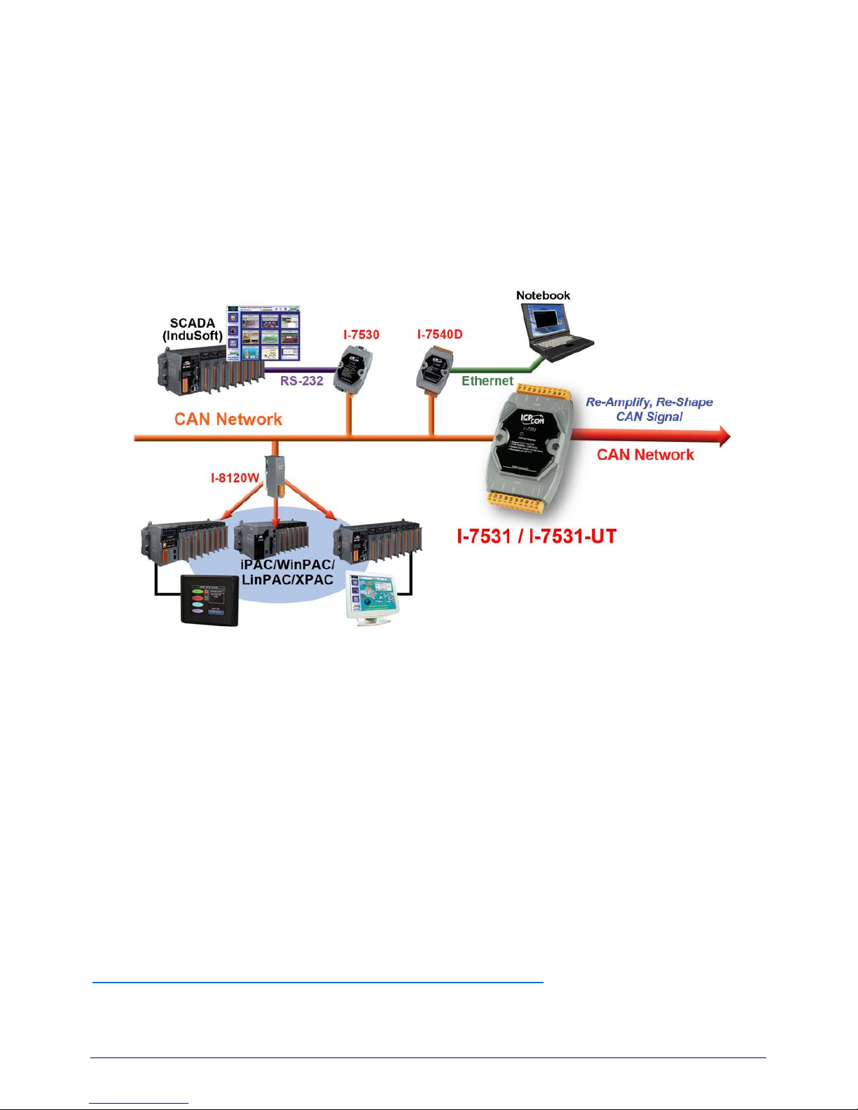
I-7531 / I-7531-UT is a CAN repeater used to establish a physical coupling of two or more
segments of a CAN bus system. User can implement tree or star topologies as well as for long
drop lines with I-7531 / I-7531-UT. Connecting via I-7531 / I-7531-UT , the division of a CAN
system into several subsystems increases the maximum number of bus nodes.
Figure1. Application of I-7531 / I-7531-UT
I-7531 / I-7531-UT is an optically isolated CAN repeater which provides 2500 V
rms
optical
isolation allowing you to separate and protect critical segments of the system from the rest of the
CAN network. And its galvanic isolation isolates both CAN segments from each other as well as
from the power supply. The CAN connection of I-7531 is by terminal blocks. A power supply of 10
~ 30 VDC is required. I-7531 / I-7531-UT is housed in a rugged DIN-Rail mountable box, making it
easy to install in an industrial cabinet. Therefore, I-7531 / I-7531-UT can be used in CANopen,
DeviceNet and generic ISO 11898-2 standard.
If user wants to know more detail information about the I-7531 / I-7531-UT, please visit our
website as follow:
http://www.icpdas.com/products/Remote_IO/can_bus/i-7531.htm

I-7531 & I-7531-UT (CAN Bus Isolated Repeater) User Manual Version 1.6.0 Page:5
Copyright © 2018 ICP DAS Co., Ltd. All Rights Reserved E-mail: service@icpdas.com
1.1 Features
High speed
Removable terminal block & Mountable on DIN Rail
Bus pins protected against transients in an industrial environment
No disturbance of the bus lines with an un-powered node
Transmit data (TxD) dominant time-out function prevents the output drivers from driving
a permanent dominant state
A thermal protection circuit is integrated to prevent the transceiver from damage if the
junction temperature exceeds thermal shutdown level
1.2 Specification
Support CAN 2.0A/CAN 2.0B
Fully compatible with ISO 11898-2
Maximum communication baud : 800Kbps
Propagation Delay: ~200ns
Driving capability: Up to 100 nodes on each CAN port
Photo-coupler isolation between 2 CAN ports: 2500 Vrms
Power consumption: 2W max
CAN terminal resistors are integrated (can be disabled by jumper)
3KV galvanic isolated among of power supply and each CAN port
Power Supply: +10VDC ~ +30VDC
I-7531’s Operating temperature: -25°C ~ +75°C
I-7531-UT’s Operating temperature: -40°C ~ +85°C
Humidity: 5% ~ 95%
Dimensions: 122 mm x 72 mm x 35 mm
1.3 Application
Home Automation
Vehicle Automation
Monitor system
Factory Automation
Building Automation
I-7531 & I-7531-UT (CAN Bus Isolated Repeater) User Manual Version 1.6.0 Page:6
Copyright © 2018 ICP DAS Co., Ltd. All Rights Reserved E-mail: service@icpdas.com
2. Technical data
2.1 Block Diagram
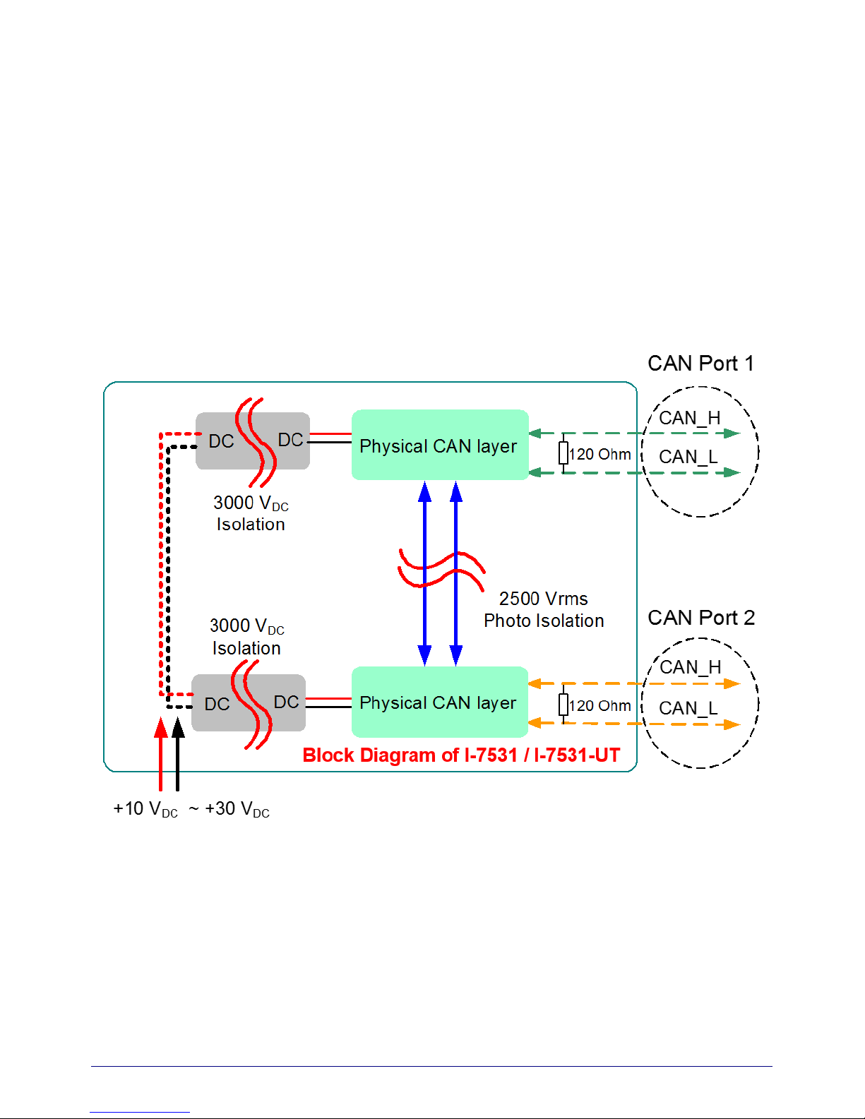
Figure 2 is a block diagram illustrating the functions of the I-7531 module. Power supply are with
3000 VDC galvanic isolated between each CAN port. Futhermore, there is photo-isolation 2500
Vrms between two CAN ports.
Figure2. Block Diagram of I-7531
 Loading...