

Page 1

I-7530A-MR Modbus RTU to CAN Converter User’s Manual (Version 1.07, 06/2016) ------------- 1
User’s Manual
Warranty
All products manufactured by ICP DAS are under warranty regarding
defective materials for a period of one year from the date of delivery to the
original purchaser.
Warning
ICP DAS assumes no liability for damages resulting from the use of this
product. ICP DAS reserves the right to change this manual at any time without
notice. The information furnished by ICP DAS is believed to be accurate and
reliable. However, no responsibility is assumed by ICP DAS for its use, or for
any infringements of patents or other rights of third parties resulting from its use.
Copyright
Copyright 2016 by ICP DAS. All rights are reserved.
Trademark
The names used for identification only may be registered trademarks of
their respective companies.
The I-7530A-MR Modbus RTU to CAN
Converter
Page 2

I-7530A-MR Modbus RTU to CAN Converter User’s Manual (Version 1.07, 06/2016) ------------- 2
Table of Contents
1. Introduction ..................................................................................................................... 4
1.1 Features ....................................................................................................... 6
1.2 Specifications .............................................................................................. 7
2. Hardware .......................................................................................................................... 9
2.1 Block Diagram ........................................................................................... 10
2.2 Pin Assignment ......................................................................................... 11
2.3 Hardware connection ................................................................................ 12
2.3.1 CAN port connection .................................................................................. 12
2.3.2 Serial port connection ................................................................................ 13
2.4 Terminator Resistor Settings .................................................................... 14
2.5 Init / Normal Dip-switch ............................................................................. 15
2.5.1 Firmware Update Mode ............................................................................. 15
2.5.2 Firmware Operation Mode ......................................................................... 17
2.5.3 Module Configuration Mode ....................................................................... 18
2.6 LED Indication ........................................................................................... 18
2.7 Cable Selection .......................................................................................... 20
3. Software Utility .............................................................................................................. 21
3.1 Install the UART2CAN Utility .................................................................... 22
3.2 Configure the module parameters ........................................................... 25
3.2.1 Connect to the I-7530A-MR module with UART2CAN Utility ..................... 25
3.2.2 Select the communication mode ................................................................ 26
3.2.3 Set the COM port parameters .................................................................... 27
3.2.4 Set the CAN parameters ............................................................................ 28
3.2.5 Set the “Pair Connection” parameter ......................................................... 28
3.2.6 Set the “Modbus Slave” parameter ............................................................ 29
3.2.7 Configuration of default value .................................................................... 30
3.2.8 Load/Save the parameter configuration ..................................................... 31
3.3 CAN Filter Configuration .......................................................................... 32
3.3.1 Create New CAN Filter .............................................................................. 32
3.3.2 Download a existed CAN Filter file ............................................................ 35
3.3.3 Read I-7530A-MR CAN Filter Configuration .............................................. 36
3.4 Pair-connection Mode Description .......................................................... 37
3.5 Testing the I-7530A-MR module ............................................................... 43
3.5.1 Normal mode ............................................................................................. 45
3.5.2 Pair Connection Mode ................................................................ ............... 47
3.5.3 Modbus Slave Mode .................................................................................. 48
4. Command list (Only for normal mode) ........................................................................ 50
Page 3

I-7530A-MR Modbus RTU to CAN Converter User’s Manual (Version 1.07, 06/2016) ------------- 3
4.1 tIIILDD…[CHK]<CR> .................................................................................. 52
4.2 TIIIL[CHK]<CR> .......................................................................................... 52
4.3 eIIIIIIIILDD…[CHK]<CR> ............................................................................ 53
4.4 EIIIIIIIIL[CHK]<CR> .................................................................................... 53
4.5 S[CHK]<CR>............................................................................................... 54
4.6 P0BBDSPCR[CHK]<CR> ........................................................................... 55
4.7 P1B [CHK]<CR> ......................................................................................... 58
4.8 P2BBBBB[CHK]<CR> ................................................................................ 59
4.9 RA[CHK]<CR> ............................................................................................ 60
4.10 General Error code for all command ....................................................... 61
5. Modbus Slave Mode ...................................................................................................... 62
5.1 Supported Modbus Functions .................................................................. 64
5.2 Modbus Address ....................................................................................... 64
5.2.1 Using Modbus RTU command to get a CAN Message .............................. 79
5.2.2 Using Modbus RTU command to send a CAN message ........................... 81
5.2.2.1 Using function Code 10
hex
to send a CAN message ...................... 81
5.2.2.2 Using function Code 06
hex
to send a CAN message ...................... 83
5.2.3 Using Modbus RTU command to get a Specific CAN Message................. 86
5.2.4 Using Modbus RTU command to configure module .................................. 87
5.3 Modbus Exception Codes ......................................................................... 89
6. Modbus Master Mode ................................................................................................... 90
6.1 Supported Modbus Functions .................................................................. 90
6.2 IO Memory Size .......................................................................................... 91
6.3 Configuration and Operation .................................................................... 91
6.3.1 Modbus Read Configuration ...................................................................... 92
6.3.1.1 Modbus Read Command.................................................................. 93
6.3.1.2 Response CAN Message Configuration ......................................... 96
6.3.2 Modbus Write Configuration ...................................................................... 99
6.3.3 Common Configuration ............................................................................ 103
7. Troubleshooting .......................................................................................................... 106
Page 4
I-7530A-MR Modbus RTU to CAN Converter User’s Manual (Version 1.07, 06/2016) ------------- 4
1. Introduction
The I-7530A-MR is helpful for exchanging the data between the RS232/485/422 devices and the CAN devices. It supports four
communication modes: “Normal”, “Modbus Slave” , “Pair connection”, and
“Modbus Master” (firmware version v1.11 or later).
In the Normal mode, the I-7530A-MR is designed to unleash the power of
CAN bus via RS-232/485/422 communication method. It accurately
converts ASCII format messages and CAN messages between RS232/485/422 and CAN networks. This mode let you to communicate with
CAN devices easily from any PC or programmable devices with RS232/485/422 interface.
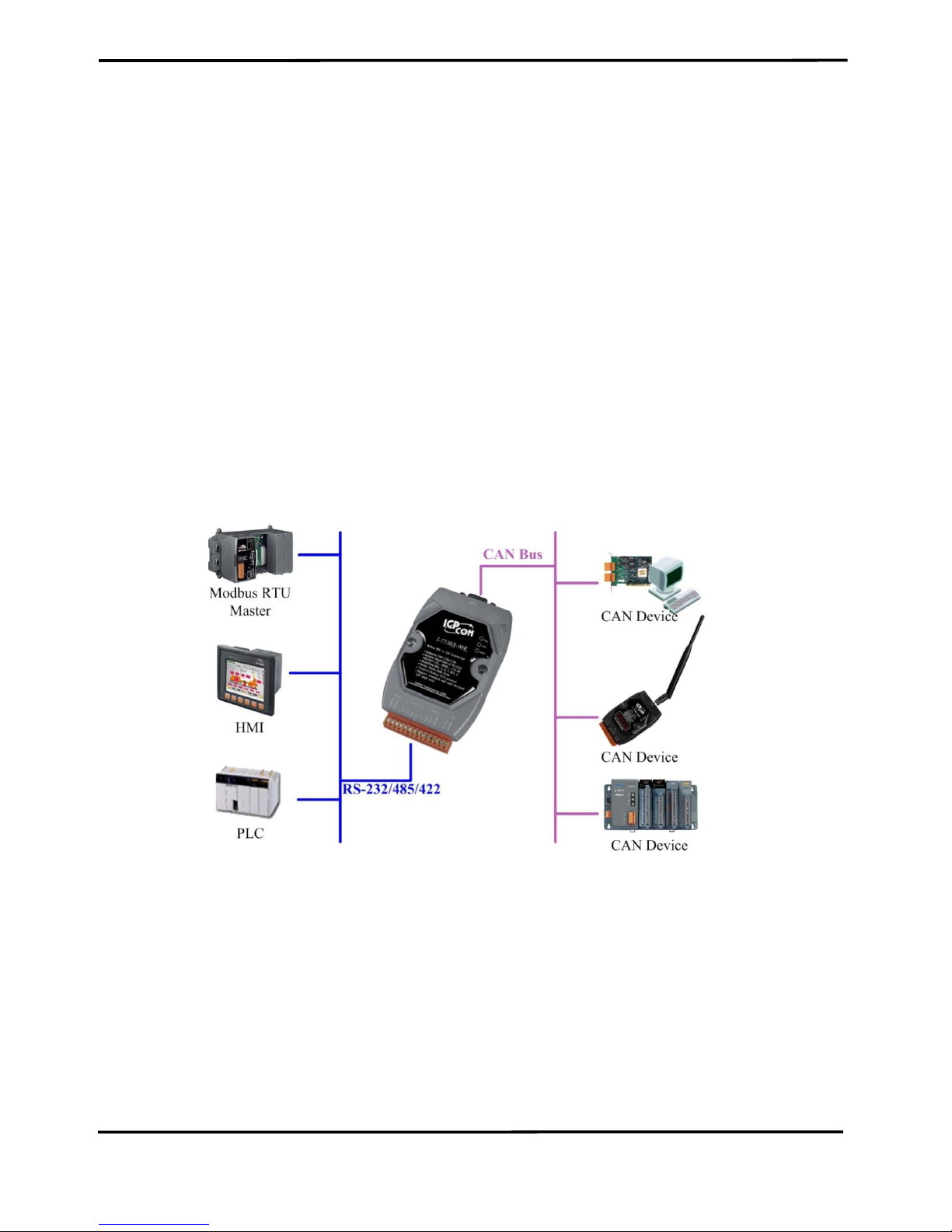
In the Modbus Slave mode, it allows a Modbus RTU master to
communicate with CAN devices on a CAN network. The following figure
shows the application architecture in this mode.
Figure 1-1: The application architecture in the Modbus Slave mode.
Page 5

I-7530A-MR Modbus RTU to CAN Converter User’s Manual (Version 1.07, 06/2016) ------------- 5
In the pair-connection mode, this module provides the transparent
communication between the RS-232/485/422 devices via CAN bus. The
application architecture may be as follows.
Figure 1-2: The application architecture in the pair-connection mode.
In the Modbus Master mode, it allows many Modbus RTU slaves to
communicate with CAN devices on a CAN network. The following figure
shows the application architecture in this mode.
Figure 1-3: The application architecture in the Modbus Master mode.
Page 6

I-7530A-MR Modbus RTU to CAN Converter User’s Manual (Version 1.07, 06/2016) ------------- 6
1.1 Features
RoHS Design
Fully compatible with ISO 11898-2 standard
Programmable CAN bus baud rate from 10 kbps to 1 Mbps or user-
defined baud rate
Max transmission speed of RS-232/485/422 port up to 230400 bps
Support CAN bus acceptance filter configuration
Support firmware update via RS-232
Utility tool for module configuration and CAN bus communication
testing
Built-in jumper to select 120Ω terminator resistor
CAN buffer: 128 data frames; UART buffer: 256 bytes.
Power, data flow and error indicator for CAN and UART status
Hardware Watchdog design
Allow special ASCII commands to send and receive CAN messages
(Normal mode)
Provide the transparent communication in the RS-232/485/422 port
through the CAN bus (Pair-connection mode)
In Modbus Slave mode, I-7530A-MR supports function code 0x03,
0x04, 0x06 (firmware version v1.11 or later), and 0x10 of Modbus RTU
command for reading or writing CAN message (Modbus Slave mode).
Besides, function code 0x10 has additional functions for configuring
module.
Support Modbus Master function (firmware version v1.11 or later).
Page 7

I-7530A-MR Modbus RTU to CAN Converter User’s Manual (Version 1.07, 06/2016) ------------- 7
1.2 Specifications
UART specification:
Connector: 14-pin screw terminal connector
COM1: RS-232: (TxD, RxD, GND)
RS-422: (TxD+, TxD-, RxD+, RxD-)
RS-485: (DATA+, DATA-)
Baud Rate(bps): 300, 600, 1200, 2400, 4800, 9600, 19200, 38400,
57600, 115200, 230400
Data/Stop bits: 5, 6, 7, 8 / 1, 2
Parity bit: None, Odd, Even
Isolation voltage: 3000 VDC power protection and 2500V
rms
photo-
couple in the UART side
CAN specification:
CAN interface connector: 9-pin male D-sub (CAN_L, CAN_H,
CAN_GND, and N/A for others)
CAN Baud Rate(bps): 10 k, 20 k, 50 k, 100 k, 125 k, 250 k, 500 k, 800
k and 1 M (allow user-defined baud rate)
Isolation voltage: 3000 VDC power protection on CAN side, 3750V
rms
photo-couple on CAN bus
Terminator Resistor: Jumper for 120Ω terminator resistor
Support Protocol: ISO-11898-2, CAN 2.0A and CAN 2.0B
Power requirement:
Unregulated +10V DC ~ +30V DC
Power consumption: 1.5W
DIP switch: Init (Firmware Update, Module Configuration) / Normal
(Firmware Operation)
Module specs:
Dimensions: 72mm x 118mm x 35mm (W x L x H)
Operating temperature: -25 to 75ºC (-13 to 167ºF)
Storage temperature: -30 to 80ºC (-22 to 176ºF)
Humidity: 10 to 95%, non-condensing
LEDs: PWR LED for power
CAN LED for CAN bus communication
UART LED for UART communication
Page 8

I-7530A-MR Modbus RTU to CAN Converter User’s Manual (Version 1.07, 06/2016) ------------- 8
Software Utility tool:
CAN bus baud rate configuration
CAN acceptance filter configuration
CAN 2.0A or 2.0B specific selection
RS-232/485/422 baud rate and data format configuration
Checksum function selection of the RS-232/485/422 communication
Communication mode setting
Function for transmitting or receiving CAN messages
Application:
Factory Automation
Building Automation
Home Automation
Control system
Monitor system
Vehicle Automation
Page 9

I-7530A-MR Modbus RTU to CAN Converter User’s Manual (Version 1.07, 06/2016) ------------- 9
2. Hardware
Figure 2-1: Hardware profile of the I-7530A-MR
Page 10
I-7530A-MR Modbus RTU to CAN Converter User’s Manual (Version 1.07, 06/2016) ------------- 10
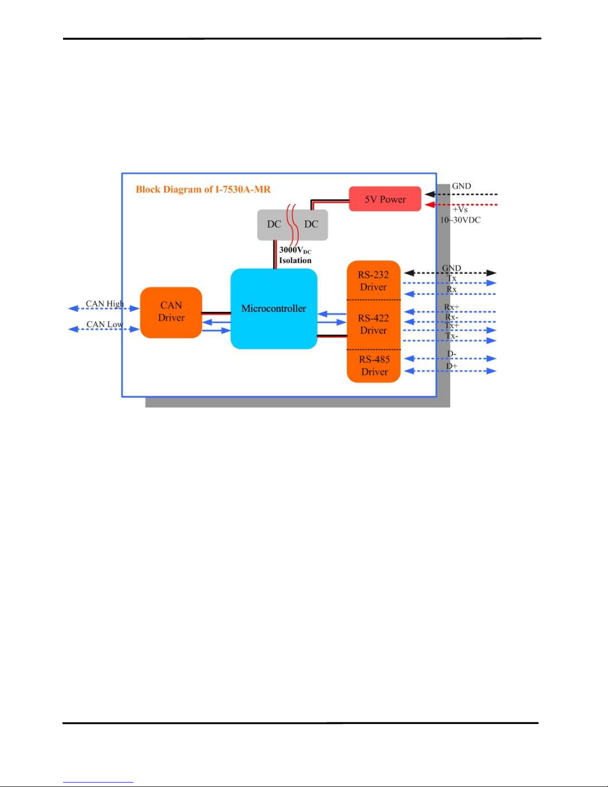
2.1 Block Diagram
Figure 2-2 is a block diagram illustrating the functions of the I-7530AMR module. It provides the 3000VDC Isolation in the CAN and UART
interface. And hardware media in RS-232 interface only adopts 3-wire
connection.
Figure 2-2: Block diagram of I-7530A-MR
Page 11
I-7530A-MR Modbus RTU to CAN Converter User’s Manual (Version 1.07, 06/2016) ------------- 11
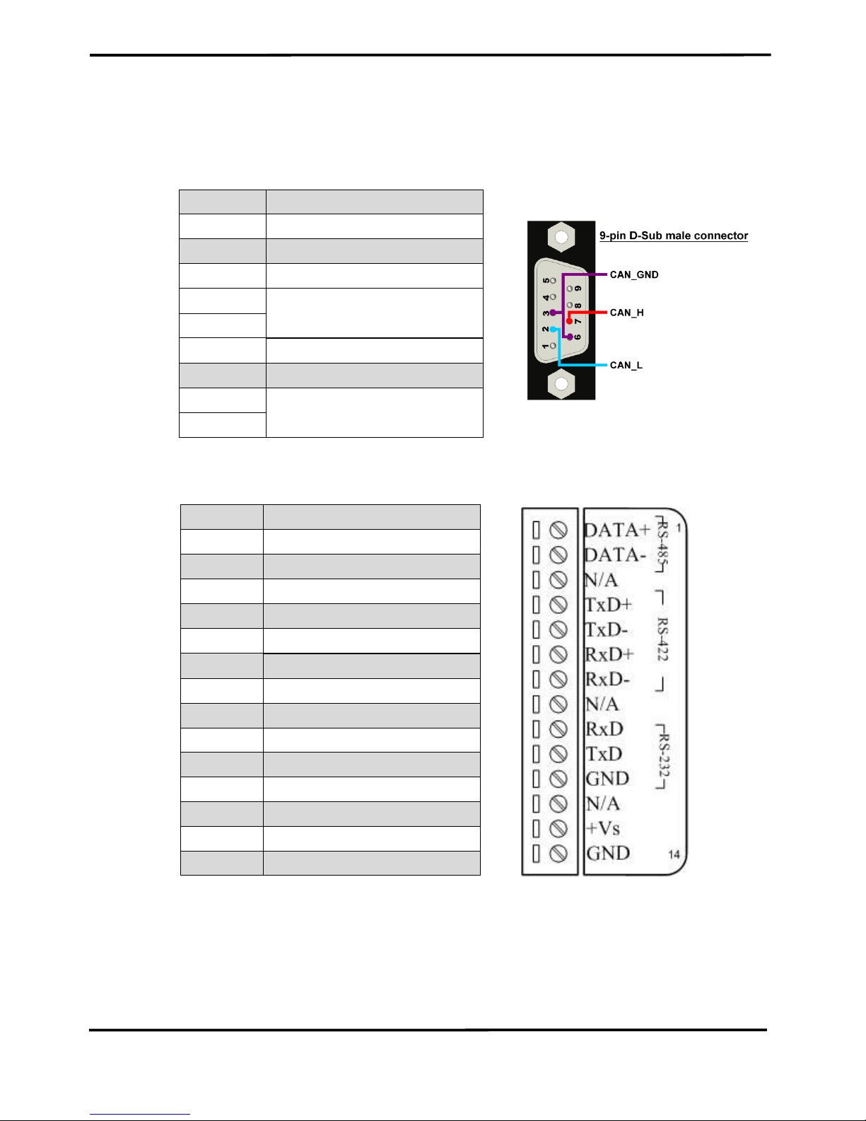
2.2 Pin Assignment
Table 2-1: CAN DB9 Male Connector
Pin
Description
1
Not Connect
2
CAN Low
3
CAN Ground
4
Not Connect
5 6 CAN Ground
7
CAN High
8
Not Connect
9
Figure 2-3: Pin Assignment on the I-7530A-MR
Pin
Description
1
RS-485 DATA+
2
RS-485 DATA-
3
No use
4
RS-422 TxD+
5
RS-422 TxD-
6
RS-422 RxD+
7
RS-422 RxD-
8
No use
9
RS-232 RXD
10
RS-232 TXD
11
RS-232 GND
12
No use
13
+Vs(+10 ~ +30 VDC)
14
GND
Page 12
I-7530A-MR Modbus RTU to CAN Converter User’s Manual (Version 1.07, 06/2016) ------------- 12
2.3 Hardware connection
The I-7530A-MR module supports CAN/Serial port communication, it
offers one CAN interface for CAN network and RS-232/485/422 interfaces
for serial communication.
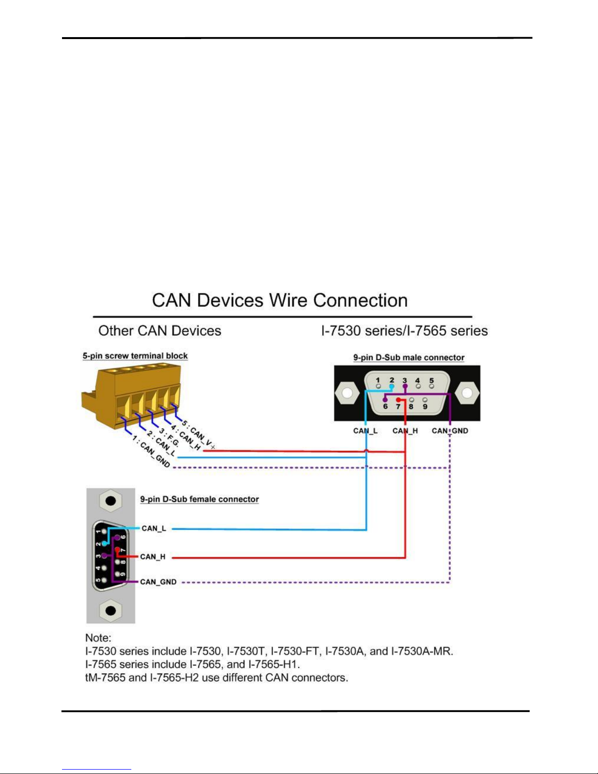
2.3.1 CAN port connection
The pin assignment of the CAN port of the I-7530A-MR (DB9 male) is
defined in both the CANopen DS102 profile and in appendix C of the
DeviceNet specifications. It is the standard pin assignment for CAN
interface. The hardware connection between the target device and the I7530A-MR is shown as Figure 2-4.
Figure 2-4: CAN Hardware Wire Connection
Page 13

I-7530A-MR Modbus RTU to CAN Converter User’s Manual (Version 1.07, 06/2016) ------------- 13
2.3.2 Serial port connection
The I-7530A-MR offers three serial interfaces. It is recommended to
use only one of them at the same time. The following figures describe
these port types and the wiring method for a serial device.
Figure 2-5: RS-232 Wire Connection
Figure 2-6: RS-422 Wire Connection
Figure 2-7: RS-485 Wire Connection
Page 14
I-7530A-MR Modbus RTU to CAN Converter User’s Manual (Version 1.07, 06/2016) ------------- 14
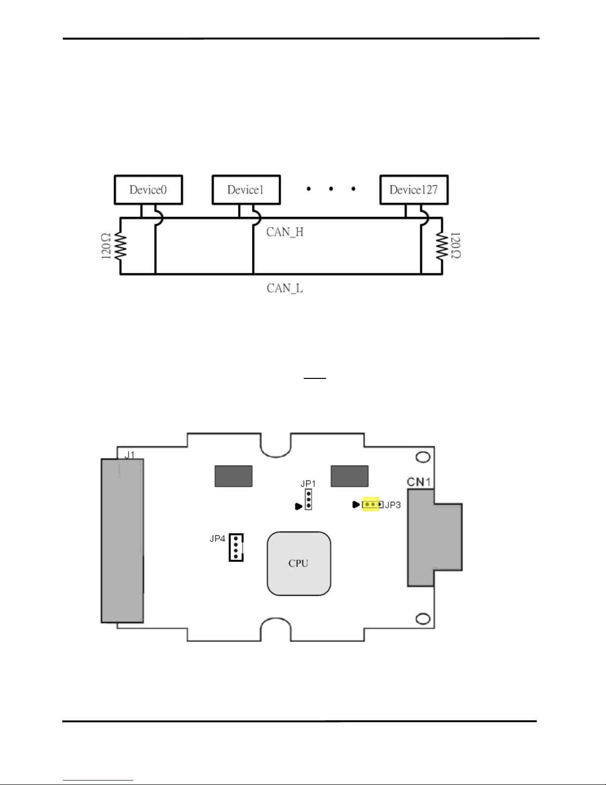
2.4 Terminator Resistor Settings
According to the ISO 11898 specifications, the CAN Bus network
must be terminated by two terminal resistors (120Ω). They are shown as
following figure.
Figure 2-8: Terminal Resistor
Therefore, the I-7530A-MR module supplies a jumper for activating
the terminal resistor. If users want to use this terminal resistor, please
open the I-7530A-MR cover and use the JP3 to activate the 120Ω terminal
resistor built in the module, as the Figure 2-9. Note that the default setting
is active.
Figure 2-9: Terminal Resistor Jumper
Page 15
I-7530A-MR Modbus RTU to CAN Converter User’s Manual (Version 1.07, 06/2016) ------------- 15
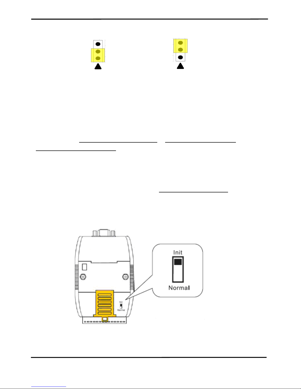
Enable (default) Disable
Figure 2-10: Terminal resistor JP3 Jumper Position
2.5 Init / Normal Dip-switch
On the back of the I-7530A-MR module, there is a DIP-switch used to
configure the “firmware operation mode”, “firmware update mode” or
“module configuration mode”. The following steps show how to use it.
2.5.1 Firmware Update Mode
Please set the DIP-switch to the “Init” (Initial) position as Figure 2-12,
and then the I-7530A-MR will work in the “Firmware Update Mode” after
resetting the power of the module. In the firmware update mode, users
can update the firmware of the I-7530A-MR module from computer’s RS232 port via CA-0910 cable, as Figure 2-12~2-14.
Figure 2-12: Init Position of DIP-Switch
Page 16

I-7530A-MR Modbus RTU to CAN Converter User’s Manual (Version 1.07, 06/2016) ------------- 16
Figure 2-13: CA-0910 Cable
Figure 2-14: Firmware downloads connection
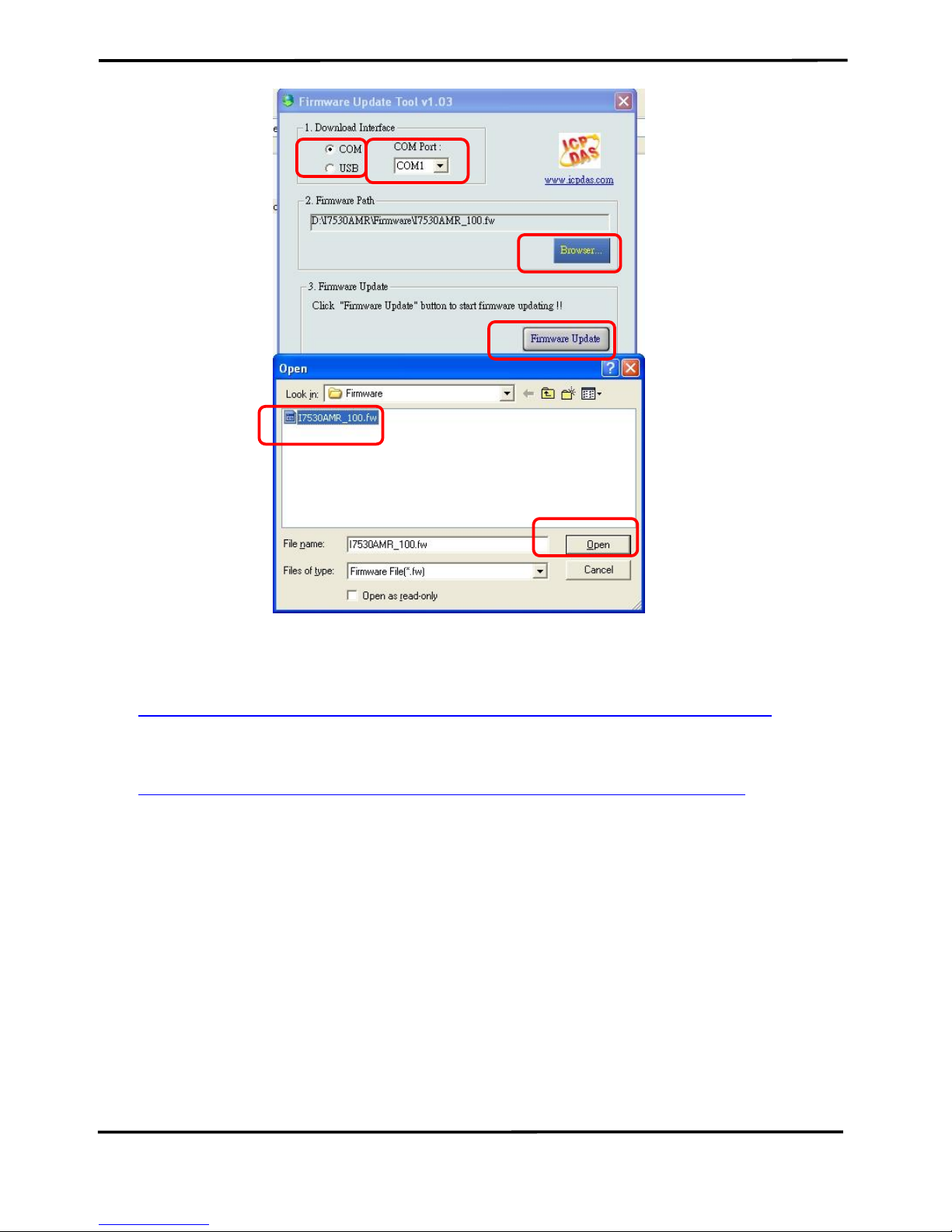
While updating the firmware, users need to execute
“Firmware_Update_Tool.exe”. The following steps show the update
procedure.
[1] Run the Firmware_Update_Tool.exe.
[2] Choose “COM” interface and “COM Port”.
[2] Click “Browser” button to choose the firmware file.
(e.g. I7530AMR_100.fw)
[3] Click “Firmware Update” button to start firmware update process.
Page 17
I-7530A-MR Modbus RTU to CAN Converter User’s Manual (Version 1.07, 06/2016) ------------- 17
Figure 2-15: I-7530A-MR firmware update process
The I-7530A-MR firmware can be downloaded from
http://ftp.icpdas.com/pub/cd/fieldbus_cd/can/converter/i-7530a-mr/firmware/
The “Firmware_Update_Tool” program can be downloaded from
http://ftp.icpdas.com/pub/cd/fieldbus_cd/can/converter/i-7530a-mr/utility/
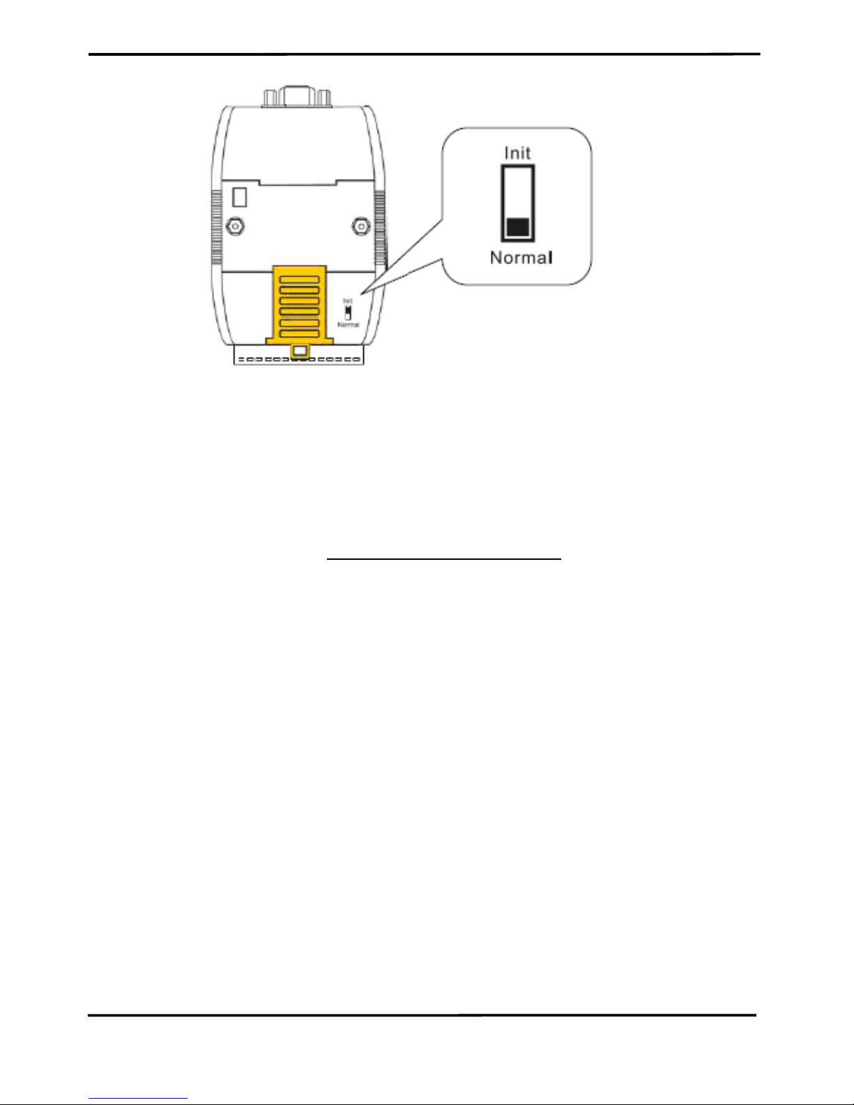
2.5.2 Firmware Operation Mode
Please set the DIP-switch to the “Normal” position as Figure 2-16 and
power on the I-7530A-MR module. The module’s PWR LED always
turned on and the others LEDs are turned off. That means the I-7530AMR module is working in the operation mode. In this mode, users can use
the RS-232/485/422 device to send/receive CAN messages via COM port.
1 2 3
4
6
5
Page 18
I-7530A-MR Modbus RTU to CAN Converter User’s Manual (Version 1.07, 06/2016) ------------- 18
Figure 2-16: Normal Position of Dip-Switch
2.5.3 Module Configuration Mode
During the module is running in the Firmware Operation Mode, set the
DIP-switch to the “Init” (Initial) position as Figure 2-12 and wait for three
seconds. The module’s PWR LED still turns on and the others LEDs will
flash approximately once per second. That means the I-7530A-MR
module is working in the “Module Configuration Mode”. In this mode,
users can use UART2CAN Utility to configure the communication
parameters and communication modes of the module.
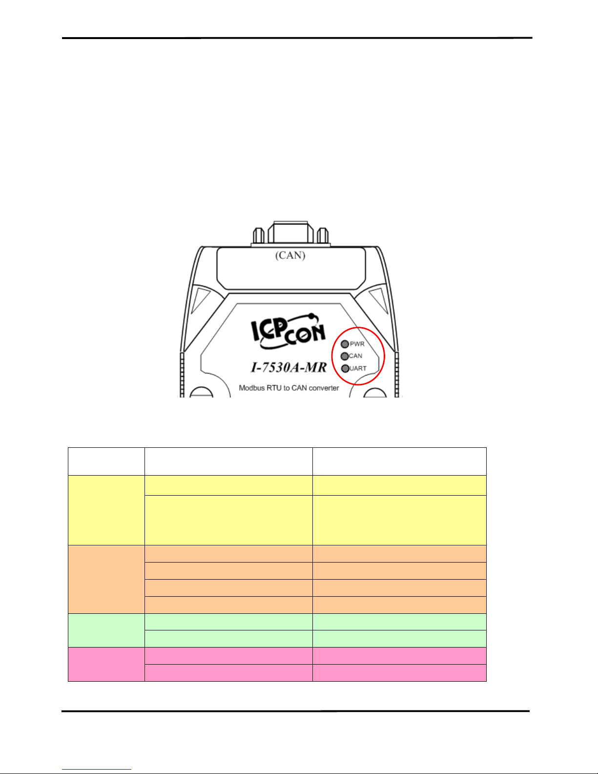
2.6 LED Indication
There are three LEDs to indicate what the state of the I-7530A-MR is
in. The positions of these three LEDs are shown as Figure 2-17.
(1) PWR LED :
It is used to help users with checking if the I-7530A-MR is standby. If
the module is supplied the proper power, the PWR LED is turned on. The
different situations of the module may cause the different blinking display.
The PWR LED is always turned on when the module works in a good
condition. When the Bus-Off error is happened, the PWR LED will blink
every 500 ms until the Bus-Off condition disappears. If the CAN message
can’t be sent out successfully, the PWR LED will blink every 100 ms.
Page 19
I-7530A-MR Modbus RTU to CAN Converter User’s Manual (Version 1.07, 06/2016) ------------- 19
(2) CAN LED :
It is used to show whether the I-7530A-MR is transmitting/receiving
CAN messages. The CAN LED will blink whenever a CAN message is
sending or receiving.
(3) UART LED :
It is used to show whether the I-7530A-MR is transmitting/receiving
COM messages. The UART LED will blink whenever a COM message is
sending or receiving.
Figure 2-17: LED position of the I-7530A-MR
Table 2-3: LED indication of the I-7530A-MR
LED Name
I-7530A-MR Status
LED Status
ALL LEDs
Firmware Updating Mode
All LED always turned on
Module Configuration Mode
PWR LED always be turned
on and the other LEDs blink
every 1000 ms
PWR LED
No Error
Always turned on
CAN Bus Transmission Fail
Blink every 100 ms
CAN Bus-Off
Blink every 500 ms
Power Failure
Off
CAN LED
Transmission
Blink
Bus Idle
Off
UART LED
Transmission
Blink
Bus Idle
Off
Page 20

I-7530A-MR Modbus RTU to CAN Converter User’s Manual (Version 1.07, 06/2016) ------------- 20
2.7 Cable Selection
The CAN bus is a balanced (differential) 2-wire interface running over
either a Shielded Twisted Pair (STP), Un-shielded Twisted Pair (UTP), or
Ribbon cable. The CAN-L and CAN-H Wire start on one end of the total
CAN network that a terminator of 120 Ohm is connected between CAN-L
and CAN-H. The cable is connected from CAN node to CAN node,
normally without or with short T connections. On the other end of the
cable again a 120Ω(Ohm) terminator resistor is connected between the
CAN lines. How to decide a cable type, cable length, and terminator
depends on the baud rate in the CAN bus network, please refer to the
following table 2-4.
Figure 2-18: Un-shielded Twisted Pair (UTP)
Table 2-4: Cable selection
Bus speed
Cable type
Cable
Resistance/m
Terminator
Bus Length
50k bit/s
at 1000m
0.75~0.8mm2
18AWG
70 mOhm
150~300
Ohm
600~1000m
100k bit/s
at 500m
0.5~0.6 mm2
20AWG
< 60 mOhm
150~300
Ohm
300~600m
500k bit/s
at 100m
0.34~0.6mm2
22AWG, 20AWG
< 40 mOhm
127 Ohm
40~300m
1000k bit/s
at 40m
0.25~0.34mm2
23AWG, 22AWG
< 40 mOhm
124 Ohm
0~40m
Note: The AWG means a standard method used to measure wire. The
numbering system works backwards from what people would think, the
thicker (heavier) the wire, the lower the number. For example: a 24AWG
wire is thicker/heavier than a 26AWG wire.
Page 21
I-7530A-MR Modbus RTU to CAN Converter User’s Manual (Version 1.07, 06/2016) ------------- 21
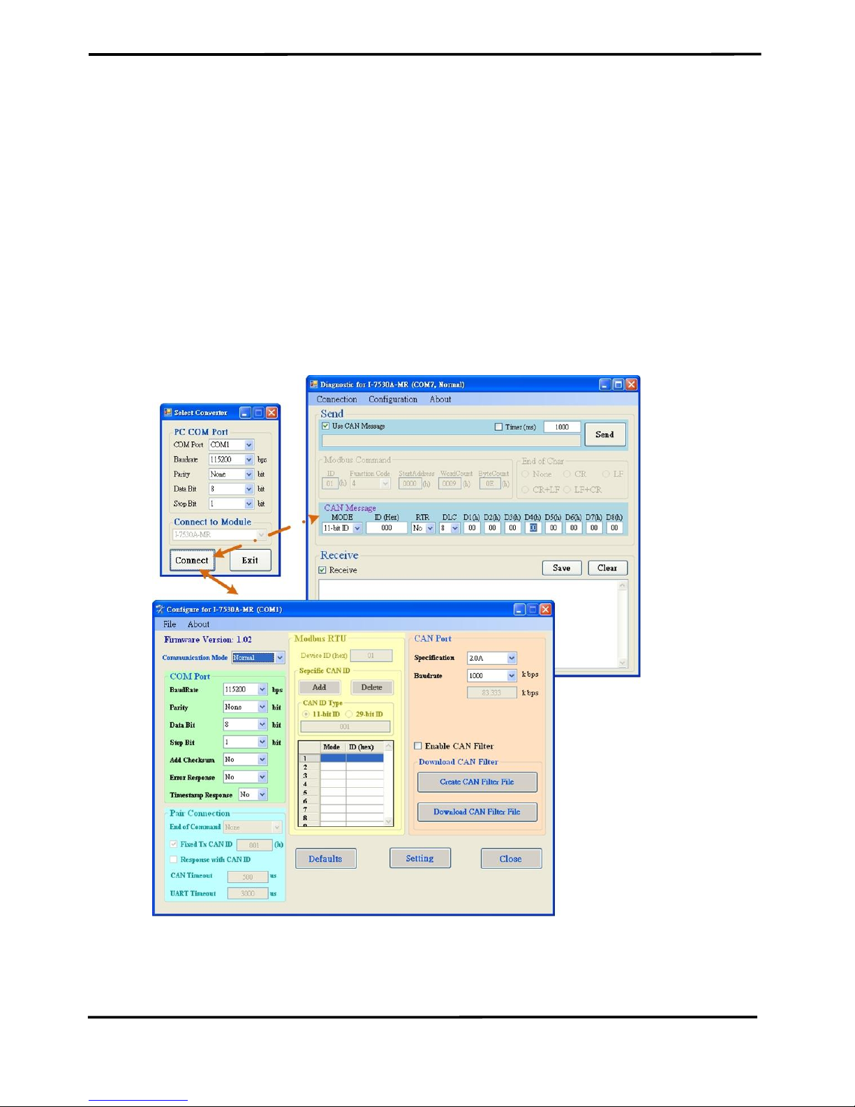
3. Software Utility
The UART2CAN Utility tool can be used to configure the operational
conditions of the I-7530A-MR between the CAN and RS-232/485/422
communications. It also can used to transmit or receive a CAN message
for simple testing. To start the “UART2CAN Utility”, please install the
UART2CAN Utility setup file and run the UART2CAN_Utility.exe file. The
screenshot of the configuration and testing screen are given in the below
figure. The next section will show you how to configure the I-7530A-MR
and test it by using UART2CAN Utility.
Figure 3-1: Configuration and testing screen for UART2CAN Utility.
Page 22

I-7530A-MR Modbus RTU to CAN Converter User’s Manual (Version 1.07, 06/2016) ------------- 22
3.1 Install the UART2CAN Utility
Step 1: Get the UART2CAN Utiltiy
The software is located at:
Fieldbus_CD:\CAN\Converter\I-7530A-MR\Utility
http://ftp.icpdas.com/pub/cd/fieldbus_cd/can/converter/i-7530a-mr/utility/
Step 2: Install .NET Framework 4 Client Profile component
The UART2CAN Utility tool requires the Windows Installer 3.1 and
the .NET Framework 4 Client Profile components. These components can
be obtained from the web site.
Windows Installer 3.1:
http://ftp.icpdas.com/pub/cd/fieldbus_cd/can/converter/i-7530amr/utility/windowsinstaller3_1/
.NET Framework 4 Client Profile:
http://ftp.icpdas.com/pub/cd/fieldbus_cd/can/converter/i-7530amr/utility/dotnetfx40client/
Figure 3-2: Setup the Windows Installer and .NET Framework.
Page 23
I-7530A-MR Modbus RTU to CAN Converter User’s Manual (Version 1.07, 06/2016) ------------- 23
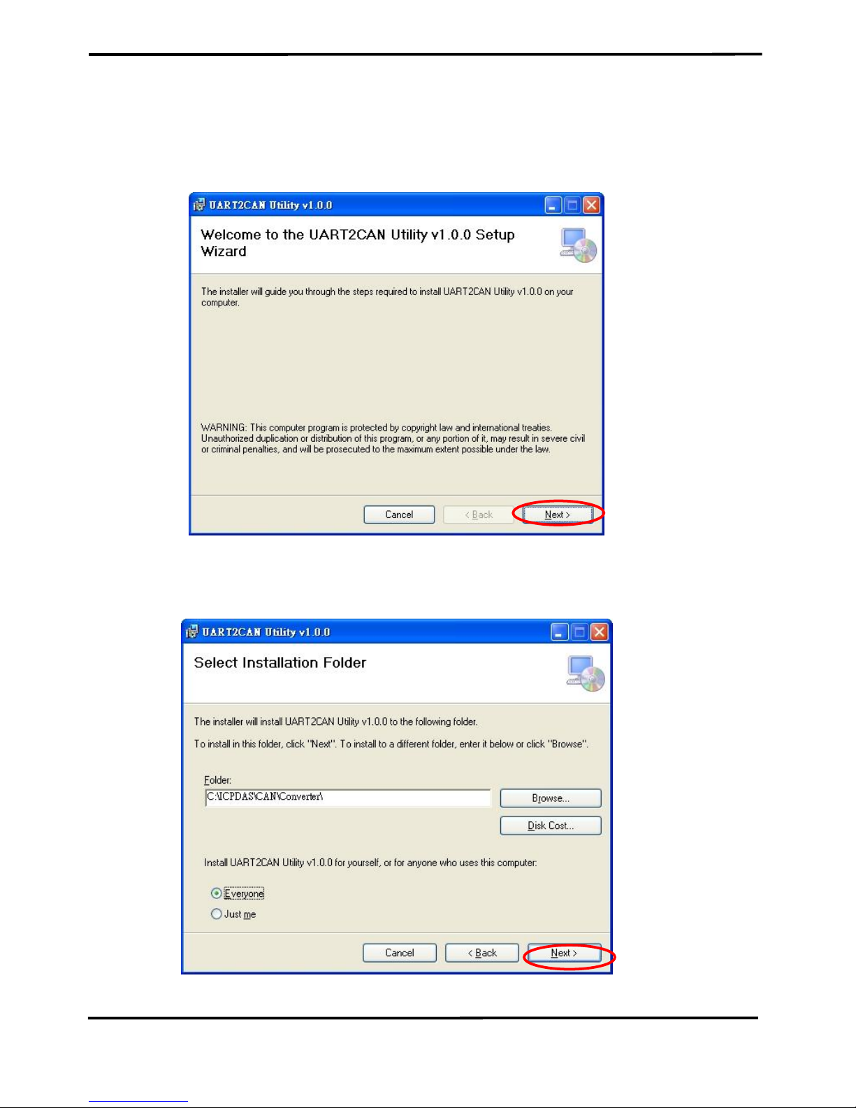
Step 3: Install Utility tool
After installing the .Net Framework components, please run the
UART2CAN Utility setup file.
1. Click the “Next” button to continue.
Figure 3-3: Setup the UART2CAN Utility.
2. Select the installation path of the UART2CAN Utility and click the
“Next” button.
Figure 3-4: Select Installation Folder.
Page 24
I-7530A-MR Modbus RTU to CAN Converter User’s Manual (Version 1.07, 06/2016) ------------- 24
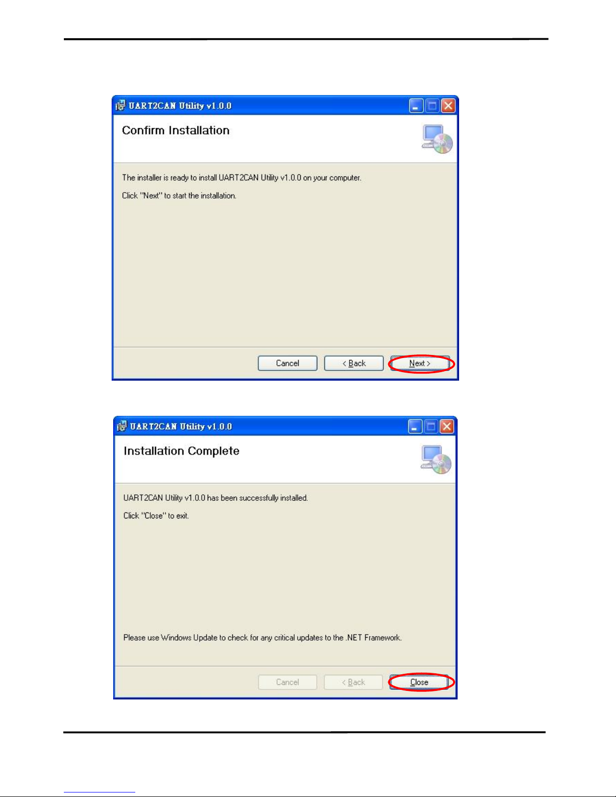
3. Confirm the installation. Click the “Next” button to start the
installation.
Figure 3-5: Confirm Installation.
4. Installation complete. Click the “Close” button to exit.
Figure 3-6: Installation complete.
Page 25
I-7530A-MR Modbus RTU to CAN Converter User’s Manual (Version 1.07, 06/2016) ------------- 25
3.2 Configure the module parameters
In this section, we will describe how to configure the communication
parameters of the I-7530A-MR module with the UART2CAN Utility.
3.2.1 Connect to the I-7530A-MR module with UART2CAN Utility
1. Set the Init/Normal switch to the “Normal” position, which is found
on the back of the I-7530A-MR module.
2. Supply the proper electric power (the 10~30 DC volts) to the I7530A-MR module.
3. Set the Init/Normal switch to the “Init” (Initial) position at least three
seconds.
4. The PWR LED of the I-7530A-MR module will turned on and the
other LEDs will flash approximately once per second. That means
the I-7530A-MR module is working in the configuration mode.
5. Run the UART2CAN Utility software after connecting the PC COM
port and the I-7530A-MR RS-232 port by the cable CA-0910.
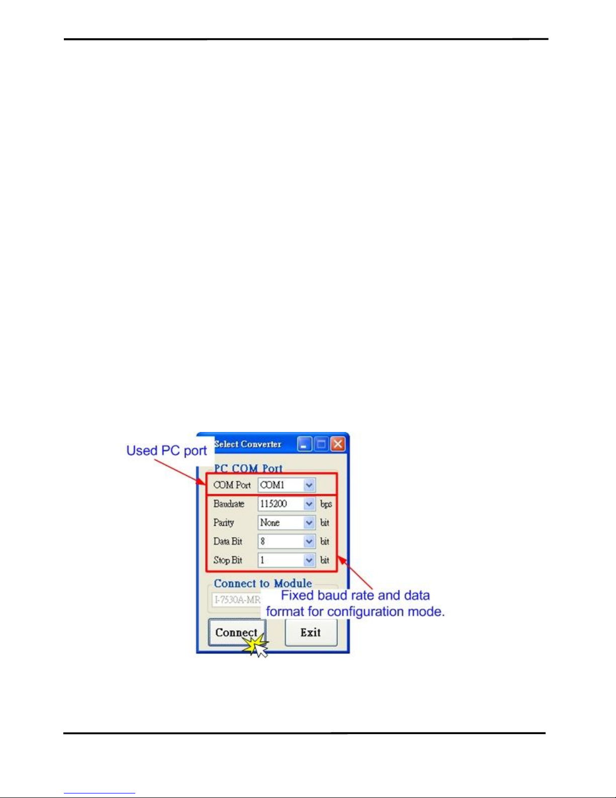
6. Select the necessary PC COM port to connect with the I-7530A-MR,
as shown in the following figure. Then click the “Connect” button.
Figure 3-7: The PC’s COM port configuration form.
Note: When the I-7530A-MR is working in the configuration mode, it can
only be communicated by using 115200 baud rate.
Page 26
I-7530A-MR Modbus RTU to CAN Converter User’s Manual (Version 1.07, 06/2016) ------------- 26
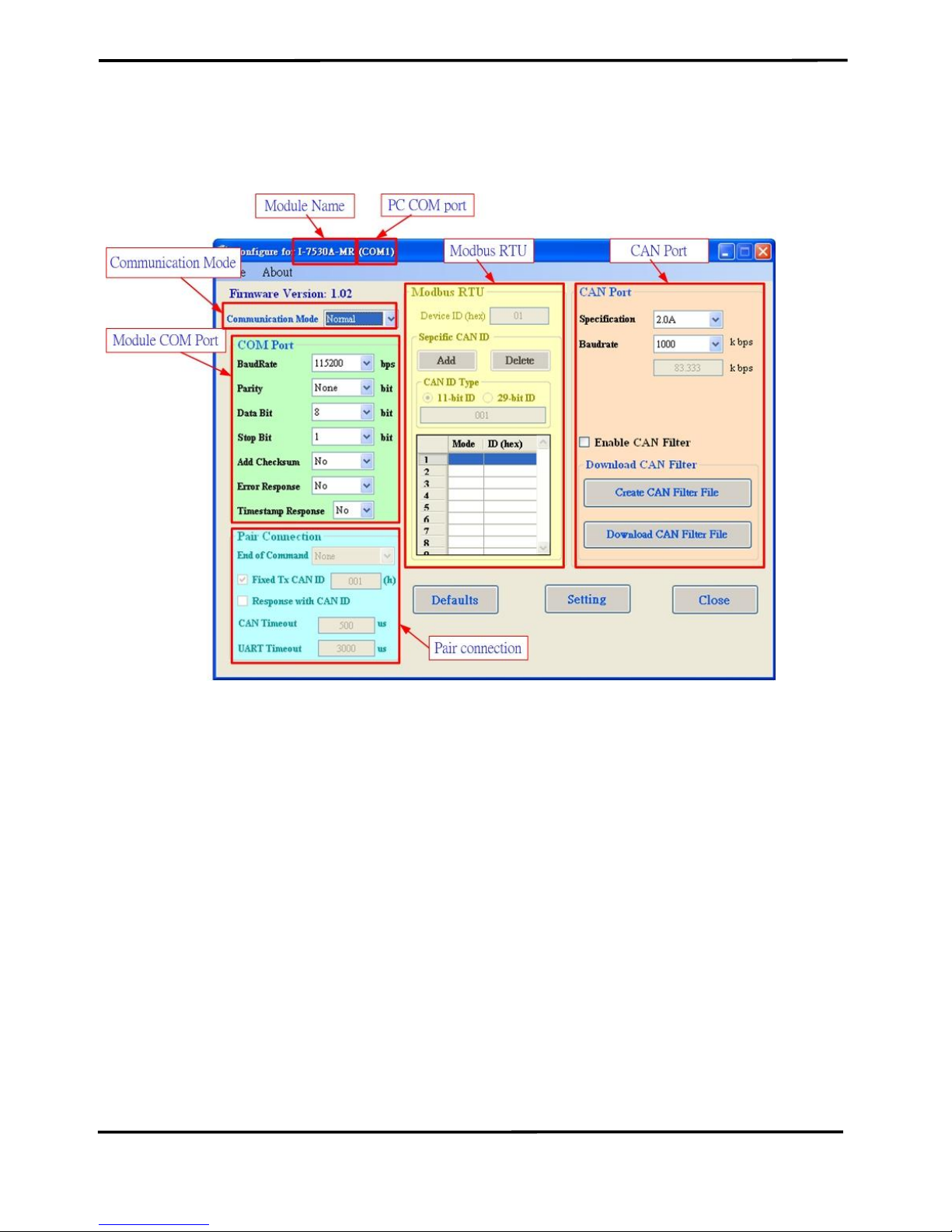
7. Then the I-7530A-MR configuration window will be brought out. The
UART2CAN Utility will show the communication information of the I7530A-MR module, as shown in the following figure.
Figure 3-8: The configuration form of the I-7530A-MR module.
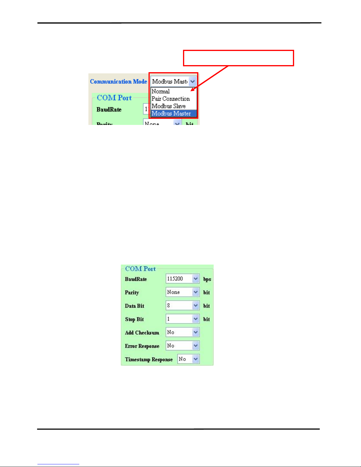
3.2.2 Select the communication mode
The I-7530A-MR supports four communication modes: “Normal”, “Pair
connection”, “Modbus Slave”,and “Modbus Master Mode”.
In the Normal mode, it accurately converts ASCII format messages
and CAN messages between RS-232/485/422 and CAN interfaces. In the
Modbus Slave mode, it allows a Modbus master to communicate with
CAN devices on a CAN network. In pair-connection mode, this module
provides the transparent communication between the RS-232/485/422
devices via CAN bus. In the Modbus Master mode, this module is worked
as Modbus Master/CAN module. It can communicate with Modbus slave
device via RS-232/485/422.
Page 27
I-7530A-MR Modbus RTU to CAN Converter User’s Manual (Version 1.07, 06/2016) ------------- 27
Figure 3-9: Select Communication Mode.
3.2.3 Set the COM port parameters
1. When the function “Add Checksum” is set to “Yes”, users need to
communicate to the I-7530A-MR with checksum mechanism. (For
checksum algorithm, please refer to page 51)
2. If the “Error Response” is set to “Yes”, the error code will be
responded when the incorrect communication commands are sent to
the I-7530A-MR.
3. If the “Timestamp Response” is set to “Yes”, the timestamp value will
be responded when the CAN message commands are sent out from
the COM port of I-7530A-MR.
These three parameters above can only use at the “Normal”
communication mode.
Figure 3-10: The COM port of I-7530A-MR configuration.
Select Communication mode
Page 28
I-7530A-MR Modbus RTU to CAN Converter User’s Manual (Version 1.07, 06/2016) ------------- 28
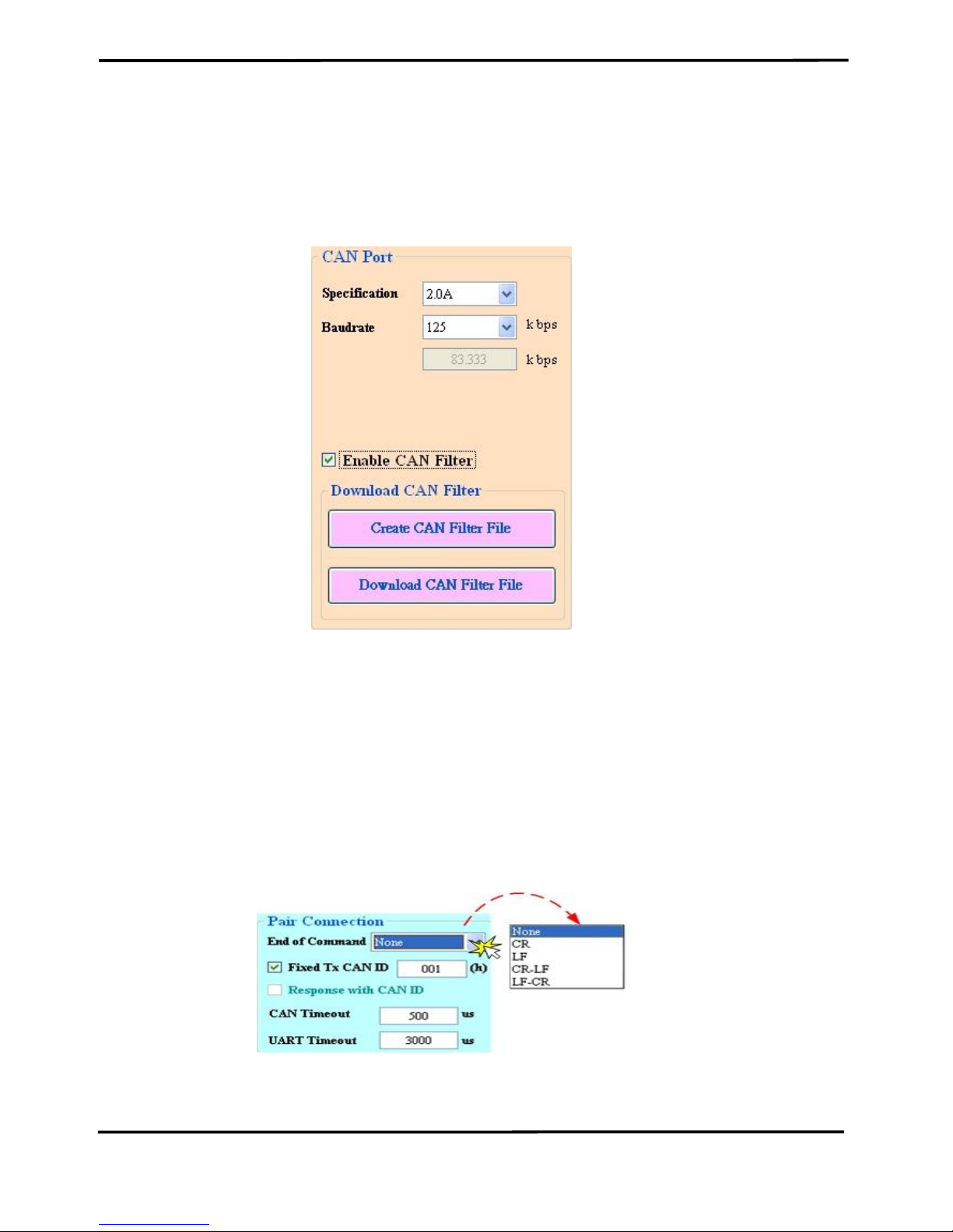
3.2.4 Set the CAN parameters
Select the communication parameters of the CAN port and check the
“Enable CAN Filter” item to make the CAN filter enable if necessary.
About how to set the CAN Filter, please refer to the section 3.3.
Figure 3-11: The CAN port of I-7530A-MR configuration.
3.2.5 Set the “Pair Connection” parameter
When users select the “Pair Connection” communication mode, the
functions, “End of Command”, “Fixed Tx CAN ID” and “Response with
CAN ID”, are useful. In pair connection mode, all commands written to I7530A-MR COM port will be transferred to the CAN bus directly. For more
detail information about pair connection mode, please refer to the section
3.4.
Figure 3-12: The configuration for Pair connection.
Page 29
I-7530A-MR Modbus RTU to CAN Converter User’s Manual (Version 1.07, 06/2016) ------------- 29
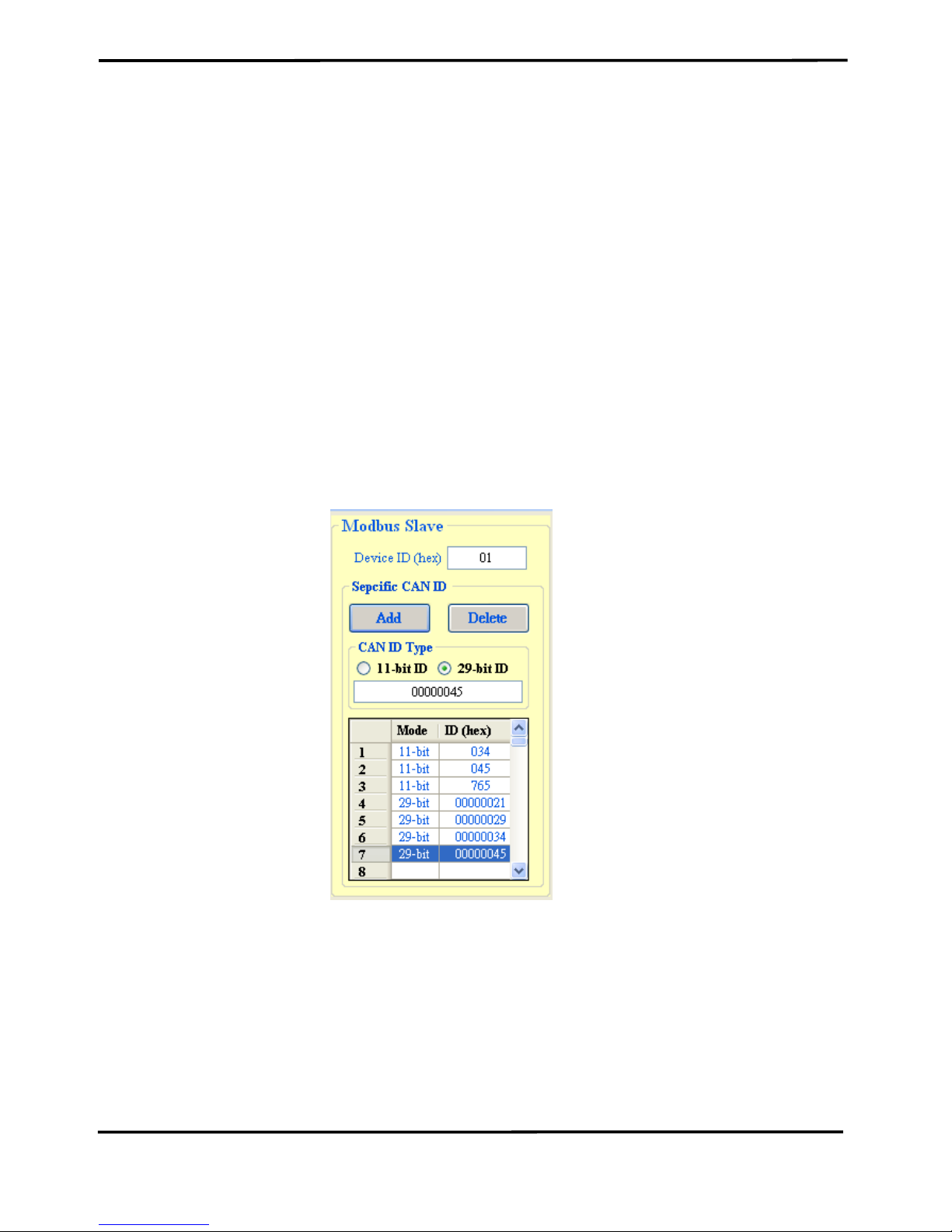
3.2.6 Set the “Modbus Slave” parameter
When users select the “Modbus Slave” communication mode, the
functions, “Device ID” and “Specific CAN ID”, are useful. In the “Specific
CAN ID” field, users can set maximum 10 CAN IDs (firmware v1.02 or
later supports 100 CAN ID of CAN messages) which indicate the
corresponding CAN messages to be stored in the specific Modbus Input
Register respectively. In the Modbus Input Register, the register range of
the “Specific CAN ID” occupies the section from 0x0800 to 0x0859. Each
CAN ID will use 9 Modbus input registers.
In Modbus Slave mode, users need to communicate with the I-7530AMR via using Modbus RTU command. The I-7530A-MR only supports
function code 03/04/06/10 of Modbus RTU commands for reading and
writing CAN messages. For more details about Modbus Slave mode,
please refer to the section 5.
Figure 3-13: The configuration for Modbus Slave mode.
Page 30

I-7530A-MR Modbus RTU to CAN Converter User’s Manual (Version 1.07, 06/2016) ------------- 30
3.2.7 Configuration of default value
If users click the “Defaults” button, all of the module communication
parameters on the I-7530A-MR will be set to the factory default, which are:
Communication Mode = Normal
RS232/485/422: Baud rate = 115200 kbps
Data Bit = 8
Stop Bit = 1
Parity = None
Add Checksum = No
Error Response = No
Timestamp Response = No
CAN bus: CAN Specification = 2.0A
CAN bus Baud rate = 125 kbps
Enable CAN Filter = unchecked
Pair-connection: End of Command = None
Fixed Tx CAN ID = checked
Response with CAN ID = unchecked
Modbus Slave: Device ID = 1
Specify CAN ID Table = empty
Page 31

I-7530A-MR Modbus RTU to CAN Converter User’s Manual (Version 1.07, 06/2016) ------------- 31
3.2.8 Load/Save the parameter configuration
The “Open Parameter File” function provides users to load
parameters from existing configuration file (*.INI). And the “Save
Parameter from Utility” function provides users to save the current
configuration to a file (*.INI).
Figure 3-14: Load/Save the parameter configuration from/to file.
Page 32

I-7530A-MR Modbus RTU to CAN Converter User’s Manual (Version 1.07, 06/2016) ------------- 32
3.3 CAN Filter Configuration
There are two parts of the CAN filter configuration. One is “Download
CAN Filter” which are used to configure the CAN filter and download the
result into the I-7530A-MR module. The other is “Read CAN Filter” which
are used to read back the CAN filter configuration from the I-7530A-MR.
In this section, we will describe how to configure the CAN Filter with the
Utility tool.
Figure 3-15: The configuration for CAN Filter.
3.3.1 Create New CAN Filter
When users set the CAN filter first time, they need use “Download
CAN Filter” field.
Step 1: Click the “Create CAN Filter File” button to start setting CAN filter.
Then uses will see the following window.
Page 33

I-7530A-MR Modbus RTU to CAN Converter User’s Manual (Version 1.07, 06/2016) ------------- 33
Figure 3-16 Create CAN filter file
Step 2: Add the CAN filter with single CAN ID or group CAN ID. Then, the
CAN ID in the list will be received and other CAN IDs which are not in list
will be dropped.
Figure 3-17 Add single or group CAN filter
Add single CAN ID filter
Add a range of CAN ID filter
End
Start
Page 34

I-7530A-MR Modbus RTU to CAN Converter User’s Manual (Version 1.07, 06/2016) ------------- 34
For example, if users want to pass the CAN port with CAN ID 0x07F
in the CAN 2.0B specification.
Step1: Select “29-bit ID” item in the “CAN Single CAN ID” field.
Step2: Fill the value “7F” in the edit box.
Step3: Click “Add” button in the “CAN Single CAN ID” field.
Another example, if users want to pass the CAN port with CAN ID
from 0x04 to 0x15 in the CAN 2.0A specification.
Step1: Select “11-bit ID” item in the “CAN Group CAN ID” field.
Step2: Fill the value “4” in the “Start” field and the value “15” in the “End”
field.
Step3: Click “Add” button in the “CAN Group CAN ID” field.
After completing these two examples, users will see the follow figure.
Figure 3-18 Two CAN filter data
The “No.” field means that the sequential number of the CAN filter setting.
The “CAN Port” field means that the filter setting is belong to which CAN
port. In the I-7530A-MR module, users don’t need to care about this field.
The “Accepted IDs” field means that which CAN ID can be passed.
There are four small icon pictures which represent some information.
This icon means that this CAN filter is 11-bit and single CAN ID.
This icon means that this CAN filter is 11-bit and group CAN ID.
This icon means that this CAN filter is 29-bit and single CAN ID.
This icon means that this CAN filter is 29-bit and group CAN ID.
Step 4: When completing the CAN filter configuration, click the “Save to
File” button to save it for backup. It will save the filter data with “*.FLT”
Page 35

I-7530A-MR Modbus RTU to CAN Converter User’s Manual (Version 1.07, 06/2016) ------------- 35
extension file name.
Figure 3-19 Five buttons in CAN filter configuration dialog
There are five buttons to help users to configure the CAN filter.
1. The “Clear Table” would delete all CAN filter setting in the list.
2. The “Delete Select” would delete the CAN filter setting which users
selected.
3. The “Load from File” provides users to load filter data from the
existence log file (*.FLT).
4. The “Save to File” provide users save current CAN filter setting as file
(*.FLT).
5. The “OK” would exit the configuration dialog.
3.3.2 Download a existed CAN Filter file
Click “Download CAN Filter File” to download the selected CAN filter
file into the I-7530A-MR module.
Figure 3-20 Download CAN filter data
Page 36

I-7530A-MR Modbus RTU to CAN Converter User’s Manual (Version 1.07, 06/2016) ------------- 36
3.3.3 Read I-7530A-MR CAN Filter Configuration
Click the “Read from Module” item on the Utility tool bar to read CAN
filter setting from the I-7530A-MR module and save the CAN filter setting
as a file (*.FLT).
Figure 3-21 Read CAN filter form the I-7530A-MR module
Page 37

I-7530A-MR Modbus RTU to CAN Converter User’s Manual (Version 1.07, 06/2016) ------------- 37
3.4 Pair-connection Mode Description
The pair connection function usually needs two I-7530A-MRs. When
these two I-7530A-MRs are in pair connection mode, all RS-232/485/422
commands transmitted from one of these two I-7530A-MRs will be put in
the data field of CAN message. This CAN message will be transferred to
RS-232/485/422 commands by another I-7530A-MR. The following
section will show each condition for different pair connection configuration.
Application 1:
This application may be used in two general RS-232 devices which
need to connect with each other, but the distance between is too long to
communicate by using RS-232.
Figure 3-22: The diagram of Application 1.
Configurations:
To apply this application, users need to configure the I-7530A-MR#1
and I-7530A-MR#2 as follows. The RS-232 configurations of the I-7530AMR#1 and I-7530A-MR#2 are decided by the Device1 and Device2 RS232 parameters.
I-7530A-MR#1 Configuration I-7530A-MR#2 configuration
Communication Descriptions:
If there are 7 bytes data, “1234567”, transmitted from Device1, the
Device2 will also receive “1234567” from the COM port of I-7530A-MR#2.
Page 38

I-7530A-MR Modbus RTU to CAN Converter User’s Manual (Version 1.07, 06/2016) ------------- 38
The CAN ID in above figure is determined by the CAN specification
selected by users. If users select CAN 2.0A, the CAN ID is 11-bit ID. If
CAN 2.0B is used, the CAN ID is 29-bit ID. Here, assume users set the
Fixed Tx CAN ID field of I-7530A-MR#1 to be 0x001 ( “0x” is for
hexadecimal format) and CAN 2.0A is used, the CAN ID displayed in
above figure is 0x001.
If there are 9 bytes data, “123456789”, transmitted from Device1, the
Device2 will also receive “123456789” from the COM port of the I-7530AMR#2.
Note1: If users use 115200bps for RS-232 port of I-7530A-MR, it is
recommended that the configuration of the I-7530A-MR CAN baud rate is
closed to the configuration of RS-232 baud rate, such as 125K bps. When
you use pair connection function of the I-7530A-MR, the baud rate under
125K bps is proper. (Max. 256 bytes data at the same time)
Note2: “CAN Timeout” and “UART Timeout” parameters are the timeout
values for I-7530A-MR to check when to send message to the other side.
When receiving a message, the timeout will be refreshed. And when the
timeout reach to zero, message will be sent. The units of these two
values are micro-second.
Page 39

I-7530A-MR Modbus RTU to CAN Converter User’s Manual (Version 1.07, 06/2016) ------------- 39
Application 2:
This application architecture is the same as the one of application1.
The application architecture is show below. The difference will be
discussed in the following paragraph.
Figure 3-23: The diagram of Application 2.
Configurations:
To apply this application, user need to configure the I-7530A-MR#1
and I-7530A-MR#2 as follows. The RS-232 configurations of the I-7530AMR#1 and I-7530A-MR#2 are decided by the Device1 and Device2 RS232 parameters.
I-7530A-MR#1 Configuration I-7530A-MR#2 Configuration
Communication Descriptions:
The communication of this condition is similar with the communication
of condition 1. The difference is that the I-7530A-MR#2 of the application
1 will transfer the RS-232 commands to Device2 immediately if it receives
any CAN message from the I-7530A-MR#1. The I-7530A-MR#2 of
application 2 will not transfer the RS-232 commands to Device2 until it
has checked the end character of RS-232 command (The end of RS-232
command is ‘CR’). For example, if the Device1 sends RS-232 commands
“123456789”, the Device2 in application 1 will receive the data
“12345678” immediately, and receive the data “9” with a little delay. But,
Device2 in application 2 will receive the data “123456789” at the same
time (Max. 256 bytes data at the same time).
Page 40

I-7530A-MR Modbus RTU to CAN Converter User’s Manual (Version 1.07, 06/2016) ------------- 40
Application 3:
This application may be used to construct a RS-232 device network
via CAN bus. The architecture is shown below.
Figure 3-24: The diagram of Application 3.
Configurations:
In order to apply this application, users need to configure the I-7530AMR#1, I-7530A-MR#2, and I-7530A-MR#3 as follows. The RS-232
configurations of these I-7530A-MRs are decided by the connected RS232 device.
Figure 3-25: I-7530A-MR#1 Configuration.
Page 41

I-7530A-MR Modbus RTU to CAN Converter User’s Manual (Version 1.07, 06/2016) ------------- 41
Figure 3-26: I-7530A-MR#2 Configuration.
Figure 3-27: I-7530A-MR#3 Configuration.
Communication Descriptions:
When the Device1 want to transmit the RS-232 command “1234567”
to Device2, the command written to I-7530A-MR#1 by the Device1 needs
to be “0021234567” because the Device1 is set to dynamic Tx CAN ID
(Fixed Tx CAN ID is not checked). The first three bytes of “0021234567”
is “002”, it means that the CAN ID is 0x002 while the I-7530A-MR#1
receives the RS-232 commands from the Device1 and transfers it to CAN
message. Afterwards, this CAN message is only accepted by Device2
because the configurations of acceptance code and acceptance mask of
Device2. Similarly, if Device1 wants to send the RS-232 command
“1234567” to Device3, it needs to send “0031234567” to the COM port of
the I-7530A-MR#1. When the Device2 or Device3 respond the RS-232
commands “456789”, the CAN message will have CAN ID “0x002” and
“0x003” because of the configurations of the “Fixed Tx CAN ID” of the I7530A-MR#2 and I-7530A-MR#3. Due to the response CAN ID of the I-
Page 42

I-7530A-MR Modbus RTU to CAN Converter User’s Manual (Version 1.07, 06/2016) ------------- 42
7530A-MR#1 I-7530A-MR#2, the Device1 will receive the RS-232
commands “002456789” or “003456789”. Therefore, Device1 can decide
the target device which RS-232 commands will be sent to. Also, Device1
knows where the RS-232 commands come from. The general concept of
transmitting data from Device1 to Device2 is shown below.
Note: In pair connection mode, all command strings listed in the section 4
are useless.
Page 43

I-7530A-MR Modbus RTU to CAN Converter User’s Manual (Version 1.07, 06/2016) ------------- 43
3.5 Testing the I-7530A-MR module
The following procedure will guide users to learn how to
transmit/receive CAN messages to/from other devices/PCs by using the I7530A-MR converter.
1. Set the Init/Normal switch to the Normal position, which is found on the
back of the I-7530A-MR module.
2. Connect the I-7530A-MR’s CAN port into the CAN network, which must
at least have one CAN device on the network.
3. Supply the 10~30 VDC power into the I-7530A-MR module through the
power terminal.
4. The PWR LED on the I-7530A-MR module will be turned on and the
other LEDs will be turned off. That means the I-7530A-MR is working in
the operation mode.
5. Run the UART2CAN Utility software after connecting the PC and the I-
7530A-MR via cable CA-0910. Please refer to the figure 2-14.
6. Select the PC COM port, baud rate and data format, which will be used
to connect with the COM port of the I-7530A-MR.
Figure 3-28: The configuration for the PC COM port.
7. Press the “Connect” button. Then the UART2CAN Utility will show the
diagnostic window, as the figure below.
Page 44

I-7530A-MR Modbus RTU to CAN Converter User’s Manual (Version 1.07, 06/2016) ------------- 44
Figure 3-29: Description of diagnostic form
8. Then users can transmit or receive CAN messages via the I-7530A-MR
module.
In this Utility tool, it supports three communication modes to
transmit/receive CAN messages to/from other devices/PCs by using the I7530A-MR. There are the Normal mode, Pair connection mode and
Modbus Slave mode. In the next section, we will describe how to use it.
Figure 3-30: Select communication mode for the Utility.
Page 45

I-7530A-MR Modbus RTU to CAN Converter User’s Manual (Version 1.07, 06/2016) ------------- 45
3.5.1 Normal mode
In this mode, there are two methods for users to send messages to
the I-7530A-MR. The Utility screenshot is shown below.
Figure 3-31: The active area of the Utility in Normal mode.
The first method (check “Use CAN Message”) requires users to
understand what message they want to send. Users need to key-in each
part data of a CAN message. The second method (uncheck “Use CAN
Message”) allows the use of the command string found in table 4-1 to
transmit messages. Both methods require the user to click the “Send”
button to transmit the information to the CAN network. When checking the
“Timer (ms)”, the Utility will transmit the message periodically. If the
function “Add Checksum” is set to “Yes”, it means that messages sent to
the I-7530A-MR by the Utility will be run with checksum mechanism.
Page 46

I-7530A-MR Modbus RTU to CAN Converter User’s Manual (Version 1.07, 06/2016) ------------- 46
Figure 3-32: Enable the checksum mechanism in the Utility.
If the “Receive” is checked, the messages sent from the I-7530A-MR
will automatically be received and displayed in the “Receive” text box.
Besides, users can click the “Clear” button to remove the messages in the
text box. In addition, users can click the “Save” button to save the CAN
messages in the “Receive” text box into the “I-7530AMR_N_yyyyMMddmmss.txt” file. The indication of the file name is
described as the figure below.
Figure 3-33: The indication of the message log file name.
Page 47

I-7530A-MR Modbus RTU to CAN Converter User’s Manual (Version 1.07, 06/2016) ------------- 47
3.5.2 Pair Connection Mode
The testing Utility screenshot is shown below.
Figure 3-34: The active area of the Utility in the Pair connection mode.
User can key-in any information to the edit box and select the end of
character. Then click the “Send” button to transmit the information to the
CAN network. When checking the “Timer (ms)”, the Utility will transmit the
message periodically.
If the “Receive” is checked, the message sent from the I-7530A-MR
will automatically be received and displayed in the “Receive” text box.
Besides, users can click the “Clear” button to remove the messages on
the text box. In addition, users can click the “Save” button to save the
messages in the “Receive” text box into the “I-7530AMR_P_yyyyMMddmmss.txt ” file. The indication of the file name is
described below.
Page 48

I-7530A-MR Modbus RTU to CAN Converter User’s Manual (Version 1.07, 06/2016) ------------- 48
Figure 3-35: The indication of the name in the Pair connection mode.
3.5.3 Modbus Slave Mode
In this mode, there are two methods for users to send command to
the I-7530A-MR. The screenshot of the Utility is shown below.
Figure 3-36: The active area of the Utility in the Modbus Slave mode.
Through the first method (check “Use Modbus RTU Command”) users
can use the function code 0x03, 0x04, 0x06(firmware version v1.11 or
later), 0x10 of Modbus RTU commands for reading and writing CAN
message. The second method (uncheck “Use Modbus RTU Command”)
requires users to understand the Modbus RTU protocol. Then key-in the
correct Modbus RTU command in the text box. Both of the methods
Modbus Slave Mode
Received Message
Fill Message
Page 49

I-7530A-MR Modbus RTU to CAN Converter User’s Manual (Version 1.07, 06/2016) ------------- 49
require users to click the “Send” button to transmit the command to the I7530A-MR module. When checking the “Timer (ms)”, the Utility will
transmit the command periodically.
If the “Receive” is checked, the messages sent from the I-7530A-MR
will automatically be received and displayed in the “Receive” text box.
Besides, users can click the “Clear” button to remove the messages on
the text box. In addition, users can click the “Save” button to save the
messages in the “Receive” text box into the “I-7530AMR_M_yyyyMMddmmss.txt ” file. The indication of the file name is
described below.
Figure 3-37: The indication of the file name in the Modbus Slave mode.
Page 50

I-7530A-MR Modbus RTU to CAN Converter User’s Manual (Version 1.07, 06/2016) ------------- 50
4. Command list (Only for normal mode)
In order to simplify the application, we provide 9 command strings to
send/receive commands through the I-7530A-MR. It can cover most of
the applications. The general formats of the commands for the I-7530AMR are given below:
Command Format: <Command>[CHK]<CR>
<Command>
:
RS-232/485/422 commands of the I-7530A-MR
[CHK]
:
2-character checksum value. It is effective only if the
checksum mechanism is set to enable by using
UART2CAN Utility. For checksum algorithm, please refer
to page 51
<CR>
:
All RS-232/485/422 commands of the I-7530A-MR must
be ended with the character “<CR>” (The ASCII value is
13).
The 9 command formats are given in the following table. More
detailed information related to the each command will be described in the
following sub sections.
Table 4-1: Command list table
Command
Description
tIIILDD…[CHK]<CR>
Send or receive a standard data frame.
TIIIL[CHK]<CR>
Send or receive a standard remote frame.
eIIIIIIIILDD…[CHK]<CR>
Send or receive an extended data frame.
EIIIIIIIIL[CHK]<CR>
Send or receive an extended remote frame.
S[CHK]<CR>
Read the status value of the I-7530A-MR
P0BBDSPCE[CHK]<CR>
*Change the RS-232/485/422 configuration
P1B [CHK]<CR>
*Change the CAN Baud rate configuration
P2BBBBB[CHK]<CR>
*Change the user-defined CAN baud rate
configuration
RA[CHK]<CR>
Reboot the I-7530A-MR module.
* NOTE:
This command will write parameters into EEPROM and
EEPROM is limited to 10,000,000 erase/write cycles.
Page 51

I-7530A-MR Modbus RTU to CAN Converter User’s Manual (Version 1.07, 06/2016) ------------- 51
Checksum algorithm:
The checksum [CHK] is 2-characters of the sum of the command
message, from the first character to the character before <CR>.
For example:
Command: Reboot the I-7530A-MR module, “RA[CHK]<CR>”.
1. Sum of the string = ‘R’ + ‘A’ = 52h + 41h = 93h.
2. Therefore the checksum is 93h and so [CHK]=”93”.
3. The command string with checksum =”RA93<CR>”.
Page 52

I-7530A-MR Modbus RTU to CAN Converter User’s Manual (Version 1.07, 06/2016) ------------- 52
4.1 tIIILDD…[CHK]<CR>
Description: Send or receive a standard CAN data frame.
Syntax: tIIILDD…[CHK]<CR>
t Represent a standard (2.0A) data frame.
III 11 bits Identifier (000~7FF)
L Data length (0~8)
DD… Input data frame value according to the data length (00~FF)
Response: Valid command: No response
Invalid command: ?<Error Code><CR>
Note: It is necessary to enable the “Error Response” function while using
the UART2CAN Utility in order to receive Syntax and/or communication
error information.
Example:
Command: t03F6112233445566<CR>
Send a CAN message with a standard data frame. ID=03F, DLC=6,
data1=11, data2=22, data3=33, data4=44, data5=55 and data6=66.
4.2 TIIIL[CHK]<CR>
Description: Send or receive a standard CAN remote frame.
Syntax: TIIIL[CHK]<CR>
T Represents a standard (2.0A) remote frame.
III 11 bits Identifier (000~7FF)
L Data length (0~8)
Response: Valid command: No response
Invalid command: ?<Error Code><CR>
Note: It is necessary to enable the “Error Response” function while using
the UART2CAN Utility in order to receive Syntax and/or communication
error information.
Example:
Command: T2E88<CR>
Page 53

I-7530A-MR Modbus RTU to CAN Converter User’s Manual (Version 1.07, 06/2016) ------------- 53
Send a CAN message with a standard remote frame. ID=2E8,
DLC=8.
4.3 eIIIIIIIILDD…[CHK]<CR>
Description: Send or receive an extended CAN data frame.
Syntax: eIIIIIIIILDD…[CHK]<CR>
e Stands for the extended (2.0B) data frame.
IIIIIIII 29 bits Identifier (00000000~1FFFFFFF)
L Data length (0~8)
DD… Input data frame value according to the data length (00~FF)
Response: Valid command: No response
Invalid command: ?<Error Code><CR>
Note: It is necessary to enable the “Error Response” function while using
the UART2CAN Utility in order to receive Syntax and/or communication
error information.
Example:
Command: e1234567851122334455<CR>
Send a CAN message with an extended data frame. ID=12345678,
DLC=5, data1=11, data2=22, data3=33, data4=44 and data5=55.
4.4 EIIIIIIIIL[CHK]<CR>
Description: Send or receive an extended CAN remote frame.
Syntax: EIIIIIIIIL[CHK]<CR>
E Stands for the extended (2.0B) CAN remote frame.
IIIIIIII 29 bits Identifier (00000000~1FFFFFFF)
L Data length (0~8)
Response: Valid command: No response
Invalid command: ?<Error Code><CR>
Note: It is necessary to enable the “Error Response” function while using
Page 54

I-7530A-MR Modbus RTU to CAN Converter User’s Manual (Version 1.07, 06/2016) ------------- 54
the UART2CAN Utility in order to receive Syntax and/or communication
error information.
Example:
Command: E010156786<CR>
Send a CAN message with an extended remote frame.
ID=01015678, DLC=6.
4.5 S[CHK]<CR>
Description: Read the I-7530A-MR CAN baud rate and error flag message.
Syntax: S[CHK]<CR>
S Command character.
Response: Valid Command: !CFFTTRRO[CHK]<CR>
Invalid command: ?<Error Code>[CHK]<CR>
! Delimiter for valid command
C current baud rate setting of CAN
FF CAN status register
TT CAN transmit error counter
RR CAN receive error counter
O CAN or RS-232/485/422 FIFO Overflow flag
Note: It is necessary to enable the “Error Response” function while using
the UART2CAN Utility in order to receive Syntax and/or communication
error information. Furthermore, all response results are shown in the ASCII
format. Users need to make an ASCII to hex format transformation in order
to understand what the meaning is. The following table shows all the
indications of the response of this command.
Table 4-2: CAN baud rate list
AsciiToHex(C)
Description
0
10K baud rate of CAN
1
20K baud rate of CAN
2
50K baud rate of CAN
3
100K baud rate of CAN
Page 55

I-7530A-MR Modbus RTU to CAN Converter User’s Manual (Version 1.07, 06/2016) ------------- 55
4
125K baud rate of CAN
5
250K baud rate of CAN
6
500K baud rate of CAN
7
800K baud rate of CAN
8
1000K baud rate of CAN
F
User-defined baud rate of CAN
Table 4-3: CAN status register list
AsciiToHex(FF)
Description
Bit 7
Bus Status (0: Bus-On, 1: Bus-Off)
Bit 6
Error Status (0: OK, 1: Error)
Bit 5
Transmit Status (0: idle, 1: transmit )
Bit 4
Receive Status (0:idle, 1: Receive)
Bit 3
Transmit Complete Status (0: incomplete, 1: complete)
Bit 2
Receive Complete Status (0: incomplete, 1: complete)
Bit 1
Data Overrun Status (0: absent, 1: overrun)
Bit 0
Receive Buffer Status (0: empty, 1: full)
Table 4-4: CAN and RS-232/485/422 FIFO overflow flag list
AsciiToHex(O)
Description
Bit 3
Reserved
Bit 2
Reserved
Bit 1
RS-232/485/422 FIFO Overflow
Bit 0
CAN FIFO Overflow
Example:
Command: S<CR>
Receive: !50000000<CR>
Obtain some current information on the I-7530A-MR module. The
response will show the following results: CAN baud rate=250K, CAN
status register= normal, CAN transmit error counter=0, CAN receive
error counter=0 and CAN & RS232/485/422 FIFO= normal.
4.6 P0BBDSPCR[CHK]<CR>
Description: Change the RS-232/485/422 configuration on the I-7530A-MR
module and then reboot the I-7530A-MR module.
Syntax: P0BBDSPCR[CHK]<CR>
Page 56

I-7530A-MR Modbus RTU to CAN Converter User’s Manual (Version 1.07, 06/2016) ------------- 56
P0 Command character
BB RS-232/485/422 Baud rate
D Data bit
0 = 5 bits Data formation
1 = 6 bits Data formation
2 = 7 bits Data formation
3 = 8 bits Data formation
S Stop bit (0=1 stop bit, 1=2 stop bits)
P Parity (0=None, 1=Odd, 2=Even)
C Checksum (0=No, 1=Yes)
R Other response
Table 4-5: RS-232/485/422 baud rate list
BB
Description
00
Reserved
01
Reserved
02
300 bps baud rate of RS-232/485/422
03
600 bps baud rate of RS-232/485/422
04
1200 bps baud rate of RS-232/485/422
05
2400 bps baud rate of RS-232/485/422
06
4800 bps baud rate of RS-232/485/422
07
9600 bps baud rate of RS-232/485/422
08
19200 bps baud rate of RS-232/485/422
09
38400 bps baud rate of RS-232/485/422
0A
57600 bps baud rate of RS-232/485/422
0B
115200 bps baud rate of RS-232/485/422
0C
230400 bps baud rate of RS-232/485/422
Table 4-6: Other response list
AsciiToHex(R)
Description
Bit 3
Reserved
Bit 2
Reserved
Bit 1
Enable timestamp response (0: No, 1: Yes)
Bit 0
Enable error response (0: No, 1: Yes)
Page 57

I-7530A-MR Modbus RTU to CAN Converter User’s Manual (Version 1.07, 06/2016) ------------- 57
Response: A valid command will write the RS-232/485/422 configuration
parameters into the EEPROM and then reboot the I-7530A-MR module.
Invalid command: ?<Error Code><CR>
Note: It is necessary to enable the “Error Response” function while using
the UART2CAN Utility in order to receive Syntax and/or communication
error information.
Example:
Command: P00B30000<CR>
Set the RS-232/485/422 baud rate=115.2 kbps, data bit=8, stop
bit=1, none parity, no checksum, no error responses and no
timestamp responses into the I-7530A-MR module and then reboot
the I-7530A-MR module.
Page 58

I-7530A-MR Modbus RTU to CAN Converter User’s Manual (Version 1.07, 06/2016) ------------- 58
4.7 P1B [CHK]<CR>
Description: Change the CAN Baud rate configuration of the I-7530A-MR
module and then reboot the I-7530A-MR module.
Syntax: P1B[CHK]<CR>
P1 Command character
B CAN Baud rate
Table 4-7: CAN baud rate list
B
Description
0
10 kbps baud rate of CAN
1
20 kbps baud rate of CAN
2
50 kbps baud rate of CAN
3
100 kbps baud rate of CAN
4
125 kbps baud rate of CAN
5
250 kbps baud rate of CAN
6
500 kbps baud rate of CAN
7
800 kbps baud rate of CAN
8
1000 kbps baud rate of CAN
9,A,B,C,D,E
Reserved
F
User-defined baud rate of CAN
Response: A valid command will write the CAN configuration baud rate
into the EEPROM and then reboot the I-7530A-MR module.
Invalid command: ?<Error Code><CR>
Note: It is necessary to enable the “Error Response” function while using
the UART2CAN Utility in order to receive Syntax and/or communication
error information.
Example:
Command: P14<CR>
Set the CAN baud rate=125 kbps into the I-7530A-MR module and
then reboot the I-7530A-MR module.
Page 59

I-7530A-MR Modbus RTU to CAN Converter User’s Manual (Version 1.07, 06/2016) ------------- 59
4.8 P2BBBBB[CHK]<CR>
Description: Change the user-defined CAN baud rate configuration of I-7530A-
MR module and then reboot the I-7530A-MR module.
Syntax: P2BBBBB[CHK]<CR>
P2 Command character
BBBBB User-defined CAN baud rate
Response: A valid command will write the user-defined CAN baud rate
configuration into the EEPROM and then reboot the I-7530A-MR module.
Invalid command: ?<Error Code><CR>
Note: It is necessary to enable the “Error Response” function while using
the UART2CAN Utility in order to receive Syntax and/or communication
error information. Furthermore, the value of BBBBB is the baud rate value
multiplied 1000 and then converted into HEX format. For example, assume
that users want to set the CAN baud rate as 83.333 kbps. The value
BBBBB is the hex format of the value14585 (83.333 x 1000).
Example:
Command: P214585<CR>
Set the CAN baud rate=83.333 kbps into the I-7530A-MR module
and then reboot the I-7530A-MR module.
.
Page 60

I-7530A-MR Modbus RTU to CAN Converter User’s Manual (Version 1.07, 06/2016) ------------- 60
4.9 RA[CHK]<CR>
Description: Reboot the I-7530A-MR module. This command is usually used
while the status of CAN bus is bus-off. In this case, users can use this
command to reboot the module to work it again.
Syntax: RA[CHK]<CR>
RA Command character
Response: Valid command will reboot the I-7530A-MR module.
Invalid command: ?<Error Code><CR>
Note: It is necessary to enable the “Error Response” function while using
the UART2CAN Utility in order to receive Syntax and/or communication
error information.
Example:
Command: RA<CR>
The I-7530A-MR module will reboot after it had received this command.
Page 61

I-7530A-MR Modbus RTU to CAN Converter User’s Manual (Version 1.07, 06/2016) ------------- 61
4.10 General Error code for all command
If the Error response function on the I-7530A-MR_MR module is set to be
“Yes”(that means enable) via the I-7530A-MR Utility when configuration, the I7530A-MR will automatically send the error code to the RS-232/485/422 device
or the host PC through the RS-232/485/422 media when the I-7530A-MR
produces an error message during the operation mode. The meanings of these
error codes are given below:
Table 4-8: Error code table
Error
code
Description
Possible causes & solutions
1
Invalid header
The header of the RS-232/485/422
command string is not
“t”,”T”,”e”,”E”,”S”,”P0”, ”P1”,”P2” nor “RA”.
2
Invalid length
The numbers of data of the CAN message
does not match the data length of the CAN
message. For example:
Error: t001512345<CR>
Right: t00150102030405<CR>
3
Invalid checksum
The checksum of the RS-232/485/422
command string does not match with the
checksum calculated by the I-7530A-MR. For
example:
Error: t0012112209<CR>
Right: t00121122FD<CR>
4
Buffer overrun
The transmission buffer verrun is happened,
users should retransmit the message later
when this module is normal.
5
Timeout
The ASCII command strings are sent
incomplete.
For example:
Error: T0018
Right: T0018<CR>
Page 62

I-7530A-MR Modbus RTU to CAN Converter User’s Manual (Version 1.07, 06/2016) ------------- 62
5. Modbus Slave Mode
The I-7530A-MR, Modbus RTU to CAN converter, supports the Modbus
RTU protocol. It can act as a Modbus RTU slave on the Modbus network. There
are some mechanisms for data-exchanging between the CAN register and the
Modbus RTU register as the figure at the next page.
In the Modbus Input Register, according to the different purposes these
register are divided into three fields, “Normal CAN Message Field”, “Specific
CAN Message Field” and “Module Status Field”. When a CAN message
received from the CAN network, the I-7530A-MR will check if the Specific CAN
Message filed is used or not. If it is not used, this CAN message will be stored
into the “Normal CAN Message” field. This filed is similar with a kind of FIFO
(first-in first-out buffer). Users can only read this field with the start address of
this field by applying the Modbus commands. After users read the CAN
messages from this filed, the rest unread CAN messages will be moved to the
buffer with the start address of this field. This field can store maximum 200 CAN
messages. Therefore, if the unread CAN messages exceed 200 records, the
data is lost.
If the Specific CAN Message filed is used, the CAN messages which are
marked in the specific CAN message table of the Utility tool are directly moved
to the Specific CAN Message field. CAN messages with different CAN IDs will
be stored in different parts of the Specific CAN Message field. Users can set
maximum 10 different CAN ID of CAN messages (firmware v1.02 or later
support 100 CAN ID of CAN messages). Besides, a kind of CAN ID only has
one record buffer. If there are two CAN messages with the same ID, the later
will over-write the former. Therefore, the Specific CAN Message filed always
keeps the newest information of the corresponding CAN messages with the
specific CAN IDs.
If a CAN message is sent to a CAN network from a Modbus network via the
I-7530A-MR, the CAN message will be temporarily stored in Output Register
and not be transmitted until the CAN bus idle. The Output Register is only one
message buffer. If the data overrun is happened, users will get an error code for
replying. Users can also use Modbus RTU command to read the CAN message
transmitted before. It is helpful for checking the last sent record.
Page 63

I-7530A-MR Modbus RTU to CAN Converter User’s Manual (Version 1.07, 06/2016) ------------- 63
Figure 5-1: Architecture diagram for the Modbus mode.
Page 64

I-7530A-MR Modbus RTU to CAN Converter User’s Manual (Version 1.07, 06/2016) ------------- 64
5.1 Supported Modbus Functions
The Modbus function codes supported by the I-7530A-MR are shown in the
following table.
Table 5-1: Supported Modbus Function Codes
Function Code
Function Name
Description
3 (03 Hex)
Reading Output
Register
Read multiple registers for a sent
CAN messages
4 (04 Hex)
Reading Input
Register
Read multiple input registers for
reading CAN messages
6 (06 Hex)
Write Output
Register
1. Write single registers for
sending a CAN message.
2. This function is implemented
in firmware version v1.11 or
later.
16 (10 Hex)
Preset Multiple
Registers
1. Write multiple registers for
sending a CAN message
2. Configuration Command
(00256~00512)
5.2 Modbus Address
According to the different purposes these register are divided into three
fields, “Normal CAN Message Field”, “Specific CAN Message Field” and
“Module Status Field”. The diagram of Input Register are shown below:
Page 65

I-7530A-MR Modbus RTU to CAN Converter User’s Manual (Version 1.07, 06/2016) ------------- 65
Figure 5-2: The address definition of Input Register and Output Register of
the I-7530A-MR.
Modbus Input Register:
(1) Normal CAN Message Field:
In this field, the address range of “Normal CAN Message” is
00000~01799 (protocol addresses). It is used to store the CAN message
received from the CAN network. One CAN message will occupy 9-byte
address space in the “Normal CAN Message” field. Therefore, it can
store maximum 200 CAN messages. The detailed Modbus address
arrangement of “Normal CAN Message” field is described as the table 5-
2.
Page 66

I-7530A-MR Modbus RTU to CAN Converter User’s Manual (Version 1.07, 06/2016) ------------- 66
Table5-2: Modbus address arrangement of “Normal CAN Message” field.
Protocol Addresses
(Base 0)
PLC Addresses
(Base 1)
Word
Count
Description
Decimal rule
00000 ~ 00008
30001 ~ 30009
9
RX CAN Message #001
00009 ~ 00017
30010 ~ 30018
9
RX CAN Message #002
…
…
… … 01782 ~ 01790
31783 ~ 31791
9
RX CAN Message #199
01791 ~ 01799
31792 ~ 31800
9
RX CAN Message #200
The format of each received CAN Message is described below:
Word number
Description
1
Bit 15: 0valid data, 1invalid data
Bit 6~14: Reserved
Bit 5: CAN Specification, 02.0A, 12.0B
Bit 4: RTR, 0No, 1Yes
Bit 0~3: Data length, value=0~8
2
Most significant two bytes of CAN identifier. (Bigendian)
3
Least significant two bytes of CAN identifier. (Bigendian)
4
The data 1 and data 2 of CAN data field.
5
The data 3 and data 4 of CAN data field.
6
The data 5 and data 6 of CAN data field.
7
The data 7 and data 8 of CAN data field.
8
Most significant two bytes of the RX timestamp
message. (Big-endian)
9
Least significant two bytes of the RX timestamp
message. (Big-endian)
Page 67

I-7530A-MR Modbus RTU to CAN Converter User’s Manual (Version 1.07, 06/2016) ------------- 67
(2) Module Status Field:
The I-7530A-MR’s status information is defined in the following address.
Users can use the Modbus RTU command (function code 04
hex
) to read
these informations from the “Module Status” field.
Table5-3: Modbus address of “Modbus Status” field.
Protocol Addresses
(Base 0)
PLC Addresses
(Base 1)
Word
Count
Description
Decimal rule
01920
31921
1
Counter
01921
31922
1
Read Standard
CAN baud rate
configuration
01922~01923
31923~31924
2
Read user-defined
CAN baud rate
configuration
01924
31925
1
CAN state register
01925
31926
1
CAN error counter
01926
31927
1
CAN/UART
overflow flag
01927
31928
1
Firmware version
01928~01932
31929~31933
5
Module name
01933~01935
31934~31936
3
Manufacturer
The detailed information of the “Module Status” field is described below.
Status Name
Description
Counter
The unread number of CAN message in the
Normal CAN Message Field of Input Register.
Read Standard
CAN baud rate
configuration
The current baud rate setting of CAN bus.
Please refer to Table 4-2 for more information.
Read user-defined
CAN baud rate
configuration
The current user-defined baud rate setting of
CAN bus. Please refer to Table 4-8 for more
information.
CAN state register
Most significant byte: Reserved.
Least significant byte: register status. Please
refer to Table 4-3 for more information.
Page 68

I-7530A-MR Modbus RTU to CAN Converter User’s Manual (Version 1.07, 06/2016) ------------- 68
CAN Error Counter
Most significant byte: CAN receive error
counter.
Least significant byte: CAN transmit error
counter.
CAN/UART
Overflow flag
Bit 0: CAN overflow flag, 0Not full, 1 Full.
Bit 1: UART overflow flag, 0Not full, 1 Full.
Firmware Version
Most significant byte major field of firmware
version
Least significant byte minor field of firmware
version
For example, if the responded value is “01 02”.
That means the firmware version is 1.02.
Module Name
“I-7530A-MR” in ASCII format.
Manufacturer
“ICPDAS” in ASCII format.
Page 69

I-7530A-MR Modbus RTU to CAN Converter User’s Manual (Version 1.07, 06/2016) ------------- 69
(3) Specific CAN Message Field:
The I-7530A-MR supports a “Specific CAN Message” field to store ten
special CAN messages with specific the CAN IDs(Note1). When the I7530A-MR receive the CAN messages whose CAN IDs are defined in
the Specific CAN Message Field by the Utility tool, the I-7530A-MR put
this CAN message into the corresponding register of the Specific CAN
Message field. Each CAN message will occupy 9 address space of the
register, and the range of this field is listed in following table.
Table5-4: Modbus address of “Specific CAN Message” field.
Protocol Address
(Base 0)
PLC Address
(Base 1)
Word
Count
Description
Decimal rule
02048~02056
32049~302057
9
Specific RX CAN
Message #001
02057~02065
32058~32066
9
Specific RX CAN
Message #002
… … …
02129~02137
32130~32138
9
Specific RX CAN
Message #010
02138~02147
32139~32148
9
Specific RX CAN
Message #011
(Note1)
… … …
…
02930~02938
32931~32939
9
Specific RX CAN
Message #099
(Note1)
02939~02947
32940~32948
9
Specific RX CAN
Message #100
(Note1)
Note1:
1. firmware v1.02 (or later) support #011 to #100
2. After saving all configuration into an “ini” file (section3.2.8), there will create
an “I7530AMR_SpecCANID_MBTable.txt” on the Utility folder.
This file is a mapping table for specific CAN ID and Modbus address.
Page 70

I-7530A-MR Modbus RTU to CAN Converter User’s Manual (Version 1.07, 06/2016) ------------- 70
Modbus Output Register:
There are two fields on Modbus output register, one is TX CAN message
field and the other is Configuration command field. The addresses of these
fields are described below.
Table5-5: Modbus output register address
Protocol Address
(Base 0)
PLC Address
(Base 1)
Description
Decimal rule
00000 ~ 00006
40001 ~ 40007
TX CAN Message
00256 ~ 00511
40257 ~ 40512
Configuration command
(1) TX CAN Message Field:
The “TX CAN Message” in the Modbus Output Register is used to stored a
CAN message which will be transmitted to the CAN network.
The TX CAN Message formats are described below:
Word
number
Description
1
Bit 6~15: Reserved
Bit 5: CAN Specification, 0CAN 2.0A, 1CAN 2.0B
Bit 4: RTR, 0No, 1Yes
Bit 0~3: Data length, value = 0~8
2
Most significant two bytes of CAN Identifier. (Big
endian)
3
Least significant two bytes of CAN Identifier. (Big
endian)
4
The data 1 and data 2 of CAN data field.
5
The data 3 and data 4 of CAN data field.
6
The data 5 and data 6 of CAN data field.
7
The data 7 and data 8 of CAN data field.
Page 71

I-7530A-MR Modbus RTU to CAN Converter User’s Manual (Version 1.07, 06/2016) ------------- 71
(2) Configuration command Field:
The “Configuration command” in the Modbus Output Register is used for user
to use Modbus command to configure module, including reboot module, reset CAN
bus, change RS-232/RS-422/RS-485 setting, change CAN bus baud rate, change
user-defined CAN baud rate.
These configuration commands are described below:
1. Reboot Module
This command is used to reboot module. After successfully setting, the
module will response a successful setting message, and then reboots.
Request command:
Field Name
Size
Value Range
Example
Hexadecimal rule
Node ID
1 byte
0x01~0xF7
0x01
Function Code
1 byte
0x10
0x10
Start Address
2 bytes
0x0100
0x0100
Word Count
2 bytes
0x0002
0x0002
Byte Count
1 byte
0x04
0x04
Data-1
2 bytes
0x0001 (Note1)
0x0001
Data-2
2 bytes
0x0001 (Note2)
0x0001
Note1: This value is command field.
Note2: Except 0001hex, other values are useless
Response command:
Field Name
Size
Value Range
Response
Example
Hexadecimal rule
Node ID
1 byte
0x01~0xF7
0x01
Function Code
1 byte
0x10
0x10
Start Address
2 bytes
0x0100
0x0100
Word Count
2 bytes
0x0002
0x0002
Page 72

I-7530A-MR Modbus RTU to CAN Converter User’s Manual (Version 1.07, 06/2016) ------------- 72
2. Reset CAN bus
This command is used to reset CAN bus of module. After successfully
setting, the module will response a successful setting message.
Request command:
Field Name
Size
Value Range
Example
Hexadecimal rule
Node ID
1 byte
0x01~0xF7
0x01
Function Code
1 byte
0x10
0x10
Start Address
2 bytes
0x0100
0x0100
Word Count
2 bytes
0x0002
0x0002
Byte Count
1 byte
0x04
0x04
Data-1
2 bytes
0x0002(Note1)
0x0002
Data-2
2 bytes
0x0001(Note2)
0x0001
Note1: This value is command field.
Note2: Except 0001hex, other values are useless
Response command:
Field Name
Size
Value Range
Response
Example
Hexadecimal rule
Node ID
1 byte
0x01~0xF7
0x01
Function Code
1 byte
0x10
0x10
Start Address
2 bytes
0x0100
0x0100
Word Count
2 bytes
0x0002
0x0002
Page 73

I-7530A-MR Modbus RTU to CAN Converter User’s Manual (Version 1.07, 06/2016) ------------- 73
3. Change RS-232/RS-422/RS-485 setting
This command is used to Change RS-232/RS-422/RS-485 setting. After
successfully setting, the module will response a successful setting message,
and then reboots.
Request command:
Field Name
Size
Value Range
Example
Hexadecimal rule
Node ID
1 byte
0x01~0xF7
0x01
Function Code
1 byte
0x10
0x10
Start Address
2 bytes
0x0100
0x0100
Word Count
2 bytes
0x0005
0x0005
Byte Count
1 byte
0x0A
0x0A
Data-1
2 bytes
0x0003 (Note1)
0x0003
Data-2
2 bytes
0x0002~0x000C
(Note2)
0x000B
(115200 bps)
Data-3
2 bytes
0x0000~0x0003
(Note3)
0x0000 (8)
Data-4
2 bytes
0x0000~0x0001
(Note4)
0x0001 (1)
Data-5
2 bytes
0x0000~0x0002
(Note5)
0x000 (N)
Note1: This value is command field.
Note2: This value is baud rate of RS-232/RS-422/RS-485.
Baud rate
Description
Hexadecimal rule
0x0002
300 bps baud rate of RS-232/RS-422/RS-485.
0x0003
600 bps baud rate of RS-232/RS-422/RS-485.
0x0004
1200 bps baud rate of RS-232/RS-422/RS-485.
0x0005
2400 bps baud rate of RS-232/RS-422/RS-485.
0x0006
4800 bps baud rate of RS-232/RS-422/RS-485.
0x0007
9600 bps baud rate of RS-232/RS-422/RS-485.
0x0008
19200 bps baud rate of RS-232/RS-422/RS-485.
0x0009
38400 bps baud rate of RS-232/RS-422/RS-485.
0x000A
57600 bps baud rate of RS-232/RS-422/RS-485.
Page 74

I-7530A-MR Modbus RTU to CAN Converter User’s Manual (Version 1.07, 06/2016) ------------- 74
0x000B
115200 bps baud rate of RS-232/RS-422/RS-485.
0x000C
230400 bps baud rate of RS-232/RS-422/RS-485.
Note3: This value is Data bit of RS-232/RS-422/RS-485.
Data bit
Description
Hexadecimal rule
0x0000
5 bits Data formation
0x0001
6 bits Data formation
0x0002
7 bits Data formation
0x0003
8 bits Data formation
Note4: This value is Stop bit of RS-232/RS-422/RS-485.
Stop bit
Description
Hexadecimal rule
0x0000
1 Stop bit
0x0001
2 Stop bits
Note5: This value is Parity of RS-232/RS-422/RS-485.
Parity
Description
Hexadecimal rule
0x0000
None
0x0001
Odd
0x0002
Even
Response command:
Field Name
Size
Value Range
Response Example
Hexadecimal rule
Node ID
1 byte
0x01~0xF7
0x01
Function Code
1 byte
0x10
0x10
Start Address
2 bytes
0x0100
0x0100
Word Count
2 bytes
0x0005
0x0002
Page 75

I-7530A-MR Modbus RTU to CAN Converter User’s Manual (Version 1.07, 06/2016) ------------- 75
4. Change CAN bus baud rate
This command is used to Change CAN bus baud rate. After successfully
setting, the module will response a successful setting message, and then
reboots.
Request command:
Field Name
Size
Value Range
Example
Hex rule
Node ID
1 byte
0x01~0xF7
0x01
Function Code
1 byte
0x10
0x10
Start Address
2 bytes
0x0100
0x0100
Word Count
2 bytes
0x0002
0x0002
Byte Count
1 byte
0x04
0x04
Data-1
2 bytes
0x0004 (Note1)
0x0004
Data-2
2 bytes
0x0000~0x0008,
0x000F (Note2)
0x0008
(1000kbps)
Note1: This value is command field.
Note2: This value is baud rate of CAN bus.
B
Description
0x0000
10 kbps baud rate of CAN
0x0001
20 kbps baud rate of CAN
0x0002
50 kbps baud rate of CAN
0x0003
100 kbps baud rate of CAN
0x0004
125 kbps baud rate of CAN
0x0005
250 kbps baud rate of CAN
0x0006
500 kbps baud rate of CAN
0x0007
800 kbps baud rate of CAN
0x0008
1000 kbps baud rate of CAN
0x000F
User-defined baud rate of CAN
Page 76

I-7530A-MR Modbus RTU to CAN Converter User’s Manual (Version 1.07, 06/2016) ------------- 76
Response command:
Field Name
Size
Value Range
Response Example
Hexadecimal rule
Node ID
1 byte
0x01~0xF7
0x01
Function Code
1 byte
0x10
0x10
Start Address
2 bytes
0x0100
0x0100
Word Count
2 bytes
0x0002
0x0002
Page 77

I-7530A-MR Modbus RTU to CAN Converter User’s Manual (Version 1.07, 06/2016) ------------- 77
5. Change user-defined CAN bus baud rate
This command is used to Change user-defined CAN bus baud rate. After
successfully setting, the module will response a successful setting message,
and then reboots.
Request command:
Field Name
Size
Value Range
Example
Hex rule
Node ID
1 byte
0x01~0xF7
0x01
Function Code
1 byte
0x10
0x10
Start Address
2 bytes
0x0100
0x0100
Word Count
2 bytes
0x0003
0x0003
Byte Count
1 byte
0x06
0x06
Data-1
2 bytes
0x0005 (Note1)
0x0005
Data-2
2 bytes
(Note2)
0x0001
Data-3
2 bytes
(Note2)
0x4585
Note1: This value is command field.
Note2: This value is user-defined CAN baud rate.
Example:
If users want to use CAN bus baud rate of 83.333 kbps. They can set CAN bus
baud rate into Data-2 and Data-3 field. Please refer to step 1~3 for details.
Step 1:
Multiply the CAN baud rate value by 1000.
83.333 kbps = 83.333 *1000 = 83333 bps (Decimal)
Step 2:
Change this decimal value to 2 words hexadecimal value.
83333(Decimal) = 0x00014585(Hexadecimal)
Step 3:
Fill Data-2 and Data-3 field with hexadecimal values (0x00014585) by using
Big-endian format.
Response command:
Page 78

I-7530A-MR Modbus RTU to CAN Converter User’s Manual (Version 1.07, 06/2016) ------------- 78
Field Name
Size
Value Range
Response Example
Hexadecimal rule
Node ID
1 byte
0x01~0xF7
0x01
Function Code
1 byte
0x10
0x10
Start Address
2 bytes
0x0100
0x0100
Word Count
2 bytes
0x0003
0x0003
Page 79

I-7530A-MR Modbus RTU to CAN Converter User’s Manual (Version 1.07, 06/2016) ------------- 79
5.2.1 Using Modbus RTU command to get a CAN Message
When the I-7530A-MR is set to the Modbus Slave mode, each CAN
message (except the CAN message whose CAN IDs are defined in the Specific
CAN Message field) received from the CAN network will be stored into the
“Normal CAN Message” field. Users can use the Modbus RTU command
(function code 04
hex
) to read the CAN message from the “Normal CAN
Message” field (refer to table 5-2.). The start address of each command must
be set to 0000
hex
and the data length field must be a multiple of 9 because one
CAN message uses 9 address space. After reading the registers by the Modbus
command, the content of the registers of the read CAN message is covered by
the unread CAN message which will be read next.
Example1:
Use Modbus RTU command (function code 04
hex
) to read one CAN message:
Figure 5-3: Use the Modbus command to read one CAN message.
Page 80

I-7530A-MR Modbus RTU to CAN Converter User’s Manual (Version 1.07, 06/2016) ------------- 80
Example2:
Use Modbus RTU command (function code 04
hex
) to read two CAN messages:
Figure 5-4: Use the Modbus command to read two CAN message.
Page 81

I-7530A-MR Modbus RTU to CAN Converter User’s Manual (Version 1.07, 06/2016) ------------- 81
5.2.2 Using Modbus RTU command to send a CAN message
If users need to send CAN messages via the Modbus RTU commands, users
need to send the Modbus RTU command with the “TX CAN message“ format
to the Output Register of the I-7530A-MR. Then the I-7530A-MR will transfer
this command to a CAN message format and send it to the buffer of the CAN
controller. The CAN controller will send the CAN message automatically which
the CAN bus is idle. There are two method for transmitting a CAN message via
Modbus RTU command and this manual will illustrate them at next sectn.
5.2.2.1 Using function Code 10
hex
to send a CAN message
Users can use Modbus RTU commands (function code 10
hex
) to transmit a
CAN message by writing the Output Register of the I-7530A-MR (the data
format must follow the table 5-5). The start address of the Modbus command is
always 0000
hex
, and the Word count and Byte count are always 07
hex
and 0D
hex
respectively.
Example:
Use the Modbus RTU command (function code 10
hex
) to transmit a CAN
message to the CAN network:
Figure 5-5: Transmit a CAN message.
Page 82

I-7530A-MR Modbus RTU to CAN Converter User’s Manual (Version 1.07, 06/2016) ------------- 82
Users can use the Modbus RTU command with function code 03
hex
to read
the transmitted CAN message. The start address of the command is always
0000
hex,
and the data length field must be set to 0007
hex
.
Example:
Use the Modbus RTU command (function code 03
hex
) to read the transmitted
CAN message format from the Output Register:
Figure 5-6: Use the Modbus RTU command (function code 03
hex
) to read the
transmitted CAN message format.
Page 83

I-7530A-MR Modbus RTU to CAN Converter User’s Manual (Version 1.07, 06/2016) ------------- 83
5.2.2.2 Using function Code 06
hex
to send a CAN message
Users can use Modbus RTU commands (function code 06
hex
) to transmit a
CAN message by writing the Output Register of the I-7530A-MR (the data
format must follow the table 5-5). The start address of the Modbus command is
always 0000
hex
. Using function code 06
hex
to transmit a CAN message is
divided into 8 steps. Following, this manual will use an example to illustrate how
to transmit a CAN message via function Code 06
hex
.When you want to transmit
a CAN message, you must fill output bytes with TX CAN Message formats
according to order of priority. For example: If you want to transmit a CAN
message with CAN ID 0x12345678, 8 bytes Data 0x11, 0x22, 0x33, 0x44, 0x55,
0x66, 0x77, and 0x88, the setting is as following:
Page 84

I-7530A-MR Modbus RTU to CAN Converter User’s Manual (Version 1.07, 06/2016) ------------- 84
Page 85

I-7530A-MR Modbus RTU to CAN Converter User’s Manual (Version 1.07, 06/2016) ------------- 85
Note: Using function code 03
hex
to read a output CAN message is not
allowed when you use this method to transmit a CAN message.
Page 86

I-7530A-MR Modbus RTU to CAN Converter User’s Manual (Version 1.07, 06/2016) ------------- 86
5.2.3 Using Modbus RTU command to get a Specific CAN Message
The I-7530A-MR supports a “Specific CAN Message” field to get the expect
ten specific CAN messages(firmware v1.02 or later support 100 CAN ID of CAN
messages). When receiving a CAN message whose CAN ID is defined in the
Specific CAN Message by the Utility tool, the I-7530A-MR will save this CAN
message to the “Specific CAN Message” field.
Users can use the Modbus RTU command (function code 04
hex
) to directly
read the CAN message from this field. It is usually used to get the important
CAN messages immediately. The start address of the command must be the
same as the start address defined in the Specific CAN Message field, and the
data length field must be a multiple of 9.
Example:
Use the Modbus RTU command (function code 04
hex
) to read the specific CAN
message from the “Specific CAN Message” field:
Figure 5-7: Use the Modbus command to read specific CAN message.
Page 87

I-7530A-MR Modbus RTU to CAN Converter User’s Manual (Version 1.07, 06/2016) ------------- 87
5.2.4 Using Modbus RTU command to configure module
I-7530A-MR supports five Modbus RTU commands (function code 10
hex
) of
configuring module, including reboot module, reset CAN bus, change RS232/RS-422/RS-485 setting, change CAN bus baud rate, and change CAN bus
user-defined baud rate. These commands use start address 0100hex .
Example: Using Modbus RTU command to reboot module.
Figure 5-8: Using Modbus RTU command to reboot module
Page 88

I-7530A-MR Modbus RTU to CAN Converter User’s Manual (Version 1.07, 06/2016) ------------- 88
Example: Using Modbus RTU command to change user-defined CAN bus baud
rate.
Figure 5-9: Using Modbus RTU command to change user-defined CAN baud
rate.
Page 89

I-7530A-MR Modbus RTU to CAN Converter User’s Manual (Version 1.07, 06/2016) ------------- 89
5.3 Modbus Exception Codes
The following table lists the Modbus Exception codes that the I-7530A-MR
supports.
Table 5-6: Error code table
code
Description
Possible causes & solutions
1
Illegal function
The function code is not an allowable action
for the I-7530A-MR.
2
Illegal Data Address
The data address is not allowed for the I7530A-MR.
3
Illegal Data Value
The number of register or byte count is not
an allowed or no any CAN message is stored
in the “Normal CAN Message” field for the I7530A-MR.
6
Slave Device Busy
The transmission buffer overrun is
happened, users should retransmit the
message later when this module is normal.
Page 90

I-7530A-MR Modbus RTU to CAN Converter User’s Manual (Version 1.07, 06/2016) ------------- 90
6. Modbus Master Mode
To compare with the chapter 5, this section will introduce the Modbus
master mode of the I-7530A-MR. Via this function, the I-7530A-MR can act as a
Modbus master to CAN module. Following, this sector will illustrate how to
configure and how to operate the function in detail.
Note: This function is supported by firmware version v1.11 or later.
6.1 Supported Modbus Functions
The Modbus Master function supports Modbus function code: 0x01, 0x02,
0x03, 0x04, 0x05, 0x06, 0x0F, and 0x10. The following table will describe in
detail.
Table 6-1: Supported Modbus Function Codes
Modbus
command
Function
Code
Function Name
Description
Modbus
Read
command
1 (01 Hex)
Read Coil Status
Read Coil Status from slave
device.
2 (02 Hex)
Read Input Status
Read Input Status from slave
device.
3 (03 Hex)
Read AO Holding
Registers
Read AO Holding Registers
from slave device.
4 (04 Hex)
Read AI Registers
Read AI Registers from slave
device.
Modbus
Write
command
5 (05 Hex)
Write Single Coil
Write Single Coil from slave
device.
6 (06 Hex)
Write Signal
Register
Write Single Register from
slave device.
15 (0F Hex)
Write Multiple Coil
Write Multiple Coil from slave
device.
16 (10 Hex)
Write Multiple
Registers
Write Multiple Registers from
slave device.
Page 91

I-7530A-MR Modbus RTU to CAN Converter User’s Manual (Version 1.07, 06/2016) ------------- 91
6.2 IO Memory Size
The Modbus Master function uses two memory spaces for storing input data
from Modbus slave and output data from CAN device. One is called “Read
Memory Space” and the other is called “Write Memory Space”. Both of these
two input/output data spaces are maximum 2048 bytes.
6.3 Configuration and Operation
The utility provides the new configuration interface for Modbus Master
setting. When the user selected the communication mode for Modbus master
function, the configuration interface will be pop-up.
Page 92

I-7530A-MR Modbus RTU to CAN Converter User’s Manual (Version 1.07, 06/2016) ------------- 92
The above screenshots are the operating interface of the I-7530A-MR
Modbus Master configuration. The operating interface is divided into three parts
“Modbus Read Configuration”, “Modbus Write Configuration”, and “Common
Configuration”.
6.3.1 Modbus Read Configuration
Modbus Read Configuration
Modbus Write Configuration
Common Configuration
Modbus Read Command List
Page 93

I-7530A-MR Modbus RTU to CAN Converter User’s Manual (Version 1.07, 06/2016) ------------- 93
This page is used for configuring “Modbus Read Command” and
“Response CAN Message”. The major purpose of the “Modbus Read
Command” is access Modbus slave device via “Modbus Read Coil” or “Modbus
Read Registers” command. And the major purpose of the “Response CAN
Message” is used to response CAN message with I/O data which is read from
Modbus slave device via “Modbus Read Command”.
6.3.1.1 Modbus Read Command
The “Modbus Read Command” is divided into several parameters.
Following, we will illustrate how to configure and operate the “Modbus Read
Command”.
Memory Usage:
This field indicates the usage of “Read Memory Space”. As section 6.2
description, the total memory size is 2048. The meaning of this field is
“current usage / total size”, which unit is byte.
Enabled Current Command:
This field is used to decide whether the current command is used in
operation mode or not. You can enable or disable this Modbus read
command after you selected a command from the command list.
Modbus Configuration:
As we know, the Modbus Read Coil/Registers format is as following.
Node
ID
Function
Code
Start
Address
Start
Address
Bit/Word
Count
Bit/Word
Count
CRC
CRC
In order to fit Modbus Read Coil/Registers format, the Modbus
configuration interface is designed as following:
Current Usage
Total Size
Page 94

I-7530A-MR Modbus RTU to CAN Converter User’s Manual (Version 1.07, 06/2016) ------------- 94
Therefore, before using this configuration, you must know what is the
Modbus Read Coil/Registers format that the Modbus slave devices
supported.
Slave Node ID:
Set the slave Node ID which you want to access.
Function Code:
In this setting interface, it supports the Modbus function code 0x01,
0x02, 0x03, and 0x04.
Start Address (High):
This field indicates the high byte of Modbus reference IO data
address.
Start Address (Low):
This field indicates the low byte of Modbus reference IO data address.
Bit Count(High):
This filed indicates high byte of the number of bits which you want to
read.
Note: When using function code 0x03 or 0x04, this field will be the
number of words (high byte).
Page 95

I-7530A-MR Modbus RTU to CAN Converter User’s Manual (Version 1.07, 06/2016) ------------- 95
Bit Count(Low):
This field indicates low byte of the number of bits which you want to
read.
Note: When using function code 0x03 or 0x04, this field will be the
number of words (low byte).
Add:
After setting the “Modbus Read Command, please click this button to
add it into command list. Then, you can decide to add other command
or save configuration into module. After you add a Modbus read
command, the command will occupy a part of the “Read Memory
Space”. This memory usage size will be based on the bit/word count
setting of the “Modbus Read Command”.
Delete:
When you want to delete a “Modbus Read Command”, please click one
of the “Modbus Read Command” from command list. Then the “Delete”
button will be enabled. At this time, you can click “Delete” button to
delete current “Modbus Read Command”. Afterward, the memory
usage of “Read Memory Space” will be recalculated.
Clear:
Click this button will clear all “Modbus Read Commands” in command list.
Afterward, the usage of “Read Memory Space” will become to zero.
Note: After pressing the “Save Configuration” button to save configuration,
the related parameters will be stored into the I-7530A-MR module. When I7530A-MR is rebooted on operating mode, it will load these parameters and
access the Modbus slave devices automatically and continuously.
Page 96

I-7530A-MR Modbus RTU to CAN Converter User’s Manual (Version 1.07, 06/2016) ------------- 96
6.3.1.2 Response CAN Message Configuration
This function is used for configuring “Response CAN message” which
you want to reply Modbus slave IO data via CAN bus. After setting, the
CAN message with IO data will actively or passively be replied to CAN
Bus by I-7530A-MR.
Passively Response:
When you disable “Passively Response”, all the “Response CAN
Messages” will be actively replied to the CAN Bus with fixed time
interval. The fixed time can be set on “CAN Response Interval” field.
When the “Passively Response” is checked, the CAN message will be
replied to the CAN Bus after receiving a RTR frame with the same
CAN ID.
Page 97

I-7530A-MR Modbus RTU to CAN Converter User’s Manual (Version 1.07, 06/2016) ------------- 97
For example: If you want to use CAN ID 0x123 to reply 8 byte IO
data. If the “Passively Response” is checked, the other CAN device
needs to send a RTR frame with CAN ID 0x123 and then the I-7530AMR will reply to a CAN message with IO data.
CAN Response Interval:
This field is used for setting response interval of CAN messages and its
unit is millisecond. When not using “Passively Response” CAN
message method, this function will be enabled.
CAN Configuration:
This field is used for setting a mapping relation which is between
Modbus slave IO data read by “Modbus Read Commands” and a
“Response CAN Message”.
CAN Specification:
This field indicates this CAN message uses CAN 2.0A or CAN 2.0B. If
the CAN 2.0A is selected, the maximum value of CAN ID is 0x7FF.
Relatively, if the CAN 2.0B is selected, the maximum value of CAN ID
is 0x1FFFFFFF.
Configuration List
Page 98

I-7530A-MR Modbus RTU to CAN Converter User’s Manual (Version 1.07, 06/2016) ------------- 98
Mapping CAN ID:
This field indicates the hexadecimal value of the CAN ID.
IO Data Byte Count:
This field indicates the data length of the CAN message.
The maximum value of byte count is 8 bytes due to the data length
limitation of the CAN message.
IO Memory Start Address:
This field indicates a start position of the “Read Memory Space”. By
using “IO Data Byte Count” and this field, you can get a memory
sector from the “Read Memory Space” which stores the I/O data
accessed from the Modbus slave device via “Modbus Read
Command”.
Add:
Click this button to add a configuration into “CAN Configuration List”.
The configuration format includes value of CAN ID and memory range,
please refer to the following screenshot.
Delete:
After selecting a command from the list, you can click this button to
delete a CAN configuration.
Clear:
Clear all CAN Configuration from the “CAN Configuration List”.
Response CAN ID value
Memory Range
Page 99

I-7530A-MR Modbus RTU to CAN Converter User’s Manual (Version 1.07, 06/2016) ------------- 99
6.3.2 Modbus Write Configuration
This page is used for configuring the “Modbus Write Command”. After setting
done, the related parameters will be stored into the I-7530A-MR module. When I7530A-MR is rebooted on operating mode, it will load these parameters and
check received CAN messages for transmitting a “Modbus Write Command”.
Memory Usage:
This field indicates the “Write Memory Space” usage. As section 6.2
description, the total memory size is 2048. The meaning of this field is
“current usage / total size”, which unit is byte.
CAN Configuration:
Current Usage
Total Size
Modbus Write Command List
Page 100

I-7530A-MR Modbus RTU to CAN Converter User’s Manual (Version 1.07, 06/2016) ------------- 100
CAN Specification:
This field indicates this CAN message uses CAN 2.0A or CAN 2.0B. If
the CAN 2.0A is selected, the maximum value of CAN ID is 0x7FF.
Relatively, if the CAN 2.0B is selected, the maximum value of CAN ID
is 0x1FFFFFFF.
CAN ID:
This field indicates the hexadecimal value of the CAN ID.
Modbus Configuration:
The “Modbus Configuration” is used for setting Modbus Write Coil
/Registers commands. Before using this configuration, you must know
what is the Modbus Write Coil/Registers format that the Modbus slave
devices supported. After setting done, the I-7530A-MR will start to
access the Modbus slave devices when receiving a CAN data frame
with IO data.
Modbus write signal Coil/Registers format:
Node
ID
Function
Code
Start
Address
Start
Address
Bit/Word
Count
Bit/Word
Count
…
CRC
CRC
Modbus write multiple Coil/Registers format:
Node
ID
Function
Code
Start
Address
Start
Address
Bit/Word
Count
Bit/Word
Count
Byte
Count
IO
Data
…
CRC
CRC
Slave Node ID:
Set the Modbus slave ID which you want to access.
 Loading...