


I-7530 RS-232/CAN Converter Quick Start User Guide (Version 2.0, Sep/2007, I-7530) ------ 1
The I-7530 RS-232/CA
N
Converter
Quick Start User Guide
1. Introduction
This manual introduces the user to the methods used to implement
the I-7530 module into their applications in a quick and easy way. This will
only provide with the basic instructions. For more detailed information,
please refer to the I-7530 user manual located on the ICPDAS CD-ROM
or download it from the ICPDAS web site:
http://www.icpdas.com/products/Remote_IO/can_bus/i-7530.htm
The goal of this manual is focused on helping users to quickly
familiarize themselves with the I-7530 module and the RS-232/CAN
communication converter. Here, we use two I-7530 modules (called the I7530 A and the I-7530 B) as the example will demonstrate how to use the
I-7530 modules. The architecture of this example is depicted below.
When the I-7530 receives a valid RS-232 message with the ASCII
strings format, it converts this RS-232 message into a CAN message and
transmits it into the CAN network. Based on the same reasoning, when a
CAN message is received via the I-7530, the message will be transferred
to a RS-232 message by using the ASCII strings format through the RS232 port.

I-7530 RS-232/CAN Converter Quick Start User Guide (Version 2.0, Sep/2007, I-7530) ------ 2
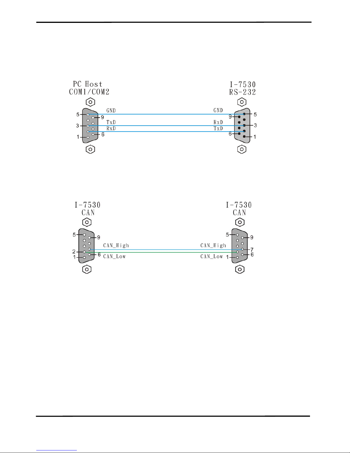
2. Hardware Installation
Users need to make a hardware connection between the CAN
devices before the application. The details of this are illustrated below:
Step1: Set-up the 120Ω terminator resistor of module A and B.
Before you continue, if you have changed the settings from default
then it is necessary to open the cover for each I-7530 and re-configure
their JP3 jumpers to enable them again, as shown in below figure.
However if the I-7530’s still have their default settings then it is not
necessary to open and reset them because the default configuration is
enabled.
(fg
Enable (default),
(Activate)
Step2: Power connection for the I-7530 A and B
Connect the (R)+Vs and (B)GND pins of the I-7530 module to the DC
power supply (10~30VDC).
0VDC
+24VDC
I-7530 RS-232/CAN Converter Quick Start User Guide (Version 2.0, Sep/2007, I-7530) ------ 3
Step3: RS-232 connection
Connect the RS-232 ports of the I-7530 A and I-7530 B to the RS-232
COM1 and COM2 on the PC respectively.
Step4: CAN bus connection
Connect the CAN ports of these two I-7530 modules using the
following structure.
3. The I-7530 Parameters Configuration
Before starting the I-7530 converter tests, users need to configure the
RS-232 & CAN parameters via the I-7530 Utility tool. The details of this
procedure are shown below.
Step1: Turn off the DC power connected with these two I-7530 modules.
Step2: Set the Init/Normal switches on the back of the I-7530 A to the
“Init” position. Then, turn on the DC power. The ON LED of the I7530 A will be flash approximately once per second. That means
that the I-7530 is in the configuration mode.
Step3: Run the I-7530 Utility. The “I7530.exe” is located in the

I-7530 RS-232/CAN Converter Quick Start User Guide (Version 2.0, Sep/2007, I-7530) ------ 4
can_cd\can\converter\i-7530\ folder on the companion CD-ROM or
can be downloaded from the web site:
http://www.icpdas.com/download/can/index.htm
Step4: Click the “Connect” icon to select the PC COM port and Baud rate,
which are used to connect with the I-7530 A. The default setting of
the PC COM port is configured at 115200bps, 8 Data Bits, 1 Stop
bit, no parity and no Checksum automatically. The steps are
shown in the following figure.
①
③
②
Step5: Click the “Ok” button. If this process is successful, the I-7530 Utility
shows the I-7530 A communication information as below.

I-7530 RS-232/CAN Converter Quick Start User Guide (Version 2.0, Sep/2007, I-7530) ------ 5
Step6: In order to match the RS-232 parameters on the PC COM port,
please configure the RS-232 parameters of the I-7530 A as follows:
Baud rate : 115200bps
Data bits : 8
Stop bits : 1
Parity : None
Checksum : No
Step7: Set the CAN baud rate of the I-7530 A. Here, use 125K bps for
CAN baud, and uncheck the pair connection (For more information
about pair connection, please refer to user manual section 3.4).
Step8: Click the “Setting” button to save these CAN/RS-232 parameters
into the EEPROM of the I-7530 A.
Step9: Repeat Steps 1 to 8 to configure the I-7530 B converter with the
same parameter settings as the I-7530 A.

I-7530 RS-232/CAN Converter Quick Start User Guide (Version 2.0, Sep/2007, I-7530) ------ 6
4. Testing the I-7530s by using the I-7530 Utility
Step1: Turn off the DC power connected with these two I-7530 modules.
Step2: Set the Init/Normal switches on the back of the I-7530 A and I-
7530 B to the “Normal” position. Then, turn on the DC power. The
ON LED of the I-7530 A and B will always be turned on. It means
these two I-7530 converters are working in the operation mode.
Step3: Run the I-7530 Utility, I7530.exe, two times. Then duplicate I-7530
windows will be displayed on the screen. One is named as Utility A
and the other is called Utility B.
Step4: Select the “Test” tab and click the “Connect” icon on the tool bar of
Utility A and Utility B to configure the RS-232 COM1 and the RS232 COM2 on the PC. The COM1 and COM2 ports on the PC will
be used for connecting with the I-7530 A and B converters,
respectively.
Step5: After selecting the necessary Com port and baud rate, click the
“Ok” button on Utility A and B, respectively. Then, Utility A is
shown in the below figure and Utility B will be similar to Utility A.
Step8: Check the “Use CAN Message” checkbox and input the value to
the “CAN Message” frame on Utility A. Click the “Send” button.
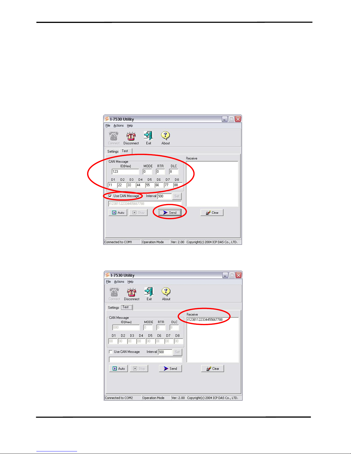
I-7530 RS-232/CAN Converter Quick Start User Guide (Version 2.0, Sep/2007, I-7530) ------ 7
Then, the Utility will automatically transfer these CAN messages to
the RS-232 command string with ASCII 0x0d, and send it out
through the PC RS-232 COM1 port. After the I-7530 A receives
this command. It will transfer the RS-232 message to the CAN
message. So, the I-7530 B will receive the CAN message
transmitted from I-7530 A. Then, convert this CAN message to the
RS-232 message and send it out to the COM2 port on the PC.
Detailed steps of this are shown in the following figure.
Utility A
④③②
①
Utility B
 Loading...