

ICPDAS I-7188XB User Manual

I-7188XB Series User’s Manual
Warranty
All products manufactured by ICP DAS are under warranty regarding
defective materials for a period of one year, beginning from the date of
delivery to the original purchaser.
Warning
ICP DAS assumes no liability for any damage resulting from the use of
this product. ICP DAS reserves the right to change this manual at any
time without notice. The information furnished by ICP DAS is believed to
be accurate and reliable. However, no responsibility is assumed by ICP
DAS for its use, not for any infringements of patents or other rights of
third parties resulting from its use.
Copyright
Copyright©2007 by ICP DAS Co., Ltd. All rights are reserved.
Trademark
The names used for identification only may be registered trademarks of
their respective companies.
I-7188XB Series User’s Manual(Ver.1.0, Apr/2007, 7MH-020-10 ) ---
1

Table of Contents
1. Introduction..................................................................................................4
1.1 FEATURES.....................................................................................................................5
1.2 SPECIFICATIONS..........................................................................................................6
1.3 Software and Document information ..............................................................................7
1.4 Hardware Information.....................................................................................................9
1.4.1 Schematics and Dimensions of the I-7188XB(D) ....................................................9
1.4.2 Pin Assignment......................................................................................................10
1.4.3 Mounting the I-7188XB(D).....................................................................................12
1.4.4 Block Diagram.......................................................................................................13
1.4.5 Wiring Diagrams for Application............................................................................14
1.4.6 DI/DO wire connection ..........................................................................................18
1.4.7 Mounting the I/O Expansion Bus...........................................................................19
2. Quick Start.................................................................................................. 20
2.1 Software Installation.....................................................................................................20
2.2 Connect the Download Cable to the Host PC...............................................................21
2.3 Downloading Programs to the I-7188XB(D) .................................................................23
2.4 MiniOS7 Upgrade.........................................................................................................27
3. Writing Your First Program....................................................................... 29
3.1 Libraries........................................................................................................................29
3.2 Compiler and Linker .....................................................................................................30
3.3 The Detailed Steps for Programming............................................................................31
3.3.1 Download Turbo C++ version 1.01........................................................................31
3.3.2 Install Turbo C++ version 1.01...............................................................................33
3.3.3 Set the environment variables of the system.........................................................36
3.3.4 Build and Execute the Program.............................................................................38
4. Operating Principles.................................................................................. 47
4.1 System Mapping...........................................................................................................47
4.2 Debugging custom Programs using COM1..................................................................48
4.3 Using the Download Port as a COM Port.....................................................................50
4.4 Functions and Demo Programs List .............................................................................51
4.5 COM Port Comparison.................................................................................................54
4.6 Using the COM Ports....................................................................................................55
4.6.1 To print from the COM port....................................................................................56
4.6.2 To Use COM1/COM2 for an RS-485 Application...................................................57
4.6.3 To Send a Command to an I-7000 module............................................................57
4.7 Using the Red LED and 7-SEG LED Display ...............................................................60
4.8 Accessing the I-7188XB(D) Memory ............................................................................61
4.8.1 Using Flash Memory .............................................................................................61
4.8.2 Using RTC and NVRAM........................................................................................62
4.8.3 Using EEPROM.....................................................................................................63
4.9 Using the Watchdog T imer...........................................................................................65
4.10 Using the Timer Function..............................................................................................67
4.11 Using Digital Input and Digital output............................................................................68
4.12 Using the I/O Expansion Bus........................................................................................70
4.12.1 Definition of an I/O Expansion Bus........................................................................70
4.12.2 I/O Expansion Boards............................................................................................73
5. Applications ...............................................................................................75
5.1 Embedded Controllers..................................................................................................75
I-7188XB Series User’s Manual(Ver.1.0, Apr/2007, 7MH-020-10 ) ---
2

5.2 Local Real Time Controller (RTC).................................................................................76
5.3 Remote Local Controller...............................................................................................77
5.4 PLC I/O Expansion Application.....................................................................................78
5.5 Radio Modem Application.............................................................................................80
5.6 An Application Using 4 COM Ports (1)..........................................................................82
5.7 An Application Using 4 COM Ports (2)..........................................................................83
Appendix A: What is MiniOS7...........................................................................84
Appendix B: MiniOS7 Utility and 7188XW.......................................................87
MiniOS7 Utility.....................................................................................................................87
7188XW...............................................................................................................................89
Appendix C: Comparison Table........................................................................98
Appendix D: Library Function List...................................................................99
Appendix E: Compiling and linking ...............................................................136
Using the TC Compiler ......................................................................................................136
Using the BC++ Compiler..................................................................................................139
Using MSC Compiler.........................................................................................................145
Using MSVC++ Compiler...................................................................................................147
Appendix F: Glossary......................................................................................152
I-7188XB Series User’s Manual(Ver.1.0, Apr/2007, 7MH-020-10 ) ---
3
1. Introduction
The I-7188XB(D) is a series of expandable embedded controllers
designed for industry applications and can be used to replace PC or
PLC devices in harsh environments. The I-7188XB(D) also has support
for an I/O expansion bus, which can be used to implement various I/O
functions, such as D/I, D/O, A/D, D/A, UART, Flash memory, battery
backup SRAM
, AsicKey and other I/O functions. Most types of I/O
function can be implemented using this bus. ICP DAS
offers more than
20
types of I/O Expansion Board for the I-7188XB(D), which can be
used to expand the features of the controller.
Depending on the type of
embedded firmware programs that are being developed, and which I/O
Expansion Board, the I-7188XB(D) can be used as a single versatile
controller.
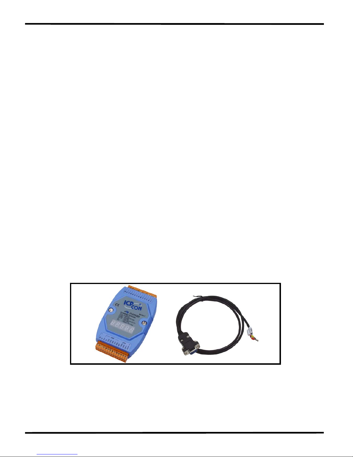
Package List
In addition to this manual, the shipping package includes the following
items:
One I-7188XB(D) module
One download cable (CA0910)
One companion CD containing software drivers and digital
versions of the user manuals
One copy of the release notes
CA0910
Note: If any of these items are missing or damaged, please contact
your local distributors for more information. We recommend that you
save the shipping materials and cartons in case you want to ship the
product in the future.
I-7188XB Series User’s Manual(Ver.1.0, Apr/2007, 7MH-020-10 ) ---
4

1.1 FEATURES
Embedded 80188 CPU, 40M or compatible
Built-in RTC, NVRAM and EEPROM
2 Built-in COM ports: COM1 and COM2
64-bit internal hardware-unique serial number
COM driver supports both interrupt and 1K QUEUE input/output
buffer
Support for I/O expansion bus interface (Only one expansion
board can be added)
One Digital Input Channel
One Open-collector output Channel
Built-in self-tuner ASIC controller on the RS-485 port
Optional 7-segment LED display
Built-in MiniOS7 by ICP DAS
Program download port: COM1
I-7188XB Series User’s Manual(Ver.1.0, Apr/2007, 7MH-020-10 ) ---
5
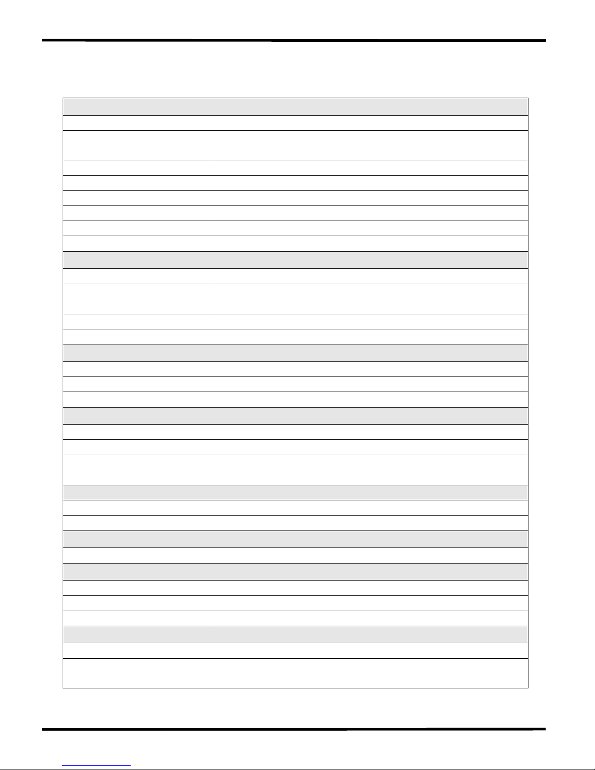
1.2 SPECIFICATIONS
CPU module
CPU 80188 CPU, 40MHz or compatible
SRAM
256K bytes for I-7188XB
512K bytes for I-7188XB/512
Flash 512K bytes
EEPROM 2K bytes
NVRAM 31 bytes
RTC (Real Time Clock) Yes
Hardware Serial Number Yes
Build-in Watchdog Timer Yes
Communication Interface
COM 1 RS-232/RS-485 (Default is RS-232)
COM 2 RS-485 (can be upgraded to 3000V isolated for OEM)
COM 3 No
COM 4 No
Ethernet Port No
Digital Input
Input Channels 1
On Voltage Level +1V/DC Max. (Connect to GND)
Off Voltage Level +3.5V/DC to +30V/DC Max.
Digital Output
Output Channels 1
Output T ype Open-collector
Max Load Current 100mA
Load Voltage +30V/DC Max.
LED Display
1 LED as Power/Communication Indicator
5-digit 7-segment LED (for I-7188XBD only)
Dimensions
123mm x 72mm x 33mm
Operating Environment
Operating temperature -25°C to +75°C
Storage Temperature -40°C to +80°C
Humidity 0 to 90%
Power
Power requirements 10 to 30V/DC (non-regulated)
Power consumption
2.0W for I-7188XB
3.0W for I-7188XBD
I-7188XB Series User’s Manual(Ver.1.0, Apr/2007, 7MH-020-10 ) ---
6
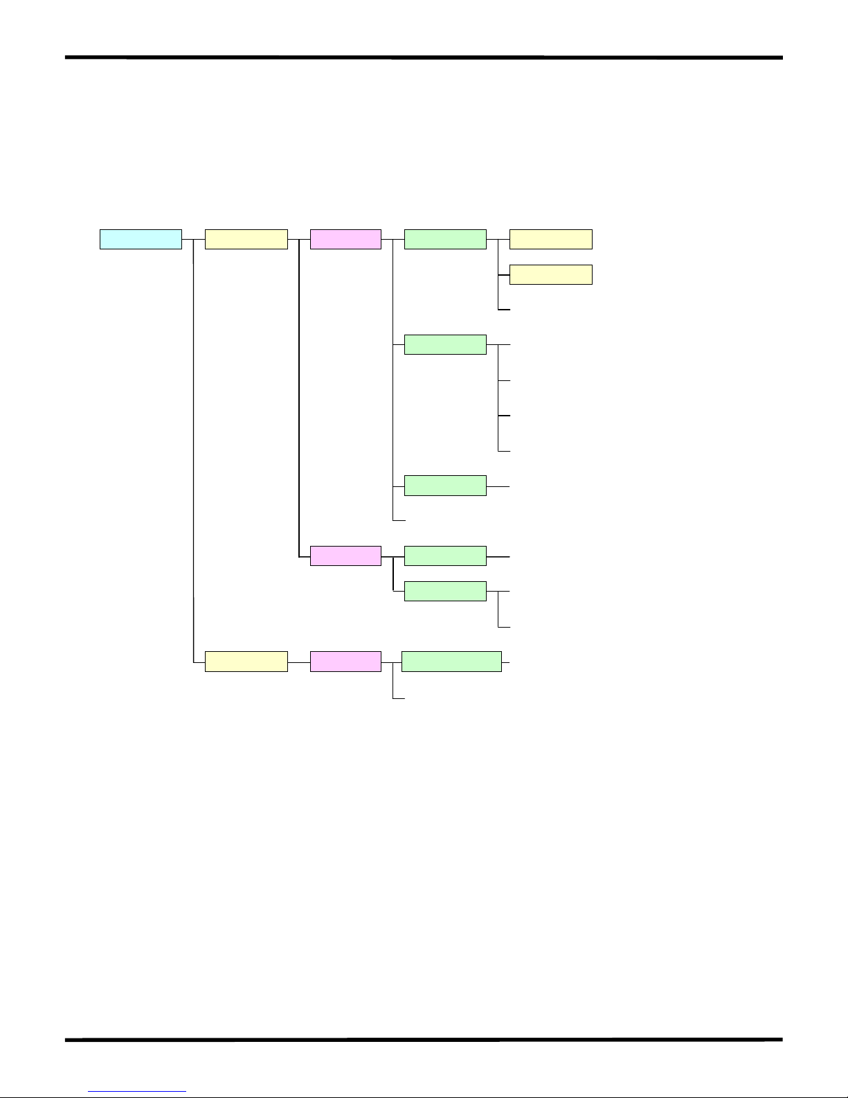
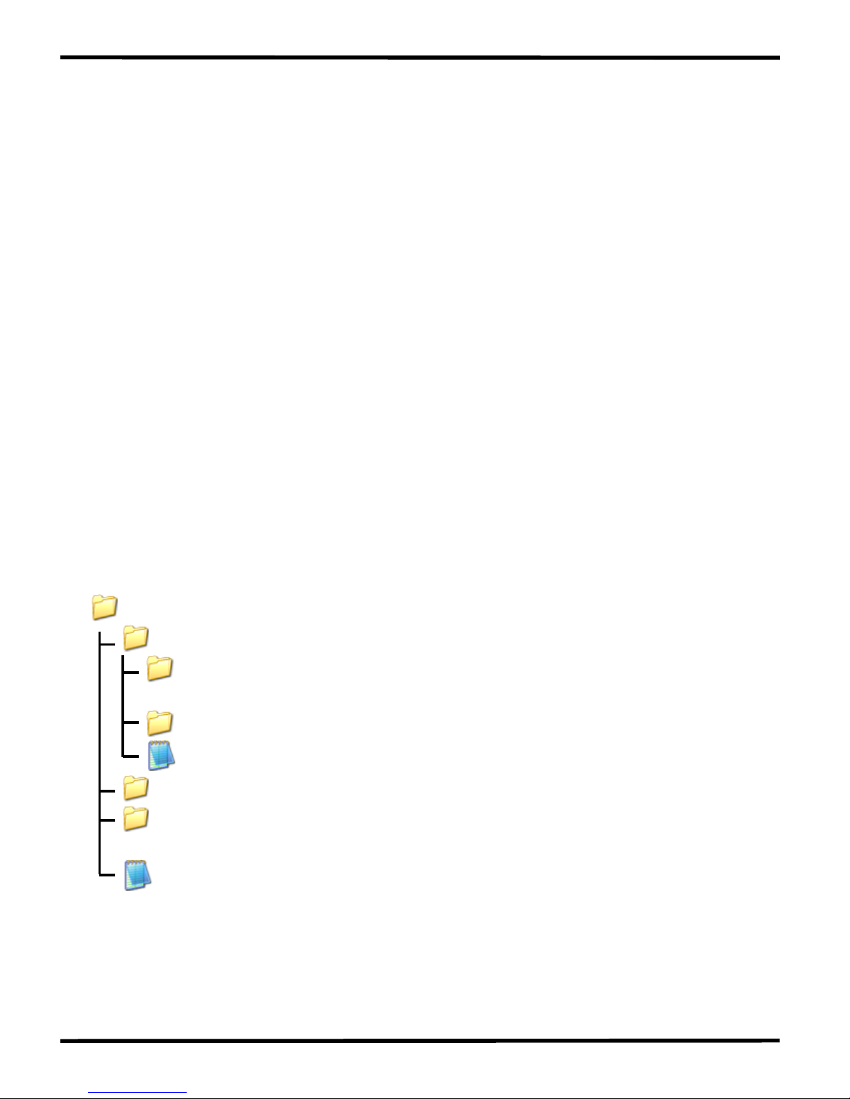
1.3 Software and Document information
The location of all documents and software related to the I-7188XB(D)
on the companion CD are shown in the following directory tree. The
relevant file can quickly be located by referring to the tree.
CD:\Napdos 7188XABC 7188XB Demo BC_TC
MSC
7188XB_DemoList.htm
7188XB.pdf
Document
IO_Expansion_bus_docum
MiniOS7_document.html
Program_Develop_document.html
ent.html
OS_image
7188xb_cr_20060614.img
Xboard Demo
Document
Readme.html
iobus_e.pdf
X702X703.pdf
MiniOS7 Utility
MiniOS7_utility
minios7_utility_V311.exe
Readme.html
7188xw.exe
The documents and software listed above can also be obtained from the
ICP DAS website: http://f tp.icpdas.com/pub/cd/8000cd/napdos. The
folder location of all documents and software on the website is identical
to the companion CD.
The iobus_e.pdf file that is provided in the
CD:\Napdos\7188XABC\Xboard\Document\ folder and the “I/O
Expansion Bus for 7188X/7188E User’s Manual” contain the same
content, so the user can refer to either document for more details
related to the I-7188XB(D) I/O expansion bus.
I-7188XB Series User’s Manual(Ver.1.0, Apr/2007, 7MH-020-10 ) ---
7

Before continuing, it is recommended that you read the Readme.html,
which can be found in the CD:\Napdos\7188XABC\7188XB\. The latest
information available prior to shipping will be contained in this file.
I-7188XB Series User’s Manual(Ver.1.0, Apr/2007, 7MH-020-10 ) ---
8

1.4 Hardware Information
1.4.1 Schematics and Dimensions of the I-7188XB(D)
Top View
Rear View Side View
Unit: mm
DIN-RAIL MOUNTING
BRACKET
Front View
Bottom View
I-7188XB Series User’s Manual(Ver.1.0, Apr/2007, 7MH-020-10 ) ---
9
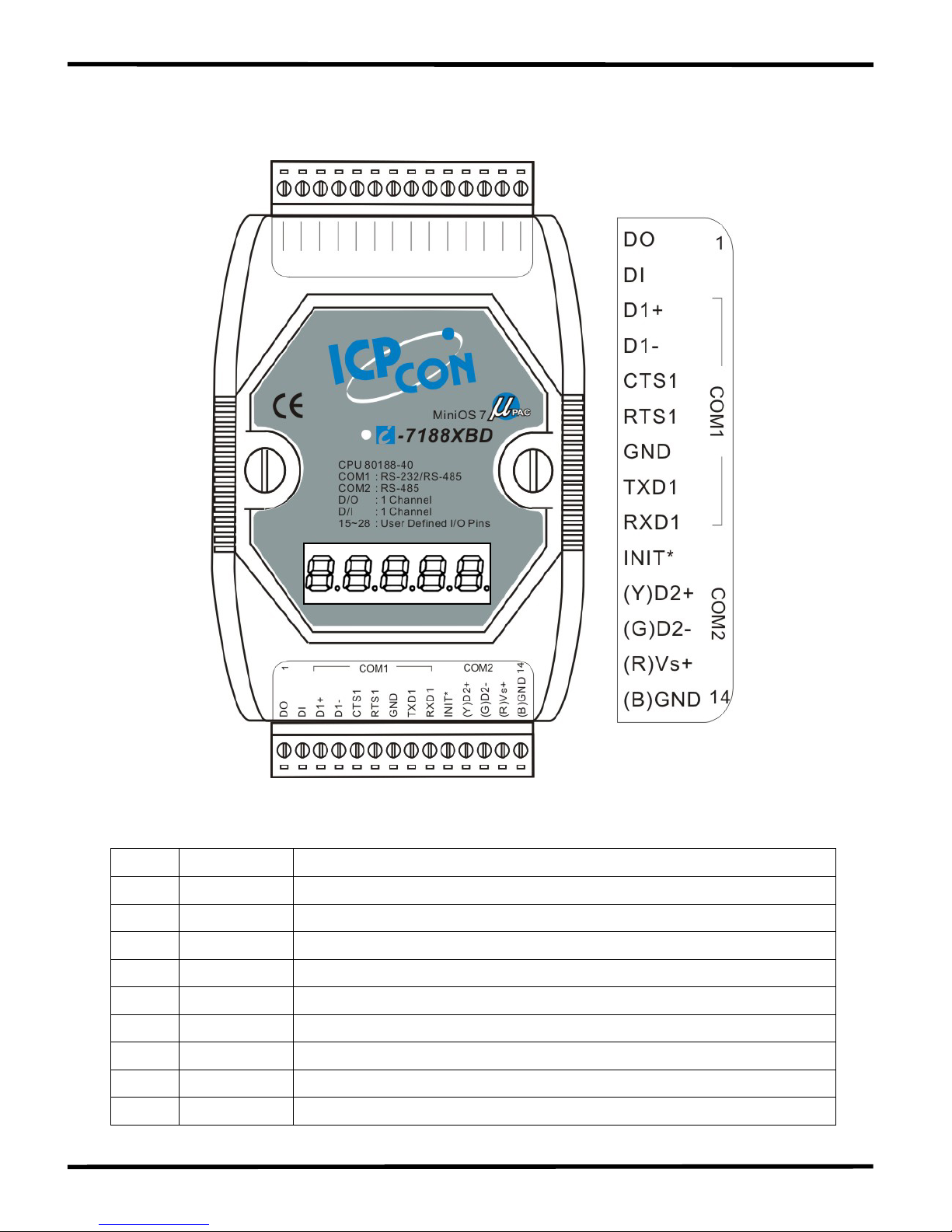
1.4.2 Pin Assignment
The pin assignment of 14-pin screw terminal block is as follows:
Pin Name Description
1 DO Digital output, 100mA, 30V Max.
2 DI Digital input, 3.5V ~ 30V
3 D1+ DATA+ pin for COM1 (RS-485)
4 D1- DATA- pin for COM1 (RS-485)
5 CTS1 CTS pin for COM1 (RS-232)
6 RTS1 RTS pin for COM1 (RS-232)
7 GND GND pin for COM1 (RS-232)
8 TXD1 TXD pin for COM1 (RS-232)
9 RXD1 RXD pin for COM1 (RS-232)
I-7188XB Series User’s Manual(Ver.1.0, Apr/2007, 7MH-020-10 ) ---
10

10 INIT* Initial pin
11 D2+ DATA+ pin for COM2 (RS-485)
12 D2- DATA- pin for COM2 (RS-485)
13 +VS V+ of power supply (+10 to +30V/DC, unregulated)
14 GND GND for the power supply
Note: The COM1 can be used as either an RS-232 or RS-485 port. It is
not recommended to use both RS-232 and RS-485 at the same time.
The pin assignment of top 14-pin screw terminal block is as follows:
Pin Name Description
15 Pin 15 User defined pin 15
16 Pin 16 User defined pin 16
17 Pin 17 User defined pin 17
18 Pin 18 User defined pin 18
19 Pin 19 User defined pin 19
20 Pin 20 User defined pin 20
21 Pin 21 User defined pin 21
22 Pin 22 User defined pin 22
23 Pin 23 User defined pin 23
24 Pin 24 User defined pin 24
25 Pin 25 User defined pin 25
26 Pin 26 User defined pin 26
27 Pin 27 User defined pin 27
28 Pin 28 User defined pin 28
I-7188XB Series User’s Manual(Ver.1.0, Apr/2007, 7MH-020-10 ) ---
11
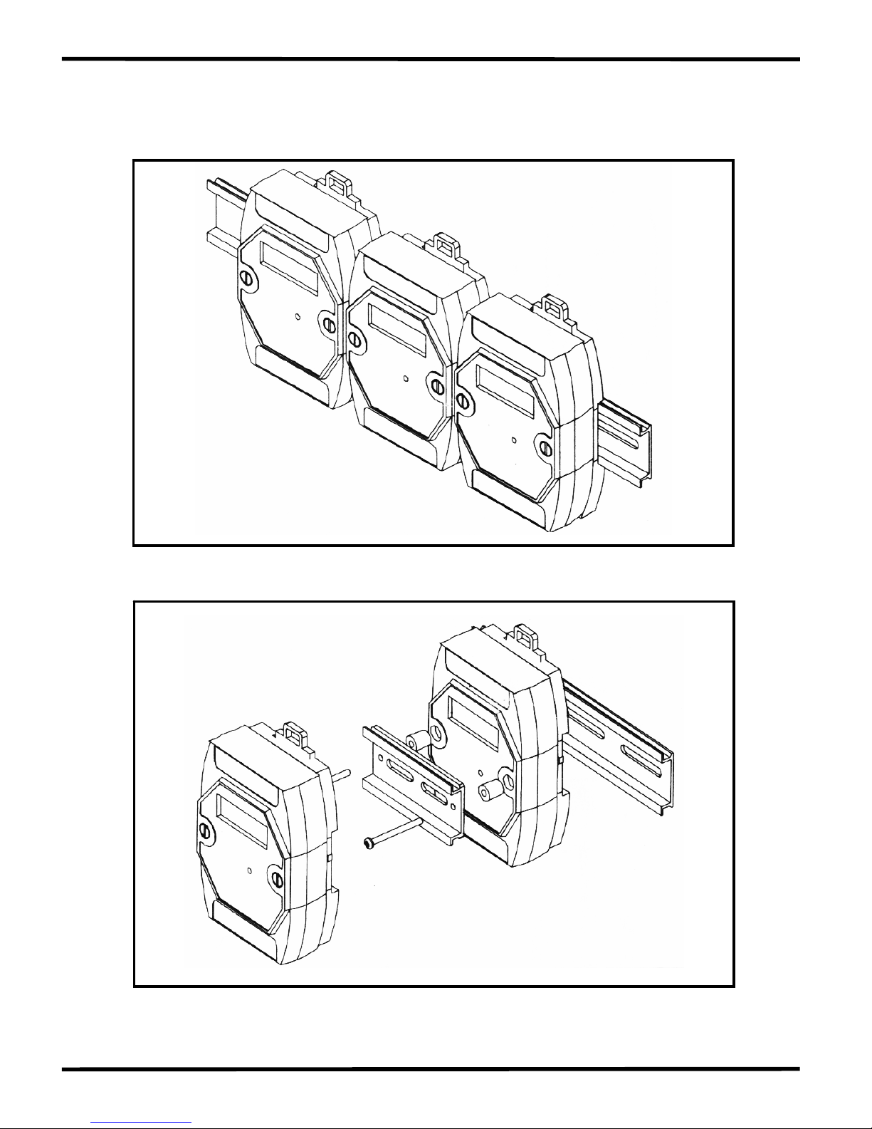
1.4.3 Mounting the I-7188XB(D)
1. Din-Rail Mounting
2. Stack Mounting
I-7188XB Series User’s Manual(Ver.1.0, Apr/2007, 7MH-020-10 ) ---
12
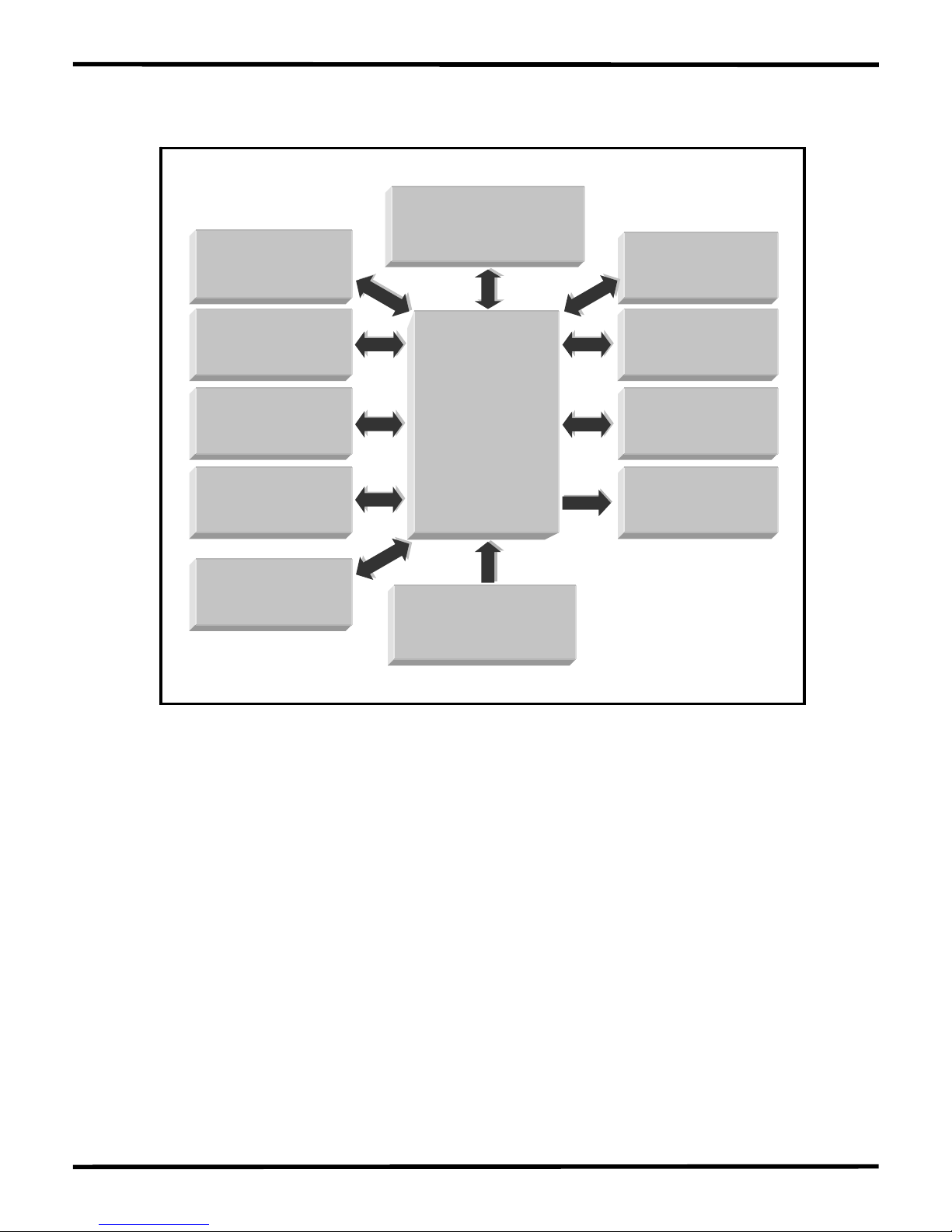
1.4.4 Block Diagram
80188-40 CPU
or compatible
RTC
&
NVRAM
COM2
RS-485
DI: 1 Channel
3.5V to 30V
DO: 1 Channel
100mA, 30V
COM1
RS-232/RS-485
EEPROM
(2K)
5-Digit LED
(Optional)
SRAM=256K
Flash Memory=512K
Watchdog
Circuit
+10V to +30V
Power Converter
User defined Pin
14 pins
I-7188XB Series User’s Manual(Ver.1.0, Apr/2007, 7MH-020-10 ) ---
13
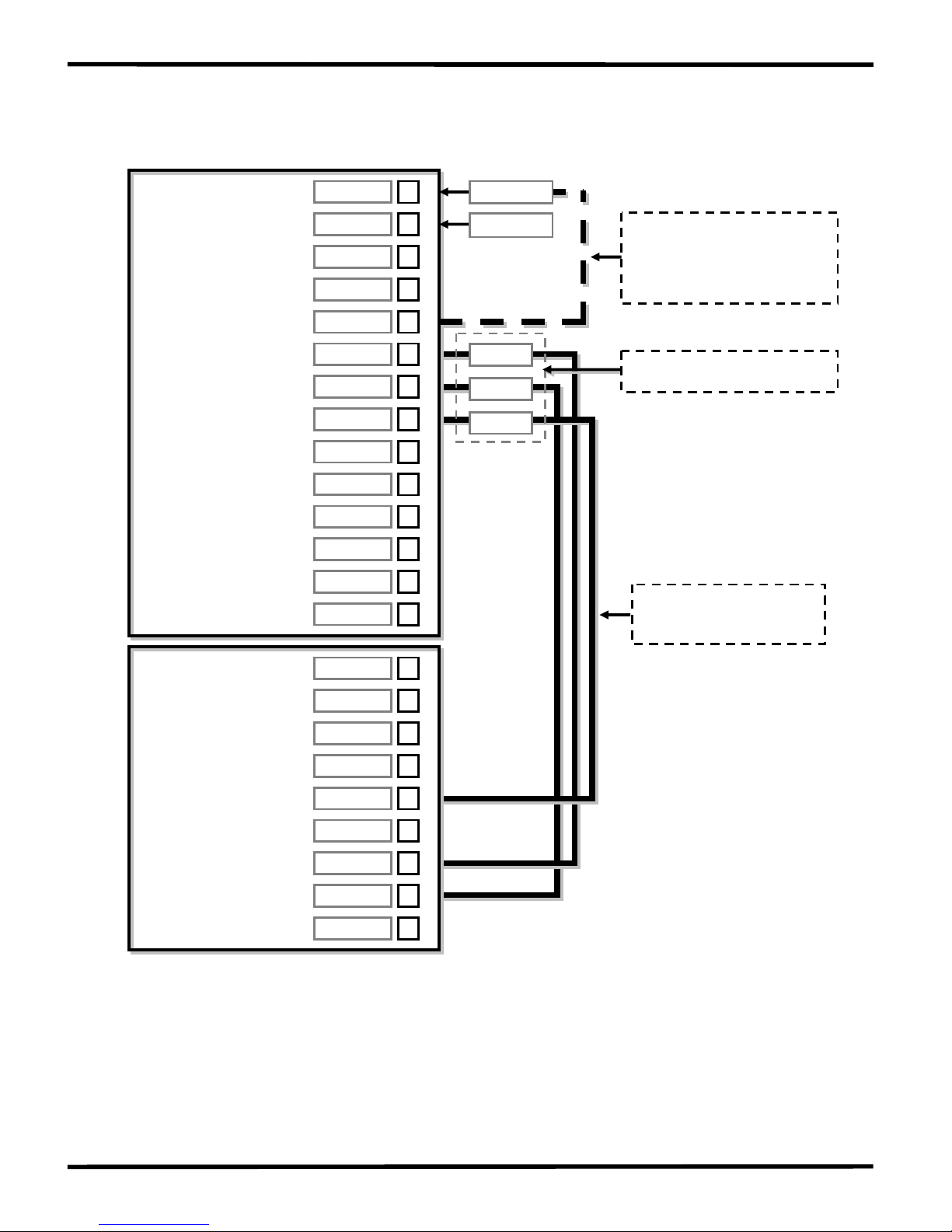
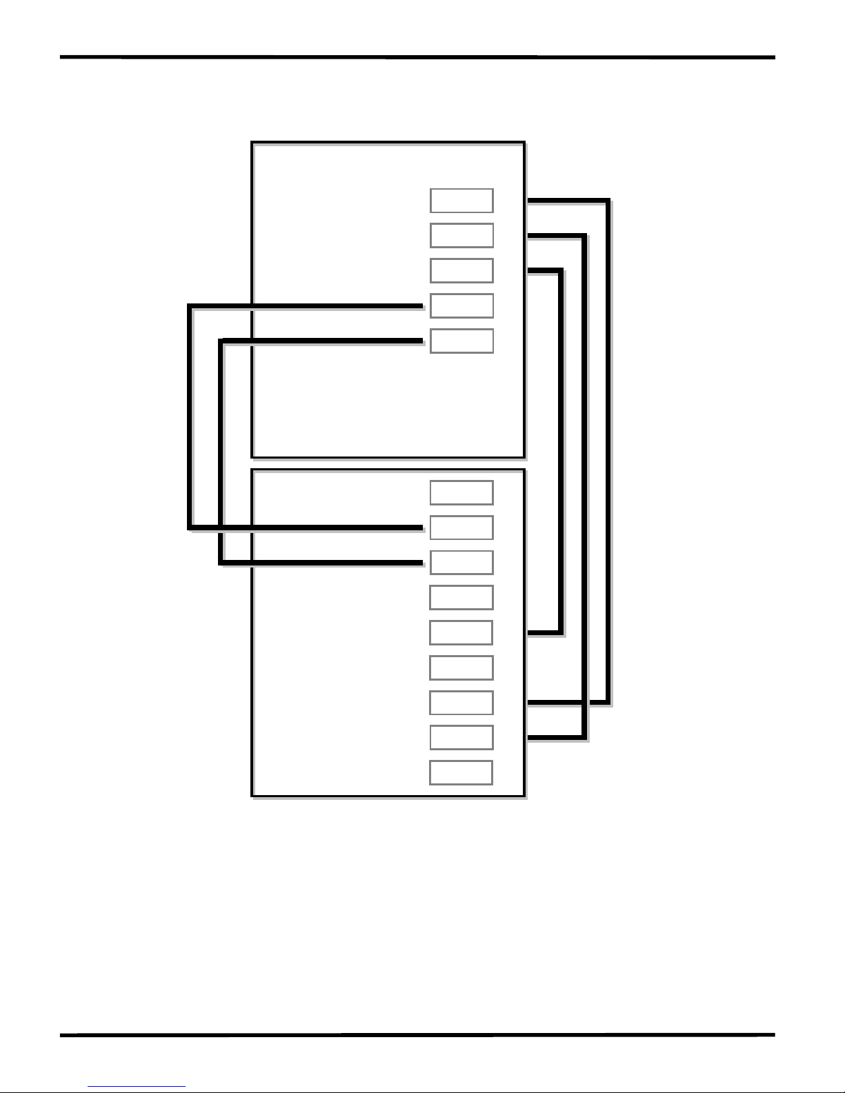
1.4.5 Wiring Diagrams for Application
Program download
1DCD
7188XB/7188XBD
COM Port of the PC
RI
CTS
RTS
DSR
GND
DTR
TXD
D2+
Init*
RXD1
+VS
D2-
TXD1
GND
GND
RTS1
14
13
12
11
10
9
8
7
6
9
8
7
6
5
4
3
D1+
DI
DO
CTS1
D1- 54
3
2
1
Ext.GND
Ext. 24V
Program download
wiring connection
Connect the INIT* pin
to GND to disable
autoexec.bat
GND
RXD
TXD
Wiring label for CA0910
2RXD
Note: There are 3 wires in the download cable:
Connect wire-1, labelled RX, to pin-9 of the I-7188XB(D)
Connect wire-2, labelled TX, to pin-8 of the I-7188XB(D)
Connect wire-3, labelled GND, to pin-7 of the I-7188XB(D)
Connect the DB-9 of the download cable to the COM Port of PC
I-7188XB Series User’s Manual(Ver.1.0, Apr/2007, 7MH-020-10 ) ---
14
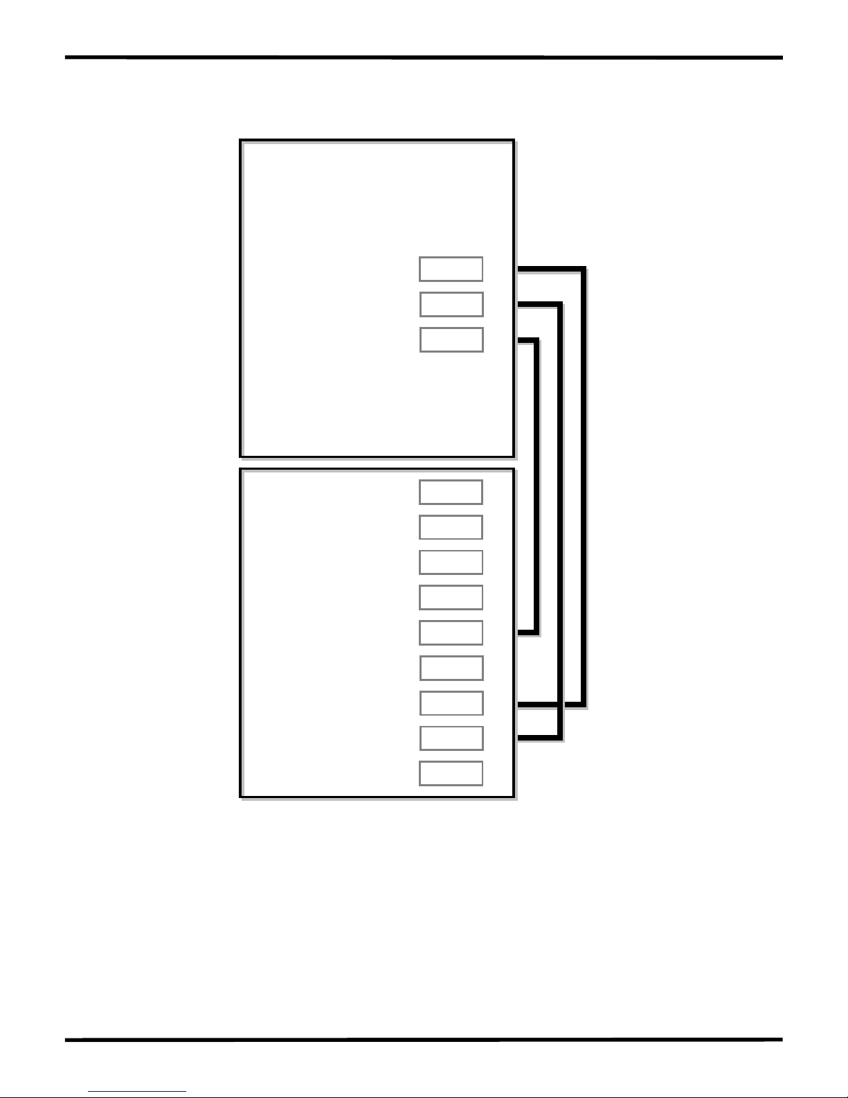
Using a 3-wire RS-232 Port
RI
CTS
RTS
DSR
GND
DTR
TXD
RXD
DCD
RS-232 Device
RXD
TXD
GND
7188XB/7188XBD
COM1
Note: There are 3 wires as follows:
Connect the RXD to the TXD of the RS-232 device
Connect the TXD to the RXD of the RS-232 device
Connect the GND to the GND of the RS-232 device
I-7188XB Series User’s Manual(Ver.1.0, Apr/2007, 7MH-020-10 ) ---
15
Using a 5-wire RS-232 Port
RI
CTS
RTS
DSR
GND
DTR
TXD
RXD
DCD
RS-232 Device
GND
RTS
CTS
7188XB/7188XBD
RXD
TXD
COM1
Note: There are 5 wires as follows:
Connect the RXD to the TXD of the RS-232 device
Connect the TXD to the RXD of the RS-232 device
Connect the RTS to the CTS of the RS-232 device
Connect the CTS to the RTS of the RS-232 device
Connect the GND to the GND of the RS-232 device
I-7188XB Series User’s Manual(Ver.1.0, Apr/2007, 7MH-020-10 ) ---
16
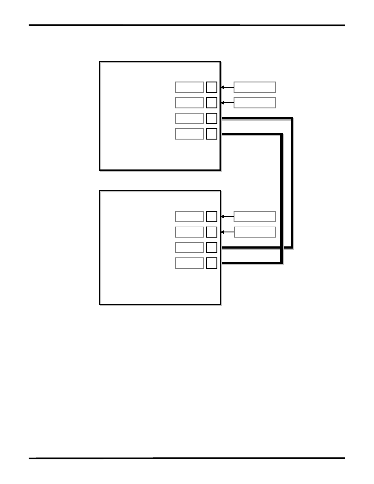
Using the RS-485 Port
GND
+VS
D2-
D2+
7000 Module
D2-
D2+
7188XB/7188XBD
GND
+VS
10
9
8
7
14
13
12
11
Ext. GND
Ext. 24V
Ext. GND
Ext. 24V
COM1/COM2
Note: The RS-485 interface can directly drive up to 256 I-7000 series
modules without the need for a repeater.
I-7188XB Series User’s Manual(Ver.1.0, Apr/2007, 7MH-020-10 ) ---
17
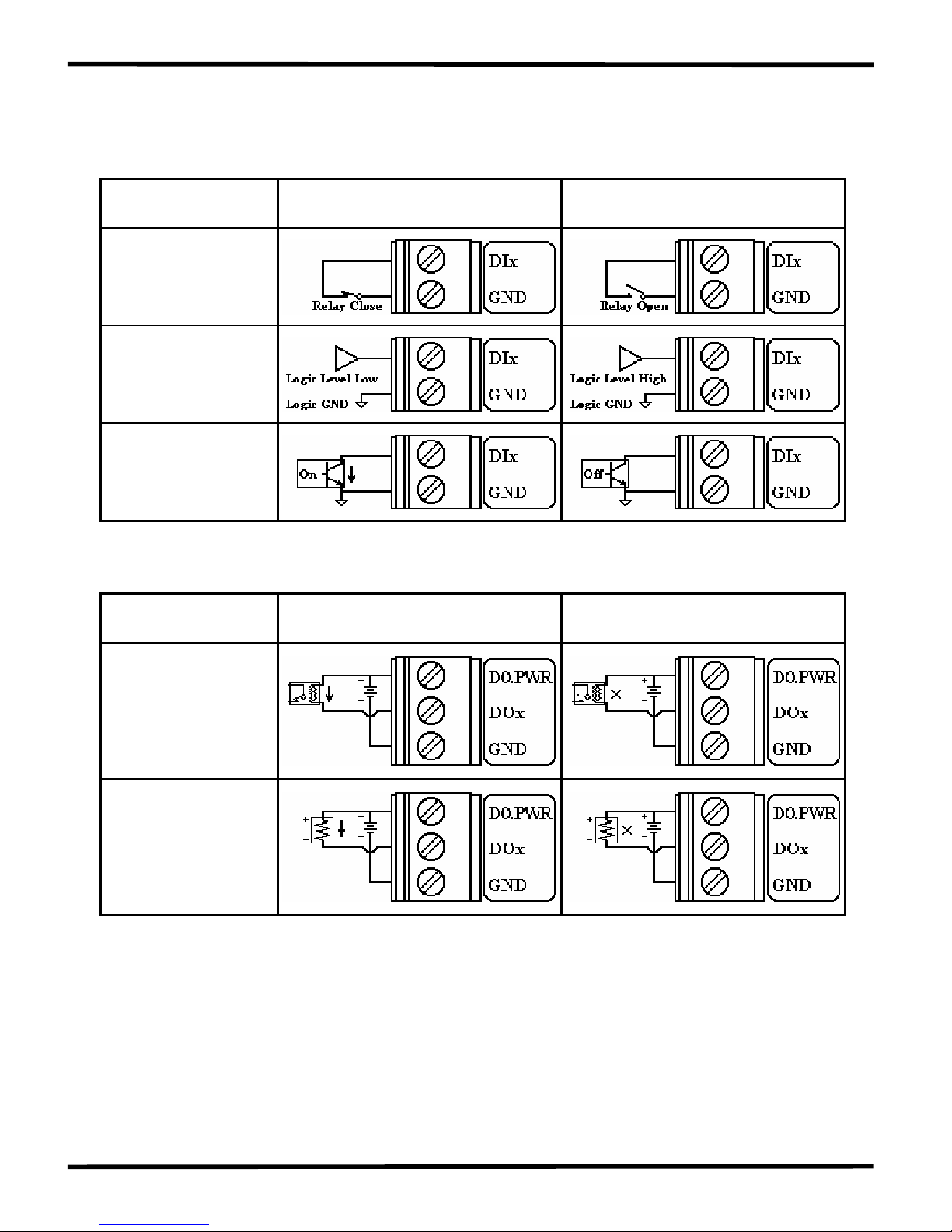
1.4.6 DI/DO wire connection
Digital Input Wire Connection
Input Type
ON State
DI value as 0
OFF State
DI value as 1
Relay Contact
TTL/CMOS Logic
Open Collector
Digital Output Wire Connection
Input Type
ON State
DO value as 1
OFF State
DO value as 0
Drive Relay
Resistance Load
I-7188XB Series User’s Manual(Ver.1.0, Apr/2007, 7MH-020-10 ) ---
18
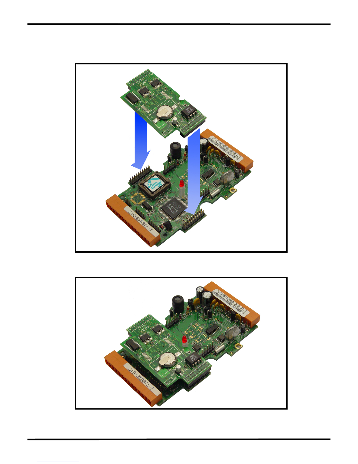
1.4.7 Mounting the I/O Expansion Bus
Before mounting:
After mounting:
I-7188XB Series User’s Manual(Ver.1.0, Apr/2007, 7MH-020-10 ) ---
19
2. Quick Start
2.1 Software Installation
Step 1: Insert the companion CD into the CD drive.
Step 2: Copy the 7188XB folder from CD:\Napdos\7188XABC\ to the
Hard Drive of the Host PC.
Step 3: Install the MiniOS7 Utility.
Locate and execute the minios7_utility_v311.exe file from
CD:\NAPDOS\MINIOS7\UTILITY\MiniOS7_utility\ folder or
http://ftp.icpdas.com/pub/cd/8000cd/napdos/minios7/utility/minios7_
utility/
Step 4: Copy the 7188xw.exe file from the CD:\Napdos\MiniOS7\utility\
folder to the PATH directory, for example C:\Windows\.
After all the software is copied to the Host PC, the content of 7188XB
folder should be as follows:
7188XB
Demo Demo programs for the I-7188XB(D)
BC_TC Demo programs for the BC++ and the TC++
compiler
MSC Demo programs for the MSC compiler
7188XB_DemoList.htm Demo list for the I-7188XB(D)
Document Documents related to the I-7188XB(D)
OS_image The MiniOS7 image file matches the demo
programs
Readme.html The detailed description about the 7188XB
folder
Note: The 7188xw .exe file is used as a bridge between the I-7188XB(D)
and the Host PC. Therefore, the 7188xw.exe file must be copied to the
“C:\Windows\” folder to allow it to be executed from any location.
I-7188XB Series User’s Manual(Ver.1.0, Apr/2007, 7MH-020-10 ) ---
20
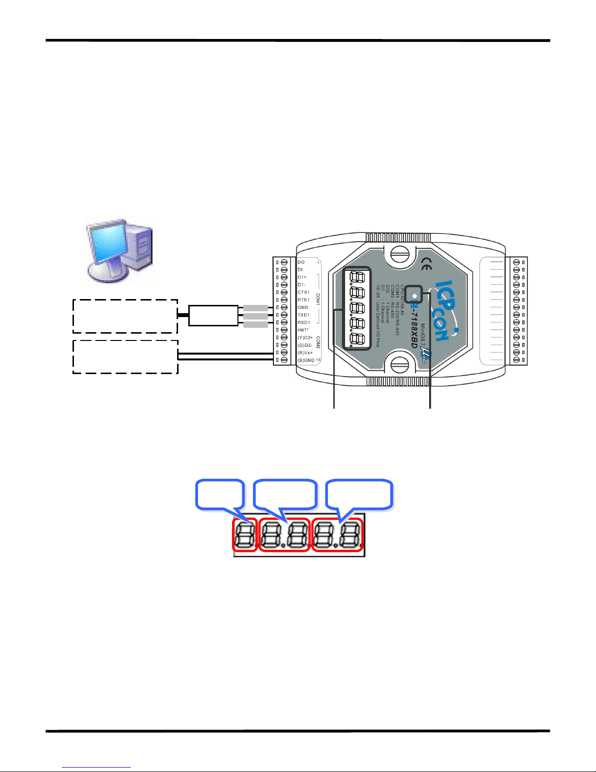
2.2 Connect the Download Cable to the Host PC
Step 1: Connect the CA0910 download cable between COM1 of the
I-7188XB(D) and the COM Port of the Host PC, as shown in the
diagram below.
Step 2: Apply power (Vs+, GND) to the I-7188XB(D). Vs+ can be in a
range from +10V to +30V DC.
CA0910
Connect to the COM
Port of Host PC
Connect to the
Power supply
Vs+
GND
GND
TXD
RXD
5-digit 7-SEG LED Red LED
Step 3: After applying the power, the 5-digits of the 7-SEG LED will
continuously show as follows.
SecondMinuteHour
If the non-display version of module is being used, please
continue to the next step.
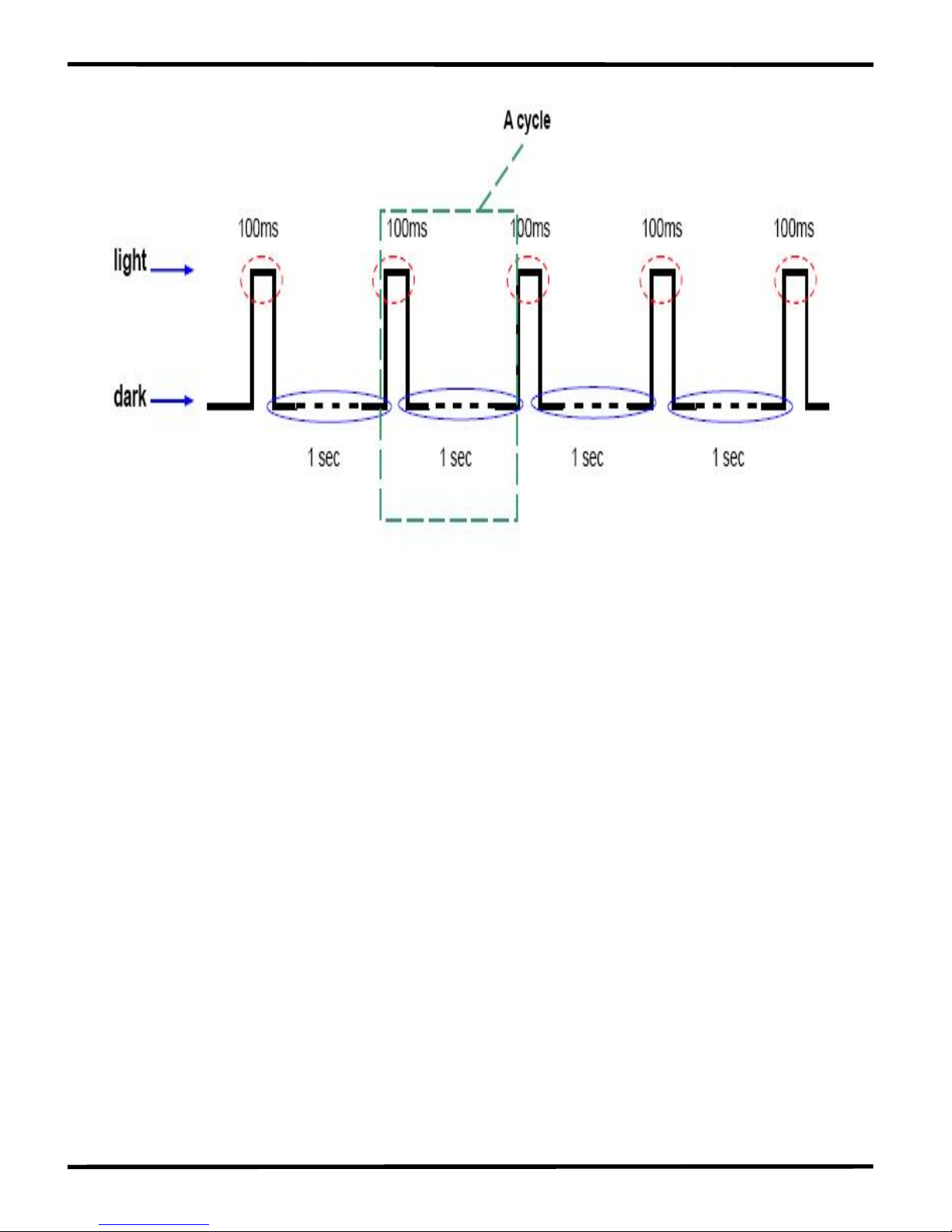
Step 4: Check that the red LED continuously blinks one times and wait
for one second to next cycle. The diagram show as follows:
I-7188XB Series User’s Manual(Ver.1.0, Apr/2007, 7MH-020-10 ) ---
21
Note: Only the display version of the module will include a 5-digit
7-SEG LED.
I-7188XB Series User’s Manual(Ver.1.0, Apr/2007, 7MH-020-10 ) ---
22
2.3 Downloading Programs to the I-7188XB(D)
Before using the MiniOS7 Utility, ensure that the download cable is
connected from the Host PC to the I-7188XB(D) and ensure that no
other programs are running on the I-7188XB(D). For details of how to
connect between the I-7188XB(D) and COM1 on the Host PC, refer to
the wiring diagram in the Sec.1.4.5---Program download.
Note: Instead of using the MiniOS7 Utility to download programs to the
I-7188XB(D), the 7188xw.exe file can also be used. Refer to Appendix
B: MiniOS7 Utility and 7188XW for details of the program download
procedure for 7188xw.exe.
The program download procedure is as follows (Refer to Sec2.1 to
install MiniOS7 Utility Ver 3.11):
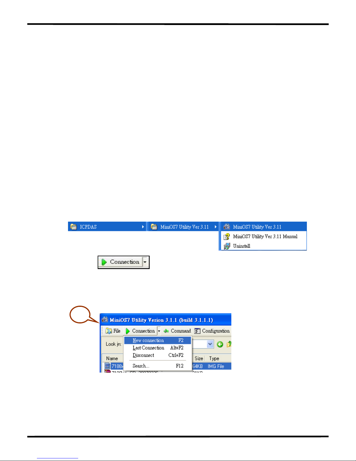
Step 1: From the Windows START menu, go to
Programs/ICPDAS/MiniOS7 Utility Ver 3.11/and locate the
MiniOS7 Utility Ver3.11.
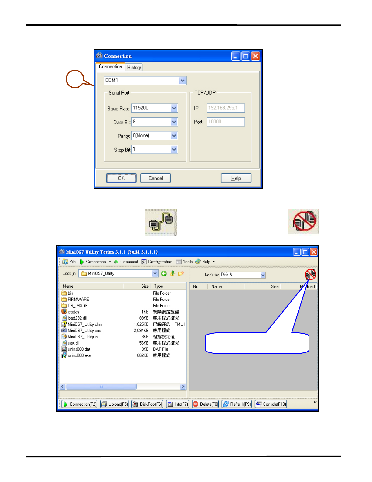
Step 2: Press and Select “New connection”. Choose the
right COM port and set other parameters. Click OK button and
the utility will search module automatically.
1
I-7188XB Series User’s Manual(Ver.1.0, Apr/2007, 7MH-020-10 ) ---
23
2
Step 3: See if the MiniOS7 Utility connects with I-7188XB. The
connected icon is . The disconnected icon is .
See here to know connection
status.
I-7188XB Series User’s Manual(Ver.1.0, Apr/2007, 7MH-020-10 ) ---
24
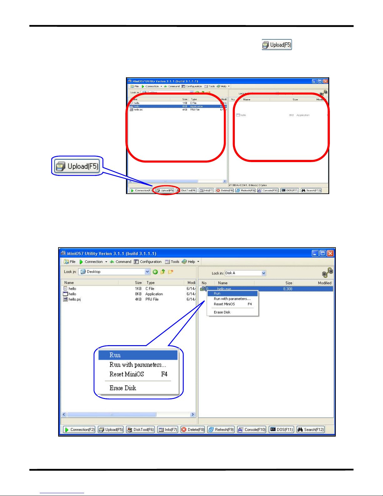
S tep 4: Select the file to load from left side and click to load file
into module or draw the file to the right side.
I-7188XB(D) file list
Host PC file list
Step 5: Select the file and then press the right mouse button. Choose
the Run and press to execute the program.
I-7188XB Series User’s Manual(Ver.1.0, Apr/2007, 7MH-020-10 ) ---
25
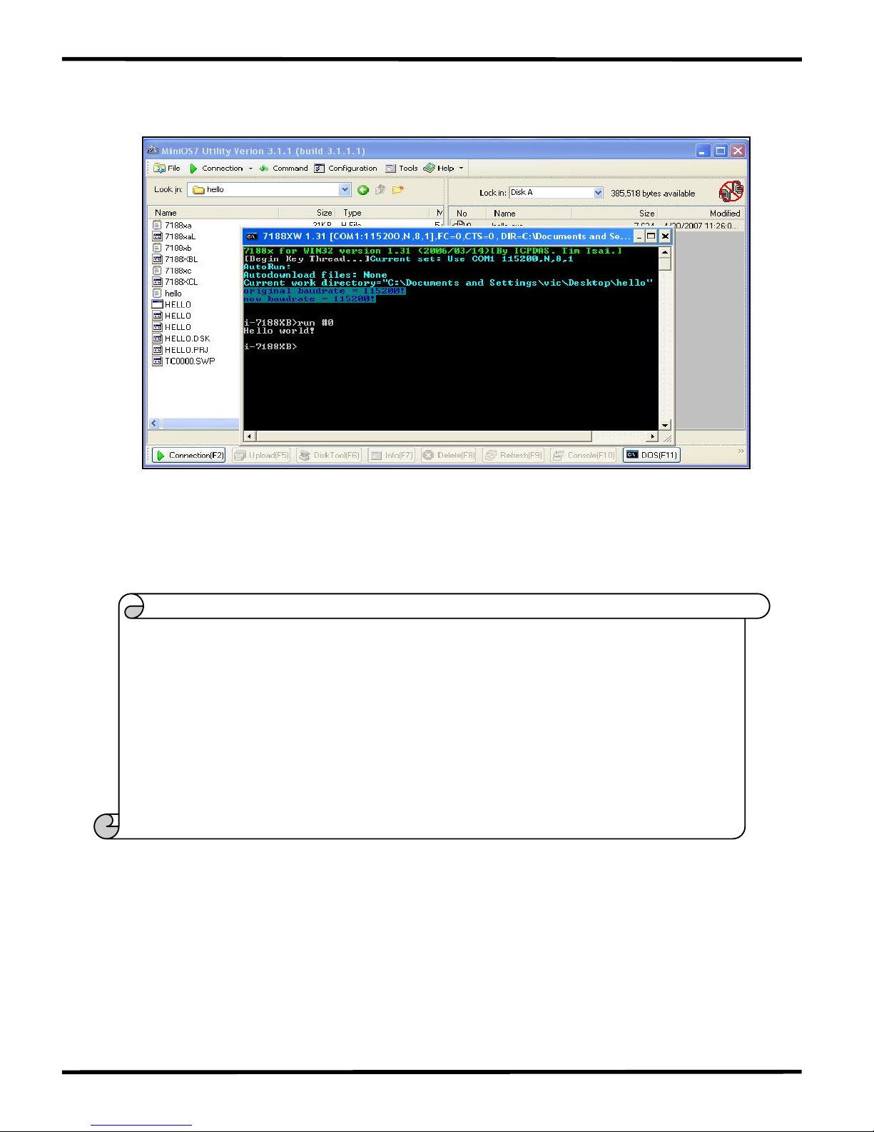
Step 6: The result of the program will be shown in 7188xw window.
NOTE: The 7188xw window has to be closed and then the download
operation (Step 4) could be done.
The content of the Hello.c file is as follows:
}
Print("Hello world!\r\n"); /* Print the message on the screen */
InitLib(); /* Initiate the 7188xb library */
#include “7188xb.h” /* Include the headers to use 7188xbl.lib
functions */
void main(void)
{
I-7188XB Series User’s Manual(Ver.1.0, Apr/2007, 7MH-020-10 ) ---
26
2.4 MiniOS7 Upgrade
ICP DAS will continue to add additional features to the MiniOS7 in the
future, so it is recommended that you periodically check the ICP DAS
website for the availability of updated versions of the MiniOS7.
Note: For a more detailed description of the MiniOS7, please refer to
Appendix A: What’s the MiniOS7.
The MiniOS7 Utility provides an easy way to upgrade MiniOS7. The
upgrade procedure is as follows:
Step 1: Get the latest version of MiniOS7 image file.
The format of the image file name is: TTYYMMDD.img
TT: TYPE of product.
YY: The year this image released
MM: The month this image released
DD: The day this image released
Note: The MiniOS7 image file contained on the companion CD can be
found in CD:\NAPDOS\MiniOS7\ directory. The latest version of
MiniOS7 can be downloaded from the ICP DAS website:
http://ftp.icpdas.com/pub/cd/8000cd/napdos/7188xabc/7188xb/os_image/
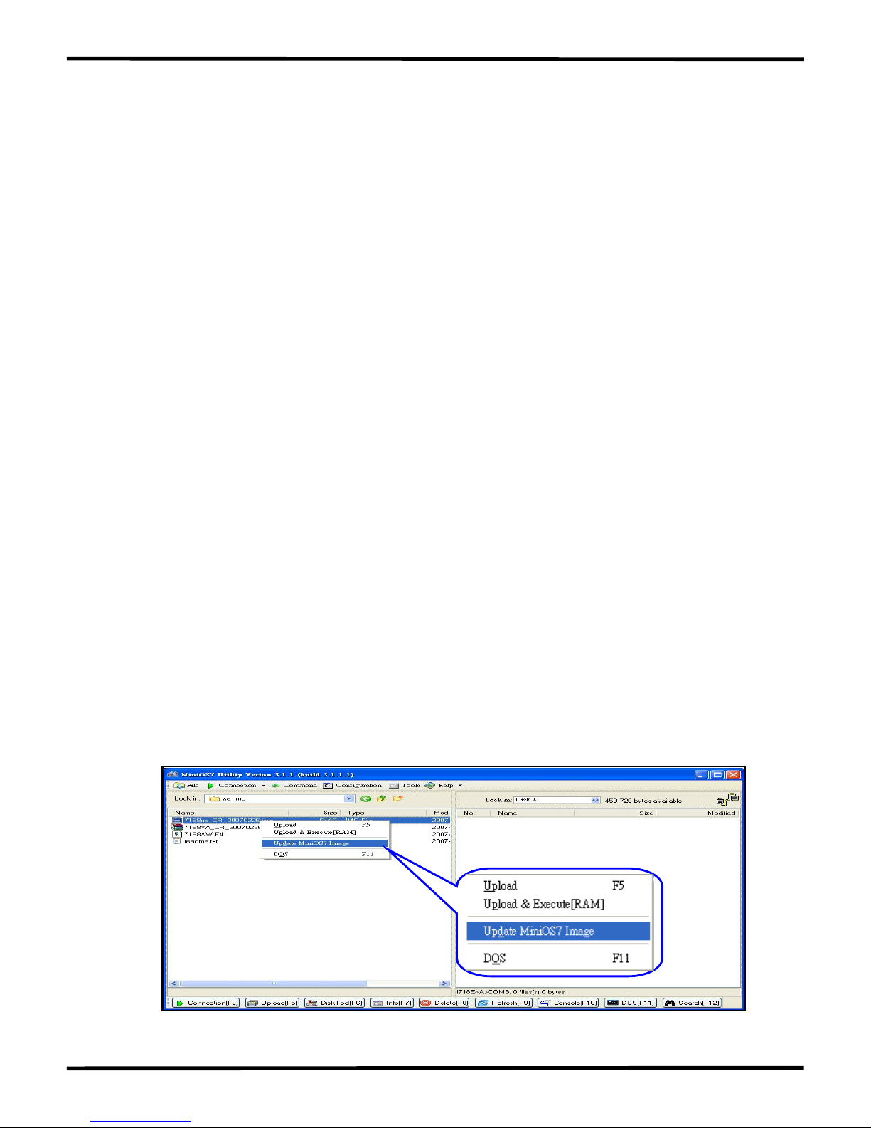
S tep 2: Execute the MiniOS7 Utility. Refer to Step2 in Sec2.3 to connect
the module. Select the MiniOS7 image file that you want to
upgrade on the left side. Click the right mouse button to choose
the “Update MiniOS7 Image”.
I-7188XB Series User’s Manual(Ver.1.0, Apr/2007, 7MH-020-10 ) ---
27
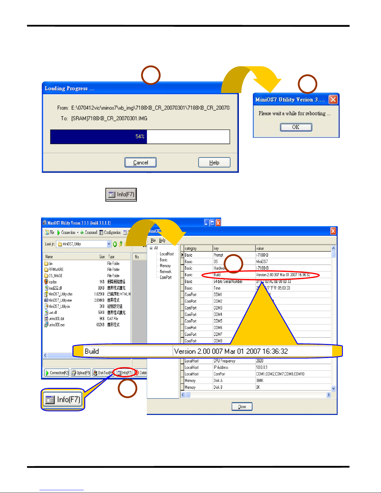
Step 3: It will take about 10 seconds for the upgrade to finish. If the
MiniOS7 was updated successfully, a Confirm action dialog box
will appear.
1
2
Step 4: Press button and see the “Build” item to check the
version number of the MiniOS7. The diagram is as follow:
1
2
Note: Besides using the MiniOS7 Utility to upgrade the MiniOS7,
7188xw.exe can also be used. Refer to Appendix B: MiniOS7 Utility
and 7188XW for download procedures.
I-7188XB Series User’s Manual(Ver.1.0, Apr/2007, 7MH-020-10 ) ---
28
3. Writing Your First Program
3.1 Libraries
There are two function libraries for the I-7188XB(D) module as follows:
7188xbs.lib are programs for the small memory model.
7188xbl.lib are programs for the large memory model.
Both libraries are suitable for TC, BC++, MSC and MSVC++ compilers.
All declared functions are described in the header file, 7188xb.h.
The location of latest Library:
http://ftp.icpdas.com/pub/cd/8000cd/napdos/minios7/minios7_2.0/i-718
8xb/lib/ or CD: \Napdos\MiniOS7\MiniOS7_2.0\i-7188xb\lib
Hundreds of functions are supported in the 7188xbs.lib/7188xbl.lib files
as follows:
Function description Example
COM port
InstallCOM0, InstallCOM1, InstallCOM2 ……
IsCOM0, IsCOM1, IsCOM2 ……
ToCOM0, ToCOM1, ToCOM2 ……
ReadCom0, ReadCom1, ReadCom2 ……
EEPROM WriteEEP, ReadEEP, EnableEEP, ProtectEEP
LED and 5-digit LED LedOn, LedOff, Init5DigitLed, Show5DigitLedWithDot
Flash Memory
FlashReadId, FlashErase, FlashRead,
FlashWrite ……
Timer and Watchdog
Timer
TimerOpen, TimeClose, TimerResetVlaue,
TimerReadValue, StopWatchReset,
StopWatchRead, StopWatchStop
File
GetFileNo, GetFileName, GetFilePositionByNo,
GetFilePositionByName
Connect to 7000 series
modules
SendCmdTo7000, ReceiveResponseFrom7000
Programmable I/O SetDio4Dir, SetDio4High, SetDio4Low, GetDio4
Others Kbhit, Getch, Putch, LineInput, Scanf ……
Note: For a more detailed description of the functions, please refer to
Appendix D: Library Function List.
I-7188XB Series User’s Manual(Ver.1.0, Apr/2007, 7MH-020-10 ) ---
29

3.2 Compiler and Linker
A C Language compiler must be used to develop any applications. Valid
compilers include:
BC++ 3.1~5.02
TC++ 1.01
TC 2.01
MSC
MSVC++ (Prior to version 1.52).
ICP DAS suggests that BC 3.1 is used as the compiler as the libraries
provided have been created using the BC 3.1 compiler. Special
attention should be paid to the following items before using the compiler
to develop custom applications:
Generate a standard DOS executable program.
Set the CPU to 80188/80186
Set the floating point to EMULATION if floating point computation
is required. (Make sure not to choose 8087)
Cancel the Debug Information function as this helps to reduce
program size. (MiniOS7 supports this feature.)
I-7188XB Series User’s Manual(Ver.1.0, Apr/2007, 7MH-020-10 ) ---
30
 Loading...