

I-7088, I-7088D,
M-7088 and M-7088D
User Manual
Warranty
All products manufactured by ICP DAS are warranted against
defective materials for a period of one year from the date of delivery
to the original purchaser.
Warning
ICP DAS assume no liability for any damages consequent to the use
of this product. ICP DAS reserves the right to change this manual at
any time without notice. The information furnished by ICP DAS is
believed to be accurate and reliable. However, no responsibility is
assumed by ICP DAS for its use, nor for any infringements of
patents or other rights of third parties resulting from its use.
Copyright
Copyright © 2010 by ICP DAS Co. Ltd. All rights are reserved.
Trademarks
Names are used for identification purposes only and may be
registered trademarks of their respective companies.
Your Powerful Tools
Create New Ideas
Create New Applications
I-7000 New Features
1. Internal Self Tuner
2. Multiple Baud Rates
3. Multiple Data Formats
4. Internal Dual WatchDog
5. True Distributed Control
6. High Speed & High
Density I/O

I-7088 and M-7088 User Manual, Rev: A1.2 7MH-026-A12
2
Table of Contents
1. Introduction ..................................................................................................5
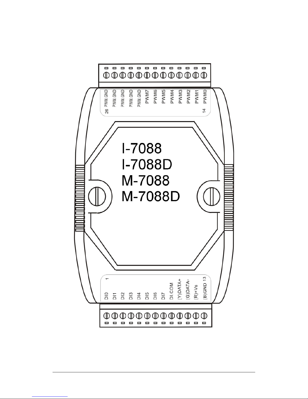
1.1. Pin Assignments ..................................................................................... 7
1.2. Specifications..........................................................................................8
1.3. Block Diagram.......................................................................................10
1.4. Application Wiring ................................................................................. 11
1.4.1. PWM Wiring Connections.............................................................. 11
1.4.2. DI/Counter Wiring Connections...................................................... 11
1.5. Quick Start ............................................................................................12
1.6. Default Settings
.....................................................................................14
1.7. Configuration Tables
.............................................................................15
2. DCON Protocol ........................................................................................... 16
2.1. %AANNTTCCFF...................................................................................21
2.2. #AA .......................................................................................................25
2.3. #AAN.....................................................................................................27
2.4. #AA1cDD ..............................................................................................29
2.5. #AAAcDD..............................................................................................31
2.6. $AA2 .....................................................................................................33
2.7. $AA3N...................................................................................................35
2.8. $AA3N(Data)
.........................................................................................37
2.9. $AA5 .....................................................................................................39
2.10. $AA5VV............................................................................................... 41
2.11. $AA6 ...................................................................................................43
2.12. $AA6N.................................................................................................45
2.13. $AA6NN
..............................................................................................47
2.14. $AA7N.................................................................................................49
2.15. $AA8 ...................................................................................................51
2.16. $AA8V................................................................................................. 53
2.17. $AA9(Data) ......................................................................................... 55
2.18. $AAB................................................................................................... 57
2.19. $AABR ................................................................................................59
2.20. $AACnD.............................................................................................. 61
2.21. $AACnD(Data) ....................................................................................63
2.22. $AACnF...............................................................................................65

I-7088 and M-7088 User Manual, Rev: A1.2 7MH-026-A12
3
2.23. $AACnF(Data)..................................................................................... 67
2.24. $AACnM..............................................................................................69
2.25. $AACnMS ...........................................................................................71
2.26. $AACnP ..............................................................................................73
2.27. $AACnP(Data) .................................................................................... 75
2.28. $AACnT...............................................................................................77
2.29. $AACnTS............................................................................................ 79
2.30. $AACnN.............................................................................................. 81
2.31. $AACnNS............................................................................................83
2.32. $AAF................................................................................................... 85
2.33. $AAI ....................................................................................................87
2.34. $AAM ..................................................................................................89
2.35. $AAP................................................................................................... 91
2.36. $AAPN ................................................................................................93
2.37. $AAR...................................................................................................95
2.38. $AAW.................................................................................................. 97
2.39. $AAYS.................................................................................................99
2.40. @AADODD....................................................................................... 101
2.41. @AADI..............................................................................................103
2.42. @AAGN ............................................................................................105
2.43. @AAPN(Data)................................................................................... 107
2.44. ~AAD................................................................................................. 109
2.45. ~AADVV............................................................................................ 111
2.46. ~AAO(Name)
.....................................................................................113
2.47. ~AARD..............................................................................................115
2.48. ~AARDTT
..........................................................................................117
2.49. ~**..................................................................................................... 119
2.50. ~AA0................................................................................................. 120
2.51. ~AA1................................................................................................. 122
2.52. ~AA2................................................................................................. 124
2.53. ~AA3ETT...........................................................................................126
2.54. ~AAI.................................................................................................. 128
2.55. ~AATnn.............................................................................................130
3. Modbus RTU Protocol .............................................................................. 133
3.1. 02 (0x02) Read PWM Status............................................................... 134
3.2. 04 (0x04) Read DI Count ....................................................................136

I-7088 and M-7088 User Manual, Rev: A1.2 7MH-026-A12
4
3.3. 70 (0x46) Read/Write Modbus Settings............................................... 137
3.3.1. Sub-function 00 (0x00) Read module name................................. 138
3.3.2. Sub-function 04 (0x04) Set module address................................139
3.3.3. Sub-function 05 (0x05) Read communication settings................. 140
3.3.4. Sub-function 06 (0x06) Set communication settings.................... 142
3.3.5. Sub-function 32 (0x20) Read firmware version............................ 144
3.3.6. Sub-function 41 (0x29) Read miscellaneous................................ 145
3.3.7. Sub-function 42 (0x2A) Write miscellaneous settings.................. 146
3.4. M-7088 Address Mappings ................................................................. 147
4. Operation Principles & Application Notes ............................................. 150
4.1. INIT* pin Operation Principles.............................................................150
4.2. PWM Operation Principle....................................................................151
Appendix
.......................................................................................................153
A.1. INIT M
ode...........................................................................................153
A.2. Dual Watchdog Operation................................................................... 155
A.3. Frame Ground .................................................................................... 156
A.4. Node Information Area........................................................................158
A.5. Reset Status....................................................................................... 159

I-7088 and M-7088 User Manual, Rev: A1.2 7MH-026-A12
5
1. Introduction
The I-7088 has 8 PWM output channels and 8 counter inputs and
can be used to develop powerful and cost effective analog control
systems. PWM (Pulse Width Modulation) is a powerful technique for
controlling analog circuits that uses digital outputs to generate a
waveform with a variable Duty Cycle (the fraction of time that a
system is in an "active" state) and frequency to control analog
circuits, and can be used to control the position/speed of motors,
control the brightness of lamps, or control the speed of fans, etc.
The I-7088 will also automatically save the counter value to
EEPROM if the power supply is interrupted or lost. Refer to Section
1.7 for details.
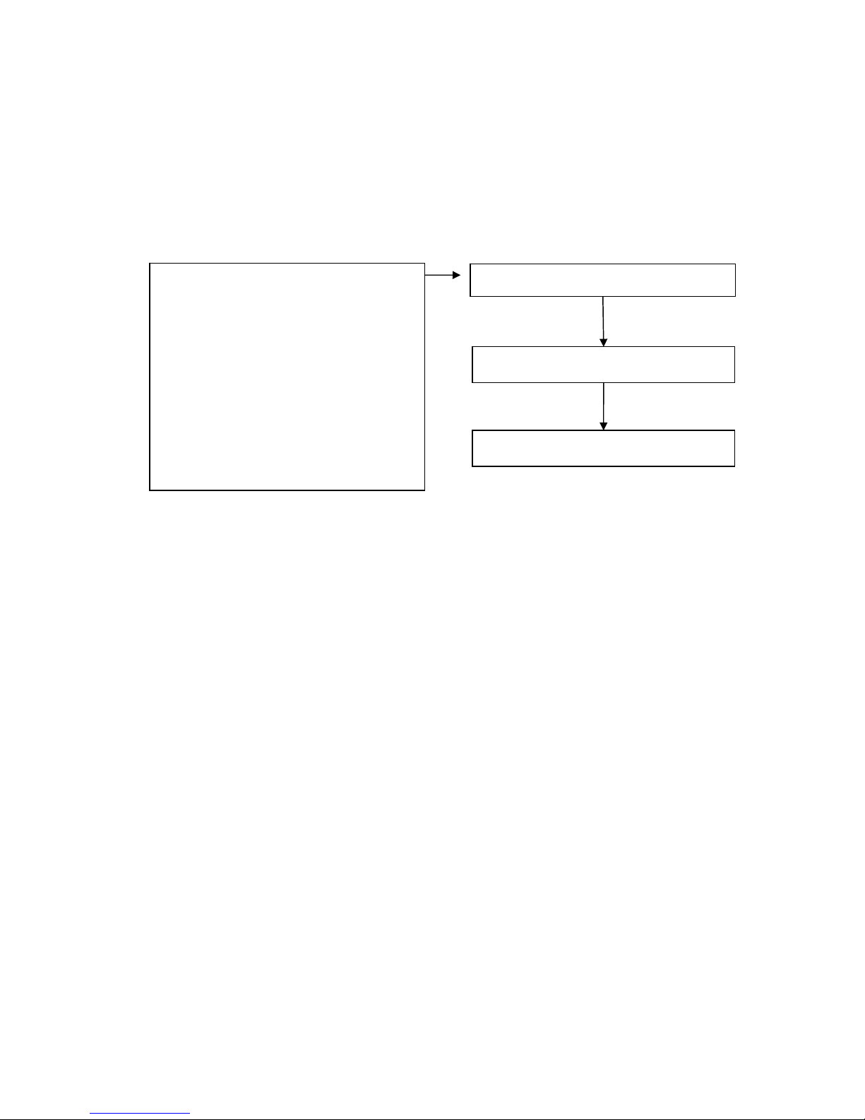
Features
Automatic hardware generation of PWM outputs without the need
for software intervention.
1Hz ~ 500KHz PWM output frequency with 0.1%~99.9% duty
cycle (Refer to Section 4.2).
Software and hardware trigger mode for PWM output.
Individual and synchronous PWM output. By using software
trigger mode, you can set the configuration for all PWM channels
then trigger them either individually or all at the same time.
Burst mode PWM operation for standby.
DI channel can be configured as either a simple digital input
channel or a hardware trigger source for the PWM output.
Software Trigger
PWM (Continuous Mode)
I-7088
MCU
DI / Hardware Trigger
PWM (Burst Mode)

I-7088 and M-7088 User Manual, Rev: A1.2 7MH-026-A12
6
Applications
Controlling the position/speed of motors
Controlling the brightness of lamps
Controlling the speed of fans
More Information
Refer to Chapter 1 of the “I-7000 Bus Converter User Manual” for
more information regarding the following:
1.1. I-7000 Overview
1.2. I-7000 Related Documentation
1.3. I-7000 Common Features
1.4. I-7000 System Network Configuration
1.5. I-7000 Dimensions
I-7088 and M-7088 User Manual, Rev: A1.2 7MH-026-A12
7
1.1. Pin Assignments
I-7088 and M-7088 User Manual, Rev: A1.2 7MH-026-A12
8
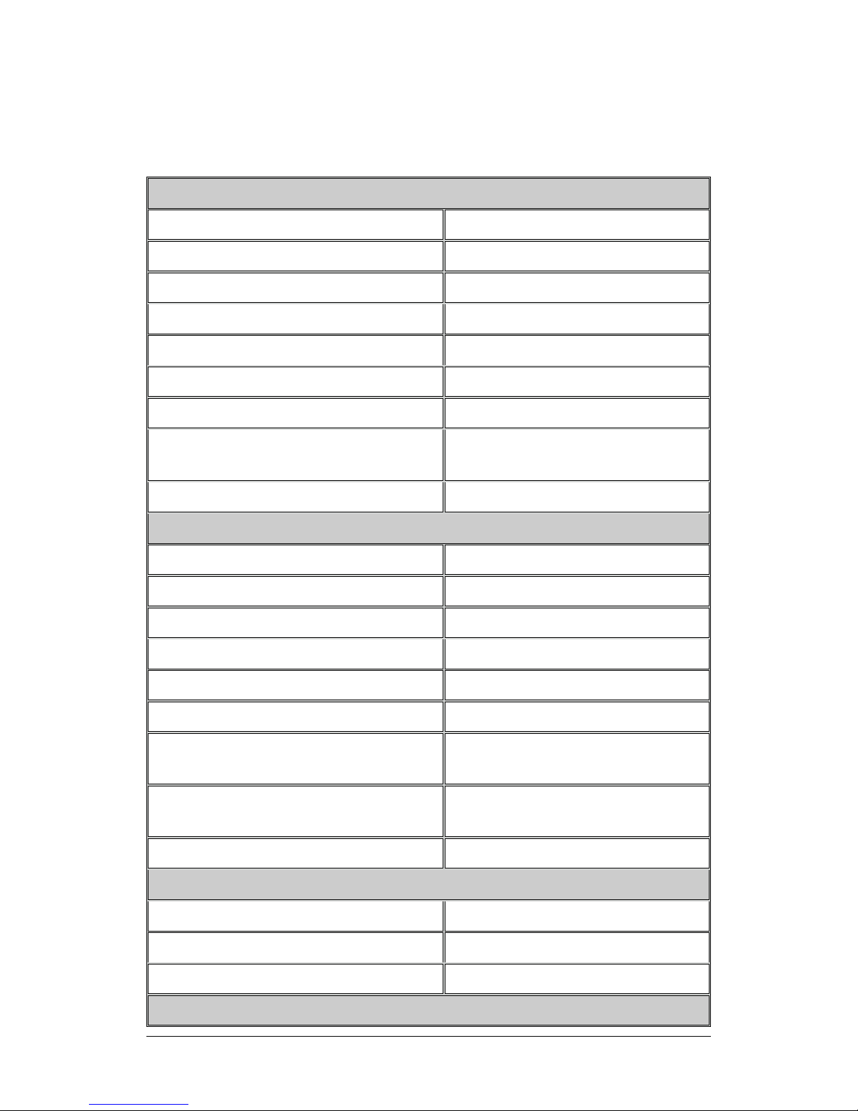
1.2. Specifications
PWM Output
Channels 8
Type TTL, Isolated
Max. Frequency 500 KHz
Duty Cycle 0.1%~99.9%
PWM Mode Burst mode, Continuous mode
Burst Mode Counter 1~65535 counts
Trigger Start Hardware or Software
ESD Protection
4 kV Contact for each terminal
and 8 kV Air for random points
Isolation 2500 V
DC
Digital Input
Channels 8
Type Sink, Isolated
ON Voltage Level +2.4 V~+5 V
OFF Voltage Level +1 V Max.
Max. Frequency 1 MHz
Max. Counts 32bits (4,294,967,295)
Built-in Virtual Battery Backup for
Counter Value
Yes
ESD Protection
4 kV Contact for each terminal
and 8 kV Air for random point
Isolation 2500 V
DC
Interface
Interface RS-485
Format N, 8, 1
Baud Rate 1200 ~ 115200bps
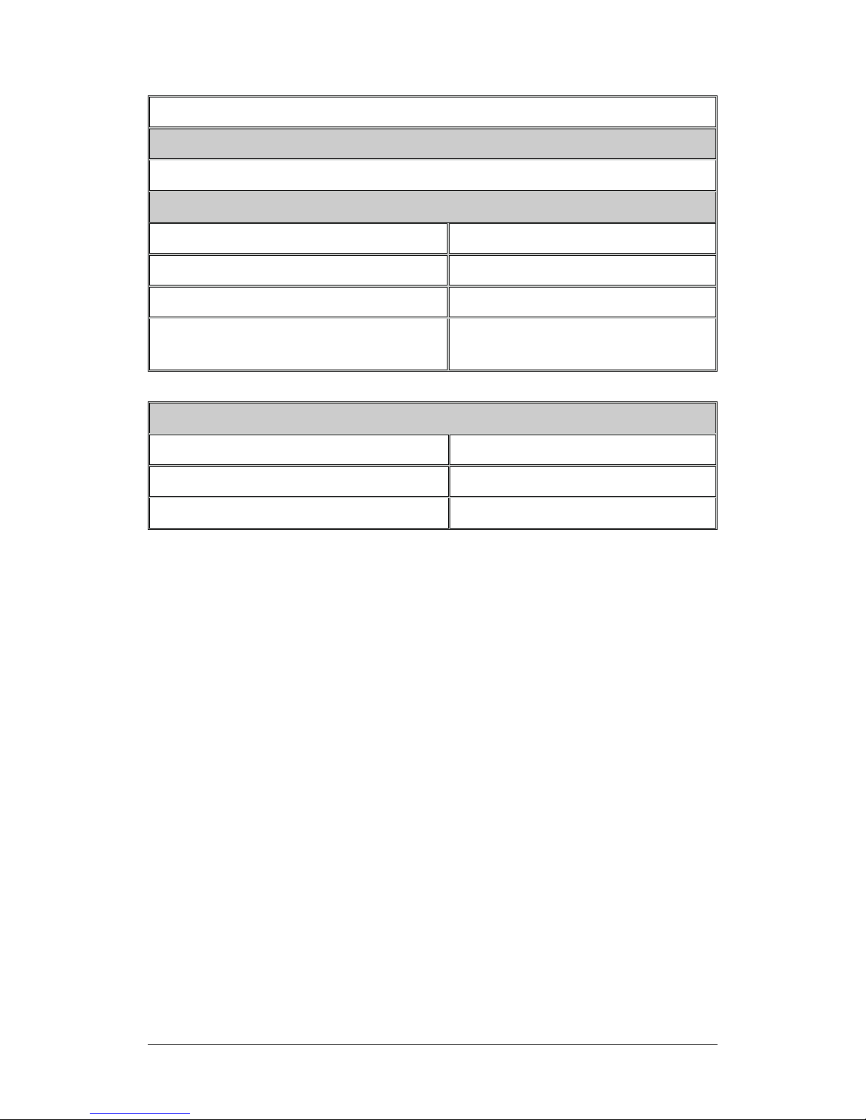
LED Display
I-7088 and M-7088 User Manual, Rev: A1.2 7MH-026-A12
9
1 LED as Power/Communication Indicator
Dimensions
72mm x 122mm x 35mm (W x L x H)
Power
Input Voltage Range 10 ~ 30 VDC
Power Consumption 2.4 W (max.)
Power Reverse Polarity Protection Yes
+/- 4 kV ESD , +/- 4 kV EFT and
+/- 3 kV Surge Protection
Yes
Environment
Operating Temperature -25 ~ 75°C
Storage Temperature -40 ~ 85°C
Humidity 5 ~ 95%, non-condensing
I-7088 and M-7088 User Manual, Rev: A1.2 7MH-026-A12
10
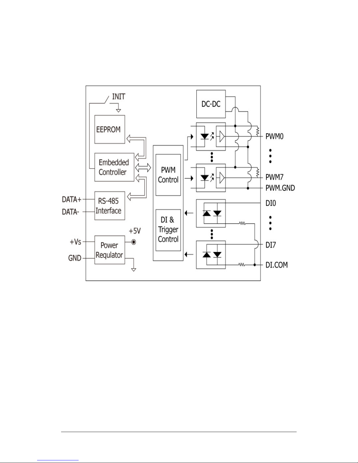
1.3. Block Diagram

I-7088 and M-7088 User Manual, Rev: A1.2 7MH-026-A12
11
1.4. Application Wiring
1.4.1. PWM Wiring Connections
1.4.2. DI/Counter Wiring Connections

I-7088 and M-7088 User Manual, Rev: A1.2 7MH-026-A12
12
1.5. Quick Start
Refer to http://www.icpdas.com/download/7000/manual.htm
and use the “DCON Utility” to control the module. Otherwise, use
“DCON Utility -> Terminal -> Command Line” and follow the
commands shown below.
DI Status and Counter
1. Type @01DI[Enter] Receive => !01xx01
2. Type $01500[Enter] Receive => !01
3. Type @01P200000000[Enter] Receive => !01
4. Type $0132FFFFFFFF[Enter] Receive => !01
5. Type $0162[Enter] Receive => !01
6. Type #012[Enter] Receive => >00000000
7. Type $01504[Enter] Receive => !01
8. Type #012[Enter] Receive => >xxxxxxxx
Step 1: Read the DI status channel 0 = 1, channel 1 = 0, etc.
Step 2: Disable the DI counter of channel 2
Step 3: Set the DI preset counter value (00000000) of channel 2
Step 4: Set the DI max. counter value (FFFFFFFF) of channel 2
Step 5: Reset the DI counter of channel 2
Step 6: Read the DI counter value (00000000) of channel 2
Step 7: Enable the DI counter of channel 2
Step 8: Read the DI counter value (xxxxxxxx) of channel 2

I-7088 and M-7088 User Manual, Rev: A1.2 7MH-026-A12
13
PWM Output
1. Type $01C0F100000[Enter] Receive => !01100000
2. Type $01C0D50.0[Enter] Receive => !0150.0
3. Type $01C0M1[Enter] Receive => !01
4. Type @01DO01[Enter] Receive => !01
Step 1: Set the frequency of PWM channel 0 to 100 KHz
Step 2: Set the duty cycle of PWM channel 0 to 50.0%
Step 3: Set PWM channel 0 to continuous mode
Step 4: Start the output of PWM channel 0

I-7088 and M-7088 User Manual, Rev: A1.2 7MH-026-A12
14
1.6. Default Settings
The default settings are as follows:
Address = 01
Baud Rate = 9600
Checksum disabled
Data = 1 Start + 8 Data + 1 Stop (no parity)
PWM Frequency = 10 KHz
PWM Duty Cycle = 50%
PWM Steps = 1 (Continuous Type)
I-7088 and M-7088 User Manual, Rev: A1.2 7MH-026-A12
15
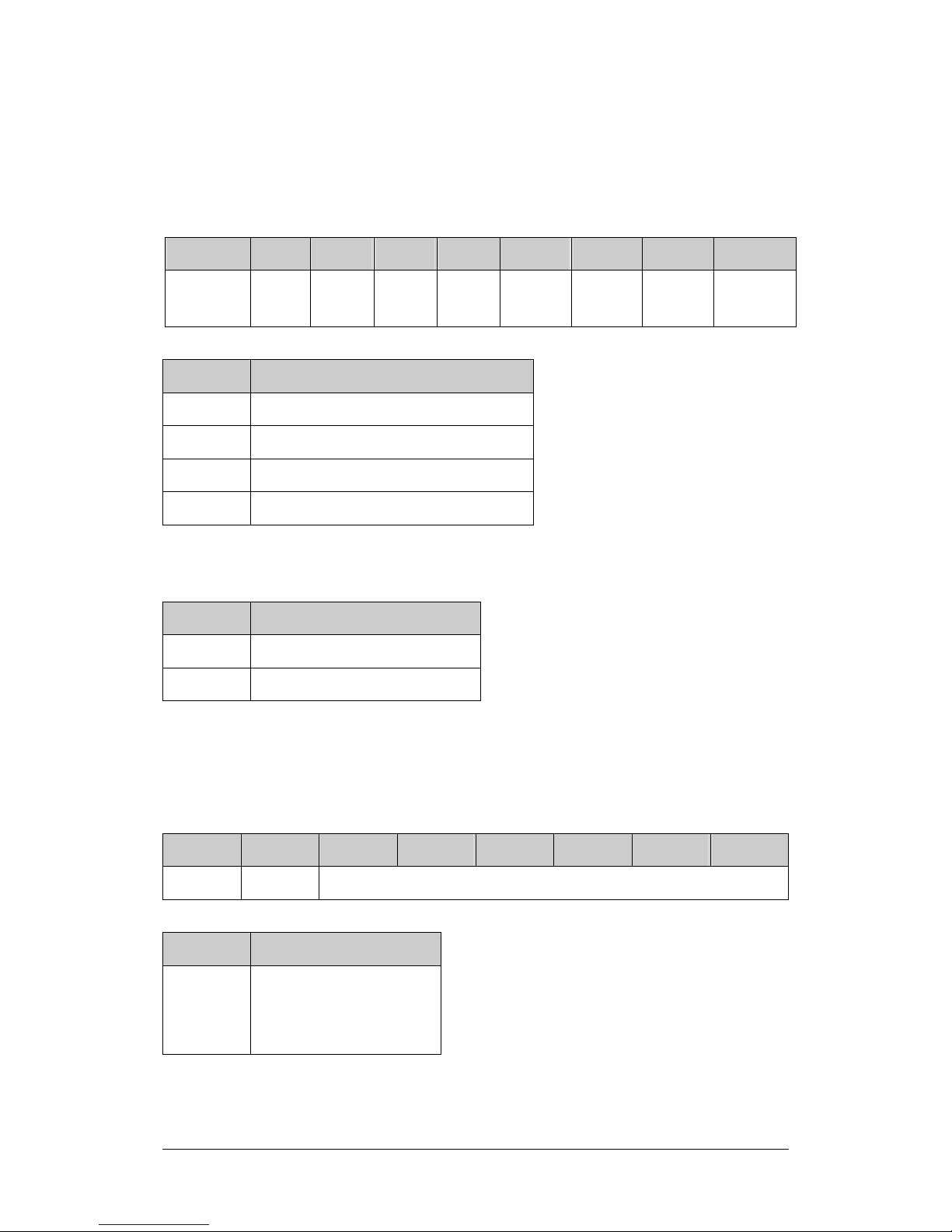
1.7. Configuration Tables
Baud Rate Setting (CC)
Code 03 04 05 06 07 08 09 0A
Baud
Rate
1200 2400 4800 9600 19200 38400 57600 115200
Bits 7:6 Description
00 No parity and one stop bit
01 No parity and two stop bits
10 Even parity and one stop bit
11 Odd parity and one stop bit
Configuration Code Table (TT)
TT Input Range
50 Counter
52 Virtual Battery Backup
Note: For type 52, the count value will continue from the last poweroff value.
Data Format Settings (FF)
7 6 5 4 3 2 1 0
0 CS Reserved
Key Description
CS Checksum setting
0: Disabled
1: Enabled
Note: Reserved bits should be zero.

I-7088 and M-7088 User Manual, Rev: A1.2 7MH-026-A12
16
2. DCON Protocol
All communication with I-7000 modules consists of commands
generated by the host and responses transmitted by the I-7000
module. Each module has a unique ID number that is used for
addressing purposes and is stored in non-volatile memory. The ID is
01 by default and can be changed using a user command. All
commands sent to a module contain the ID address, meaning that
only the addressed module will respond. The only exception to this
is command ~** (Section 2.49), which is sent to all modules, but, in
this case, the modules do not reply to the command.
Command Format:
Leading
Character
Module
Address
Command [CHKSUM] CR
Response Format:
Leading
Character
Module
Address
Data [CHKSUM] CR
CHKSUM A 2-character checksum that is present when the
checksum setting is enabled. See Sections 1.7 and 2.1
for details.
CR The End of command character, carriage return (0x0D)

I-7088 and M-7088 User Manual, Rev: A1.2 7MH-026-A12
17
Checksum Calculation:
Calculate the ASCII code sum of all the characters in the
command/response string, except for the carriage return character
(CR).
The checksum is equal to the sum masked by 0ffh.
Example:
Command string: $012(CR)
The sum of the string = “$”+”0”+”1”+”2” = 24h+30h+31h+32h = B7h
Therefore the checksum is B7h, and so CHKSUM = “B7”
The command string with the checksum = $012B7(CR)
Response string: !01200600(CR)
The sum of the string = “!”+”0”+”1”+”2”+”0”+”0”+”6”+”0”+”0” =
21h+30h+31h+32h+30h+30h+36h+30h+30h = 1AAh
Therefore the checksum is AAh, and so CHKSUM = “AA”
The response string with the checksum = !01200600AA(CR)
Note:
All characters should be in upper case.
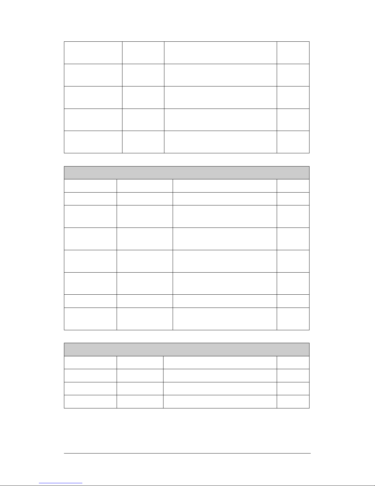
General Command Sets
Command Response Description Section
%AANNTTCCFF !AA
Sets the configuration of
the module
2.1
$AA2 !AANNTTCCFF
Reads the configuration
of the module
2.6
$AA5 !AAS
Reads reset status of
the module
2.9
$AAF !AA(Data)
Reads the firmware
version
2.32
$AAI !AAS
Reads the status of the
INIT switch
2.33

I-7088 and M-7088 User Manual, Rev: A1.2 7MH-026-A12
18
$AAM !AA(Data) Reads the module name 2.34
$AAP !AASC
Reads the
communication protocol
2.35
$AAPN !AA
Sets the communication
protocol
2.36
~AAO(Name) !AA Sets the module name 2.46
~AARD !AATT
Reads the response
delay time
2.47
~AARDTT !AA
Sets the response delay
time
2.48
PWM Command Sets
Command Response Description Section
#AA >(Data) Reads the count 2.2
#AAN >(Data)
Reads the count of a specific
channel
2.3
#AA1cDD >
Sets the output for a specific
PWM channel
2.4
#AAAcDD >
Sets the output for a specific
PWM channel
2.5
$AA3N !AA
Reads the max. counter
value of a specific channel
2.7
$AA3N(data) !AA
Sets the max. counter value
for a specific channel
2.8
$AA5VV !AA
Sets the counter status for a
specific channel
2.10
$AA6 !AASS Reads the counter status 2.11
$AA6N !AA
Resets the counter of a
specific channel
2.12
$AA6NN !AA
Resets the counter of a
specific channel
2.13
$AA7N !AAS
Reads the status of the
overflow for a specific
channel
2.14
$AAB !AAS Reads the power-down count 2.18

I-7088 and M-7088 User Manual, Rev: A1.2 7MH-026-A12
19
$AABR !AA Clears the power-down count 2.19
$AACnD !AA(data)
Reads the duty cycle value of
a specific channel
2.20
$AACnD(data) !AA
Sets the duty cycle value for
a specific channel
2.21
$AACnF !AA(data)
Reads the frequency value of
a specific channel
2.22
$AACnF(data) !AA
Sets the frequency value for
a specific channel
2.23
$AACnM !AAS
Reads the continuous mode
status of a specific channel
2.24
$AACnMS !AA
Sets the continuous mode for
a specific channel
2.25
$AACnP !AA(data)
Reads the PWM step value of
a specific channel
2.26
$AACnP(data) !AA
Sets the PWM step value for
a specific channel
2.27
$AACnT !AAS
Reads the hardware trigger
configuration of a specific
channel
2.28
$AACnTS !AA
Sets the hardware trigger
configuration for a specific
channel
2.29
$AACnN !AAS
Reads the status of the PWM
synchronization of a specific
channel
2.30
$AACnNS !AA
Sets the PWM
synchronization for a specific
channel
2.31
$AAR !AA Resets the PWM 2.37
$AAW !AA Saves the PWM configuration 2.38
$AAYS !AA
Starts the PWM
synchronization
2.39
@AADODD !AA
Sets the status of the PWM
output port
2.40
I-7088 and M-7088 User Manual, Rev: A1.2 7MH-026-A12
20
@AADI !AAOO
Reads the status of the PWM
output port and the DI
2.41
@AAGn !AA(data)
Reads the preset count value
of a specific channel
2.42
@AAPN(data) !AA
Sets the preset count value
for a specific channel
2.43
~AAD !AASS
Reads the miscellaneous
settings
2.44
~AADVV !AA
Sets the miscellaneous
settings
2.45
Host Watchdog Command Sets
Command Response Description Section
~** No Response The Host is OK 2.49
~AA0 !AASS
Reads the status of the
Host Watchdog
2.50
~AA1 !AA
Resets the status of the
Host Watchdog
2.51
~AA2 !AAETT
Reads the Host Watchdog
timeout settings
2.52
~AA3ETT !AA
Sets the Host Watchdog
timeout settings
2.53
~AAI !AA Sets the Software INIT 2.54
~AATnn !AA
Sets the Software INIT
timeout value
2.55
LED Command Sets
Command Response Description Section
$AA8 !AAS Reads the LED configuration 2.15
$AA8V !!AA Sets the LED configuration 2.16
$AA9(data) !!AA Sends the data to the LED 2.17

I-7088 and M-7088 User Manual, Rev: A1.2 7MH-026-A12
21
2.1. %AANNTTCCFF
Description:
This command is used to set the configuration of a module.
Syntax:
%AANNTTCCFF[CHKSUM](CR)
% Delimiter character
AA The address of the module to be configured in
hexadecimal format (00 to FF)
NN The new address of the module in hexadecimal format
(00 to FF)
TT The new Type Code, see Section 1.7 for details
CC The new Baud Rate code, see Section 1.7 for details.
For the I-7088, the rear slide switch must be moved to
the INIT position in order to change the Baud Rate
settings. See Section A.1 for details.
FF The command used to set the checksum, and the input
range settings (Section 1.7). For the I-7088, the rear
slide switch must be moved to the INIT position in order
to change the checksum setting. See Section A.1 for
details.

I-7088 and M-7088 User Manual, Rev: A1.2 7MH-026-A12
22
Response:
Valid Command: !AA[CHKSUM](CR)
InValid Command: ?AA[CHKSUM](CR)
! Delimiter for a valid command
? Delimiter for an invalid command
(If the Baud Rate or checksum settings are changed
without switching the rear slide switch to the INIT
position, the module will return an invalid command.)
AA The address of the module in hexadecimal format (00
to FF)
There will be no response if the command syntax is incorrect, there
is a communication error, or there is no module with the specified
address.
Examples:
Command:
%0102500600
Response:
!02
Changes the address of module 01 to 02 and the module returns a
valid response.
Command:
%0202520600
Response:
!02
Sets the type of module 02 to 52 (Virtual Battery Backup) and the
module returns a valid response.

I-7088 and M-7088 User Manual, Rev: A1.2 7MH-026-A12
23
Command:
%0202520A00
Response:
?02
Changes the Baud Rate of module 02 to 115200bps and the module
returns an invalid response because it is not in INIT mode.
Command:
%0202520A00
Response:
!01
Changes the Baud Rate of module 02 to 115200bps and the module
is in INIT mode. The module returns a valid response.
Related Commands:
Section 2.6 $AA2, Section 2.54 ~AAI, Section 2.55 ~AATnn
Related Topics
Section 1.7 Configuration Tables, Section A.1 INIT Pin Operation

I-7088 and M-7088 User Manual, Rev: A1.2 7MH-026-A12
24
Notes:
1. Changes to the address, Type Code and Data Format settings
take effect immediately after a valid command is received.
Changes to the Baud Rate and checksum settings take effect on
the next power-on reset.
2. For the I-7088, changing the Baud Rate and checksum settings
can only be achieved using software and are performed by using
the following commands:
I. Send an ~AATnn command. See Section 2.55 for details.
II. Send an ~AAI command. See Section 2.54 for details.
III. Send an %AANNTTCCFF command.
If the command is valid, the Baud Rate and checksum settings will
be changed after the module responds with !AA.

I-7088 and M-7088 User Manual, Rev: A1.2 7MH-026-A12
25
2.2. #AA
Description:
This command is used to read the DI count.
Syntax:
#AA[CHKSUM](CR)
# Delimiter character
AA The address of the module to be read (00 to FF)
Response:
Valid Command: >(Data)[CHKSUM](CR)
InValid Command: ?AA[CHKSUM](CR)
> Delimiter character for a valid command
? Delimiter character for an invalid command
(Data) The count data from all DI channels
AA The address of the responding module (00 to FF)
There will be no response if the command syntax is incorrect, there
is a communication error, or there is no module with the specified
address.

I-7088 and M-7088 User Manual, Rev: A1.2 7MH-026-A12
26
Examples:
Command:
#01
Response:
>0000000800000090000000A000000B000000C00000
0D000000E0000000F
Reads module 01 and returns the count of DI channel 0 (8), channel
1 (9), etc.
Related Commands:
Section 2.3 #AAN

I-7088 and M-7088 User Manual, Rev: A1.2 7MH-026-A12
27
2.3. #AAN
Description:
This command is used to read the count of a specific channel.
Syntax:
#AAN[CHKSUM](CR)
# Delimiter character
AA The address of the module to be read (00 to FF)
N The channel to be read, zero based
Response:
Valid Command: >(Data)[CHKSUM](CR)
InValid Command: ?AA[CHKSUM](CR)
> Delimiter character for a valid command
? Delimiter character for an invalid command
(An invalid command is returned if the specified
channel is incorrect)
(Data) The DI count of the specified channel
AA The address of the responding module (00 to FF)
There will be no response if the command syntax is incorrect, there
is a communication error, or there is no module with the specified
address.

I-7088 and M-7088 User Manual, Rev: A1.2 7MH-026-A12
28
Examples:
Command:
#032
Response:
>00000008
Reads data from channel 2 of module 03 and returns a valid
response.
Command:
#029
Response:
?02
Reads data from channel 9 of module 02. An error is returned
because channel 9 is invalid.
Related Commands:
Section 2.2 #AA

I-7088 and M-7088 User Manual, Rev: A1.2 7MH-026-A12
29
2.4. #AA1cDD
Description:
This command is used to set the status of a specific PWM channel.
Syntax:
#AA1cDD[CHKSUM](CR)
# Delimiter character
AA The address of the module to be set (00 to FF)
The command to set the status of the PWM
c Specifies the channel to be set
DD 00: Sets the PWM output port to off
01: Sets the PWM output port to on
Response:
Valid Command: >[CHKSUM](CR)
InValid Command: ?AA[CHKSUM](CR)
> Delimiter character for a valid command
? Delimiter character for an invalid command
AA The address of the responding module (00 to FF)
There will be no response if the command syntax is incorrect, there
is a communication error, or there is no module with the specified
address.

I-7088 and M-7088 User Manual, Rev: A1.2 7MH-026-A12
30
Examples:
Command:
#011201
Response:
>
Sets the output of PWM channel 2 to on and returns a valid
response.
Related Commands:
Section 2.5 #AAAcDD, Section 2.40 @AADODD
Note:
This command is the same as the #AAAcDD command.

I-7088 and M-7088 User Manual, Rev: A1.2 7MH-026-A12
31
2.5. #AAAcDD
Description:
This command is used to set the status of a specific PWM channel.
Syntax:
#AAAcDD[CHKSUM](CR)
# Delimiter character
AA The address of the module to be set (00 to FF)
A The command to set the status of the PWM
c Specifies the channel to be set
DD 00: Sets the PWM output port to off
01: Sets the PWM output port to on
Response:
Valid Command: >[CHKSUM](CR)
InValid Command: ?AA[CHKSUM](CR)
> Delimiter character for a valid command
? Delimiter character for an invalid command
AA The address of the responding module (00 to FF)
There will be no response if the command syntax is incorrect, there
is a communication error, or there is no module with the specified
address.

I-7088 and M-7088 User Manual, Rev: A1.2 7MH-026-A12
32
Examples:
Command:
#01A201
Response:
>
Sets the output of PWM channel 2 to on and returns a valid
response.
Related Commands:
Section 2.4 #AA1cDD, Section 2.40 @AADODD
Note:
This command is the same as the #AA1cDD command.

I-7088 and M-7088 User Manual, Rev: A1.2 7MH-026-A12
33
2.6. $AA2
Description:
This command is used to read the configuration of a module.
Syntax:
$AA2[CHKSUM](CR)
$ Delimiter character
AA The address of the module to be read (00 to FF)
2 The command to read the module configuration
Response:
Valid Command: !AATTCCFF[CHKSUM](CR)
InValid Command: ?AA[CHKSUM](CR)
! Delimiter character for a valid command
? Delimiter character for an invalid command
AA The address of the responding module (00 to FF)
TT The Type Code of the module, see Section 1.7 for
details
CC The Baud Rate code of the module, see Section 1.7 for
details
FF The checksum settings and the input range settings of
the module, see Section 1.7 for details
There will be no response if the command syntax is incorrect, there
is a communication error, or there is no module with the specified
address.

I-7088 and M-7088 User Manual, Rev: A1.2 7MH-026-A12
34
Examples:
Command:
$012
Response:
!01500600
Reads the configuration of module 01 and returns a valid response.
Command:
$022
Response:
!02520600
Reads the configuration of module 02 and returns a valid response.
Related Commands:
Section 2.1 %AANNTTCCFF
Related Topics:
Section 1.7 Configuration Tables

I-7088 and M-7088 User Manual, Rev: A1.2 7MH-026-A12
35
2.7. $AA3N
Description:
This command is used to read the maximum counter value for a
specific channel.
Syntax:
$AA3N[CHKSUM](CR)
$ Delimiter character
AA The address of the module to be read (00 to FF)
3 The command to read the maximum counter value
N The channel to be read, zero based
Response:
Valid Command: !AA(Data)[CHKSUM](CR)
InValid Command: ?AA[CHKSUM](CR)
! Delimiter character for a valid command
? Delimiter character for an invalid command
(An invalid command is returned if the specified
channel is incorrect)
AA The address of the responding module (00 to FF)
(Data) 8 hexadecimal digits (00000001 to FFFFFFFF)
representing the maximum counter value
There will be no response if the command syntax is incorrect, there
is a communication error, or there is no module with the specified
address.

I-7088 and M-7088 User Manual, Rev: A1.2 7MH-026-A12
36
Examples:
Command:
$0130
Response:
!01FFFFFFFF
Reads the maximum counter value of channel 0 at address 01,
returns a value of 4294967295.
Related Commands:
Section 2.8 $AA3N(Data)

I-7088 and M-7088 User Manual, Rev: A1.2 7MH-026-A12
37
2.8. $AA3N(Data)
Description:
This command is used to set the maximum counter value for a
specific channel.
Syntax:
$AA3N[CHKSUM](CR)
$ Delimiter character
AA The address of the module to be set (00 to FF)
3 The command to set the maximum counter value
N The channel to be set, zero based
(Data) 8 hexadecimal digits (00000001 to FFFFFFFF)
representing the maximum counter value
Response:
Valid Command: !AA [CHKSUM](CR)
InValid Command: ?AA[CHKSUM](CR)
! Delimiter character for a valid command
? Delimiter character for an invalid command
AA The address of the responding module (00 to FF)
There will be no response if the command syntax is incorrect, there
is a communication error, or there is no module with the specified
address.

I-7088 and M-7088 User Manual, Rev: A1.2 7MH-026-A12
38
Examples:
Command:
$030FFFFFFFF
Response:
!03
Sets the maximum counter value of counter 0 at address 03 to
4294967295, and returns a response indicating that the command
was successful.
Related Commands:
Section 2.7 $AA3N

I-7088 and M-7088 User Manual, Rev: A1.2 7MH-026-A12
39
2.9. $AA5
Description:
This command is used to read the reset status of a module.
Syntax:
$AA5[CHKSUM](CR)
$ Delimiter character
AA The address of the module to be read (00 to FF)
5 The command to read the reset status of the module
Response:
Valid Command: !AAS[CHKSUM](CR)
InValid Command: ?AA[CHKSUM](CR)
! Delimiter character for a valid command
? Delimiter character for an invalid command
AA The address of the responding module (00 to FF)
S The reset status of the module
0: This is not the first time the command has been sent
since the module was powered on, which denotes that
there has been no module reset since the last $AA5
command was sent.
1: This is the first time the command has been sent
since the module was powered on.
There will be no response if the command syntax is incorrect, there
is a communication error, or there is no module with the specified
address.

I-7088 and M-7088 User Manual, Rev: A1.2 7MH-026-A12
40
Examples:
Command:
$015
Response:
!011
Reads the reset status of module 01. The response shows that it is
the first time the $AA5 command has been sent since the module
was powered on.
Command:
$015
Response:
!010
Reads the reset status of module 01. The response shows that
there has been no module reset since the last $AA5 command was
sent.

I-7088 and M-7088 User Manual, Rev: A1.2 7MH-026-A12
41
2.10. $AA5VV
Description:
This command is used to specify the channel number of the DI
counter to be enabled.
Syntax:
$AA5VV[CHKSUM](CR)
$ Delimiter character
AA The address of the module to be set (00 to FF)
5 The command to set the counter status
VV A two-digit hexadecimal value, where bit 0 corresponds
to channel 0, and bit 1 corresponds channel 1, etc.
When the bit is 0, it denotes that the channel is disabled
and 1 denotes that the channel is enabled.
Response:
Valid Command: !AA [CHKSUM](CR)
InValid Command: ?AA[CHKSUM](CR)
! Delimiter character for a valid command
? Delimiter character for an invalid command
AA The address of the responding module (00 to FF)
There will be no response if the command syntax is incorrect, there
is a communication error, or there is no module with the specified
address.

I-7088 and M-7088 User Manual, Rev: A1.2 7MH-026-A12
42
Examples:
Command:
$0153A
Response:
!01
Enables the DI counter for channels 1, 3, 4 and 5 of module 01, and
disables all other channels. The module returns a valid response.
Related Commands:
Section 2.11 $AA6

I-7088 and M-7088 User Manual, Rev: A1.2 7MH-026-A12
43
2.11. $AA6
Description:
This command is used to read the status of the DI counter.
Syntax:
$AA6[CHKSUM](CR)
$ Delimiter character
AA The address of the module to be read (00 to FF)
6 The command to read the status of the DI counter
Response:
Valid Command: !AAVV[CHKSUM](CR)
InValid Command: ?AA[CHKSUM](CR)
! Delimiter character for a valid command
? Delimiter character for an invalid command
AA The address of the responding module (00 to FF)
VV A two-digit hexadecimal value, where bit 0 corresponds
to channel 0, and bit 1 corresponds channel 1, etc.
When the bit is 0, it denotes that the channel is disabled,
and 1 denotes that the channel is enabled.
There will be no response if the command syntax is incorrect, there
is a communication error, or there is no module with the specified
address.

I-7088 and M-7088 User Manual, Rev: A1.2 7MH-026-A12
44
Examples:
Command:
$016
Response:
!013A
Reads the channel status of module 01 and returns a response of
3A, meaning that channels 1, 3, 4 and 5 are enabled and all other
channels are disabled.
Related Commands:
Section 2.10 $AA5VV

I-7088 and M-7088 User Manual, Rev: A1.2 7MH-026-A12
45
2.12. $AA6N
Description:
This command is used to reset the counter of a specific channel.
Syntax:
$AA6N[CHKSUM](CR)
$ Delimiter character
AA The address of the module to be reset (00 to FF)
6 The command to reset the counter
N Specifies the channel to be reset, zero based
Response:
Valid Command: !AAVV[CHKSUM](CR)
InValid Command: ?AA[CHKSUM](CR)
! Delimiter character for a valid command
? Delimiter character for an invalid command
(An invalid command is returned if the specified
channel is incorrect)
AA The address of the responding module (00 to FF)
There will be no response if the command syntax is incorrect, there
is a communication error, or there is no module with the specified
address.

I-7088 and M-7088 User Manual, Rev: A1.2 7MH-026-A12
46
Examples:
Command:
$0160
Response:
!01
Resets the counter 0 of module 01 to the preset value and returns a
valid response indicating that the command was successful.
Related Commands:
Section 2.42 @AAGN, Section 2.43 @AAPN(Data)

I-7088 and M-7088 User Manual, Rev: A1.2 7MH-026-A12
47
2.13. $AA6NN
Description:
This command is used to reset the DI counter of a specific channel.
Syntax:
$AA6N[CHKSUM](CR)
$ Delimiter character
AA The address of the module to be reset (00 to FF)
6 The command to reset the DI counter
NN A two-digit hexadecimal value, where bit 0 corresponds
to channel 0, bit 1 corresponds channel 1, etc. When
the bit is 0, it means that the channel is inactive, and 1
means that the channel has been reset.
Response:
Valid Command: !AAVV[CHKSUM](CR)
InValid Command: ?AA[CHKSUM](CR)
! Delimiter character for a valid command
? Delimiter character for an invalid command
(An invalid command is returned if the specified
channel is incorrect)
AA The address of the responding module (00 to FF)
There will be no response if the command syntax is incorrect, there
is a communication error, or there is no module with the specified
address.

I-7088 and M-7088 User Manual, Rev: A1.2 7MH-026-A12
48
Examples:
Command:
$01601
Response:
!01
Resets the counter 0 of module 01 to the preset value and returns a
valid response indicating that the command was successful.
Related Commands:
Section 2.42 @AAGN, Section 2.43 @AAPN(Data), Section 2.11
$AA6

I-7088 and M-7088 User Manual, Rev: A1.2 7MH-026-A12
49
2.14. $AA7N
Description:
This command is used to read the status of the overflow flag for a
specific channel.
Syntax:
$AA7N[CHKSUM](CR)
$ Delimiter character
AA The address of the module to be read (00 to FF)
7 The command to read the status of the overflow flag
N Specifies the channel to be read, zero based
Response:
Valid Command: !AAS[CHKSUM](CR)
InValid Command: ?AA[CHKSUM](CR)
! Delimiter character for a valid command
? Delimiter character for an invalid command
(An invalid command is returned if the specified
channel is incorrect.)
AA The address of the responding module (00 to FF)
S The overflow flag of channel N
0: The counter has not exceeded the maximum counter
value and the overflow flag has been cleared.
1: The counter has exceeded the maximum counter
value and the overflow flag has been set.

I-7088 and M-7088 User Manual, Rev: A1.2 7MH-026-A12
50
There will be no response if the command syntax is incorrect, there
is a communication error, or there is no module with the specified
address.
Examples:
Command:
$0170
Response:
!010
Reads the status of the overflow flag for counter 0 of module 01 and
returns a response indicating that the counter has not been
exceeded.
Related Commands:
Section 2.7 $AA3N, Section 2.8 $AA3N(Data), Section 2.12 $AA6N,
Section 2.13 $AA6NN

I-7088 and M-7088 User Manual, Rev: A1.2 7MH-026-A12
51
2.15. $AA8
Description:
This command is used to read the configuration of the LED.
Syntax:
$AA8[CHKSUM](CR)
$ Delimiter character
AA The address of the module to be read (00 to FF)
8 The command to read the configuration of the LED
Response:
Valid Command: !AAS[CHKSUM](CR)
InValid Command: ?AA[CHKSUM](CR)
! Delimiter character for a valid command
? Delimiter character for an invalid command
(An invalid command is returned if the specified
channel is incorrect.)
AA The address of the responding module (00 to FF)
S 0~7: Shows the count of channels 0~7
8: Rotates the count of channels 0~7
9: Shows the host control
There will be no response if the command syntax is incorrect, there
is a communication error, or there is no module with the specified
address.

I-7088 and M-7088 User Manual, Rev: A1.2 7MH-026-A12
52
Examples:
Command:
$018
Response:
!010
Read the configuration of the LED and returns a response indicating
the LED is showing the count for DI channel 0.
Related Commands:
Section 2.16 $AA8V, Section 2.17 $AA9(Data)

I-7088 and M-7088 User Manual, Rev: A1.2 7MH-026-A12
53
2.16. $AA8V
Description:
This command is used to set the configuration of the LED.
Syntax:
$AA8[CHKSUM](CR)
$ Delimiter character
AA The address of the module to be set (00 to FF)
The command to set the configuration of the LED
V 0~7: Shows the count of channels 0~7
8: Rotates mode
9: Host control mode
Response:
Valid Command: !AA[CHKSUM](CR)
InValid Command: ?AA[CHKSUM](CR)
! Delimiter character for a valid command
? Delimiter character for an invalid command
(An invalid command is returned if the specified
channel is incorrect.)
AA The address of the responding module (00 to FF)
There will be no response if the command syntax is incorrect, there
is a communication error, or there is no module with the specified
address.

I-7088 and M-7088 User Manual, Rev: A1.2 7MH-026-A12
54
Examples:
Command:
$0181
Response:
!01
Sets the LED to show the count for DI channel 1 and returns a valid
response.
Related Commands:
Section 2.15 $AA8V, Section 2.17 $AA9(Data)

I-7088 and M-7088 User Manual, Rev: A1.2 7MH-026-A12
55
2.17. $AA9(Data)
Description:
This command is used to send data to the LED display.
Syntax:
$AA8[CHKSUM](CR)
$ Delimiter character
AA The address of the module where the data is to be sent
(00 to FF)
The command to send data to the LED display
(Data) 5 decimal digits + 1 decimal point
(Max. = 99999. , Min. = 0.0000 )
Response:
Valid Command: !AA[CHKSUM](CR)
InValid Command: ?AA[CHKSUM](CR)
! Delimiter character for a valid command
? Delimiter character for an invalid command
(An invalid command is returned if the specified
channel is incorrect.)
AA The address of the responding module (00 to FF)
There will be no response if the command syntax is incorrect, there
is a communication error, or there is no module with the specified
address.

I-7088 and M-7088 User Manual, Rev: A1.2 7MH-026-A12
56
Examples:
Command:
$0199999.
Response:
!01
Displays “99999.” when the configuration LED is set to Host Control
mode and returns a valid response.
Related Commands:
Section 2.15 $AA8V, Section 2.16 $AA8V

I-7088 and M-7088 User Manual, Rev: A1.2 7MH-026-A12
57
2.18. $AAB
Description:
This command is used to read the power-down count.
Syntax:
$AAB[CHKSUM](CR)
$ Delimiter character
AA The address of the module to be read (00 to FF)
B The command to read the power-down count
Response:
Valid Command: !AA(Data)[CHKSUM](CR)
InValid Command: ?AA[CHKSUM](CR)
! Delimiter character for a valid command
? Delimiter character for an invalid command
AA The address of the responding module (00 to FF)
(Data) 2 hexadecimal digits (00 to FF) representing the count
data
There will be no response if the command syntax is incorrect, there
is a communication error, or there is no module with the specified
address.

I-7088 and M-7088 User Manual, Rev: A1.2 7MH-026-A12
58
Examples:
Command:
$01B
Response:
!0110
Reads the power-down count for module 01 and returns a response
indicating that has happened 16 times.
Related Commands:
Section 2.19 $AABR

I-7088 and M-7088 User Manual, Rev: A1.2 7MH-026-A12
59
2.19. $AABR
Description:
This command is used to clear the power-down count.
Syntax:
$AABR[CHKSUM](CR)
$ Delimiter character
AA The address of the module to be read (00 to FF)
BR The command to clear the power-down count
Response:
Valid Command: !AA[CHKSUM](CR)
InValid Command: ?AA[CHKSUM](CR)
! Delimiter character for a valid command
? Delimiter character for an invalid command
AA The address of the responding module (00 to FF)
There will be no response if the command syntax is incorrect, there
is a communication error, or there is no module with the specified
address.

I-7088 and M-7088 User Manual, Rev: A1.2 7MH-026-A12
60
Examples:
Command:
$01B
Response:
!0110
Reads the power-down count of module 01 and returns a response
indicating that has happened 16 times.
Command:
$01BR
Response:
!01
Clears the power-down count of module 01 and returns a valid
response indicating that the command was successful.
Command:
$01B
Response:
!0100
Reads the power-down count of module 01 and returns a response
indicating that a power-down event has never occurred.
Related Commands:
Section 2.18 $AAB

I-7088 and M-7088 User Manual, Rev: A1.2 7MH-026-A12
61
2.20. $AACnD
Description:
This command is used to read the duty cycle value of a specific
channel.
Syntax:
$AACnD[CHKSUM](CR)
$ Delimiter character
AA The address of the module to be read (00 to FF)
Cn Specifies the channel to be read
D The command to read the duty cycle value
Response:
Valid Command: !AA(Data)[CHKSUM](CR)
InValid Command: ?AA[CHKSUM](CR)
! Delimiter character for a valid command
? Delimiter character for an invalid command
(An invalid command is returned if the specified
channel is incorrect.)
AA The address of the responding module (00 to FF)
(Data) The duty cycle value for the specified channel (00.1 to
99.9)
There will be no response if the command syntax is incorrect, there
is a communication error, or there is no module with the specified
address.

I-7088 and M-7088 User Manual, Rev: A1.2 7MH-026-A12
62
Examples:
Command:
$01C0D
Response:
!0150.0
Reads the duty cycle value for PWM channel 0 of module 01 and
returns a value of 50%.
Command:
$01C1D
Response:
!0133.3
Reads the duty cycle value for PWM channel 1 of module 01 and
returns a value of 33.3%.
Related Commands:
Section 2.21 $AACnD(Data)

I-7088 and M-7088 User Manual, Rev: A1.2 7MH-026-A12
63
2.21. $AACnD(Data)
Description:
This command is used to set the duty cycle value for a specific
channel.
Syntax:
$AACnD[CHKSUM](CR)
$ Delimiter character
AA The address of the module to be set (00 to FF)
Cn Specifies the channel to be set
D The command to set the duty cycle value
(Data) The duty cycle value for the specified channel (00.1 to
99.9)
Response:
Valid Command: !AA(Data)[CHKSUM](CR)
InValid Command: ?AA[CHKSUM](CR)
! Delimiter character for a valid command
? Delimiter character for an invalid command
AA The address of the responding module (00 to FF)
(Data) The actual duty cycle value for the specified channel
(00.1 to 99.9)
There will be no response if the command syntax is incorrect, there
is a communication error, or there is no module with the specified
address.

I-7088 and M-7088 User Manual, Rev: A1.2 7MH-026-A12
64
Examples:
Command:
$01C0D50.0
Response:
!0150.0
Sets the duty cycle value for PWM channel 0 of module 01 to 50%
and returns the true output value of 50%.
Command:
$01C1D33.4
Response:
!0133.3
Sets the duty cycle of PWM channel 1 of module 01 to 33.4% and
returns the true output value of 33.3%.
Related Commands:
Section 2.20 $AACnD

I-7088 and M-7088 User Manual, Rev: A1.2 7MH-026-A12
65
2.22. $AACnF
Description:
This command is used to read the frequency value of a specific
channel.
Syntax:
$AACnF[CHKSUM](CR)
$ Delimiter character
AA The address of the module to be read (00 to FF)
Cn Specifies the channel to be read
F The command to read the frequency value
Response:
Valid Command: !AA(Data)[CHKSUM](CR)
InValid Command: ?AA[CHKSUM](CR)
! Delimiter character for a valid command
? Delimiter character for an invalid command
(An invalid command is returned if the specified
channel is incorrect.)
AA The address of the responding module (00 to FF)
(Data) The actual frequency value for the specified channel
(000001 to 500000)
There will be no response if the command syntax is incorrect, there
is a communication error, or there is no module with the specified
address.

I-7088 and M-7088 User Manual, Rev: A1.2 7MH-026-A12
66
Examples:
Command:
$01C0F
Response:
!01500000
Reads the frequency value for PWM channel 0 of module 01 and
returns a value of 500 KHz.
Command:
$01C2F
Response:
!01000001
Reads the frequency value for PWM channel 2 of module 01 and
returns a value of 1 Hz.
Related Commands:
Section 2.23 $AACnF(Data)

I-7088 and M-7088 User Manual, Rev: A1.2 7MH-026-A12
67
2.23. $AACnF(Data)
Description:
This command is used to set the frequency value for a specific
channel.
Syntax:
$AACnF(Data)[CHKSUM](CR)
$ Delimiter character
AA The address of the module to be set (00 to FF)
Cn Specifies the channel to be set
F The command to set the frequency value
(Data) The frequency value for the specified channel (000001
to 500000)
Response:
Valid Command: !AA(Data)[CHKSUM](CR)
InValid Command: ?AA[CHKSUM](CR)
! Delimiter character for a valid command
? Delimiter character for an invalid command
AA The address of the responding module (00 to FF)
(Data) The actual frequency value for the specified channel
(000001 to 500000)
There will be no response if the command syntax is incorrect, there
is a communication error, or there is no module with the specified
address.

I-7088 and M-7088 User Manual, Rev: A1.2 7MH-026-A12
68
Examples:
Command:
$01C0F500000
Response:
!01500000
Sets the frequency value for PWM channel 0 of module 01 to 500
KHz and returns the actual frequency of 500 KHz. The duty cycle
value will be automatically set to 50.0%.
Command:
$01C2F340000
Response:
!01333333
Sets the frequency value for PWM channel 2 of module 01 to 340
KHz and returns the actual frequency of 333333 Hz. The duty cycle
value will be automatically set to 33.3%.
Related Commands:
Section 2.22 $AACnF
Note:
After using the $AACnF(Data) command, the duty cycle value will be
automatically reset to 50.0%.

I-7088 and M-7088 User Manual, Rev: A1.2 7MH-026-A12
69
2.24. $AACnM
Description:
This command is used to read the continuous mode status of a
specific channel.
Syntax:
$AACnM[CHKSUM](CR)
$ Delimiter character
AA The address of the module to be read (00 to FF)
Cn Specifies the channel to be read
M The command to read the continuous mode
Response:
Valid Command: !AAS[CHKSUM](CR)
InValid Command: ?AA[CHKSUM](CR)
! Delimiter character for a valid command
? Delimiter character for an invalid command
(An invalid command is returned if the specified
channel is incorrect)
AA The address of the responding module (00 to FF)
S 0: PWM continuous mode is disabled
1: PWM continuous mode is enabled
There will be no response if the command syntax is incorrect, there
is a communication error, or there is no module with the specified
address.

I-7088 and M-7088 User Manual, Rev: A1.2 7MH-026-A12
70
Examples:
Command:
$01C0M
Response:
!010
Reads the PWM continuous mode of channel 0 and returns a
response indicating that it is disabled.
Command:
$01C1M
Response:
!011
Reads the PWM continuous mode of channel 1 and returns a
response indicating that it is enabled.
Related Commands:
Section 2.25 $AACnMS, Section 2.26 $AACnP, Section 2.27
$AACnP(Data)

I-7088 and M-7088 User Manual, Rev: A1.2 7MH-026-A12
71
2.25. $AACnMS
Description:
This command is used to set the continuous mode for a specific
channel.
Syntax:
$AACnMS[CHKSUM](CR)
$ Delimiter character
AA The address of the module to be set (00 to FF)
Cn Specifies the channel to be set
M The command to set the continuous mode
S 0: Disables the PWM continuous mode
1: Enables the PWM continuous mode
(If the PWM continuous mode is enabled, the step
value for PWM will be automatically set to 1)
Response:
Valid Command: !AA[CHKSUM](CR)
InValid Command: ?AA[CHKSUM](CR)
! Delimiter character for a valid command
? Delimiter character for an invalid command
AA The address of the responding module (00 to FF)
There will be no response if the command syntax is incorrect, there
is a communication error, or there is no module with the specified
address.

I-7088 and M-7088 User Manual, Rev: A1.2 7MH-026-A12
72
Examples:
Command:
$01C0M1
Response:
!01
Sets the PWM continuous mode of channel 0 to enabled and returns
a valid response. The PWM step value will be automatically set to 1.
Command:
$01C1M0
Response:
!01
Sets the PWM continuous mode of channel 1 to disabled and
returns a valid response. The PWM step value will not be affected.
Related Commands:
Section 2.24 $AACnM, Section 2.26 $AACnP, Section 2.27
$AACnP(Data)

I-7088 and M-7088 User Manual, Rev: A1.2 7MH-026-A12
73
2.26. $AACnP
Description:
This command is used to read the PWM step value of a specific
channel.
Syntax:
$AACnP[CHKSUM](CR)
$ Delimiter character
AA The address of the module to be read (00 to FF)
Cn Specifies the channel to be read
P The command to read the PWM step value
Response:
Valid Command: !AA(Data)[CHKSUM](CR)
InValid Command: ?AA[CHKSUM](CR)
! Delimiter character for a valid command
? Delimiter character for an invalid command
(An invalid command is returned if the specified
channel is incorrect)
AA The address of the responding module (00 to FF)
(Data) The PWM step value (0001 to FFFF)
There will be no response if the command syntax is incorrect, there
is a communication error, or there is no module with the specified
address.

I-7088 and M-7088 User Manual, Rev: A1.2 7MH-026-A12
74
Examples:
Command:
$01C0P
Response:
!01001A
Reads the PWM step value for channel 0 and returns a value of 26
steps.
Command:
$01C1P
Response:
!011000
Reads the PWM step value for channel 1 and returns a value of
4096 steps.
Related Commands:
Section 2.24 $AACnM, Section 2.25 $AACnMS, Section 2.27
$AACnP(Data)

I-7088 and M-7088 User Manual, Rev: A1.2 7MH-026-A12
75
2.27. $AACnP(Data)
Description:
This command is used to set the PWM step value for a specific
channel.
Syntax:
$AACnP(Data)[CHKSUM](CR)
$ Delimiter character
AA The address of the module to be set (00 to FF)
Cn Specifies the channel to be set
P The command to set the PWM step value
(Data) The PWM steps (0001 to FFFF)
(When set to more than 1 step, the PWM continuous
mode will be automatically set to disabled)
Response:
Valid Command: !AA[CHKSUM](CR)
InValid Command: ?AA[CHKSUM](CR)
! Delimiter character for a valid command
? Delimiter character for an invalid command
AA Address of the responding module (00 to FF)
There will be no response if the command syntax is incorrect, there
is a communication error, or there is no module with the specified
address.

I-7088 and M-7088 User Manual, Rev: A1.2 7MH-026-A12
76
Examples:
Command:
$01C0P0001
Response:
!01
Sets the PWM step value for channel 0 to 1 and returns a valid
response.
Command:
$01C1P001A
Response:
!01
Sets the PWM step value for channel 1 to 4096 steps and returns a
valid response. The PWM continuous mode for channel 1 will be
automatically set to disabled.
Related Commands:
Section 2.24 $AACnM, Section 2.25 $AACnMS, Section 2.26
$AACnP

I-7088 and M-7088 User Manual, Rev: A1.2 7MH-026-A12
77
2.28. $AACnT
Description:
This command is used to read the status of the PWM hardware
trigger of a specific channel.
Syntax:
$AACnT[CHKSUM](CR)
$ Delimiter character
AA The address of the module to be read (00 to FF)
Cn Specifies the channel to be read
T The command to read the PWM hardware trigger
Response:
Valid Command: !AAS[CHKSUM](CR)
InValid Command: ?AA[CHKSUM](CR)
! Delimiter character for a valid command
? Delimiter character for an invalid command
(An invalid command is returned if the specified
channel is incorrect)
AA The address of the responding module (00 to FF)
S 0: The hardware trigger is disabled
1: The trigger start is enabled
2: The trigger stop is enabled
There will be no response if the command syntax is incorrect, there
is a communication error, or there is no module with the specified
address.

I-7088 and M-7088 User Manual, Rev: A1.2 7MH-026-A12
78
Examples:
Command:
$01C0T
Response:
!011
Reads the status of the hardware trigger for PWM channel 0 and
returns a response indicating that the PWM channel 0 trigger will
start when the rising edge of the DI is received.
Command:
$01C1T
Response:
!010
Reads the status of the hardware trigger for PWM channel 1 and
returns a response indicating that PWM channel 1 will not be
affected when the rising edge of the DI is received.
Related Commands:
Section 2.29 $AACnTS

I-7088 and M-7088 User Manual, Rev: A1.2 7MH-026-A12
79
2.29. $AACnTS
Description:
This command is used to set the hardware trigger for a specific
channel.
Syntax:
$AACnTS[CHKSUM](CR)
$ Delimiter character
AA The address of the module to be set (00 to FF)
Cn Specifies the channel to be set
T The command to set the PWM hardware trigger
S 0: Disables the hardware trigger
1: Enables the trigger start
2: Enables the trigger stop
Response:
Valid Command: !AA[CHKSUM](CR)
InValid Command: ?AA[CHKSUM](CR)
! Delimiter character for a valid command
? Delimiter character for an invalid command
(An invalid command is returned if the specified
channel is incorrect)
AA The address of the responding module (00 to FF)
There will be no response if the command syntax is incorrect, there
is a communication error, or there is no module with the specified
address.

I-7088 and M-7088 User Manual, Rev: A1.2 7MH-026-A12
80
Examples:
Command:
$01C0T2
Response:
!01
Sets the status of the hardware trigger for PWM channel 0 to trigger
stop and returns a valid response. When the rising edge of the DI is
received, the status of the PWM will be set to trigger stop.
Command:
$01C1T0
Response:
!010
Sets the status of the hardware trigger for PWM channel 1 to
disabled and returns a valid response. The PWM channel 1will not
be affected when the rising edge of the DI is received.
Related Commands:
Section 2.28 $AACnT

I-7088 and M-7088 User Manual, Rev: A1.2 7MH-026-A12
81
2.30. $AACnN
Description:
This is command is used to read the PWM synchronization status of
a specific channel.
Syntax:
$AACnN[CHKSUM](CR)
$ Delimiter character
AA The address of the module to be read (00 to FF)
Cn Specifies the channel to be read
N The command to read the PWM synchronization status
Response:
Valid Command: !AAS[CHKSUM](CR)
InValid Command: ?AA[CHKSUM](CR)
! Delimiter character for a valid command
? Delimiter character for an invalid command
(An invalid command is returned if the specified
channel is incorrect)
AA The address of the responding module (00 to FF)
S 0: PWM synchronization is disabled
1: PWM synchronization is enabled
There will be no response if the command syntax is incorrect, there
is a communication error, or there is no module with the specified
address.

I-7088 and M-7088 User Manual, Rev: A1.2 7MH-026-A12
82
Examples:
Command:
$01C0N
Response:
!011
Reads the synchronization status of PWM channel 0 and returns a
response indicating that it is enabled.
Command:
$01C1N
Response:
!010
Reads the synchronization status of PWM channel 1 and return a
response indicating that it is disabled.
Related Commands:
Section 2.31 $AACnNS, Section 2.39 $AAYS

I-7088 and M-7088 User Manual, Rev: A1.2 7MH-026-A12
83
2.31. $AACnNS
Description:
This command is used to set the PWM synchronization status for a
specific channel.
Syntax:
$AACnN[CHKSUM](CR)
$ Delimiter character
AA The address of the module to be set (00 to FF)
Cn Specifies the channel to be set
N The command to set the PWM synchronization
S 0: Disables the PWM synchronization
1: Enables the PWM synchronization
Response:
Valid Command: !AA[CHKSUM](CR)
InValid Command: ?AA[CHKSUM](CR)
! Delimiter character for a valid command
? Delimiter character for an invalid command
(An invalid command is returned if the specified
channel is incorrect)
AA The address of the responding module (00 to FF)
There will be no response if the command syntax is incorrect, there
is a communication error, or there is no module with the specified
address.

I-7088 and M-7088 User Manual, Rev: A1.2 7MH-026-A12
84
Examples:
Command:
$01C0N1
Response:
!01
Sets the synchronization status for PWM channel 0 to enabled and
returns a valid response.
Command:
$01C1N0
Response:
!01
Sets the synchronization status for PWM channel 1 to disabled and
returns a valid response.
Related Commands:
Section 2.30 $AACnN, Section 2.39 $AAYS

I-7088 and M-7088 User Manual, Rev: A1.2 7MH-026-A12
85
2.32. $AAF
Description:
This command is used to read the firmware version of a module.
Syntax:
$AAF[CHKSUM](CR)
$ Delimiter character
AA The address of the module to be read (00 to FF)
F The command to read the firmware version
Response:
Valid Command: !AA(Data)[CHKSUM](CR)
InValid Command: ?AA[CHKSUM](CR)
! Delimiter character for a valid command
? Delimiter character for an invalid command
AA The address of the responding module (00 to FF)
(Data) The firmware version of the module as a string value
There will be no response if the command syntax is incorrect, there
is a communication error, or there is no module with the specified
address.

I-7088 and M-7088 User Manual, Rev: A1.2 7MH-026-A12
86
Examples:
Command:
$01F
Response:
!01A2.0
Reads the firmware version of module 01 and shows that it is
version A2.0.
Command:
$02F
Response:
!02B1.1
Reads the firmware version of module 02 and shows that it is
version B1.1.

I-7088 and M-7088 User Manual, Rev: A1.2 7MH-026-A12
87
2.33. $AAI
Description:
This command is used to read the status of the INIT switch of a
module.
Syntax:
$AAI[CHKSUM](CR)
$ Delimiter character
AA The address of the module to be read (00 to FF)
I The command to read the status of the INIT switch of
the module
Response:
Valid Command: !AAS[CHKSUM](CR)
InValid Command: ?AA[CHKSUM](CR)
! Delimiter character for a valid command
? Delimiter character for an invalid command
AA The address of the responding module (00 to FF)
S 0: The INIT switch is in the INIT position
1: The INIT switch is in the Normal position
There will be no response if the command syntax is incorrect, there
is a communication error, or there is no module with the specified
address.

I-7088 and M-7088 User Manual, Rev: A1.2 7MH-026-A12
88
Examples:
Command:
$01I
Response:
!010
Reads the status of the INIT switch of module 01. The response
shows that the INIT switch is in the INIT position.

I-7088 and M-7088 User Manual, Rev: A1.2 7MH-026-A12
89
2.34. $AAM
Description:
This command is used to read the name of a module.
Syntax:
$AAM[CHKSUM](CR)
$ Delimiter character
AA The address of the module to be read (00 to FF)
M The command to read the module name
Response:
Valid Command: !AA(Data)[CHKSUM](CR)
InValid Command: ?AA[CHKSUM](CR)
! Delimiter character for a valid command
? Delimiter character for an invalid command
AA The address of the responding module (00 to FF)
(Name) The name of the module as a string value
There will be no response if the command syntax is incorrect, there
is a communication error, or there is no module with the specified
address.

I-7088 and M-7088 User Manual, Rev: A1.2 7MH-026-A12
90
Examples:
Command:
$01M
Response:
!017088
Reads the name of module 01 and returns the name “7088”.
Related Commands:
Section 2.46 ~AAO(Name)

I-7088 and M-7088 User Manual, Rev: A1.2 7MH-026-A12
91
2.35. $AAP
Description:
This command is used to read which communication protocol is
supported and being used by the module.
Syntax:
$AAM[CHKSUM](CR)
$ Delimiter character
AA The address of the module to be read (00 to FF)
P The command to read the communication protocol
Response:
Valid Command: !AASC[CHKSUM](CR)
InValid Command: ?AA[CHKSUM](CR)
! Delimiter character for a valid command
? Delimiter character for an invalid command
AA The address of the responding module (00 to FF)
S 0: Only the DCON protocol is supported
1: Both the DCON and Modbus RTU protocols are
supported
C 0: The protocol set in EEPROM is DCON
1: The protocol set in EEPROM is Modbus RTU
There will be no response if the command syntax is incorrect, there
is a communication error, or there is no module with the specified
address.

I-7088 and M-7088 User Manual, Rev: A1.2 7MH-026-A12
92
Examples:
Command:
$01P
Response:
!0110
Reads which communication protocol is being used by module 01
and returns a response of 10 meaning that it supports both the
DCON and Modbus RTU protocols and the protocol that will be used
at the next power-on reset is DCON.
Related Commands:
Section 2.36 $AAPN

I-7088 and M-7088 User Manual, Rev: A1.2 7MH-026-A12
93
2.36. $AAPN
Description:
This command is used to set the communication protocol.
Syntax:
$AAM[CHKSUM](CR)
$ Delimiter character
AA The address of the module to be set (00 to FF)
P The command to set the communication protocol
N 0: DCON
1: Modbus RTU
Before using this command, the rear slide switch must be in the INIT
position, see Section A.1 for details. The new protocol is saved in
the EEPROM and will be effective after the next power-on reset.
Response:
Valid Command: !AASC[CHKSUM](CR)
InValid Command: ?AA[CHKSUM](CR)
! Delimiter character for a valid command
? Delimiter character for an invalid command
AA The address of the responding module (00 to FF)
There will be no response if the command syntax is incorrect, there
is a communication error, or there is no module with the specified
address.

I-7088 and M-7088 User Manual, Rev: A1.2 7MH-026-A12
94
Examples:
Command:
$01P1
Response:
?01
Sets the communication protocol for module 01 to Modbus RTU and
returns an invalid response because the module is not in INIT mode.
Command:
$01P1
Response:
!01
Sets the communication protocol for module 01 to Modbus RTU and
returns a valid response.
Related Commands:
Section 2.35 $AAP

I-7088 and M-7088 User Manual, Rev: A1.2 7MH-026-A12
95
2.37. $AAR
Description:
This command is used to reset the PWM.
Syntax:
$AAR[CHKSUM](CR)
$ Delimiter character
AA The address of the module to be reset (00 to FF)
R The command to reset the PWM
Response:
Valid Command: !AA[CHKSUM](CR)
InValid Command: ?AA[CHKSUM](CR)
! Delimiter character for a valid command
? Delimiter character for an invalid command
AA The address of the responding module (00 to FF)
There will be no response if the command syntax is incorrect, there
is a communication error, or there is no module with the specified
address.

I-7088 and M-7088 User Manual, Rev: A1.2 7MH-026-A12
96
Examples:
Command:
$01R
Response:
!01
Resets the PWM and stops all of the outputs, and returns a valid
response.

I-7088 and M-7088 User Manual, Rev: A1.2 7MH-026-A12
97
2.38. $AAW
Description:
This command is used to save the PWM configuration.
Syntax:
$AAW[CHKSUM](CR)
$ Delimiter character
AA The address of the module to be accessed (00 to FF)
W The command to save the PWM configuration
Response:
Valid Command: !AA[CHKSUM](CR)
InValid Command: ?AA[CHKSUM](CR)
! Delimiter character for a valid command
? Delimiter character for an invalid command
AA The address of the responding module (00 to FF)
There will be no response if the command syntax is incorrect, there
is a communication error, or there is no module with the specified
address.

I-7088 and M-7088 User Manual, Rev: A1.2 7MH-026-A12
98
Examples:
Command:
$01W
Response:
!01
Saves the PWM configuration for all channels into the EEPROM and
returns a valid response. After the next power on, the PWM
configuration will be automatically loaded from the EEPROM without
giving any notification.

I-7088 and M-7088 User Manual, Rev: A1.2 7MH-026-A12
99
2.39. $AAYS
Description:
This command is used to start the PWM synchronization.
Syntax:
$AAYS[CHKSUM](CR)
$ Delimiter character
AA The address of the module to be accessed (00 to FF)
Y The command to set the PWM synchronization
S 0: Stops the PWM synchronization
1: Starts the PWM synchronization
Response:
Valid Command: !AA[CHKSUM](CR)
InValid Command: ?AA[CHKSUM](CR)
! Delimiter character for a valid command
? Delimiter character for an invalid command
AA The address of the responding module (00 to FF)
There will be no response if the command syntax is incorrect, there
is a communication error, or there is no module with the specified
address.

I-7088 and M-7088 User Manual, Rev: A1.2 7MH-026-A12
100
Examples:
Command:
$01Y1
Response:
!01
Starts the PWM output that has been set to synchronized and
returns a valid response.
Command:
$01Y0
Response:
!01
Stops the PWM output that has been set to synchronized and
returns a valid response.
 Loading...