

Page 1

I-7080, I-7080D, I-7080B, I7080BD User Manual (V 2.2) ------------------ 1
I-7080, I-7080B
User Manual
Warranty
All products manufactured by ICP DAS are warranted
against defective materials for a period of one year from the date
of delivery to the original purchaser.
Warning
ICP DAS assume no liability for damages consequent to the
use of this product. ICP DAS reserves the right to change this
manual at any time without notice. The information furnished by
ICP DAS is believed to be accurate and reliable. However, no
responsibility is assumed by ICP DAS for its use, nor for any
infringements of patents or other rights of third parties resulting
from its use.
Copyright
Copyright 1998 by ICP DAS. All rights are reserved.
Trademark
The names used for identification only maybe registered
trademarks of their respective companies.
I-7000 New Features
1. Self Tuner Inside
2. Multiple Baud Rate
3. Multiple Data Format
4. Dual WatchDog Inside
5. True Distributed Control
6. High Speed & High
Density I/O
Your Powerful Tools
Create New Applications
Create New Ideas
Page 2

I-7080, I-7080D, I-7080B, I7080BD User Manual (V 2.2) ------------------ 2
Table of Contents
1. INTRODUCTION.........................................................................................................................4
1.1 7080/7080D & 4080/4080D......................................................................................................5
1.2
PIN ASSIGNMENT
..........................................................................................................................7
1.3 S
PECIFICATIONS
..........................................................................................................................8
1.4
BLOCK DIAGRAM
........................................................................................................................9
1.5
APPLICATION WIRING
...............................................................................................................10
1.6
QUICK START
.............................................................................................................................12
1.7
DEFAULT SETTING
.....................................................................................................................14
1.8
APPLICATION NOTES
..................................................................................................................14
1.9
TABLES
......................................................................................................................................21
2. COMMAND SET........................................................................................................................22
2.1
%AANNTTCCFF......................................................................................................................25
2.2 #AAN.......................................................................................................................................26
2.3 ~** ...........................................................................................................................................27
2.4 ~AA0........................................................................................................................................28
2.5 ~AA1........................................................................................................................................29
2.6 ~AA2........................................................................................................................................30
2.7 ~AA3ETT ................................................................................................................................31
2.8 ~AAAS.....................................................................................................................................32
2.9 ~AAO(
NAME
)...........................................................................................................................33
2.10 $AA0H ................................................................................................................................34
2.11 $AA0H(
DATA
).....................................................................................................................35
2.12 $AA0L.................................................................................................................................36
2.13 $AA0L(
DATA
) .....................................................................................................................37
2.14 $AA1H ................................................................................................................................38
2.15 $AA1H(
DATA
).....................................................................................................................39
2.16 $AA1L.................................................................................................................................40
2.17 $AA1L(
DATA
) .....................................................................................................................41
2.18
$AA2....................................................................................................................................42
2.19 $AA3N ................................................................................................................................43
2.20 $AA3N(
DATA
).....................................................................................................................44
2.21 $AA4...................................................................................................................................45
2.22 $AA4S.................................................................................................................................46
2.23 $AA5N ................................................................................................................................47
2.24 $AA5NS..............................................................................................................................48
2.25 $AA6N ................................................................................................................................49
Page 3

I-7080, I-7080D, I-7080B, I7080BD User Manual (V 2.2) ------------------ 3
2.26 $AA7N ................................................................................................................................50
2.27 $AA8...................................................................................................................................51
2.28 $AA8V ................................................................................................................................52
2.29 $AA9(
DATA
)........................................................................................................................53
2.30 $AAA..................................................................................................................................54
2.31 $AAAG ...............................................................................................................................55
2.32 $AAB ..................................................................................................................................56
2.33 $AABS ................................................................................................................................57
2.34 $AAF...................................................................................................................................58
2.35 $AAI....................................................................................................................................59
2.36 $AAM..................................................................................................................................60
2.37 @AADI ...............................................................................................................................61
2.38 @AADO0D.........................................................................................................................62
2.39 @AAEAN ...........................................................................................................................63
2.40 @AAEAT............................................................................................................................64
2.41 @AACA..............................................................................................................................65
2.42 @AADA..............................................................................................................................66
2.43 @AADAN...........................................................................................................................67
2.44 @AAGN..............................................................................................................................68
2.45 @AAPN(
DATA
)...................................................................................................................69
2.46 @AAPA(
DATA
)...................................................................................................................70
2.47 @AAPA(
DATA
)...................................................................................................................71
2.48 @AASA(
DATA
)...................................................................................................................72
2.49 @AASA(
DATA
)...................................................................................................................73
2.50 @AARP...............................................................................................................................74
2.51 @AARP...............................................................................................................................75
2.52 @AARA..............................................................................................................................76
2.53 @AARP...............................................................................................................................77
3. OPERATIONS PRINCIPLE & APPLICATION NOTES......................................................78
3.1 INIT*_
PIN OPERATION PRINCIPLE
............................................................................................78
3.2
D/O O
PERATION PRINCIPLE
.......................................................................................................79
3.3 New Features of 7080B …………………………………………………….80
Page 4

I-7080, I-7080D, I-7080B, I7080BD User Manual (V 2.2) ------------------ 4
1. Introduction
I-7000 is a family of network data acquisition and control
modules. They provide A/D, D/A, DI/O, Timer/Counter and other
functions. These modules can be remote controlled by a set of
commands. The common features of I-7080 and I-7080D are given
as following:
2 independent 32-bit counter, counter 0 & counter 1
input signal can be isolated or non-isolated
programmable digital filter for isolated and non-isolated input
external gate control for isolated and non-isolated input
programmable threshold value for non-isolated input.
programmable alarm output
input frequency measurement up to 100K Hz
The I-7080D is the I-7080 with a 5-digit LED display. The
counter value and input signal frequency can be shown in LED
directly without PC control. The I-7080B will save the counter value
to EEPROM when the power goes off. Refer to Sec. 3.3 for details.
More Information
Refer to “I-7000 Bus Converter User Manual” chapter 1
for more information as following:
1.1 I-7000 Overview
1.2 I-7000 R
ELATED DOCUMENTATION
1.3 I-7000 C
OMMON FEATURES
1.4 I-7000 S
YSTEM NETWORK
C
ONFIGURATION
1.5 I-7000 Dimension
Page 5
I-7080, I-7080D, I-7080B, I7080BD User Manual (V 2.2) ------------------ 5
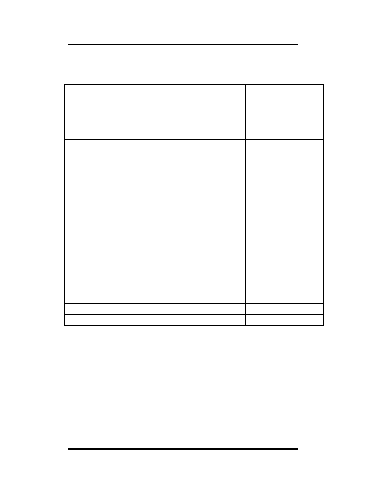
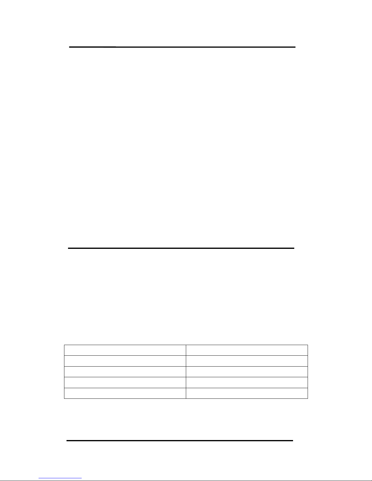
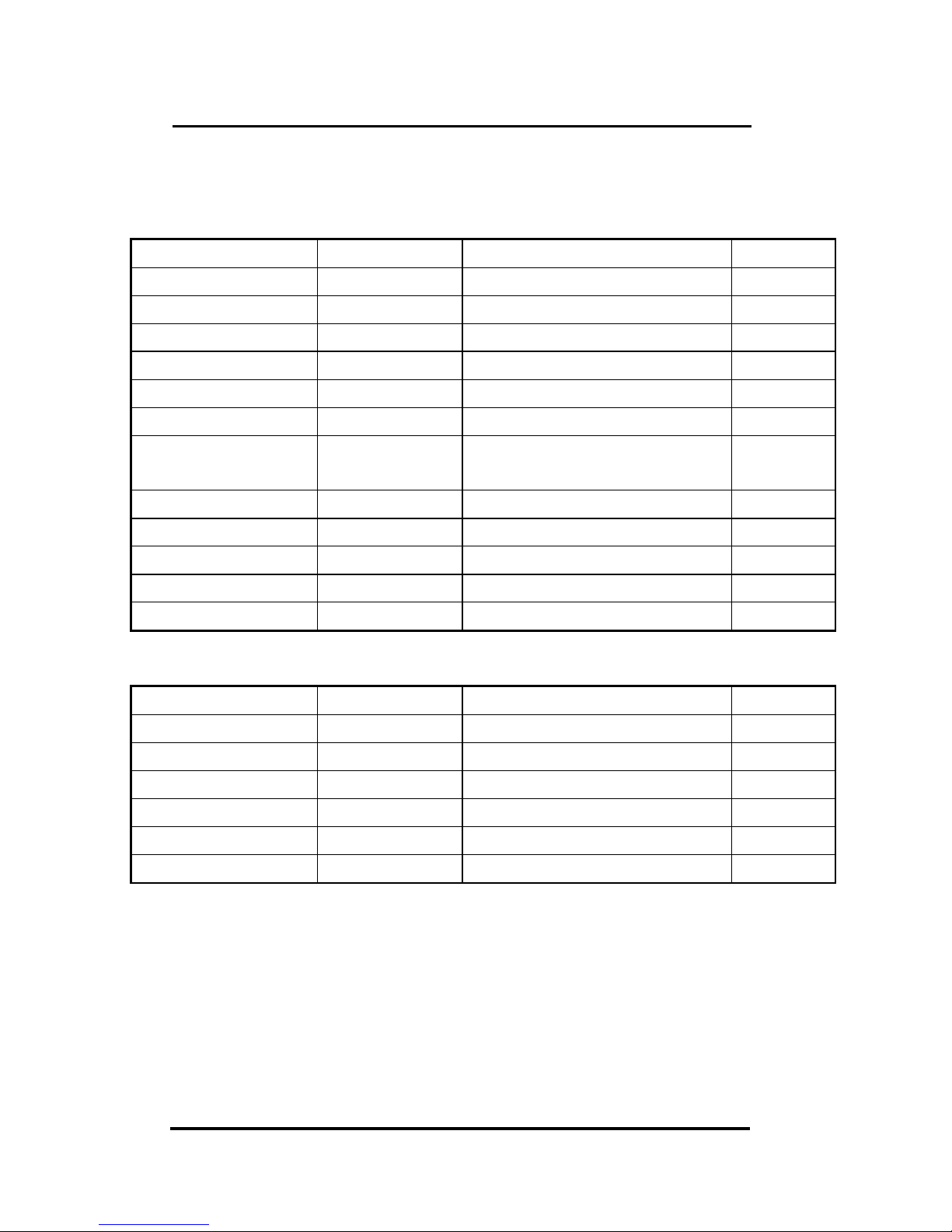
1.1 7080/7080D & 4080/4080D
Comparison between I-7080 & I-7080D
I-7080 I-7080D
5-digit LED No Yes
Response to LED
command
No Yes
Module name programmable programmable
Counter preset value Yes(programmable) Yes(programmable)
Alarm on counter 0 only Yes(programmable) Yes(programmable)
Alarm on counter 0&1 Yes(programmable) Yes(programmable)
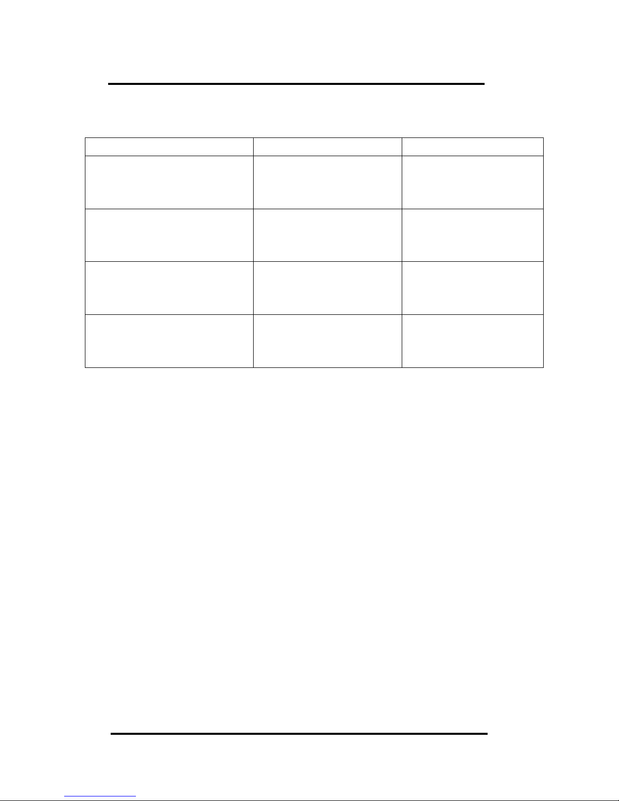
Channel 0 & channel 1 are
both non-isolated
(input mode 0, $AAB0)
Yes Yes
Channel 0 & channel 1 are
both isolated
(input mode 1, $AAB1)
Yes Yes
Channel 0 is non-isolated
& channel 1 is isolated
(input mode 2, $AAB2)
Yes Yes
Channel 0 is isolated &
channel 1 is non-isolated
(input mode 3, $AAB3)
Yes Yes
Input frequency 100K max. 100K max.
Default setting 4080 compatible 4080D compatible
default setting of I-7080:
High alarm on counter 0 & 1
Counter preset value: 0
Module name: 7080
default setting of I-7080D:
High/High-High alarm on counter 0
Counter preset value: 0
Module name: 7080D
Page 6
I-7080, I-7080D, I-7080B, I7080BD User Manual (V 2.2) ------------------ 6
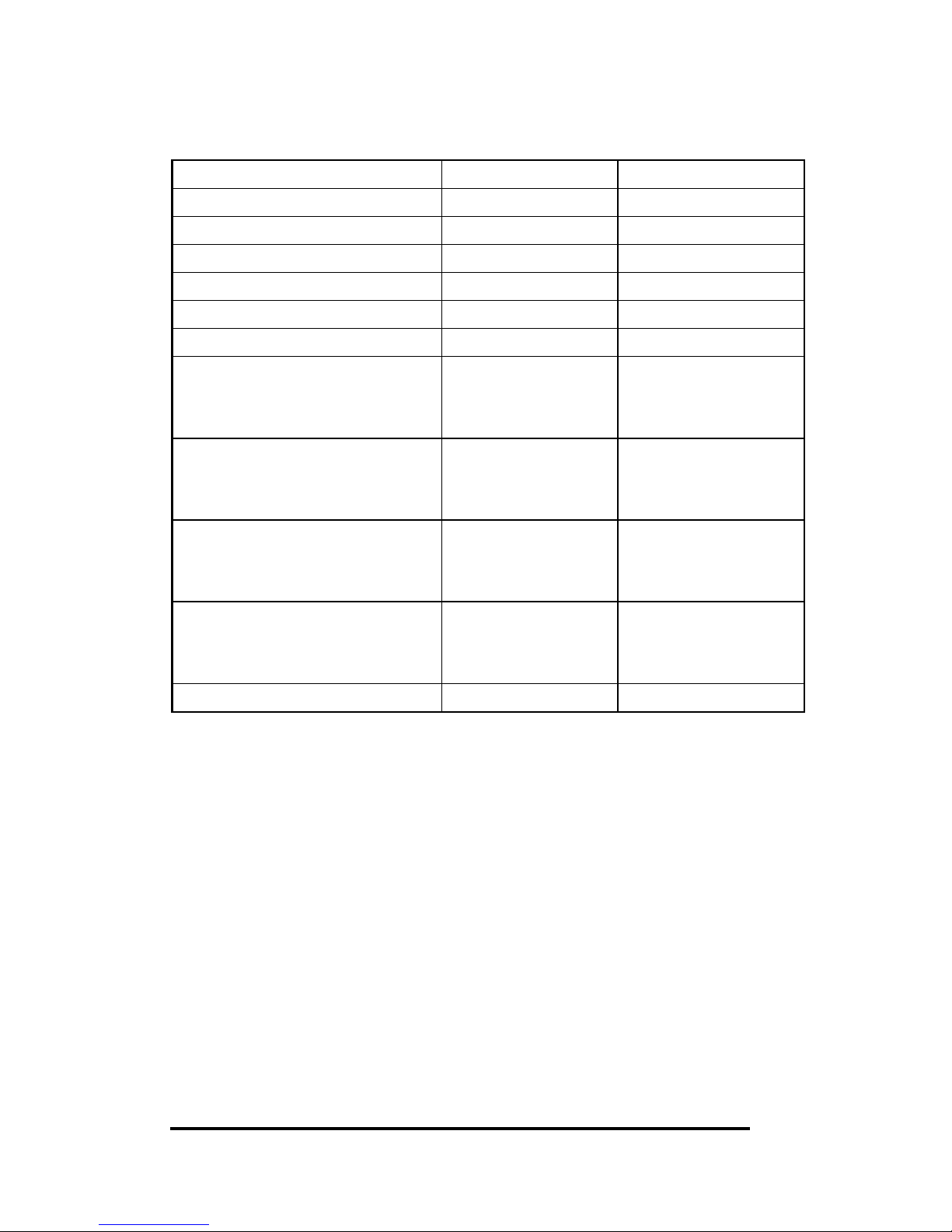
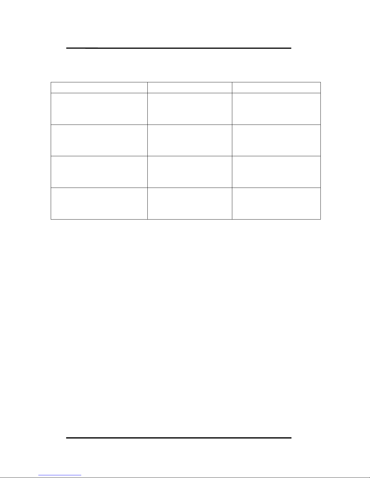
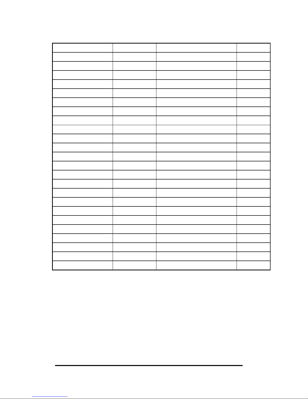
Comparison between 4080 & 4080D
4080 4080D
5-digit LED No Yes
Response to LED command No Yes
Module name 4080 4080D
Counter preset value Yes No
Alarm on counter 0 only No Yes
Alarm on counter 0&1 Yes No
Channel 0 & channel 1 are
both non-isolated
(input mode 0, $AAB0)
Yes Yes
Channel 0 & channel 1 are
both isolated
(input mode 1, $AAB1)
Yes Yes
Channel 0 is non-
isolated &
channel 0 is isolated
(input mode 2, $AAB2)
No No
Channel 0 is isolated &
channel 1 is non-isolated
(input mode 3, $AAB3)
No No
Input frequency 50K max. 50K max.
Page 7
I-7080, I-7080D, I-7080B, I7080BD User Manual (V 2.2) ------------------ 7
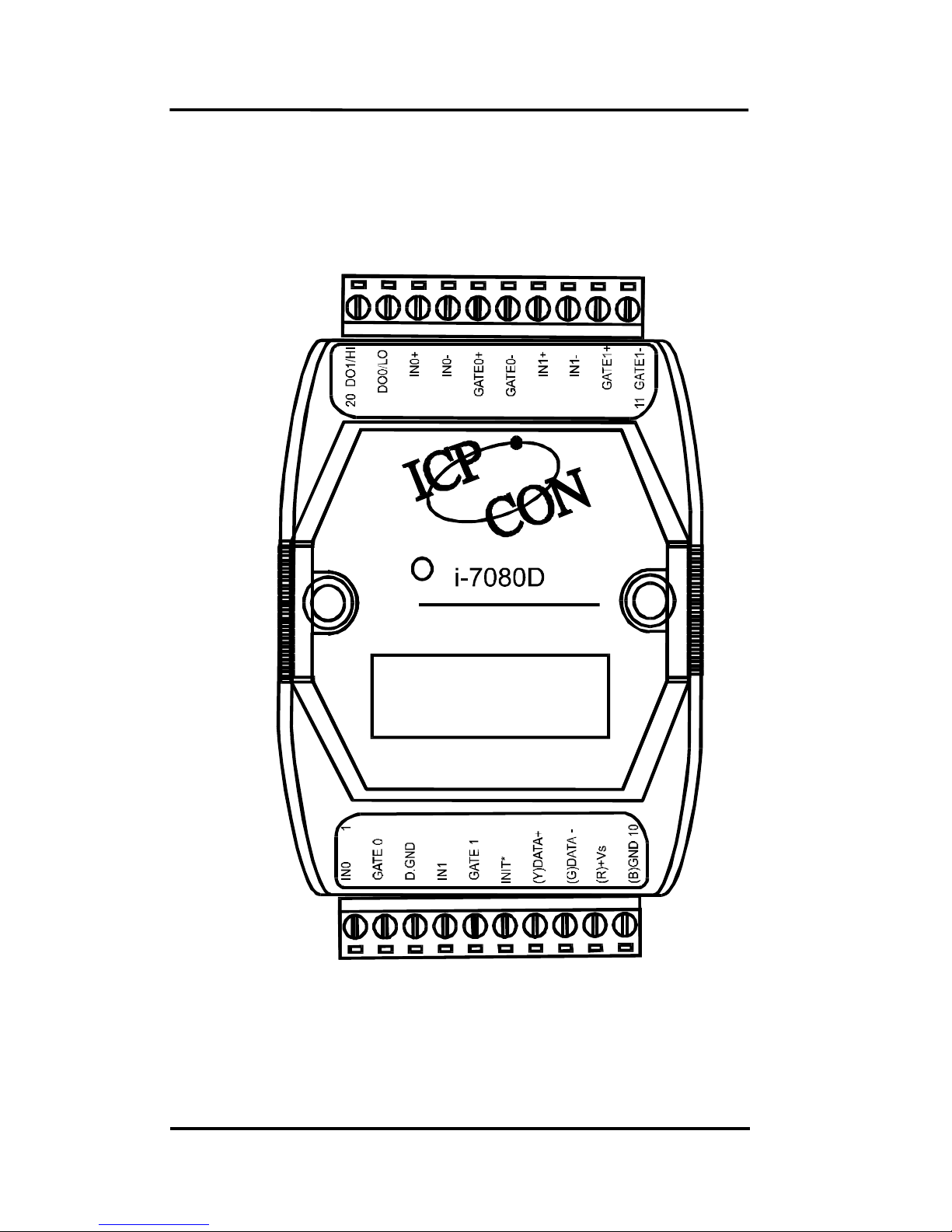
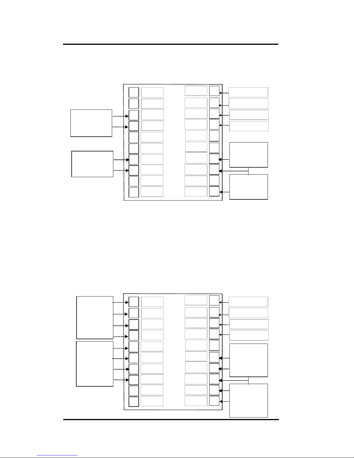
1.2 Pin Assignment
Non-isolated Input
Isolated Input
Page 8

I-7080, I-7080D, I-7080B, I7080BD User Manual (V 2.2) ------------------ 8
1.3 Specifications
i-7080: Counter/Frequency Module
i-7080D: i-7080 with LED Display
i-7080B: Refer to Sec. 3.3 for details.
i-7080BD: Refer to Sec. 3.3 for details.
Counter Input
Channels: Two independents 32 bit counters, counter 0&1
Input signal: Isolated or non-isolated programmable
Isolation input levels:
Logic level 0: +1V max.
Logic level 1: +3.5V to +30V
Isolation voltage: 3750 Vrms
non-isolation input threshold level: programmable
Logic level 0: 0 to +5V (default = 0.8V)
Logic level 1: 0 to +5V (default = 2.4V)
Maximum count: 32 bit (4,294,967,295)
Programmable digital noise filter: 2 us to 65 ms
Alarming: alarm on counter 0 or counter 0&1, programmable
Counter preset value: programmable
Display
LED Indicator: 5-digit readout, channel 0 or channel 1
Frequency Measurement
Input frequency: 1Hz to 100K Hz max.
Programmable built-in gate time: 1.0/0.1sec
Digital Output
2 channels, open-collector to 30V, 30mA max. load
Power dissipation: 300mW
Power
Power requirements:
I-7080/7080D: +10V to 30V(non-regulated)
I-7080B/7080BD: +24V to 30V(non-regulated)
Power consumption : 2W for I-7080, 2.2W for I-7080D
Page 9

I-7080, I-7080D, I-7080B, I7080BD User Manual (V 2.2) ------------------ 9
1.4 Block Diagram
Embedded
Controller
Programmable Digital Filter
EEPROM
RS-485
D+
D-
DC
DC
V+
V-
5V
0V
D/O
O.C.
Alarm
Output
5-digit LED (I-7080D)
5V
Counter_0
Counter_1
5V
Gate0+
Isolated/Non-isolated input selection
Isolated/Non-isolated gate selection
Gate0-
5V
Gate1+
Gate1-
In0+
In0-
In1+
In1-
Gate0(TTL)
Gate1(TTL)
In0(TTL)
In1(TTL)
Programmable threshold
voltage
Non
-
isolated input
Isolated input
5V
Save to
EEPROM
Voltage
Detect
For 7080B/7080BD only
Page 10
I-7080, I-7080D, I-7080B, I7080BD User Manual (V 2.2) ------------------ 10
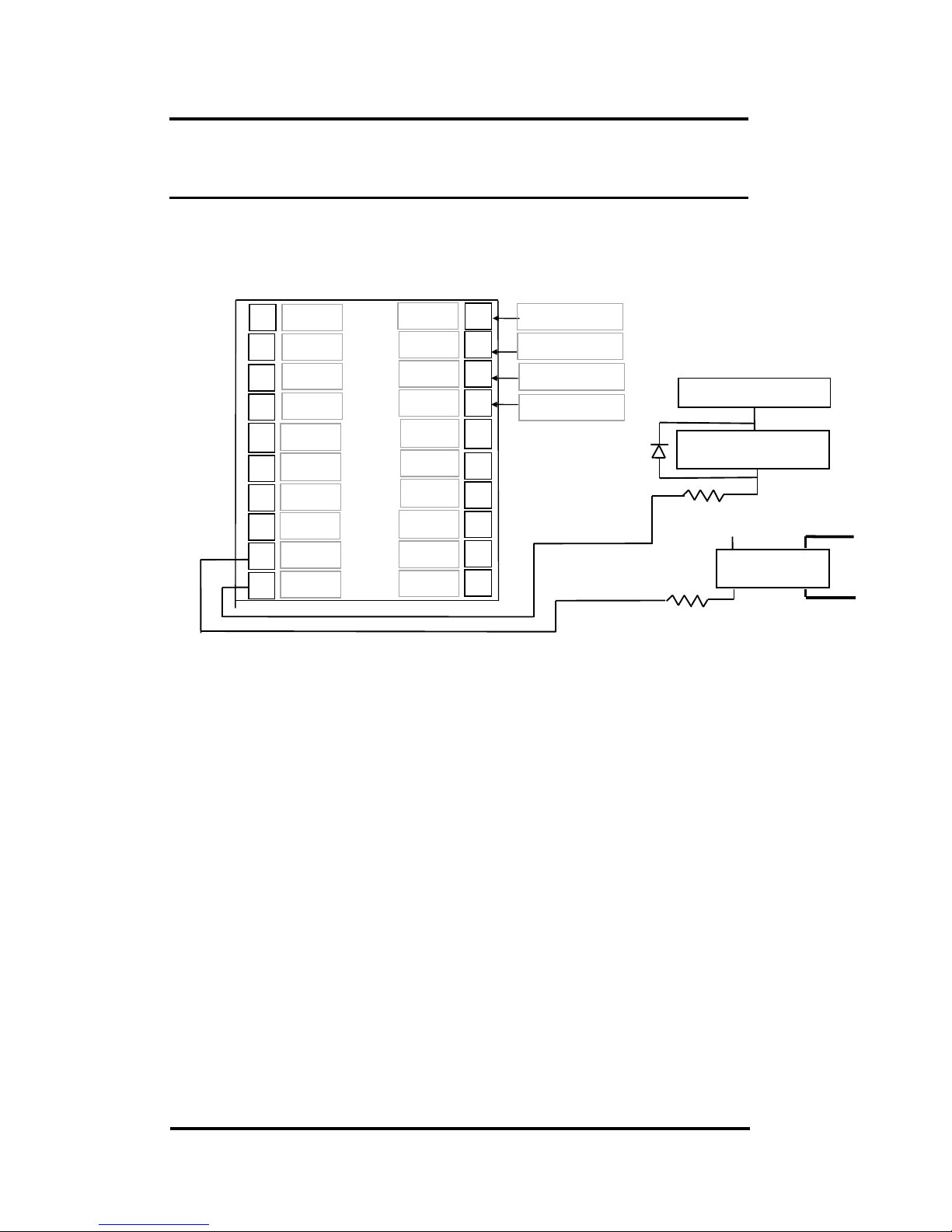
1.5 Application Wiring
1.5.1 Output Drive SSR or Other Load
Ext. GND
Ext. 24V
RS-485 Data
-
RS-485 Data
-
7
6
5
4
3
8
2
1
9
10 GND
+VS
Data+
Data
-
In0
D.Gnd
Gate0
Init*
12
11 Gate1
-
Gate1+
14
15
16
17
18
13
19
20
In1-
Do1/Hi
Do0/Lo
In0+
Gate1
In1
In1+
Gate0
-
Gate0+
In0-
SSR AC
+VS
R2
External Load
External Power
R1
1N4001
Note:
If the external load is resistive load, the 1N4001 can be omitted.
(transistor, lamp, resistor, …)
If the external load is inductive load, the 1N4001 can’t be omitted.
(relay, coil, …)
I-7018 & I
-
7018D
Page 11
I-7080, I-7080D, I-7080B, I7080BD User Manual (V 2.2) ------------------ 11
1.5.2 Frequency Input
Use $AABS command to select isolated/non-isolated input.
1.5.3 Counter Input
Ext. GND
Ext. 24V
RS-485 Data
-
RS-485 Data
-
7
6
5
4
3
8
2
1
9
10 GND
+VS
Data+
Data
-
In0
D.Gnd
Gate0
Init*
12
11 Gate1
-
Gate1+
14
15
16
17
18
13
19
20
In1-
Do1/Hi
Do0/Lo
In0+
Gate1
In1
In1+
Gate0
-
Gate0+
In0-
I-7018 & I-7018D
Frequency 0
(isolated)
Frequency-1
(non-iolated)
Frequency-0
(non-iolated)
Ext. GND
Ext. 24V
RS-485 Data
-
RS-485 Data
-
7
6
5
4
3
8
2
1
9
10
GND
+VS
Data+
Data
-
In0
D.Gnd
Gate0
Init*
12
11 Gate1
-
Gate1+
14
15
16
17
18
13
19
20
In1-
Do1/Hi
Do0/Lo
In0+
Gate1
In1
In1+
Gate0
-
Gate0+
In0-
I-7018 & I-7018D
Counter-1
& Gate-1
(isolated)
Counter-0
& Gate-0
(isolated)
Counter-1 &
Gate-1
(non-iolated)
Counter-0 &
Gate-0
(non-iolated)
Page 12

I-7080, I-7080D, I-7080B, I7080BD User Manual (V 2.2) ------------------ 12
1.6 Quick Start
Refer to “I-7000 Bus Converter User Manual” chapter-5 for
the following functions:
module status unknown(Sec. 5.1), change address(Sec. 5.2)
change baud rate(Sec. 5.3), checksum enable/disable(Sec. 5.4)
Wire connection(Sec 2.4)
Test program TEST.EXE(Refer to “NAP7000S User
Manual” for details.
1.6.1 Frequency Input Measurememt
1. Refer to Sec. 1.5.2 for wire connection. Power on and run test.exe
2. press 2
3. press $012[Enter] Receive=!01500600
4. press 2
5. press %0101510600[Enter] Receive=>!01
6. press 2
7. press $01B0[Enter] Receive=!01
8. press 2
9. press #010[Enter] Receive=>????????
10. press 2
11. press #011[Enter] Receive=>????????
step 3: the status of I-7080 is COUNTER mode
step 5: change to frequency mode
step 7: select non-isolated input
step 9: frequency measurement of channel-0
step 11: frequency measurement of channel-1
Note: the command $01B1(step 7) can be used to select the iso-
lated input.(the command $01B2 and $01B3 are used for
the other selections)
Page 13

I-7080, I-7080D, I-7080B, I7080BD User Manual (V 2.2) ------------------ 13
1.6.2 Counter input Measurement
1. Refer to Sec. 1.5.2 for wire connection. Power on and run test.exe
2. press 2
3. press $012[Enter] Receive=!01500600
4. press 2
5. press $01B0[Enter] Receive=!01
6. press 2
7. press #010[Enter] Receive=>????????
8. press 2
9. press #011[Enter] Receive=>????????
step 3: the status of I-7080 is COUNTER mode
step 5: select non-isolated input
step 7: counter measurement of channel-0
step 9: counter measurement of channel-1
Note: the command $01B1(step 7) can be used to select the iso-
lated input.(the command $01B2 and $01B3 are used for
the other selections)
Page 14
I-7080, I-7080D, I-7080B, I7080BD User Manual (V 2.2) ------------------ 14
1.7 Default Setting
The default setting is given as following:
address=01
baud rate=9600
checksum disable
data=1 start+8 data+1 stop(no parity)
type=50 counter input
alarm=hi alarm on counter 0 & counter 1 (I-7080)
hi/hi-hi alarm on counter 0 (I-7080D)
1.8 Application Notes
1.8.1 Counter/Frequency Input Mode Selection
The counter/frequency input can be selected from isolated
or non-isolated signal. The channel 0 & channel 1 can be
selected separately. There are 4 different input mode given as
following: These four input modes can be used in both of I-7080
& I-7080D.
Input Mode Command Channel 0 Channel 1
Input mode 0 $AAB0 Non-isolated Non-isolated
Input mode 1 $AAB1 Isolated Isolated
Input mode 2 $AAB2 Non-isolated Isolated
Input mode 3 $AAB3 Isolated Non-isolated
Page 15
I-7080, I-7080D, I-7080B, I7080BD User Manual (V 2.2) ------------------ 15
1.8.2 Counter Alarm Mode Selection
There are no alarm function in frequency mode(51). There
are two counter alarm mode, alarm mode 0 & alarm mode 1.
These two alarm modes can be used in both of I-7080 & I7080D.
The alarm mode 0 is designed for two-channel application
as following:
select alarm mode 0: ~AAA0 (for both channels)
enable channel 0: @AAEA0
disable channel 0: @AADA0
set high alarm limit of channel 0: @AAPA(data)
if (counter 0 >= alarm limit 0) D/O 0 turn ON
if (counter 0 < alarm limit 0) D/O 0 turn OFF
enable channel 1: @AAEA1
disable channel 1: @AADA1
set high alarm limit of channel 1: @AASA(data)
if (counter 1 >= alarm limit 1) D/O 1 turn ON
if (counter 1 < alarm limit 1) D/O 1 turn OFF
The alarm mode 1 is designed for single-channel
application as following:
select alarm mode 1: ~AAA1 (for channel 0 only)
enable channel 0: @AAEAT
disable channel 0: @AADA
clear latch alarm: @AACA
set high alarm limit: @AAPA(data)
set high-high alarm limit: @AASA(data)
D/O 0 D/O 1
Counter 0 < high alarm OFF OFF
high alarm <= counter 0 &
counter 0 < high-high alarm
ON OFF
High-high alarm <= counter 0 ON ON
Note: high-high alarm must greater than high-alarm
Page 16
I-7080, I-7080D, I-7080B, I7080BD User Manual (V 2.2) ------------------ 16
1.8.3 Digital Output Application Notes
The D/O0 & D/O1 can be used as D/O or alarm output as
following:
• can be used as D/O in the frequency mode.
• can be used as D/O in the counter mode & alarm disable
(by @AADA or @AADAN command)
• can be used as alarm output in the counter mode & alarm
enable(by @AAEAT or @AAEAN command)
D/O 0 D/O 1
Frequency mode D/O 0 D/O 1
Counter mode & alarm disable D/O 0 D/O 1
Counter mode & alarm enable (alarm
mode 1, ~AAA1)
High-alarm
on counter 0
High-high alarm
on counter 0
Counter mode & alarm enable (alarm
mode 0, ~AAA0 & @AAEA0)
Alarm on
counter 0
D/O 1 or alarm
on counter 1
Counter mode & alarm enable (alrm
mode 0, ~AAA0 & @AAEA1)
D/O 0 or
alarm on
counter 0
alarm on counter
1
1.8.4
Programmable Threshold Voltage Setting
The programmable threshold voltage is valid for non-
isolated input of counter mode (50) & frequency mode(51).
The default setting are given as following:
TTL compatible
low trigger level = 0.8 volt
high trigger level = 2.4 volt
The high trigger level can be changed by $AA1H(data)
command, the low trigger can be changed by $AA1L(data)
comand. The high trigger level must be greater than the low
trigger level.
Page 17

I-7080, I-7080D, I-7080B, I7080BD User Manual (V 2.2) ------------------ 17
1.8.5
Digital Filter Setting
The digital filter is disable in frequency mode(51). The
digital filter is designed as a pulse-width filter in both high/low
pulse. The digital filter is valid for both nono-isolated & isolated
input. The digital filter can be enable or disable. The key points
of using digital filter are given as following:
1. Use $AABS to select input signal.
2. Use $AA0H(data) to set min. width of high level.
3. Use $AA0L(data) to set min. width of low level.
4. Use $AA4S to enable/disbale digital filter (both channels).
If the high width of input signal is small than the min. high
width of digital filter, this input signal will be filtered out. Also
the low width of input signal must be greater than the min. low
width of digital filter.
For example, the width of input signal is greater than 1000
us, the user can set the digital filter at 900 us. Therefore all noise
below 900 us will be filtered out by the digital filter. These steps
are given as following:
1. $AAB0
2. $AA0H00900
3. $AA0L00900
4. $AA41
Page 18
I-7080, I-7080D, I-7080B, I7080BD User Manual (V 2.2) ------------------ 18
1.8.6
Gate Control Setting
The gate control will be ignored in frequency mode(51).
The gate control is defaultly disable in counter mode(50). The
user can use command to enable/disable the gate control as
following:
$AAA0 gate input must be low to enable counter
$AAA1 gate input must be high to enable counter
$AAA2 gate input is ignored. The counter will be
always enable.
1.8.7
Preset Value Setting
The preset value will be ignored in frequency mode(51).
The counters will go to their preset value in the first power-on
state. The reset counter command, $AA6N, also force the
counters go to their preset value. The factory default setting of
preset value is 0. The user can use the $AAPN(data) command
to change the preset value. The key points are given as
following:
I-7080 & I-7080D
Factory default setting Counter preset value is 0
Power on state Counter 0/1 go to preset value
$AA6N Counter N go to preset value
$AAPN(data) Set preset value of counter N
Page 19
I-7080, I-7080D, I-7080B, I7080BD User Manual (V 2.2) ------------------ 19
1.8.8 Frequency Input Applications
Type=51
Frequency 0 Frequency 1
$AAB0 input mode 0
$AA1H(data) &
$AA1L(data)
Non-isolated channel
0 & threshold value
active
Non-isolated channel
1 & threshold value
active
$AAB1 input mode 1
$AA1H(data) &
$AA1L(data)
Isolated channel 0 Isolated channel 1
$AAB2 input mode 2
$AA1H(data) &
$AA1L(data)
Non-isolated channel
0 & threshold value
active
Isolated channel 1
$AAB3 input mode 3
$AA1H(data) &
$AA1L(data)
Isolated channel 0 Non-isolated channel
1 & threshold value
active
The steps to measure frequency are given as following:
1. Use $AA1H(data) & $AA1L(data) to set the threshld value if
the frequency is non-isolated input.
2. Use $AAB? to select the mode (this command will clear the
current frequency first)
3. Use #AA? to perform frequency measurement
Note: Only four commands are important in frequency
measurement mode. These commands are given as following:
• $AAB? select mode
• $AA1H(data) set high-level threshold value
• $AA1L(data) set low_level threshold value
• #AA? perform frequency measurement
The status-read-back commands are given as following:
• $AAB mode read back
• $AA1H high_level threshold value read back
• $AA1L(data) low_level threshold value read back
Page 20
I-7080, I-7080D, I-7080B, I7080BD User Manual (V 2.2) ------------------ 20
1.8.9 Counter Input Applications
Tyepe=50
Counter 0 Counter 1
$AAB0 input mode 0
$AA1H(data) &
$AA1L(data)
Non-isolated channel
0 & threshold value
active
Non-isolated channel
1 & threshold value
active
$AAB1 input mode 1
$AA1H(data) &
$AA1L(data)
Isolated channel 0 Isolated channel 1
$AAB2 input mode 2
$AA1H(data) &
$AA1L(data)
Non-isolated channel
0 & threshold value
active
Isolated channel 1
$AAB3 input mode 3
$AA1H(data) &
$AA1L(data)
Isolated channel 0 Non-isolated channel
1 & threshold value
active
Note: the threshold value command, $AA1H(data) &
$AA1L(data) are effective to Non-isolated input only.
Page 21
I-7080, I-7080D, I-7080B, I7080BD User Manual (V 2.2) ------------------ 21
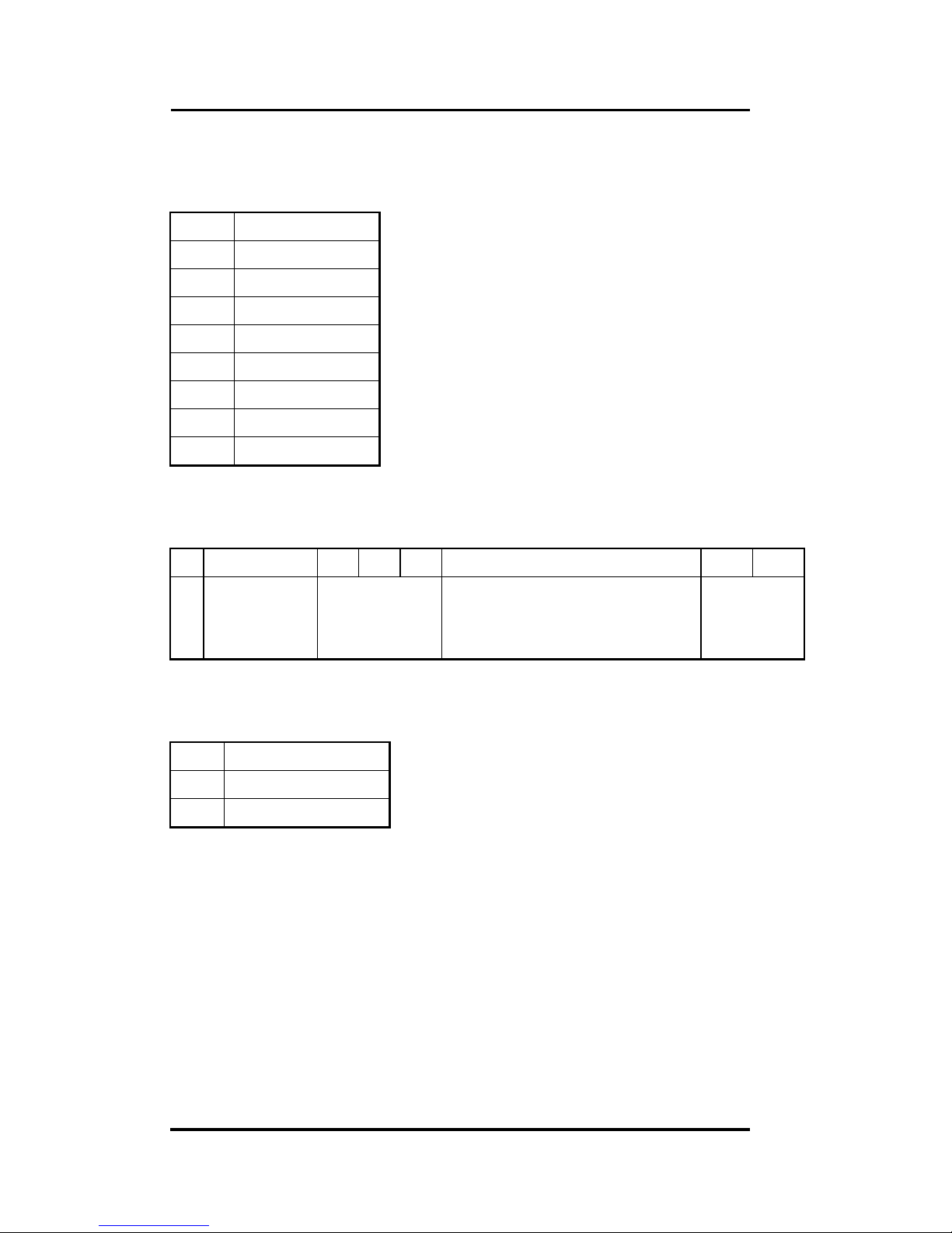
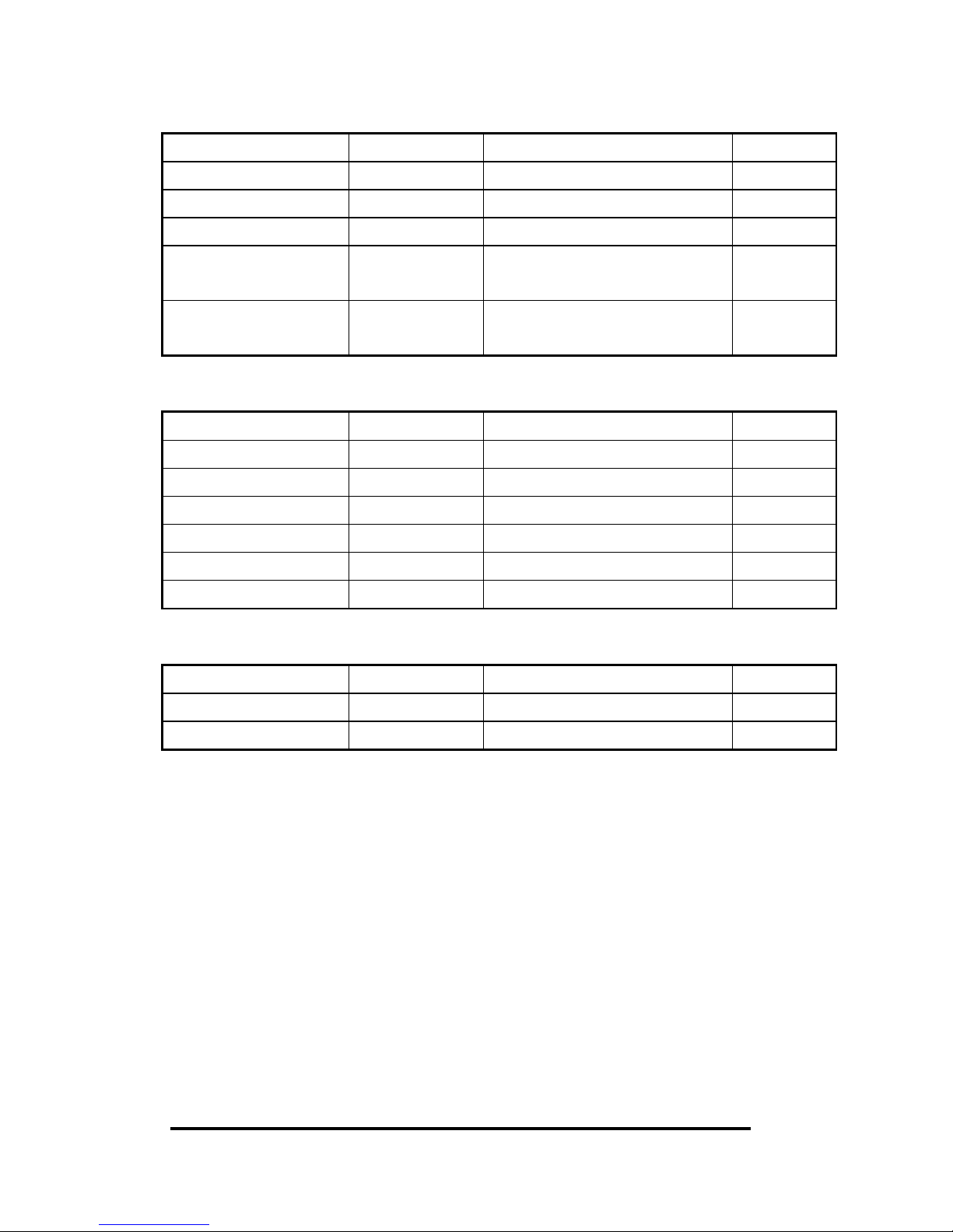
1.9 Tables
Configuration Code Table : CC
CC Baud Rate
03 1200 BPS
04 2400 BPS
05 4800 BPS
06 9600 BPS
07 19200 BPS
08 38400 BPS
09 57600 BPS
0A 115200 BPS
Configuration Code : FF, 2-char (for all)
7 6 5 4 3 2 1 0
0 checksum
0=disable
1=enable
0 frequency gate time
0: 0.1 second
1: 1.0 second
0
Configuration Code Table: TT
TT Input Range
50 Counter
51 Frequency
Page 22
I-7080, I-7080D, I-7080B, I7080BD User Manual (V 2.2) ------------------ 22
2. Command Set
General Command Set
Command Response Description Reference
%AANNTTCCFF !AA Set module configuration Sec. 2.1
#AAN >(data) Read counter or frequency Sec. 2.2
~** No Response Host OK Sec. 2.3
~AA0 !AASS Read Module Status Sec. 2.4
~AA1 !AA Reset Module Status Sec. 2.5
~AA2 !AATT Read Host Watchdog Timer Sec. 2.6
~AA3ETT !AA Enable Host Watchdog
Timer
Sec. 2.7
~AAO(name) !AA Set module name Sec. 2.9
$AA2 !AATTCCFF Read configuration Sec. 2.18
$AAF !AA(data) Read firmware number Sec. 2.34
$AAI !AAS Read the value of INIT* pin Sec. 2.35
$AAM !AA(data) Read the module name Sec. 2.36
Frequency Command Set
Command Response Description Reference
$AAB !AAS Read input mode Sec. 2.32
$AABS !AA Set input mode Sec. 2.33
$AA1H !AA(data) Read high trigger level Sec. 2.14
$AA1H(data) !AA Set high trigger level Sec. 2.15
$AA1L !AA(data) Read low trigger level Sec. 2.16
$AA1L(data) !AA Set low trigger level Sec. 2.17
Page 23
I-7080, I-7080D, I-7080B, I7080BD User Manual (V 2.2) ------------------ 23
General Counter Command Set
~AAAS !AA Set counter alarm mode Sec. 2.8
$AA0H !AA(data) Read min. width of High Sec. 2.10
$AA0H(data) !AA Set min. width of High Sec. 2.11
$AA0L !AA(data) Read min. width of High Sec. 2.12
$AA0L(data) !AA Set min. width of High Sec. 2.13
$AA1H !AA(data) Read high trigger level Sec. 2.14
$AA1H(data) !AA Set high trigger level Sec. 2.15
$AA1L !AA(data) Read low trigger level Sec. 2.16
$AA1L(data) !AA Set low trigger level Sec. 2.17
$AA3N !AA(data) Read max. counter value Sec. 2.19
$AA3N(data) !AA Set max. counter value Sec. 2.20
$AA4 !AAS Read filter status Sec. 2.21
$AA4S !AA Set filter status Sec. 2.22
$AA5N !AAS Read the counter status Sec. 2.23
$AA5NS !AA Set the counter status Sec. 2.24
$AA6N !AA Reset counter Sec. 2.25
$AA7N !AAS Read overflow status Sec. 2.26
$AAA !AAG Read gate mode Sec. 2.30
$AAAG !AA Set gate mode Sec. 2.31
$AAB !AAS Read input mode Sec. 2.32
$AABS !AA Set input mode Sec. 2.33
@AADI !AAS0D00 Read D/O & alarm state Sec. 2.37
@AADO0D !AA Set D/O value Sec. 2.38
@AAGN !AA(data) Read preset value Sec. 2.44
@AAPN(data) !AA Set preset value Sec. 2.45
Page 24
I-7080, I-7080D, I-7080B, I7080BD User Manual (V 2.2) ------------------ 24
Alarm-mode 0 Command Set
@AAEAN !AA Enable alarm Sec. 2.39
@AADAN !AA Disabel alarm Sec. 2.43
@AAPA(data) !AA Set counter 0 alarm value Sec. 2.46
@AASA(data) !AA Set counter 1 alarm value Sec. 2.48
@AARP !AA Read counter 0 alarm
value
Sec. 2.50
@AARA !AA Read counter 0 alarm
value
Sec. 2.52
Alarm-mode 1 Command Set
@AAEAT !AA Enable alarm Sec. 2.40
@AACA !AA Clear larch alarm Sec. 2.41
@AADA !AA Disabel alarm Sec. 2.42
@AAPA(data) !AA Set Hi-alarm value Sec. 2.47
@AASA(data) !AA Set Hi-Hi-alarm value Sec. 2.49
@AARP !AA Read Hi-alarm value Sec. 2.51
@AARA !AA Read Hi-Hi-alarm value Sec. 2.53
LED Command Set
$AA8 !AAS Read LED configuration Sec. 2.27
$AA8V !AA Set LED configuration Sec. 2.28
$AA9(data) !AA Send data to LED Sec. 2.29
Page 25

I-7080, I-7080D, I-7080B, I7080BD User Manual (V 2.2) ------------------ 25
2.1 %AANNTTCCFF
Description
: Set the configuration of module.
Syntax:
%AANNTTCCFF[chk](cr)
% is a delimiter character
AA=2-character HEX module address, from 00 to FF
NN=new AA
TT=input type code, refer to Sec. 1.9
CC=baud rate code, refer to Sec. 1.9
FF=status code, refer to Sec. 1.9
[chk]=2-character checksum, if checksum disable no [chk]
(cr)=0x0D
Response
: valid command !AA[chk](cr)
invalid command ?AA[chk](cr)
no response syntax error or communication
error or address error
! is a delimiter character indicating a valid command
? is a delimiter character indicating a invalid command
AA=2-character HEX module address
[chk]=2-character checksum, if checksum disable no [chk]
(cr)=0x0D
Example
:
command: %0102500600(cr)
response : !02(cr)
command: %0202510600(cr)
response : !02(cr)
Refer to “I-7000 Bus Converter User Manual” chapter-5
for the following functions:
module status unknown(Sec. 5.1), change address(Sec. 5.2)
change baud rate(Sec. 5.3), checksum enable/disable(Sec. 5.4)
address 01 is configured to a
new address 02, counter
Change to frequency mode
.
7080/7080D
Page 26

I-7080, I-7080D, I-7080B, I7080BD User Manual (V 2.2) ------------------ 26
2.2
#AAN
Description: Read counter or frequency value.
Syntax: #AAN[chk](cr)
# is a delimiter character
AA=2-character HEX module address, from 00 to FF
N=0 channel-0 of counter or frequency
1 channel-1 of counter or frequency
[chk]=2-character checksum, if checksum disable no [chk]
(cr)=0x0D
Response: valid command >[chk](data)(cr)
invalid command No Response
no response syntax error or communication
error or address error
> is a delimiter character indicating a valid command
(data) = 8-character data(in HEX format)
[chk]=2-character checksum, if checksum disable no [chk]
(cr)=0x0D
Example:
command: $012(cr)
response : !01500600(cr)
command: #010(cr)
response : >0000001E(cr)
command: $022(cr)
response : !02510600(cr)
command: #021(cr)
response : >0000001E(cr)
7080/7080D
Counter-0=0x1E=30 (in
decimal)
Frequency-
1=0x1E Hz = 30
Hz (in decimal)
Page 27

I-7080, I-7080D, I-7080B, I7080BD User Manual (V 2.2) ------------------ 27
2.3 ~**
Description
: Host send this command to tell all modules “Host is
OK”.
Syntax
: ~**[chk](cr)
~ is a delimiter character
[chk]=2-character checksum, if checksum disable no [chk]
(cr)=0x0D
Response
: no response
Example
:
command: ~**(cr)
response : No Response
7080/7080D
Page 28

I-7080, I-7080D, I-7080B, I7080BD User Manual (V 2.2) ------------------ 28
2.4 ~AA0
Description
: Read the module status. The module status will be
latched until ~AA1 command is sent. If the host watchdog is
enable and the host is down, the module status will be set to 4. If
the module status=4, all output command will be ignored.
Syntax
: ~AA0[chk](cr)
~ is a delimiter character
AA=2-character HEX module address, from 00 to FF
[chk]=2-character checksum, if checksum disable no [chk]
(cr)=0x0D
Response
: valid command !AASS[chk](cr)
invalid command ?AA[chk](cr)
no response syntax error or communication
error or address error
! is a delimiter character indicating a valid command
? is a delimiter character indicating a invalid command
AA=2-character HEX module address
SS=2-character HEX status value as following:
Bit_0, Bit_1 = reserved
Bit_2 = 0 OK,
1 host watchdog failure
[chk]=2-character checksum, if checksum disable no [chk]
(cr)=0x0D
Example
:
command: ~010(cr)
response : !0100(cr)
command: ~020(cr)
response : !0204(cr)
Status of module 01 is OK
Module status=04 host watchdog
failure HOST is down now
7080/7080D
Page 29

I-7080, I-7080D, I-7080B, I7080BD User Manual (V 2.2) ------------------ 29
2.5 ~AA1
Description
: Reset the module status. The module status will be
latched until ~AA1 command is sent. If the module status=4, all
output command will be ignored. Therefore the user should read
the module status first to make sure that the module status is 0. If
the module status is not 0, only ~AA1 command can clear the
module status.
Syntax
: ~AA1[chk](cr)
~ is a delimiter character
AA=2-character HEX module address, from 00 to FF
[chk]=2-character checksum, if checksum disable no [chk]
(cr)=0x0D
Response
: valid command !AA[chk](cr)
invalid command ?AA[chk](cr)
no response syntax error or communication
error or address error
! is a delimiter character indicating a valid command
? is a delimiter character indicating a invalid command
AA=2-character HEX module address
[chk]=2-character checksum, if checksum disable no [chk]
(cr)=0x0D
Example
:
command: ~010(cr)
response : !0104(cr)
command: @01DO00(cr )
response : !(cr)
command: ~011(cr)
response : !01(cr)
command: ~010(cr)
response : !0100(cr)
command: @01DO00(cr)
response : >(cr )
module status=0x04 host is down
clear module status
module status=0x00
Output command is ignored
Output command is OK
7080/7080D
Page 30

I-7080, I-7080D, I-7080B, I7080BD User Manual (V 2.2) ------------------ 30
2.6 ~AA2
Description
: Read the status and timer value of host watchdog.
The host watchdog timer is designed for host watchdog. When
the host watchdog is enable, the host must send ~** command to
all modules before the timer is up. When the ~** command is
received, the host watchdog timer is reset and restart. Use
~AA3ETT to enable/disable/setting the host watchdog timer.
Syntax
: ~AA2[chk](cr)
~ is a delimiter character
AA=2-character HEX module address, from 00 to FF
[chk]=2-character checksum, if checksum disable no [chk]
(cr)=0x0D
Response
: valid command !AASTT[chk](cr)
invalid command ?AA[chk](cr)
no response syntax error or communication
error or address error
! is a delimiter character indicating a valid command
? is a delimiter character indicating a invalid command
AA=2-character HEX module address
S=0: host watchdog is disable
S=1: host watchdog is enable
TT=2-character HEX value, from 00 to FF, unit=0.1 second
[chk]=2-character checksum, if checksum disable no [chk]
(cr)=0x0D
Example
:
command: ~012(cr)
response : !01000(cr)
command: ~022(cr)
response : !0210A(cr)
Host watchdog timer of
module 01 is disable
host watchdog timer of
module 02 is enable and =
0.1*10 = 1 second.
7080/7080D
Page 31

I-7080, I-7080D, I-7080B, I7080BD User Manual (V 2.2) ------------------ 31
2.7 ~AA3ETT
Description
: Enable/disable the timer value of host watchdog. The
host watchdog timer is designed for software host watchdog.
When the software host watchdog is enable, the host must send
~** command to all modules before the timer is up. When the
~** command is received, the host watchdog timer is reset and
restart. Use ~AA2 to read the host watchdog status & value.
Syntax
: ~AA3ETT[chk](cr)
~ is a delimiter character
AA=2-character HEX module address, from 00 to FF
E=0 is disable and 1 is enable
TT=2-character HEX value, from 00 to FF, unit=0.1 second
[chk]=2-character checksum, if checksum disable no [chk]
(cr)=0x0D
Response
: valid command !AA[chk](cr)
invalid command ?AA[chk](cr)
no response syntax error or communication
error or address error
! is a delimiter character indicating a valid command
? is a delimiter character indicating a invalid command
AA=2-character HEX module address
[chk]=2-character checksum, if checksum disable no [chk]
(cr)=0x0D
Example
:
command: ~013000(cr)
response : !01(cr)
command: ~02310A(cr)
response : !02(cr)
disable host watchdog timer
of module 01
host watchdog timer of
module 02 is enable and =
0.1*10 = 1 second.
7080/7080D
Page 32

I-7080, I-7080D, I-7080B, I7080BD User Manual (V 2.2) ------------------ 32
2.8
~
AAAS
Description
: Set counter alarm mode. Refer to Sec. 1.8.2 for more
information.
Syntax
: ~AAAS[chk](cr)
~ is a delimiter character
AA=2-character HEX module address, from 00 to FF
S=0 alarm mode 0.
1 alarm mode 1.
[chk]=2-character checksum, if checksum disable no [chk]
(cr)=0x0D
Response
: valid command !AA[chk](cr)
invalid command ?AA[chk](cr)
no response syntax error or communication
error or address error
! is a delimiter character indicating a valid command
? is a delimiter character indicating a invalid command
AA=2-character HEX module address
[chk]=2-character checksum, if checksum disable no [chk]
(cr)=0x0D
Example
:
command: ~01A0(cr)
response : !01(cr)
command: ~02A1(cr)
response : !02(cr)
Set alarm mode=0.
Set alarm mode=1.
7080/7080D
Page 33

I-7080, I-7080D, I-7080B, I7080BD User Manual (V 2.2) ------------------ 33
2.9 ~AAO(name)
Description
: Set module name.
Syntax
: ~AAO(name)[chk](cr)
~ is a delimiter character
AA=2-character HEX module address, from 00 to FF
(name)=4-character/5-character module name
[chk]=2-character checksum, if checksum disable no [chk]
(cr)=0x0D
Response
: valid command !AA[chk](cr)
invalid command ?AA[chk](cr)
no response syntax error or communication
error or address error
! is a delimiter character indicating a valid command
? is a delimiter character indicating a invalid command
AA=2-character HEX module address
[chk]=2-character checksum, if checksum disable no [chk]
(cr)=0x0D
Example
:
command: $01M(cr)
response : !017080(cr)
command: ~01O8080(cr)
response : !01(cr)
command: $01M(cr)
response : !017080D(cr)
command: ~01O8080D(cr)
response : !01(cr)
Note: This command is designed for OEM/ODM user. The user
can use it to change the module name for other purpose.
Change module name from
7080 to 8080
Change module name from
7080D to 8080D
7080/7080D
Page 34

I-7080, I-7080D, I-7080B, I7080BD User Manual (V 2.2) ------------------ 34
2.10 $AA0H
Description
: Read the min. input signal width at high level. Refer
to Sec. 1.8.5 for more information.
Syntax
: $AA0H[chk](cr)
$ is a delimiter character
AA=2-character HEX module address, from 00 to FF
[chk]=2-character checksum, if checksum disable no [chk]
(cr)=0x0D
Response
: valid command !AA(data)[chk](cr)
invalid command ?AA[chk](cr)
no response syntax error or communication
error or address error
! is a delimiter character indicating a valid command
? is a delimiter character indicating a invalid command
AA=2-character HEX module address
(data)=5-character decimal value for min. width at high level.
The unit is uS and the range can be from 2 uS to 65535 uS.
[chk]=2-character checksum, if checksum disable no [chk]
(cr)=0x0D
Example
:
command: $010H(cr)
response : !0100010(cr)
command: $020H(cr)
response : !0201000(cr)
7080/7080D
Min. width = 10 uS
Min. width = 1000 uS = 1 mS
Page 35

I-7080, I-7080D, I-7080B, I7080BD User Manual (V 2.2) ------------------ 35
2.11 $AA0H(data)
Description
: Set the min. input signal width at high level. Refer to
Sec. 1.8.5 for more information.
Syntax
: $AA0H(data)[chk](cr)
$ is a delimiter character
AA=2-character HEX module address, from 00 to FF
(data)=5-character decimal value for min. width at high level.
The unit is uS and the range can be from 2 uS to 65535
uS.
[chk]=2-character checksum, if checksum disable no [chk]
(cr)=0x0D
Response
: valid command !AA[chk](cr)
invalid command ?AA[chk](cr)
no response syntax error or communication error
or address error
! is a delimiter character indicating a valid command
? is a delimiter character indicating a invalid command
AA=2-character HEX module address
[chk]=2-character checksum, if checksum disable no [chk]
(cr)=0x0D
Example
:
command: $010H00010(cr)
response : !01(cr)
command: $020H01000(cr)
response : !02(cr)
7080/7080D
Min. width = 10 uS
Min. width = 1000 uS = 1 mS
Page 36

I-7080, I-7080D, I-7080B, I7080BD User Manual (V 2.2) ------------------ 36
2.12 $AA0L
Description
: Read the min. input signal width at low level. Refer
to Sec. 1.8.5 for more information.
Syntax
: $AA0L[chk](cr)
$ is a delimiter character
AA=2-character HEX module address, from 00 to FF
[chk]=2-character checksum, if checksum disable no [chk]
(cr)=0x0D
Response
: valid command !AA(data)[chk](cr)
invalid command ?AA[chk](cr)
no response syntax error or
communication error or address error
! is a delimiter character indicating a valid command
? is a delimiter character indicating a invalid command
AA=2-character HEX module address
(data)=5-character decimal value for min. width at low level. The
unit is uS and the range can be from 2 uS to 65535 uS.
[chk]=2-character checksum, if checksum disable no [chk]
(cr)=0x0D
Example
:
command: $010H(cr)
response : !0100020(cr)
command: $020H(cr)
response : !0202000(cr)
7080/7080D
Min. width=20 uS
Min. width=2000 uS=2 mS
Page 37

I-7080, I-7080D, I-7080B, I7080BD User Manual (V 2.2) ------------------ 37
2.13 $AA0L(data)
Description
: Set the min. input signal width at low level. Refer to
Sec. 1.8.5 for more information.
Syntax
: $AA0H(data)[chk](cr)
$ is a delimiter character
AA=2-character HEX module address, from 00 to FF
(data)=5-character decimal value for min. width at low level. The
unit is uS and the range can be from 2 uS to 65535 uS.
[chk]=2-character checksum, if checksum disable no [chk]
(cr)=0x0D
Response
: valid command !AA[chk](cr)
invalid command ?AA[chk](cr)
no response syntax error or communication
error or address error
! is a delimiter character indicating a valid command
? is a delimiter character indicating a invalid command
AA=2-character HEX module address
[chk]=2-character checksum, if checksum disable no [chk]
(cr)=0x0D
Example
:
command: $010H00020(cr)
response : !01(cr)
command: $020H02000(cr)
response : !02(cr)
7080/7080D
Min. width = 20 uS
Min. width = 2000 uS = 2 mS
Page 38

I-7080, I-7080D, I-7080B, I7080BD User Manual (V 2.2) ------------------ 38
2.14 $AA1H
Description
: Read the high trigger level of non-isolated input.
Refer to Sec. 1.8.4 for more information.
Syntax
: $AA1H[chk](cr)
$ is a delimiter character
AA=2-character HEX module address, from 00 to FF
[chk]=2-character checksum, if checksum disable no [chk]
(cr)=0x0D
Response
: valid command !AA(data)[chk](cr)
invalid command ?AA[chk](cr)
no response syntax error or communication
error or address error
! is a delimiter character indicating a valid command
? is a delimiter character indicating a invalid command
AA=2-character HEX module address
(data)=2-character decimal value for high trigger level. The unit
is 0.1 volt and the range can be from 0.0 to 5.0 volt.
[chk]=2-character checksum, if checksum disable no [chk]
(cr)=0x0D
Example
:
command: $011H(cr)
response : !0124(cr)
command: $021H(cr)
response : !0230(cr)
7080/7080D
High trigger level=2.4 volt
High trigger level=3.0 volt
Page 39

I-7080, I-7080D, I-7080B, I7080BD User Manual (V 2.2) ------------------ 39
2.15 $AA1H(data)
Description
: Set the high trigger level of non-isolated input. Refer
to Sec. 1.8.4 for more information.
Syntax
: $AA1H(data)[chk](cr)
$ is a delimiter character
AA=2-character HEX module address, from 00 to FF
(data)=2-character decimal value for high trigger level. The unit
is 0.1 volt and the range can be from 0.0 to 5.0 volt.
[chk]=2-character checksum, if checksum disable no [chk]
(cr)=0x0D
Response
: valid command !AA[chk](cr)
invalid command ?AA[chk](cr)
no response syntax error or communication
error or address error
! is a delimiter character indicating a valid command
? is a delimiter character indicating a invalid command
AA=2-character HEX module address
[chk]=2-character checksum, if checksum disable no [chk]
(cr)=0x0D
Example
:
command: $011H24(cr)
response : !01(cr)
command: $021H30(cr)
response : !02(cr)
Note
: default is 2.4V
7080/7080D
High trigger level=2.4 volt
High trigger level=3.0 volt
Page 40

I-7080, I-7080D, I-7080B, I7080BD User Manual (V 2.2) ------------------ 40
2.16 $AA1L
Description
: Read the Low trigger level of non-isolated input.
Refer to Sec. 1.8.4 for more information.
Syntax
: $AA1L[chk](cr)
$ is a delimiter character
AA=2-character HEX module address, from 00 to FF
[chk]=2-character checksum, if checksum disable no [chk]
(cr)=0x0D
Response
: valid command !AA(data)[chk](cr)
invalid command ?AA[chk](cr)
no response syntax error or communication
error or address error
! is a delimiter character indicating a valid command
? is a delimiter character indicating a invalid command
AA=2-character HEX module address
(data)=2-character decimal value for low trigger level. The unit is
0.1 volt and the range can be from 0.0 to 5.0 volt.
[chk]=2-character checksum, if checksum disable no [chk]
(cr)=0x0D
Example
:
command: $011L(cr)
response : !0108(cr)
command: $021L(cr)
response : !0210(cr)
7080/7080D
Low trigger level=0.8 volt
Low trigger level=1.0 volt
Page 41

I-7080, I-7080D, I-7080B, I7080BD User Manual (V 2.2) ------------------ 41
2.17 $AA1L(data)
Description
: Set the low trigger level of non-isolated input. Refer
to Sec. 1.8.4 for more information.
Syntax
: $AA1L(data)[chk](cr)
$ is a delimiter character
AA=2-character HEX module address, from 00 to FF
(data)=2-character decimal value for low trigger level. The unit is
0.1 volt and the range can be from 0.0 to 5.0 volt.
[chk]=2-character checksum, if checksum disable no [chk]
(cr)=0x0D
Response
: valid command !AA[chk](cr)
invalid command ?AA[chk](cr)
no response syntax error or communication
error or address error
! is a delimiter character indicating a valid command
? is a delimiter character indicating a invalid command
AA=2-character HEX module address
[chk]=2-character checksum, if checksum disable no [chk]
(cr)=0x0D
Example
:
command: $011L08(cr)
response : !01(cr)
command: $021L10(cr)
response : !02(cr)
Note
: default is 0.8V
7080/7080D
Low trigger level=0.8 volt
Low trigger level=1.0 volt
Page 42

I-7080, I-7080D, I-7080B, I7080BD User Manual (V 2.2) ------------------ 42
2.18 $AA2
Description
: Read the configuration of module.
Syntax
: $AA2[chk](cr)
$ is a delimiter character
AA=2-character HEX module address, from 00 to FF
[chk]=2-character checksum, if checksum disable no [chk]
(cr)=0x0D
Response
: valid command !AATTCCFF[chk](cr),
invalid command ?AA[chk](cr)
no response syntax error or communication
error or address error
! is a delimiter character indicating a valid command
? is a delimiter character indicating a invalid command
AA=2-character HEX module address
TT, CC, FF: refer to Sec. 1.9
[chk]=2-character checksum, if checksum disable no [chk]
(cr)=0x0D
Example
:
command: $012(cr)
response : !01500600(cr)
command: $022(cr)
response : !02510700(cr)
NOTE: If the user use %AANNTTCCFF command to change module
configuration, the new configuration code will be stored into
EEPROM immediately. The configuration code includes module
address, module type, baud rate code, checksum enable/disable code,
calibration code, power-on value and safe value. The EEPROM data
of I-7000 can be read infinite times and can be written about
100,000 times max. Therefore the user should not change
configuration code often for testing.
The $AA2 command is used to read EEPROM data only, therefore the
user can send this command to I-7000 module infinitely.
Address=01, counter, 9600 BPS,
checksum disable
Address=02, frequency, 19200 BPS,
checksum disable
7080/7080D
Page 43

I-7080, I-7080D, I-7080B, I7080BD User Manual (V 2.2) ------------------ 43
2.19 $AA3N
Description
: Read the max. counter value.
Syntax
: $AA3N[chk](cr)
$ is a delimiter character
AA=2-character HEX module address, from 00 to FF
N=0 channel-0 of counter or frequency
1 channel-1 of counter or frequency
[chk]=2-character checksum, if checksum disable no [chk]
(cr)=0x0D
Response
: valid command !AA(data)[chk](cr)
invalid command ?AA[chk](cr)
no response syntax error or
communication error or address error
! is a delimiter character indicating a valid command
? is a delimiter character indicating a invalid command
AA=2-character HEX module address
(data)=8-character HEX value.
[chk]=2-character checksum, if checksum disable no [chk]
(cr)=0x0D
Example
:
command: $0130(cr)
response : !010000FFFF(cr)
command: $0131(cr)
response : !01FFFFFFFF(cr)
7080/7080D
Counter-
0 from preset value
to FFFF
Counter-
1 from preset value
to FFFFFFFF
Page 44

I-7080, I-7080D, I-7080B, I7080BD User Manual (V 2.2) ------------------ 44
2.20 $AA3N(data)
Description
: Set the max. counter value.
Syntax
: $AA3N(data)[chk](cr)
$ is a delimiter character
AA=2-character HEX module address, from 00 to FF
N=0 channel-0 of counter or frequency
1 channel-1 of counter or frequency
(data)=8-character HEX value.
[chk]=2-character checksum, if checksum disable no [chk]
(cr)=0x0D
Response
: valid command !AA(data)[chk](cr)
invalid command ?AA[chk](cr)
no response syntax error or communication
error or address error
! is a delimiter character indicating a valid command
? is a delimiter character indicating a invalid command
AA=2-character HEX module address
[chk]=2-character checksum, if checksum disable no [chk]
(cr)=0x0D
Example
:
command: $01300000FFFF(cr)
response : !01(cr)
command: $0131FFFFFFFF(cr)
response : !01(cr)
7080/7080D
Counter-
0 from preset value
to FFFF
Counter-
1 from preset value
to FFFFFFFF
Page 45

I-7080, I-7080D, I-7080B, I7080BD User Manual (V 2.2) ------------------ 45
2.21 $AA4
Description
: Read the status of digital filter. Refer to Sec. 1.8.5 for
more information.
Syntax
: $AA4[chk](cr)
$ is a delimiter character
AA=2-character HEX module address, from 00 to FF
[chk]=2-character checksum, if checksum disable no [chk]
(cr)=0x0D
Response
: valid command !AAS[chk](cr)
invalid command ?AA[chk](cr)
no response syntax error or communication
error or address error
! is a delimiter character indicating a valid command
? is a delimiter character indicating a invalid command
AA=2-character HEX module address
S=0 digital filter is disable
1 digital filter is enable
[chk]=2-character checksum, if checksum disable no [chk]
(cr)=0x0D
Example
:
command: $014(cr)
response : !010(cr)
command: $024(cr)
response : !021(cr)
Digital filter is disable.
Digital filter is enable.
7080/7080D
Page 46

I-7080, I-7080D, I-7080B, I7080BD User Manual (V 2.2) ------------------ 46
2.22 $AA4S
Description
: Set the filter status. Refer to Sec. 1.8.5 for more
information.
Syntax
: $AA4S[chk](cr)
$ is a delimiter character
AA=2-character HEX module address, from 00 to FF
S=0 digital filter is disable
1 digital filter is enable
[chk]=2-character checksum, if checksum disable no [chk]
(cr)=0x0D
Response
: valid command !AA[chk](cr)
invalid command ?AA[chk](cr)
no response syntax error or communication
error or address error
! is a delimiter character indicating a valid command
? is a delimiter character indicating a invalid command
AA=2-character HEX module address
[chk]=2-character checksum, if checksum disable no [chk]
(cr)=0x0D
Example
:
command: $0140(cr)
response : !01(cr)
command: $0241(cr)
response : !02(cr)
Digital filter is disable.
Digital filter is enable.
7080/7080D
Page 47

I-7080, I-7080D, I-7080B, I7080BD User Manual (V 2.2) ------------------ 47
2.23 $AA5N
Description
: Read the counter status
Syntax
: $AA5N[chk](cr)
$ is a delimiter character
AA=2-character HEX module address, from 00 to FF
N=0 counter 0
1 counter 1
[chk]=2-character checksum, if checksum disable no [chk]
(cr)=0x0D
Response
: valid command !AAS[chk](cr)
invalid command ?AA[chk](cr)
no response syntax error or communication
error or address error
! is a delimiter character indicating a valid command
? is a delimiter character indicating a invalid command
AA=2-character HEX module address
S=0 counter is stop (disable)
1 counter is start (enable)
[chk]=2-character checksum, if checksum disable no [chk]
(cr)=0x0D
Example
:
command: $0150(cr)
response : !010(cr)
command: $0151(cr)
response : !011(cr)
Counter 0 is stop now.
Counter 1 is start now.
7080/7080D
Page 48

I-7080, I-7080D, I-7080B, I7080BD User Manual (V 2.2) ------------------ 48
2.24 $AA5NS
Description
: Set the counter status
Syntax
: $AA5NS[chk](cr)
$ is a delimiter character
AA=2-character HEX module address, from 00 to FF
N=0 counter 0
1 counter 1
S=0 stop counter
1 start counter
[chk]=2-character checksum, if checksum disable no [chk]
(cr)=0x0D
Response
: valid command !AA[chk](cr)
invalid command ?AA[chk](cr)
no response syntax error or communication
error or address error
! is a delimiter character indicating a valid command
? is a delimiter character indicating a invalid command
AA=2-character HEX module address
[chk]=2-character checksum, if checksum disable no [chk]
(cr)=0x0D
Example
:
command: $01500(cr)
response : !01(cr)
command: $01511(cr)
response : !01(cr)
Stop the counter 0.
Start the counter 1.
7080/7080D
Page 49

I-7080, I-7080D, I-7080B, I7080BD User Manual (V 2.2) ------------------ 49
2.25 $AA6N
Description
: Reset counter 0 or counter 1 to the preset value & clear
the overflow flag. Refer to Sec. 1.8.7 for more information.
Syntax
: $AA6N[chk](cr)
$ is a delimiter character
AA=2-character HEX module address, from 00 to FF
N=0 counter 0
1 counter 1
[chk]=2-character checksum, if checksum disable no [chk]
(cr)=0x0D
Response
: valid command !AA[chk](cr)
invalid command ?AA[chk](cr)
no response syntax error or communication
error or address error
! is a delimiter character indicating a valid command
? is a delimiter character indicating a invalid command
AA=2-character HEX module address
[chk]=2-character checksum, if checksum disable no [chk]
(cr)=0x0D
Example
:
command: @01G0(cr)
response : !0100000000(cr)
command: $0160(cr)
response : !01(cr)
command: @01G1(cr)
response : !010000ABCD(cr)
command: $0161(cr)
response : !01(cr)
Preset value=0
Reset counter 0 to pres
et value
0
7080/7080D
Preset value=0xABCD
Reset counter 1 to preset value
0xABCD
Page 50

I-7080, I-7080D, I-7080B, I7080BD User Manual (V 2.2) ------------------ 50
2.26 $AA7N
Description
: Read the overflow flag of counter. The user can use
$AA6S comand to reset counter & clear overflow flag.
Syntax
: $AA7N[chk](cr)
$ is a delimiter character
AA=2-character HEX module address, from 00 to FF
N=0 counter 0
1 counter 1
[chk]=2-character checksum, if checksum disable no [chk]
(cr)=0x0D
Response
: valid command !AAS[chk](cr)
invalid command ?AA[chk](cr)
no response syntax error or communication
error or address error
! is a delimiter character indicating a valid command
? is a delimiter character indicating a invalid command
AA=2-character HEX module address
S=0 no overflow
1 is overflow
[chk]=2-character checksum, if checksum disable no [chk]
(cr)=0x0D
Example
:
command: $0170(cr)
response : !011(cr)
command: $0160(cr)
response : !01(cr)
command: $0171(cr)
response : !010(cr)
Counter 0 is overflow.
Clear the overflow flag.
Counter 1 is OK.
7080/7080D
Page 51

I-7080, I-7080D, I-7080B, I7080BD User Manual (V 2.2) ------------------ 51
2.27 $AA8
Description
: Read the LED configuration.
Syntax
: $AA8[chk](cr)
$ is a delimiter character
AA=2-character HEX module address, from 00 to FF
[chk]=2-character checksum, if checksum disable no [chk]
(cr)=0x0D
Response
: valid command !AAS[chk](cr)
invalid command ?AA[chk](cr)
no response syntax error or communication
error or address error
! is a delimiter character indicating a valid command
? is a delimiter character indicating a invalid command
AA=2-character HEX module address
S=0 show counter/frequency channel 0
1 show counter/frequency channel 1
2 HOST control
[chk]=2-character checksum, if checksum disable no [chk]
(cr)=0x0D
Example
:
command: $018(cr)
response : !010(cr)
command: $028(cr)
response : !021(cr)
command: $038(cr)
response : !032 (cr)
LED show the value of channel 0.
LED show the value of channel 1.
7080D
HOST control the LED display.
Page 52

I-7080, I-7080D, I-7080B, I7080BD User Manual (V 2.2) ------------------ 52
2.28 $AA8V
Description: Select LED Configuration.
Syntax: $AA8V[chk](cr)
$ is a delimiter character
AA=2-character HEX module address, from 00 to FF
V=0 LED shows counter/frequency channel 0
1 LED show counter/frequency channel 1
….2 HOST control LED
[chk]=2-character checksum, if checksum disable no [chk]
(cr)=0x0D
Response: valid command !AA[chk](cr)
invalid command ?AA[chk](cr)
no response syntax error or
communication error or address error
! is a delimiter character indicating a valid command
? is a delimiter character indicating a invalid command
AA=2-character HEX module address
[chk]=2-character checksum, if checksum disable no [chk]
(cr)=0x0D
Example:
command: $0181(cr)
response : !01(cr)
command: $0282(cr)
response : !02(cr)
command: $029040.00(cr)
response : !02(cr)
LED shows channel 1.
HOST will control LED.
7080D
Page 53

I-7080, I-7080D, I-7080B, I7080BD User Manual (V 2.2) ------------------ 53
2.29 $AA9(data)
Description: Send data to LED display.
Syntax: $AA9(data)[chk](cr)
$ is a delimiter character
AA=2-character HEX module address, from 00 to FF
(data) 5 decimal digit + 1 decimal point
max. = 99999.
min. = 0.0000
[chk]=2-character checksum, if checksum disable no [chk]
(cr)=0x0D
Response: valid command !AA[chk](cr)
invalid command ?AA[chk](cr)
no response syntax error or
communication error or address error
! is a delimiter character indicating a valid command
? is a delimiter character indicating a invalid command
AA=2-character HEX module address
[chk]=2-character checksum, if checksum disable no [chk]
(cr)=0x0D
Example:
command: $01999999.(cr)
response : !01(cr)
command: $0290.0000(cr)
response : !02(cr)
command: $03912.345(cr)
response : !03(cr)
Show max. = 99999.
Show min. = 0.0000.
Show display = 12.345
7080D
Page 54

I-7080, I-7080D, I-7080B, I7080BD User Manual (V 2.2) ------------------ 54
2.30
$AAA
Description
: Read gate control mode. Refer to Sec. 1.8.6 for more
information.
Syntax
: $AAA[chk](cr)
$ is a delimiter character
AA=2-character HEX module address, from 00 to FF
[chk]=2-character checksum, if checksum disable no [chk]
(cr)=0x0D
Response
: valid command !AAG[chk](cr)
invalid command ?AA[chk](cr)
no response syntax error or communication
error or address error
! is a delimiter character indicating a valid command
? is a delimiter character indicating a invalid command
AA=2-character HEX module address
G=0 gate is low active
1 gate is high active
2 gate is disable
[chk]=2-character checksum, if checksum disable no [chk]
(cr)=0x0D
Example
:
command: $01A(cr)
response : !010(cr)
command: $02A(cr)
response : !021(cr)
command: $03A(cr)
response : !032 (cr)
Gate is low active.
Gate is high active.
7080/7080D
Gate is disable (always active).
Page 55

I-7080, I-7080D, I-7080B, I7080BD User Manual (V 2.2) ------------------ 55
2.31 $AAAG
Description
: Set gate control mode. Refer to Sec. 1.8.6 for more
information.
Syntax
: $AAAG[chk](cr)
$ is a delimiter character
AA=2-character HEX module address, from 00 to FF
G=0 gate is low active
1 gate is high active
2 gate is disable
[chk]=2-character checksum, if checksum disable no [chk]
(cr)=0x0D
Response
: valid command !AA[chk](cr)
invalid command ?AA[chk](cr)
no response syntax error or communication
error or address error
! is a delimiter character indicating a valid command
? is a delimiter character indicating a invalid command
AA=2-character HEX module address
[chk]=2-character checksum, if checksum disable no [chk]
(cr)=0x0D
Example
:
command: $01A0(cr)
response : !01(cr)
command: $02A1(cr)
response : !02(cr)
command: $03A2(cr)
response : !03(cr)
Gate is low active.
Gate is high active.
7080/7080D
Gate is disable (always active).
Page 56

I-7080, I-7080D, I-7080B, I7080BD User Manual (V 2.2) ------------------ 56
2.32 $AAB
Description
: Read input mode. Refer to Sec. 1.8.1 for more
information.
Syntax
: $AAB[chk](cr)
$ is a delimiter character
AA=2-character HEX module address, from 00 to FF
[chk]=2-character checksum, if checksum disable no [chk]
(cr)=0x0D
Response
: valid command !AAS[chk](cr)
invalid command ?AA[chk](cr)
no response syntax error or communication
error or address error
! is a delimiter character indicating a valid command
? is a delimiter character indicating a invalid command
AA=2-character HEX module address
S=0 channel 0 is non-isolated, channel 1 is non-isolated.
1 channel 0 is isolated, channel 1 is isolated.
2 channel 0 is non-isolated, channel 1 is isolated.
3 channel 0 is isolated, channel 1 is non-isolated.
[chk]=2-character checksum, if checksum disable no [chk]
(cr)=0x0D
Example
:
command: $01B(cr)
response : !010(cr)
command: $02B(cr)
response : !021(cr)
command: $03B(cr)
response : !032(cr)
Counter/frequency channel 0 is non-
isolated, channel
1 is non
-
isolated.
Counter/frequency channel 0 is
isolated, channel 1 is isolated.
7080/7080D
Counter/frequency channel 0 is non-
isolated, channel 1 is isolated.
Page 57

I-7080, I-7080D, I-7080B, I7080BD User Manual (V 2.2) ------------------ 57
2.33 $AABS
Description
: Set input mode. Refer to Sec. 1.8.1 for more
information.
Syntax
: $AABS[chk](cr)
$ is a delimiter character
AA=2-character HEX module address, from 00 to FF
S=0 channel 0 is non-isolated, channel 1 is non-isolated.
1 channel 0 is isolated, channel 1 is isolated.
2 channel 0 is non-isolated, channel 1 is isolated.
3 channel 0 is isolated, channel 1 is non-isolated.
[chk]=2-character checksum, if checksum disable no [chk]
(cr)=0x0D
Response
: valid command !AA[chk](cr)
invalid command ?AA[chk](cr)
no response syntax error or communication
error or address error
! is a delimiter character indicating a valid command
? is a delimiter character indicating a invalid command
AA=2-character HEX module address
[chk]=2-character checksum, if checksum disable no [chk]
(cr)=0x0D
Example
:
command: $01B0(cr)
response : !01(cr)
command: $02B1(cr)
response : !02(cr)
command: $03B2(cr)
response : !03(cr)
Counter/frequency channel 0 is non-
isolated, channel 1 is non
-
isolated.
Counter/frequency channel 0 is
isolated, channel 1 is isolated.
7080/7080D
Counter/frequency channel 0 is non-
isolated, channel 1 is isolated.
Page 58

I-7080, I-7080D, I-7080B, I7080BD User Manual (V 2.2) ------------------ 58
2.34 $AAF
Description
: Read the version number of firmware.
Syntax
: $AAF[chk](cr)
$ is a delimiter character
AA=2-character HEX module address, from 00 to FF
[chk]=2-character checksum, if checksum disable no [chk]
(cr)=0x0D
Response
: valid command !AA(data)[chk](cr)
invalid command ?AA[chk](cr)
no response syntax error or communication
error or address error
! is a delimiter character indicating a valid command
? is a delimiter character indicating a invalid command
AA=2-character HEX module address
data=5-character for version number
[chk]=2-character checksum, if checksum disable no [chk]
(cr)=0x0D
Example
:
command: $01F(cr)
response : !01A2.0(cr)
command: $02F(cr)
response : !02A3.0(cr)
Ver. A2.0
Ver. A3.0
7080/7080D
Page 59

I-7080, I-7080D, I-7080B, I7080BD User Manual (V 2.2) ------------------ 59
2.35 $AAI
Description
: Read the value of *INIT pin.
Syntax
: $AAI[chk](cr)
$ is a delimiter character
AA=2-character HEX module address, from 00 to FF
[chk]=2-character checksum, if checksum disable no [chk]
(cr)=0x0D
Response
: valid command !AAS[chk](cr)
invalid command ?AA[chk](cr)
no response syntax error or communication
error or address error
! is a delimiter character indicating a valid command
? is a delimiter character indicating a invalid command
AA=2-character HEX module address
S=0 INIT* pin is connected to GND pin
1 INIT* pin is open
[chk]=2-character checksum, if checksum disable no [chk]
(cr)=0x0D
Example
:
command: $01I(cr)
response : !010(cr)
command: $02I(cr)
response : !021(cr)
INIT* pin is connected to GND pin.
INIT* pin is open.
7080/7080D
Page 60

I-7080, I-7080D, I-7080B, I7080BD User Manual (V 2.2) ------------------ 60
2.36 $AAM
Description
: Read the module name.
Syntax
: $AAM[chk](cr)
$ is a delimiter character
AA=2-character HEX module address, from 00 to FF
[chk]=2-character checksum, if checksum disable no [chk]
(cr)=0x0D
Response
: valid command !AA(data)[chk](cr)
invalid command ?AA[chk](cr)
no response syntax error or communication
error or address error
! is a delimiter character indicating a valid command
? is a delimiter character indicating a invalid command
AA=2-character HEX module address
data=4-character for module name
[chk]=2-character checksum, if checksum disable no [chk]
(cr)=0x0D
Example
:
command: $01M(cr)
response : !017080(cr)
command: $02M(cr)
response : !027080D(cr)
Module name of 01 is 7080
Module name of 02 is 7080D
7080/7080D
Page 61

I-7080, I-7080D, I-7080B, I7080BD User Manual (V 2.2) ------------------ 61
2.37 @AADI
Description
: Read the status of D/O & alarm. Refer to Sec.
2.8 for more information.
Syntax
: @AADI[chk](cr)
@ is a delimiter character
AA=2-character HEX module address, from 00 to FF
[chk]=2-character checksum, if checksum disable no [chk]
(cr)=0x0D
Response
: valid command !AAS0D00[chk](cr)
invalid command ?AA[chk](cr)
no response syntax error or communication
error or address error
! is a delimiter character indicating a valid command
? is a delimiter character indicating a invalid command
AA=2-character HEX module address
D=0 D/O0=D/O1=OFF
=1 D/O0=ON, D/O1=OFF
=2 D/O0=OFF, D/O1=ON
=3 D/O0=D/O1=ON
S=0 counter 0 alarm=disable, counter 1 alarm=disable
=1 counter 0 alarm=enable, counter 1 alarm=disable
=2 counter 0 alarm=disable, counter 1 alarm=enable
=3 counter 0 alarm=enable, counter 1 alarm=enable
S=0 counter 0 alarm=disable
=1 counter 0 alarm=enable & MOMENTARY mode
=2 counter 0 alarm=enable & LATCH mode
[chk]=2-character checksum, if checksum disable no [chk]
(cr)=0x0D
Example
:
command: @01DI(cr)
response : !0100000(cr)
command: @02DI(cr)
response : !0230100(cr)
Alarm disable.
D/O0=D/O1=OFF
Alarm enable. D/O0=ON.
D/O1=OFF
7080/7080D
Alarm
mode 0
Alarm
mode 1
Page 62

I-7080, I-7080D, I-7080B, I7080BD User Manual (V 2.2) ------------------ 62
2.38
@AADO0D
Description
: Set digital output.
Syntax
: @AADO0D[chk](cr)
@ is a delimiter character
AA=2-character HEX module address, from 00 to FF
D=0 D/O0=D/O1=OFF
=1 D/O0=ON, D/O1=OFF
=2 D/O0=OFF, D/O1=ON
=3 D/O0=D/O1=ON
[chk]=2-character checksum, if checksum disable no [chk]
(cr)=0x0D
Response
: valid command !AA[chk](cr)
invalid command ?AA[chk](cr)
alarm is enable ?AA[chk](cr)
no response syntax error or communication
error or address error
! is a delimiter character indicating a valid command
? is a delimiter character indicating a invalid command
AA=2-character HEX module address
[chk]=2-character checksum, if checksum disable no [chk]
(cr)=0x0D
Example
:
command: @01DO00(cr)
response : !01(cr)
command: @02DO01(cr)
response : !02(cr)
NOTE: if the alarm is enable, the D/O 0 & D/O 1 will be
always controlled by module. Therefore the following D/O
commands will be ignored.
power-on value is changed to hi/lo condition immediately
the @AADO0D command is ignored.
Turn all D/O OFF.
Turn D/O 0 ON.
Turn D/O 1 OFF.
7080/7080D
Page 63

I-7080, I-7080D, I-7080B, I7080BD User Manual (V 2.2) ------------------ 63
2.39
@AAEAN
Description
: Enable counter alarm(for alarm-mode 0). Refer to Sec.
1.8.2 for more information.
Syntax
: @AAEAN[chk](cr)
@ is a delimiter character
AA=2-character HEX module address, from 00 to FF
N=0 enable counter 0
1 enable counter 1
[chk]=2-character checksum, if checksum disable no [chk]
(cr)=0x0D
Response
: valid command !AA[chk](cr)
invalid command ?AA[chk](cr)
no response syntax error or communication
error or address error
! is a delimiter character indicating a valid command
? is a delimiter character indicating a invalid command
AA=2-character HEX module address
[chk]=2-character checksum, if checksum disable no [chk]
(cr)=0x0D
Example
:
command: @01EA0(cr)
response : !01(cr)
command: @01EA1(cr)
response : !02(cr)
Enable counter 0.
Enable counter 1.
7080/7080D
Page 64

I-7080, I-7080D, I-7080B, I7080BD User Manual (V 2.2) ------------------ 64
2.40
@AAEAT
Description
: Enable counter alarm(for alarm-mode 1). Refer
to Sec. 1.8.2 for more information.
Syntax
: @AAEAT[chk](cr)
@ is a delimiter character
AA=2-character HEX module address, from 00 to FF
T=M momentary alarm, T=L latch alarm
[chk]=2-character checksum, if checksum disable no [chk]
(cr)=0x0D
Response
: valid command !AA[chk](cr)
invalid command ?AA[chk](cr)
no response syntax error or communication
error or address error
! is a delimiter character indicating a valid command
? is a delimiter character indicating a invalid command
AA=2-character HEX module address
[chk]=2-character checksum, if checksum disable no [chk]
(cr)=0x0D
Example
:
command: @01EAL(cr)
response : !01(cr)
command: @02EAM(cr)
response : !02(cr)
NOTE: if the alarm is enable, the D/O 0 & D/O 1 will be
always controlled by module. Therefore the following D/O
commands will be ignored.
power-on value is changed to hi/lo condition immediately
the @AADO0D command is ignored.
Latch alarm.
Momentary alarm.
7080/7080D
Page 65

I-7080, I-7080D, I-7080B, I7080BD User Manual (V 2.2) ------------------ 65
2.41
@AACA
Description
: Clear latch alarm(for alarm-mode 1). Refer to
Sec. 1.8.2 for more information.
Syntax
: @AACA[chk](cr)
@ is a delimiter character
AA=2-character HEX module address, from 00 to FF
[chk]=2-character checksum, if checksum disable no [chk]
(cr)=0x0D
Response
: valid command !AA[chk](cr)
invalid command ?AA[chk](cr)
no response syntax error or communication
error or address error
! is a delimiter character indicating a valid command
? is a delimiter character indicating a invalid command
AA=2-character HEX module address
[chk]=2-character checksum, if checksum disable no [chk]
(cr)=0x0D
Example
:
command: @01CA(cr)
response : !01(cr)
command: @02CA(cr)
response : !02(cr)
Clear latch alarm.
Clear latch alarm.
7080/7080D
Page 66

I-7080, I-7080D, I-7080B, I7080BD User Manual (V 2.2) ------------------ 66
2.42
@AADA
Description
: Disable alarm(for alarm-mode 1). Refer to Sec.
1.8.2 for more information.
Syntax
: @AADA[chk](cr)
@ is a delimiter character
AA=2-character HEX module address, from 00 to FF
[chk]=2-character checksum, if checksum disable no [chk]
(cr)=0x0D
Response
: valid command !AA[chk](cr)
invalid command ?AA[chk](cr)
no response syntax error or communication
error or address error
! is a delimiter character indicating a valid command
? is a delimiter character indicating a invalid command
AA=2-character HEX module address
[chk]=2-character checksum, if checksum disable no [chk]
(cr)=0x0D
Example
:
command: @01DA(cr)
response : !01(cr)
command: @02DA(cr)
response : !02(cr)
Disable alarm.
Disable alarm.
7080/7080D
Page 67

I-7080, I-7080D, I-7080B, I7080BD User Manual (V 2.2) ------------------ 67
2.43
@AADAN
Description
: Disable alarm(for alarm-mode 0). Refer to Sec.
1.8.2 for more information.
Syntax
: @AADAN[chk](cr)
@ is a delimiter character
AA=2-character HEX module address, from 00 to FF
N=0 disable counter 0
1 disable counter 1
[chk]=2-character checksum, if checksum disable no [chk]
(cr)=0x0D
Response
: valid command !AA[chk](cr)
invalid command ?AA[chk](cr)
no response syntax error or communication
error or address error
! is a delimiter character indicating a valid command
? is a delimiter character indicating a invalid command
AA=2-character HEX module address
[chk]=2-character checksum, if checksum disable no [chk]
(cr)=0x0D
Example
:
command: @01DA0(cr)
response : !01(cr)
command: @02DA1(cr)
response : !02(cr)
Disable counter 0 alarm.
Disable counter 1 alarm.
7080/7080D
Page 68

I-7080, I-7080D, I-7080B, I7080BD User Manual (V 2.2) ------------------ 68
2.44
@AAGN
Description
: Read the preset value of counter. The $AA6
command can reset counter to the preset value. Refer to Sec.
1.8.7 for more information.
Syntax
: @AAGN[chk](cr)
@ is a delimiter character
AA=2-character HEX module address, from 00 to FF
N=0 read counter 0
1 read counter 1
[chk]=2-character checksum, if checksum disable no [chk]
(cr)=0x0D
Response
: valid command !AA(data)[chk](cr)
invalid command ?AA[chk](cr)
no response syntax error or communication
error or address error
! is a delimiter character indicating a valid command
? is a delimiter character indicating a invalid command
AA=2-character HEX module address
(data)=8-character HEX value.
[chk]=2-character checksum, if checksum disable no [chk]
(cr)=0x0D
Example
:
command: @01G0(cr)
response : !010000FFFF(cr)
command: @02G1(cr)
response : !0200000000(cr)
The preset value of counter 0
is 0000FFFF.
The preset value of counter 1
is 00000000.
7080/7080D
Page 69

I-7080, I-7080D, I-7080B, I7080BD User Manual (V 2.2) ------------------ 69
2.45
@AAPN(data)
Description
: Set the preset value of counter. The $AA6
command can reset counter to preset value. Refer to Sec.
1.8.7 for more information.
Syntax
: @AAPN(data)[chk](cr)
@ is a delimiter character
AA=2-character HEX module address, from 00 to FF
(data)=8-character HEX value.
[chk]=2-character checksum, if checksum disable no [chk]
(cr)=0x0D
Response
: valid command !AA(data)[chk](cr)
invalid command ?AA[chk](cr)
no response syntax error or communication
error or address error
! is a delimiter character indicating a valid command
? is a delimiter character indicating a invalid command
AA=2-character HEX module address
[chk]=2-character checksum, if checksum disable no [chk]
(cr)=0x0D
Example
:
command: @01P0FFFF0000(cr)
response : !01(cr)
command: @02P10000FFFF(cr)
response : !02(cr)
The preset value of counter
0 is FFFF0000.
The preset value of counter
1 is 0000FFFF.
7080/7080D
Page 70

I-7080, I-7080D, I-7080B, I7080BD User Manual (V 2.2) ------------------ 70
2.46
@AAPA(data)
Description
: Set alarm limit of counter 0(for alarm-mode 0).
Refer to Sec. 1.8.2 for more information.
Syntax
: @AAPA(data)[chk](cr)
@ is a delimiter character
AA=2-character HEX module address, from 00 to FF
(data)=8-character HEX value.
[chk]=2-character checksum, if checksum disable no [chk]
(cr)=0x0D
Response
: valid command !AA[chk](cr)
invalid command ?AA[chk](cr)
no response syntax error or communication
error or address error
! is a delimiter character indicating a valid command
? is a delimiter character indicating a invalid command
AA=2-character HEX module address
[chk]=2-character checksum, if checksum disable no [chk]
(cr)=0x0D
Example
:
command: @01PAFFFF0000(cr)
response : !01(cr)
command: @02PA0000FFFF(cr)
response : !02(cr)
The alarm limit of counter0 is FFFF0000.
The alarm limit of counter 0
is 0000FFFF.
7080/7080D
Page 71

I-7080, I-7080D, I-7080B, I7080BD User Manual (V 2.2) ------------------ 71
2.47
@AAPA(data)
Description
: Set Hi-alarm limit of counter 0(for alarm-mode
1). Refer to Sec. 1.8.2 for more information.
Syntax
: @AAPA(data)[chk](cr)
@ is a delimiter character
AA=2-character HEX module address, from 00 to FF
(data)=8-character HEX value.
[chk]=2-character checksum, if checksum disable no [chk]
(cr)=0x0D
Response
: valid command !AA(data)[chk](cr)
invalid command ?AA[chk](cr)
no response syntax error or communication
error or address error
! is a delimiter character indicating a valid command
? is a delimiter character indicating a invalid command
AA=2-character HEX module address
[chk]=2-character checksum, if checksum disable no [chk]
(cr)=0x0D
Example
:
command: @01PAFFFF0000(cr)
response : !01(cr)
command: @02PA0000FFFF(cr)
response : !02(cr)
The Hi-alarm limit of
counter 0 is FFFF0000.
The Hi-alarm limit of
counter 0 is 0000FFFF.
7080/7080D
Page 72

I-7080, I-7080D, I-7080B, I7080BD User Manual (V 2.2) ------------------ 72
2.48
@AASA(data)
Description
: Set alarm limit of counter-1(for alarm-mode 0).
Refer to Sec. 1.8.2 for more information.
Syntax
: @AASA(data)[chk](cr)
@ is a delimiter character
AA=2-character HEX module address, from 00 to FF
(data)=8-character HEX value.
[chk]=2-character checksum, if checksum disable no [chk]
(cr)=0x0D
Response
: valid command !AA[chk](cr)
invalid command ?AA[chk](cr)
no response syntax error or communication
error or address error
! is a delimiter character indicating a valid command
? is a delimiter character indicating a invalid command
AA=2-character HEX module address
[chk]=2-character checksum, if checksum disable no [chk]
(cr)=0x0D
Example
:
command: @01SAFFFF0000(cr)
response : !01(cr)
command: @02SA0000FFFF(cr)
response : !02(cr)
The alarm limit of counter 1
is FFFF0000.
The alarm limit of counter 1
is 0000FFFF.
7080/7080D
Page 73

I-7080, I-7080D, I-7080B, I7080BD User Manual (V 2.2) ------------------ 73
2.49
@AASA(data)
Description
: Set Hi-Hi-alarm limit of counter 0(for alarm-
mode 1). Refer to Sec. 1.8.2 for more information.
Syntax
: @AASA(data)[chk](cr)
@ is a delimiter character
AA=2-character HEX module address, from 00 to FF
(data)=8-character HEX value.
[chk]=2-character checksum, if checksum disable no [chk]
(cr)=0x0D
Response
: valid command !AA[chk](cr)
invalid command ?AA[chk](cr)
no response syntax error or communication
error or address error
! is a delimiter character indicating a valid command
? is a delimiter character indicating a invalid command
AA=2-character HEX module address
[chk]=2-character checksum, if checksum disable no [chk]
(cr)=0x0D
Example
:
command: @01SAFFFF0000(cr)
response : !01(cr)
command: @02SA0000FFFF(cr)
response : !02(cr)
The Hi-Hi-alarm limit of
counter 0 is FFFF0000.
The Hi-Hi-alarm limit of
counter 0 is 0000FFFF.
7080/7080D
Page 74

I-7080, I-7080D, I-7080B, I7080BD User Manual (V 2.2) ------------------ 74
2.50
@AARP
Description
: Read alarm limit of counter 0(for alarm-mode 0).
Refer to Sec. 1.8.2 for more information.
Syntax
: @AARP[chk](cr)
@ is a delimiter character
AA=2-character HEX module address, from 00 to FF
[chk]=2-character checksum, if checksum disable no [chk]
(cr)=0x0D
Response
: valid command !AA[chk](cr)
invalid command ?AA[chk](cr)
no response syntax error or communication
error or address error
! is a delimiter character indicating a valid command
? is a delimiter character indicating a invalid command
AA=2-character HEX module address
(data)=8-character HEX value.
[chk]=2-character checksum, if checksum disable no [chk]
(cr)=0x0D
Example
:
command: @01RP(cr)
response : !01FFFF0000(cr)
command: @02RP(cr)
response : !020000FFFF(cr)
The alarm limit of counter 0
is FFFF0000.
The alarm limit of counter 0
is 0000FFFF.
7080/7080D
Page 75

I-7080, I-7080D, I-7080B, I7080BD User Manual (V 2.2) ------------------ 75
2.51
@AARP
Description
: Read Hi-alarm limit of counter 0(for alarm-mode
1). Refer to Sec. 1.8.2 for more information.
Syntax
: @AARP[chk](cr)
@ is a delimiter character
AA=2-character HEX module address, from 00 to FF
[chk]=2-character checksum, if checksum disable no [chk]
(cr)=0x0D
Response
: valid command !AA(data)[chk](cr)
invalid command ?AA[chk](cr)
no response syntax error or communication
error or address error
! is a delimiter character indicating a valid command
? is a delimiter character indicating a invalid command
AA=2-character HEX module address
(data)=8-character HEX value.
[chk]=2-character checksum, if checksum disable no [chk]
(cr)=0x0D
Example
:
command: @01RP(cr)
response : !01FFFF0000(cr)
command: @02RP(cr)
response : !020000FFFF(cr)
The Hi-alarm limit of
counter 0 is FFFF0000.
The Hi-alarm limit of
counter 0 is 0000FFFF.
7080/7080D
Page 76

I-7080, I-7080D, I-7080B, I7080BD User Manual (V 2.2) ------------------ 76
2.52
@AARA
Description
: Read alarm limit of counter-1(for alarm-mode 0).
Refer to Sec. 1.8.2 for more information.
Syntax
: @AARA[chk](cr)
@ is a delimiter character
AA=2-character HEX module address, from 00 to FF
[chk]=2-character checksum, if checksum disable no [chk]
(cr)=0x0D
Response
: valid command !AA[chk](cr)
invalid command ?AA[chk](cr)
no response syntax error or communication
error or address error
! is a delimiter character indicating a valid command
? is a delimiter character indicating a invalid command
AA=2-character HEX module address
(data)=8-character HEX value.
[chk]=2-character checksum, if checksum disable no [chk]
(cr)=0x0D
Example
:
command: @01RA(cr)
response : !01FFFF0000(cr)
command: @02RA(cr)
response : !020000FFFF(cr)
The alarm limit of counter 1
is FFFF0000.
The alarm limit of counter 1
is 0000FFFF.
7080/7080D
Page 77

I-7080, I-7080D, I-7080B, I7080BD User Manual (V 2.2) ------------------ 77
2.53
@AARP
Description
: Read Hi-Hi-alarm limit of counter 0(for alarm-
mode 1). Refer to Sec. 1.8.2 for more information.
Syntax
: @AARP[chk](cr)
@ is a delimiter character
AA=2-character HEX module address, from 00 to FF
[chk]=2-character checksum, if checksum disable no [chk]
(cr)=0x0D
Response
: valid command !AA(data)[chk](cr)
invalid command ?AA[chk](cr)
no response syntax error or communication
error or address error
! is a delimiter character indicating a valid command
? is a delimiter character indicating a invalid command
AA=2-character HEX module address
(data)=8-character HEX value.
[chk]=2-character checksum, if checksum disable no [chk]
(cr)=0x0D
Example
:
command: @01RP(cr)
response : !01FFFF0000(cr)
command: @02RP(cr)
response : !020000FFFF(cr)
The Hi-Hi-alarm limit of
counter 0 is FFFF0000.
The Hi-Hi-alarm limit of
counter 0 is 0000FFFF.
7080/7080D
Page 78

I-7080, I-7080D, I-7080B, I7080BD User Manual (V 2.2) ------------------ 78
3. Operations Principle & Application Notes
3.1 INIT*_pin Operation Principle
All I-7000 modules contain an EEPROM to store configuration
information. Therefore the user is difficult to find out the status of
the I-7000 modules. The user can connect the INIT*_pin to
GND_pin and power on the module. The I-7000 modules will go to
the factory default setting without changing the EEPROM data.
The factory default setting is given as following:
address = 00
baud rate = 9600
checksum = DISABLE
data format = 1 start + 8 data bits + 1 stop bit
If the user disconnect the INIT*_pin and GND_pin, the I_7000
module will be auto configured according to the EEPROM data. The
user is easy to find the EEPROM configuration data in the default
setting. The steps are shown as following:
Step 1: power off and connect INIT*_pin to GND_pin
Step 2: power on
Step 3: send command string $002[0x0D] to the module, the module
will return back the EEPROM data.
Step 4: record the EEPROM data of this I-7000 module
Step 5: power off and disconnect INIT*_pin and GND_pin
Step 6: power on
Refer to “I-7000 Bus Converter User Manual” Sec. 5.1 for more
information.
Page 79

I-7080, I-7080D, I-7080B, I7080BD User Manual (V 2.2) ------------------ 79
3.2 D/O Operation Principle
(1)
Refer to Sec. 1.8.3 for more information.
(2)
The D/O output of I-7080 & I-7080D modules will be turn OFF
after first power on.
(3)
The D/O output will be changed to the desired state if the
“@AADO” command is received. Then all these D/O will
keep in the same states until next “@AADO” command.
(4)
If the host watchdog is active, all the D/O will not change and the
module status is set to 04. If the host computer send out
“@AADO” to those modules now, those modules will ignore
this command and return “!” as warning information. The host
can use “~AA1” command to clear the module status to 0, then
the I-7080 & I-7080D module will accept the “@AADO” again.
(5)
If the D/O output is configured as alarm output, the module will
control the ON/OFF state automatically. Therefore the “@AADO”
command will be ignored in this condition.
Page 80

I-7080, I-7080D, I-7080B, I7080BD User Manual (V 2.2) ------------------ 80
3.3 New Features of 7080B
Difference between 7080 & 7080B
7080 7080B
type 50 or 51 50, 51 or 52
default type 50, counter 52, backup counter
Firmware Version A1.9 B1.0
Other commands Same
Windows driver & utility Same
Pins assignment Same
@AAPN(data) in Type 50
Same
@AAPN(data) in Type 51
Same
@AAPN(data) in Type 52 N/A Set current counter value
& preset value in
EEPROM
Note:
1. The 7080B will 100% as same as 7080 if the type is set to 50 or 51.
2. Assume 7080/7080B is set to type 50, @AAPN (data) command will set the
preset value in EEPROM, but the current counter is no changed.
3. Assume 7080B is set to type 52, @AAPN (data) command will set the current
counter value & preset value in EEPROM at the same time.
 Loading...