

Page 1

I-2533
CAN to Fiber Multi-Mode Bridge
Quick Start Guide
1. Introduction
This quick start helps users to apply the I-2533 in users’ applications
quickly. If users need the details of I-2533, please refer to the I-2533 user
manual. Users can free download it from the web site as follows or get it
from product CD (path: CAN/Converter/I-2533).
I-2533 Website
http://www.icpdas-usa.com/i_2533.html
I-2533 CAN to Fiber Multi-Mode Bridge - QuickStart (Nov/2016)
ICP DAS USA, Inc. | www.icpdas-usa.com | 1-310-517-9888 | 24309 Narbonne Ave. Suite 200. Lomita, CA 90717
1
Page 2

2. Hardware Inst allation
Before using I-2533, some things must be done.
1. Prepare one pair of I-2533.
2. Set the CAN baud rate of each I-2533 by using rotary switch. You
can refer to the following table for details. (If you set the rotary
switch to “A”, please use utility tool to do the configuration before.)
I-2533 CAN to Fiber Multi-Mode Bridge - QuickStart (Nov/2016)
ICP DAS USA, Inc. | www.icpdas-usa.com | 1-310-517-9888 | 24309 Narbonne Ave. Suite 200. Lomita, CA 90717
2
Page 3
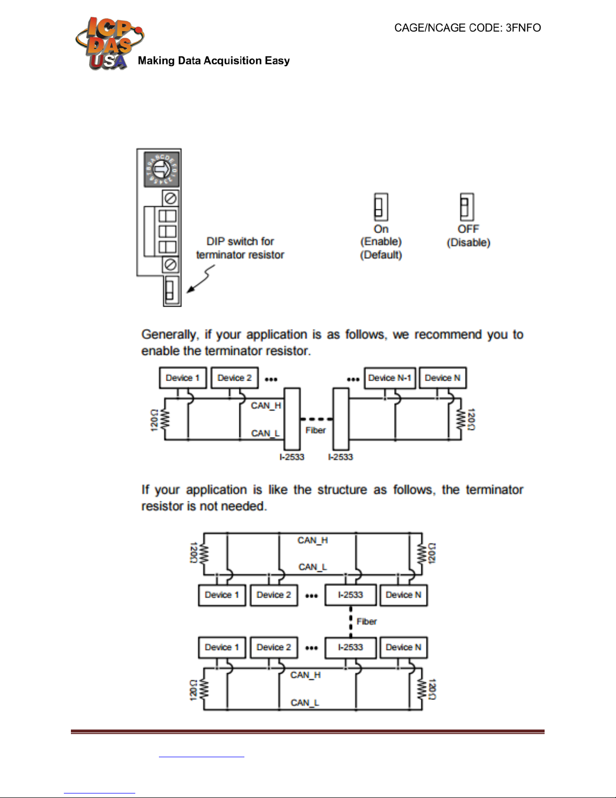
3. Check the application structure, and determine if the terminator resistor is
needed or not. You can find it at the position as follows.
I-2533 CAN to Fiber Multi-Mode Bridge - QuickStart (Nov/2016)
ICP DAS USA, Inc. | www.icpdas-usa.com | 1-310-517-9888 | 24309 Narbonne Ave. Suite 200. Lomita, CA 90717
3
Page 4

4. Connect the fiber port of these I-2533, CAN port, power line and frame
ground. The pin assignment and wire connection are as follows. When
finished, run your application with the I-2533.
I-2533 CAN to Fiber Multi-Mode Bridge - QuickStart (Nov/2016)
ICP DAS USA, Inc. | www.icpdas-usa.com | 1-310-517-9888 | 24309 Narbonne Ave. Suite 200. Lomita, CA 90717
4
Page 5

3. Utility Tool
When users want to use user-defined baud rate or set the message fil ter , I-2533 utility
tool may be needed. It can be free downloaded from the following web site or get it in
the product CD (path: CAN/C onverter/I-2533 /Softw ar e) :
http://www.icpdas-usa.com/i_2533.html
After getting the utility tool, please follow the following steps to set the baud rate and
message filter.
Step0: Power off the I-2533. Set the rotary switch to “F”, and connect the PC available
COM port with the COM port of the I-2533. Users can find the communication cable in
the product box. When connecting to the COM port of I-2533, the TxD pin of the cable
is connected to the TXD pin of the COM port, RXD pin of the cable is connected to the
RXD pin of the COM port, and GND pin of the cable is connected to the GND pin of
the COM port. Then, power on the I-2533.
Step1: Execute the I2533_Utility.exe, the dialog of the I-2533 Utility will be poped up.
Select the PC COM port which is connected with the COM port of the I-2533. Then,
click “Connect” button.
I-2533 CAN to Fiber Multi-Mode Bridge - QuickStart (Nov/2016)
ICP DAS USA, Inc. | www.icpdas-usa.com | 1-310-517-9888 | 24309 Narbonne Ave. Suite 200. Lomita, CA 90717
5
Page 6

Step2: Users can set the baud rate on the “User-defined Baud Rate” field. Here, fill
“250000” for 250 kbps. Then, set the filter by using the “from” field, “to” field, and “Add”
button. For example, If users want to pass the CAN message with ID 0x4 and 0x5 in the
CAN 2.0A specification. Fill the value “4” in the “from” field of CAN 2.0A, and the value
“5” in the “to” field of CAN 2.0A.
Step3: Click “Add” button to add this configuration. The configuration is shown on the
“Pass List” field. If the “Pass List” is not empty, only the messages matched with the
“Pass List” will be passed. If the “Pass List” filed is empty, it means all-pass. If users
want to pass the message with ID 0x0 in the CAN 2.0A specification, fill the value “0” in
both of “from” and “to” field and click “Add” button.
I-2533 CAN to Fiber Multi-Mode Bridge - QuickStart (Nov/2016)
ICP DAS USA, Inc. | www.icpdas-usa.com | 1-310-517-9888 | 24309 Narbonne Ave. Suite 200. Lomita, CA 90717
6
Page 7

Step4:.The method of configuring the message filter of the CAN 2.0B messages is
similar with the configuration steps of the message filter of the CAN 2.0A messages.
After finishing all of the configurations, click “Save all configuration” to store the
configuration in the I-2533.
Step5: When the procedure is successful, the following message will be shown.
Step6. After finishing the configuration, set the rotary switch value to “0” ~ “A” and
reboot the I-2533. The CAN message filter will be applied automatically in the value “0”
~ “A” of the rotary switch. The CAN baud rate set by utility is only appled when the
rotary switch is set t o “A ”.
I-2533 CAN to Fiber Multi-Mode Bridge - QuickStart (Nov/2016)
ICP DAS USA, Inc. | www.icpdas-usa.com | 1-310-517-9888 | 24309 Narbonne Ave. Suite 200. Lomita, CA 90717
7
Page 8

4. Dimension
I-2533 CAN to Fiber Multi-Mode Bridge - QuickStart (Nov/2016)
ICP DAS USA, Inc. | www.icpdas-usa.com | 1-310-517-9888 | 24309 Narbonne Ave. Suite 200. Lomita, CA 90717
8
 Loading...