

Page 1

User Manual
Version 1.31 July 2010
HRT-710
HRT-310
Written by Peter Ho
Edited by Julia Wang
Page 2

Table of Contents
1. Introduction .........................................................................................................................6
1.1 Features..........................................................................................................................7
1.2 Modbus Function Code Support .....................................................................................8
1.3 Specifications..................................................................................................................8
2. Hardware............................................................................................................................10
2.1 Block Diagram............................................................................................................... 10
2.2 Pin Assignment .............................................................................................................10
2.3 Wiring............................................................................................................................13
2.3.1 RS-232 Wiring ........................................................................................................13
2.3.2 RS-485 Wiring ........................................................................................................13
2.3.3 RS-422 Wiring ........................................................................................................14
2.3.4 HART Wiring........................................................................................................... 14
2.4 LED indicator ................................................................................................................18
2.5 DIP Switch ....................................................................................................................19
2.5.1 The default values in the “Default” mode................................................................20
2.6 Jumper .......................................................................................................................... 21
2.7 Module Loop Power Wiring (HRT-310) ......................................................................... 22
3. HART Introduction ............................................................................................................23
3.1 Analog and Digital signal............................................................................................... 23
3.2 Network topology ..........................................................................................................24
3.3 HART Frame.................................................................................................................26
3.3.1 Preamble ................................................................................................................26
3.3.2 Delimiter .................................................................................................................26
3.3.3 Address ..................................................................................................................26
3.3.4 Command ............................................................................................................... 26
3.3.5 Byte Count..............................................................................................................27
3.3.6 Response Codes .................................................................................................... 27
3.3.7 Data........................................................................................................................28
3.3.8 Check Byte .............................................................................................................28
4. Modbus Communication ..................................................................................................29
HR
T-710 / HRT-310 User Manual Version 1.31 Page:
2
Copyright © 2017 ICP DAS Co., Ltd. All Rights Reserved E-mail: service@icp das.com
Page 3

4.1 Module Execution Process............................................................................................ 29
4.2 Modbus / HART Mapping Table ....................................................................................30
4.3 Diagnostic Messages.................................................................................................... 37
4.4 Through Mode............................................................................................................... 38
4.5 Data Exchange Example............................................................................................... 39
5. HG_T ool Application.........................................................................................................42
5.1 Install .NET Compact Framework .................................................................................42
5.2 Install HG_Tool.............................................................................................................. 44
5.3 HG_Tool Utility ..............................................................................................................47
5.3.1 Traffic Light.............................................................................................................47
5.3.2 Connection Status ..................................................................................................47
5.3.3 Connection Control.................................................................................................48
5.3.4 Tools ....................................................................................................................... 48
5.3.4.1 Communication Settings......................................................................................... 48
5.3.4.2 Device Information.................................................................................................. 49
5.3.4.3 Device Configuration ..............................................................................................56
5.3.4.4 Default Output Data................................................................................................62
5.3.4.5 Address Map ..........................................................................................................63
5.3.4.6 Device Diagnostic...................................................................................................64
5.3.4.7 Through Mode ........................................................................................................65
5.3.4.8 Format Translation..................................................................................................66
5.3.4.9 About ...................................................................................................................... 67
5.4 Establish connection with module ................................................................................. 68
6. Troubleshooting................................................................................................................71
7. Dimensions........................................................................................................................72
8. FAQ.....................................................................................................................................
76
Q01 : How to add HART devices to HRT-710 ? ................................................................. 76
Q02 : How to make sure that HRT-710 gets the HART device data correctly ?.................81
Q03 : How to map HART device CMD(3) data directly to SCADA or HMI ? ......................84
Q04 : How to update the firmware of HRT-710 ? ...............................................................96
Q05 : How to read HART device CMD1 data with standard format by Modbus ? .............. 99
Q06 : How to read HART device CMD 3 data with standard format by Modbus ? ...........103
Q07 : How to know the connection status between HRT-710 and HART devices ? ........106
Q09 : How to integrate multiple HRT-710 in the same RS-485 ?..................................... 112
HR
T-710 / HRT-310 User Manual Version 1.31 Page:
3
Copyright © 2017 ICP DAS Co., Ltd. All Rights Reserved E-mail: service@icp das.com
Page 4

HRT-710 / HRT-310 User Manual Version 1.31 Page:
4
Copyright © 2017 ICP DAS Co., Ltd. All Rights Reserved E-mail: service@icp das.com
Q10 : How to integrate HART comm. device with RS-232 hardware interface ? ............. 114
Q11 : How to add the HART Device-Specific command to HRT-710 ? ............................ 115
Q12 : How to set HART device address by HRT-710 utility ? .......................................... 118
Q13 : All kinds of HART network wiring ? ........................................................................121
Q14 : Apply the same settings to the other H
RT-710 rapidly ? ........................................124
Q15 : How to send HART command for writi
ng ? (Ex: CMD19)....................................... 126
Q16 : Integrate GT-540 to get HART device data via 3G ?..............................................130
Appendix A. HART Command...............................................................................................136
Appendix B. Command Format ............................................................................................142
Appendix C: Version History..............................................................................................143
Page 5

Important Information
Warranty
All products manufactured by ICP DAS are under warranty regarding
defective materials for a period of one year, beginning from the date of
delivery to the original purchaser.
Warning
ICP DAS assumes no liability for any damage resulting from the use of this
product.ICP DAS reserves the right to change this manual at any time
without notice. The information furnished by ICP DAS is believed to be
accurate and reliable. However, no responsibility is assumed by ICP DAS
for its use, not for any infringements of patents or other rights of third parties
resulting from its use.
Copyright
Copyright @ 2017 by ICP DAS Co., Ltd. All rights are reserved.
Trademark
Names are used for identification purpose only and may be registered
trademarks of their respective companies.
Contact us
If you encounter any problems while operating this device, feel free to contact us
via mail at: service@icpdas.com . We guarantee to respond within 2 working days.
HR
T-710 / HRT-310 User Manual Version 1.31 Page:
5
Copyright © 2017 ICP DAS Co., Ltd. All Rights Reserved E-mail: service@icp das.com
Page 6

1. Introduction
Modbus and HART are two kinds of famous protocols and used wildly in the fields of factory and
process automation. The HRT-710 / HRT-310 module is a Modbus to HART gateway. By using
this module, users can integrate their HART devices into Modbus network easily. The below
figure is the application of HRT-710 / HRT-310.
(Note : The below description of HRT-710 / HRT-310 will be HRT-7(3)10)
Figure 1: The application of HRT-710 / HRT-310
The below table are the difference between HRT-710 and HRT-310.
HRT-710 HRT-310
Din Rail Installation Horizontal Upright
HART Signal Standard
Enhanced send/receive signal
(For long distance comm.)
Loop Power No
Support
(module provides +30V output)
Built-In Resistor 250 Ohm (1/4W) 250 Ohm (1W)
[ Note ]
1. The software settings for HRT-710 and HRT-310 are all the same and HG_Tool can be used
for them.
The main features and specifications of HRT-7(3)10 are described as below.
HR
T-710 / HRT-310 User Manual Version 1.31 Page:
6
Copyright © 2017 ICP DAS Co., Ltd. All Rights Reserved E-mail: service@icp das.com
Page 7

1.1 Features
Hardware
Support HART Short/Long frame.
Support HART Burst mode.
Allow two HART Masters.
Support Modbus RTU and ASCII format.
Support Modbus Slave / HART Master Mode.
Support firmware update via Com Port. (FW_v1.2 and HW_v1.2)
Support on-line replacement of HART devices. (FW_v1.5)
Support acquire long frame address automatically (FW_v1.5)
Isolated COM 1: RS-232/422/485.
Provide LED indicators.
Built-in Watchdog.
DIN-Rail or Wall Mounting.
HR
T-710 / HRT-310 User Manual Version 1.31 Page:
7
Copyright © 2017 ICP DAS Co., Ltd. All Rights Reserved E-mail: service@icp das.com
Page 8

1.2 Modbus Function Code Support
HRT-7(3)10 supports the following Modbus Function Code commands.
[ Table 1: Modbus Function Codes ]
FC Description
01 Read multiple coils status
02 Read multiple discrete inputs
03 Read multiple Holding registers
04 Read multiple input registers
05 Write single coil
06 Write single register
15 Force multiple coils
16 Write multiple registers
1.3 Specifications
[ UART Spec. ]
COM: RS-232(3 wire) / RS-422 / RS-485
HRT-710 Connector: 9-pin screwed terminal block
HRT-310 Connector: 4-pin screwed terminal block
Baud Rate: 1200 ~ 115200 bps
Data Format:
[1] data bits : 7/8
[2] parity : None/Odd/Even
[3] stop bit : 1/2
[ HART Spec. ]
Channel number: 1
Connector: 2-pin screwed terminal block
Operates as a HART Master station and supports all HART commands
Frame: Short or Long
Network: Point to Point or Multi-drop
HR
T-710 / HRT-310 User Manual Version 1.31 Page:
8
Copyright © 2017 ICP DAS Co., Ltd. All Rights Reserved E-mail: service@icp das.com
Page 9

Max. 15 HART modules
Max. 100 user commands and 32 default commands
[ Power Requirement ]
Unregulated +10 ~ +30 VDC
Power reverse protection, Over-Voltage brown-out protection
HRT-710 Power consumption: 1.0 W
HRT-310 Power consumption: 3.5 W (Max.)
[ Module Spec. ]
HRT-710 Dimensions: 72 mm x 121 mm x 35 mm (W x L x H)
HRT-310 Dimensions: 25 mm x 116 mm x 120 mm (W x L x H)
Operating temperature: -25 ~ 75 ºC
Storage temperature: -30 ~ 80 ºC
Humidity: 5 ~ 95% RH, non-condensing
LED Status Indicators (Table 2)
[ Table 2: LED status indicator ]
PWR LED Show module power status
ERR LED Show HART communication error status
RUN LED Show module operation status
HR
T-710 / HRT-310 User Manual Version 1.31 Page:
9
Copyright © 2017 ICP DAS Co., Ltd. All Rights Reserved E-mail: service@icp das.com
Page 10
2. Hardware
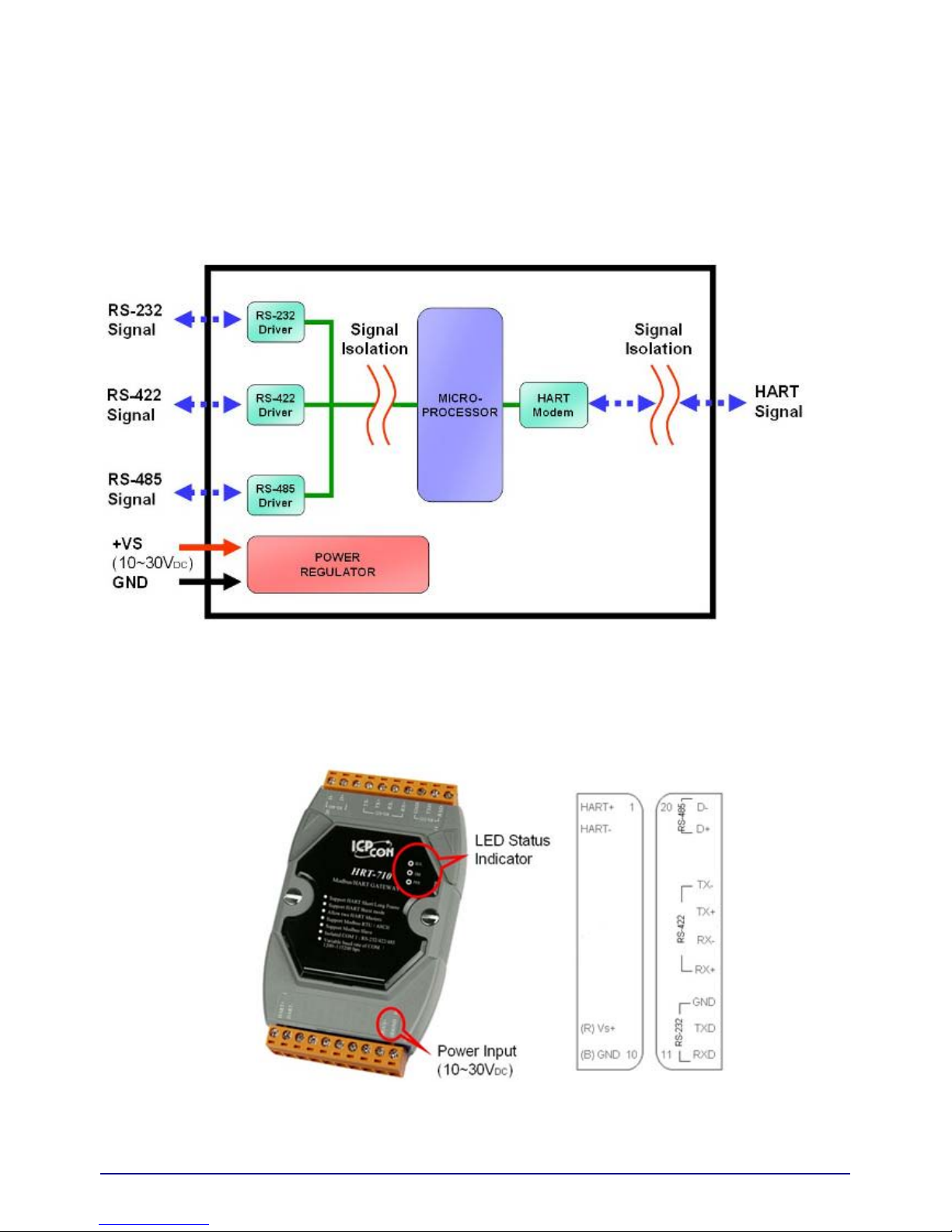
2.1 Block Diagram
Figure 2: Block diagram
2.2 Pin Assignment
Figure 3.1: Pin assignment of HRT-710
HR
T-710 / HRT-310 User Manual Version 1.31 Page:
10
Copyright © 2017 ICP DAS Co., Ltd. All Rights Reserved E-mail: service@icp das.com
Page 11

Top View Bottom View
Figure 3.2: Pin assignment of HRT-310
HR
T-710 / HRT-310 User Manual Version 1.31 Page:
11
Copyright © 2017 ICP DAS Co., Ltd. All Rights Reserved E-mail: service@icp das.com
Page 12

[ Table 3: Screw terminal block ]
Name
HRT-710
Pin
HRT-310
Pin
Description
LP+ N/A 12 V+ of Loop Power (+30Vdc)
HART+ 1 11 Positive of HART
HART- 2 10 Negative of HART
+VS 9 23 V+ of Power Supply (+10 ~ +30 Vdc)
GND 10 24 GND of Power Supply
RXD 11 18 Receive Data of RS-232
TXD 12 17 Transmit Data of RS-232
GND 13 19 GND of RS-232
RX+ 14 15 Receive Data+ of RS-422
RX- 15 16 Receive Data- of RS-422
TX+ 16 13 Transmit Data+ of RS-422
TX- 17 14 Transmit Data- of RS-422
D+ 19 13 Data+ of RS-485
D- 20 14 Data- of RS-485
HR
T-710 / HRT-310 User Manual Version 1.31 Page:
12
Copyright © 2017 ICP DAS Co., Ltd. All Rights Reserved E-mail: service@icp das.com
Page 13
2.3 Wiring
It is recommended to use only one serial port interface (RS232, RS422 or RS485) of the
HRT(3)-710 module at a time. The following section describes the necessary steps to connect
one of the three COM port types to a Modbus network.
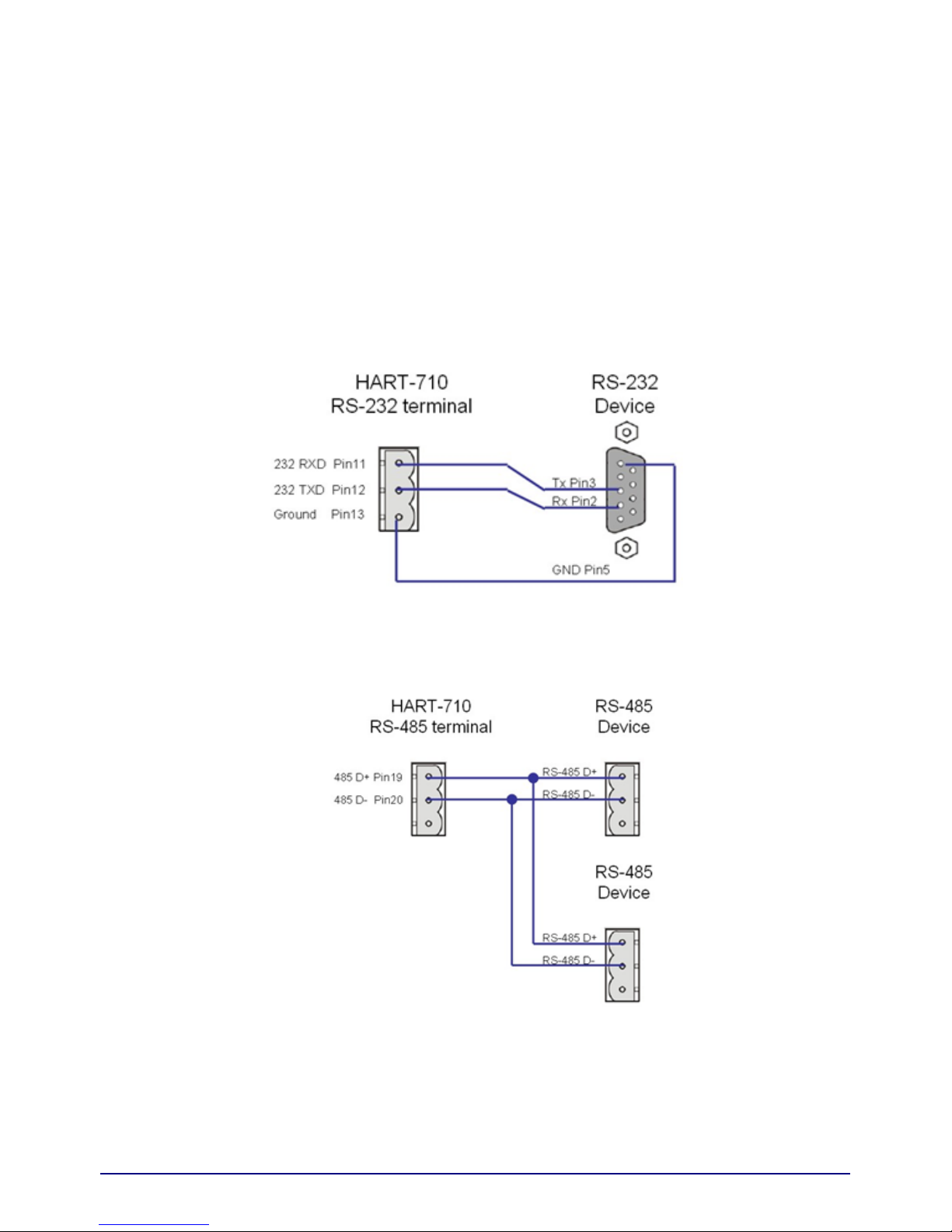
2.3.1 RS-232 Wiring
The RS-232 port of the HRT-7(3)10 has only three pins. The wiring of the RS-232 device
with the RS-232 port of the HRT-7(3)10 is shown as Figure 4.
Figure 4: RS-232 wiring diagram
2.3.2 RS-485 Wiring
The RS-485 wiring is shown as Figure 5.
Figure 5: RS-485 wiring diagram
HR
T-710 / HRT-310 User Manual Version 1.31 Page:
13
Copyright © 2017 ICP DAS Co., Ltd. All Rights Reserved E-mail: service@icp das.com
Page 14
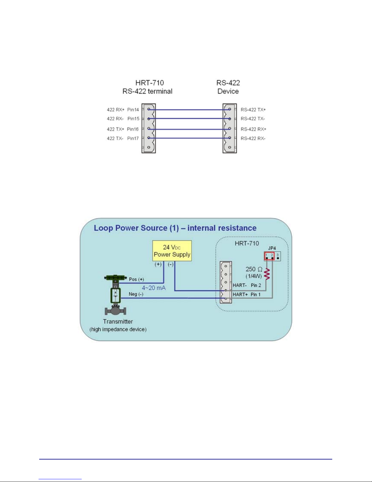
2.3.3 RS-422 Wiring
The RS-422 wiring is shown as Figure 6.
Figure 6: RS-422 wiring diagram
2.3.4 HART Wiring
The HART bus wiring is divided into the below two types:
(1) “Point-to-Point” mode.
(2) “Multi-drop” mode.
Fig 2.3.4-1 : “P2P” mode (Two-wired HART device, Module Internal Resistor)
HR
T-710 / HRT-310 User Manual Version 1.31 Page:
14
Copyright © 2017 ICP DAS Co., Ltd. All Rights Reserved E-mail: service@icp das.com
Page 15

Fig 2.3.4-2 : “P2P” mode (Two-wired HART device, External Resistor)
Fig 2.3.4-3 : “P2P” mode (Four-wired HART device)
HR
T-710 / HRT-310 User Manual Version 1.31 Page:
15
Copyright © 2017 ICP DAS Co., Ltd. All Rights Reserved E-mail: service@icp das.com
Page 16

Fig 2.3.4-4 : “Multi-drop” mode (Two-wired HART device)
Fig 2.3.4-5 : “Multi-drop” mode (Four-wired HART device)
HR
T-710 / HRT-310 User Manual Version 1.31 Page:
16
Copyright © 2017 ICP DAS Co., Ltd. All Rights Reserved E-mail: service@icp das.com
Page 17

Fig 2.3.4-6 : “Multi-drop” mode (Two-wired and Four-w ired HART device)
HR
T-710 / HRT-310 User Manual Version 1.31 Page:
17
Copyright © 2017 ICP DAS Co., Ltd. All Rights Reserved E-mail: service@icp das.com
Page 18
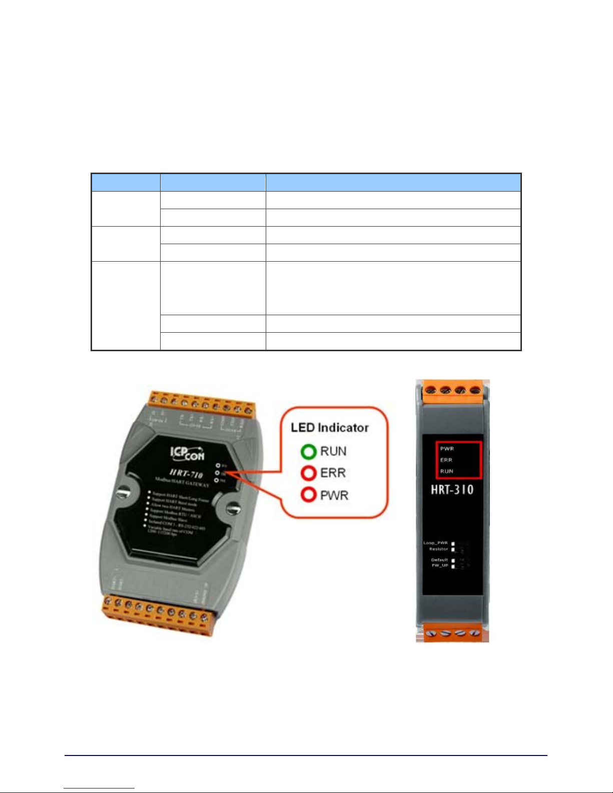
2.4 LED indicator
The HRT-7(3)10 provides three LEDs to indicate the module and the HART communication
status.
[ Table 4: LED status description ]
LED Name Status Description
ON Power Supply OK.
PWR
OFF Power Supply Failed.
Flash HART Comm. Error.
ERR
OFF HART Comm. OK
Flash
[ Flash per second ]
Module in initial mode.
[ Flash per half second ]
Module received the burst frame from HART device.
ON Module in normal operation.
RUN
OFF Firmware has not been loaded yet.
Figure 11: HRT-710 / HRT-310 LED indicator
HR
T-710 / HRT-310 User Manual Version 1.31 Page:
18
Copyright © 2017 ICP DAS Co., Ltd. All Rights Reserved E-mail: service@icp das.com
Page 19

2.5 DIP Switch
1. HRT-710 :
There is a DIP Switch on the backplane of the HRT-710, as shown in Figure 12.
(1) “Normal” :
[1] The user’s settings will be adapted in HRT-710.
[2] In normal operation, set the DIP Switch to the “Normal” position.
(2) “Default” :
[1] The system default settings will be adapted in HRT-710.
[2] When users forgot the settings of HRT-710 and can’t connect to HRT-710 successfully,
users can set the DIP Switch to the “Default” position and reset HRT-710. Then the
default settings (refer to section 2.5.1) of HRT-710 will be adapted.
Figure 12-1: DIP Switch of the HRT-710
2. HRT-310 :
There are 4 dip-switches on the HRT-310 and these functions are as below.
Item OFF ON
Loop PWR
Adapt the external power for HART
loop
(Default)
Adapt the Loop Power for HART loop
(Wiring refer to section 2.7)
Resistor Disable HART loop resistor
Enable HART loop resistor (Default)
(250 Ohm, 1W)
Default Adapt the user’s settings (Default)
Adapt the default settings.
(Refer to section 2.5.1)
FW Update Firmware Operation (Default)
Firmware Update
(Refer to the Q04 of FAQ)
HR
T-710 / HRT-310 User Manual Version 1.31 Page:
19
Copyright © 2017 ICP DAS Co., Ltd. All Rights Reserved E-mail: service@icp das.com
Page 20

Figure 12-2: DIP Switches of the HRT-310
2.5.1 The default values in the “Default” mode.
[ System Default Value ]
Item Value
HART Cmd interval 1000 ms
HART Cmd timeout value 1000 ms
Auto. Polling Enabled
Retry count 3
[ Modbus Default Value ]
Item Value
Baud rate 115200 bps
Date bits 8 bits
Stop bits 1 bit
Parity None
Net ID (Modbus ID) 1
Protocol Modbus RTU Slave
Swap mode None
HR
T-710 / HRT-310 User Manual Version 1.31 Page:
20
Copyright © 2017 ICP DAS Co., Ltd. All Rights Reserved E-mail: service@icp das.com
Page 21

2.6 Jumper
1. HRT-710 :
There is a Jumper (JP4) in the HRT-710 module shown as Figure 13. The jumper can provide
HART bus with 250Ω (1/4 W) resistor. When the pin 1&2 of JP4 is closed, the resistor will
connect to HART bus. When the pin 2&3 of JP4 is closed or JP4 without jumper connected, it will
disconnect the resistor from HART bus. By default, the pin1&2 of JP4 is closed. Please refer to
section 2.3.4 - HART connection for detail.
Figure 13: Jumper of the HRT-710
HR
T-710 / HRT-310 User Manual Version 1.31 Page:
21
Copyright © 2017 ICP DAS Co., Ltd. All Rights Reserved E-mail: service@icp das.com
Page 22

2.7 Module Loop Power Wiring (HRT-310)
HRT-310 supports “Loop Power” function and it means HRT-310 can provide +30V via “LP+” pin.
The “Loop Power” wiring is as below.
(1) Connect the “LP+” (+30V) of HRT-310 to the “HART+” pin of HART device.
(2) Connect the “H+” of HRT-310 to the “HART-” pin of HART device.
(3) Turn the “dip-switch of Loop Power” in HRT-310 to “ON” position.
(It will connect the “H-” of HRT-310 to the internal “LP-” of HRT-310.)
(Note: HRT-710 doesn’t support the Loop Power function.)
HR
T-710 / HRT-310 User Manual Version 1.31 Page:
22
Copyright © 2017 ICP DAS Co., Ltd. All Rights Reserved E-mail: service@icp das.com
Page 23

3. HART Introduction
3.1 Analog and Digital signal
The HART communication protocol is based on the Bell 202 telephone communication standard
and operates using the frequency shift keying (FSK, Figure 14) principle. The digital signal is
made up of two frequencies - 1,200 Hz and 2,200 Hz representing bits 1 and 0, respectively. Sine
waves of these two frequencies are superimposed on the direct current (dc) analog signal cables
to provide simultaneous analog and digital communications (Figure 15).
Figure 14: FSK signal
Figure 15: Analog and digital signals
HR
T-710 / HRT-310 User Manual Version 1.31 Page:
23
Copyright © 2017 ICP DAS Co., Ltd. All Rights Reserved E-mail: service@icp das.com
Page 24

3.2 Network topology
HART bus can operate in one of these two network configurations—point to point and multi-drop.
1. Point to Point Mode :
In point to point mode, the analog signal is used to communicate one process variable and the
digital signal gives access to secondary variables and other data that can be used for operations,
commissioning, maintenance and diagnostic purposes. Only one HART slave device can exist in
HART bus and the polling address must be zero.
Figure 16: “Point to Point” topology
2. Multi-drop Mode :
In multi-drop mode, all process values are transmitted digitally. The polling address of all field
devices must be bigger than 0 and between 1 ~ 15. The current through each device is fixed to a
minimum value (typically 4 mA). The maximum HART device number in HART bus is up to 15.
[ Note ]
1. The built-in resistor in HRT-710 is 250 Ohm with 1/4W. Therefore, HRT-710 supports to
connect the maximum 7 HART devices simultaneously. If the HART devices in multi-drop
mode are more than 7, then users need to disconnect the built-in resistor in HRT-710
(prevent to burn down) and use the external 250 Ohm resistor with 1W.
2. The built-in resistor in HRT-310 is 250 Ohm with 1W and it allows up to 15 HART devices
to be connected.
HR
T-710 / HRT-310 User Manual Version 1.31 Page:
24
Copyright © 2017 ICP DAS Co., Ltd. All Rights Reserved E-mail: service@icp das.com
Page 25

Figure 17: “Multi-drop” topology
HR
T-710 / HRT-310 User Manual Version 1.31 Page:
25
Copyright © 2017 ICP DAS Co., Ltd. All Rights Reserved E-mail: service@icp das.com
Page 26
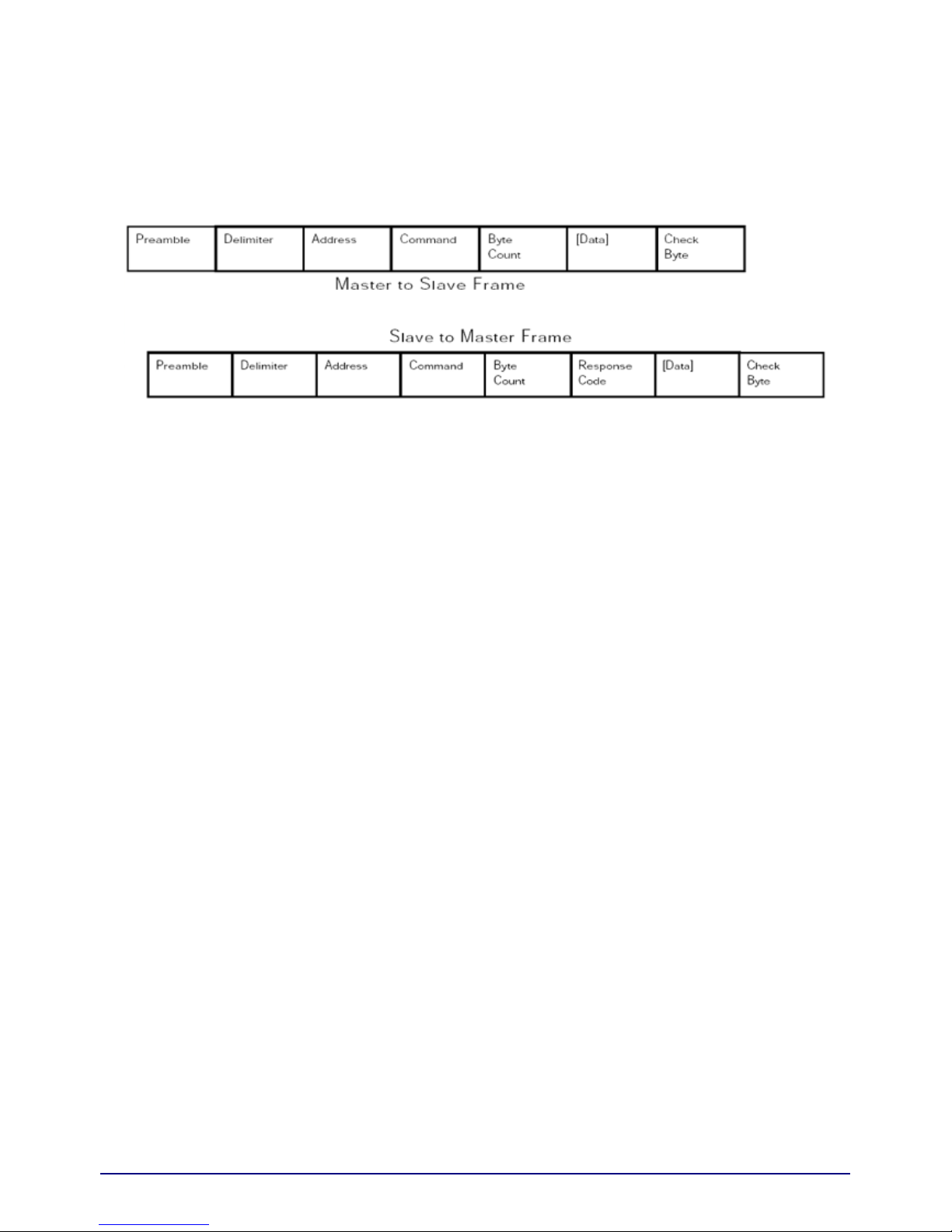
3.3 HART Frame
The HART frame format is shown as below:
Figure 18: HART frame format
3.3.1 Preamble
All frames transmitted by HART master or slave devices are preceded by a specified
number of "0xFF" characters and they are called the preamble. The number of preamble
can’t be less than 5 and more than 20.
3.3.2 Delimiter
This data can indicate the frame is long or short frame and the frame is master frame, slave
frame or burst frame.
3.3.3 Address
If the HART frame is short frame, the address field is only one byte. If it is long frame, the
address field is 5 bytes and include manufacturer ID, device type and device ID.
3.3.4 Command
The HART command set includes three classes shown as below.
(1) Universal Command
(2) Common-Practice Command
(3) Device-Specific Command
Command Number Command Class
0 Universal
‧ ‧
‧ ‧
‧ ‧
30 Universal
31 Reserved
-----------------------------------------------------------------------
32 Common Practice
HR
T-710 / HRT-310 User Manual Version 1.31 Page:
26
Copyright © 2017 ICP DAS Co., Ltd. All Rights Reserved E-mail: service@icp das.com
Page 27

‧ ‧
‧ ‧
‧ ‧
127 Reserved
-------------------------------------------------------
128 Transmitters-Specific
‧ ‧
‧ ‧
‧ ‧
253 Transmitters-Specific
------------------------------------------------------ 254 Reserved
255 Reserved
About the often used HART command, please refer to “Appendix A: HART command”.
3.3.5 Byte Count
It is the number of bytes between it and the check byte the end of the HART frame.
3.3.6 Response Codes
It includes two bytes of status. These bytes convey three types of information:
Communication errors, Command response problems and Field device status. They are
shown as below.
[ First Byte ]
bit 7: 1 (communication error)
bit 6: Parity error
bit 5: Overrun error
bit 4: Framing error
bit 3: Checksum error
bit 2: 0(reserved)
bit 1: Rx buffer overflow
bit 0: Overflow (undefined)
[ bit 7=0 (Comm. OK) ; Bit 0~6: as an integer, not bit-mapped ]
0: No command-specific error
1: (undefined)
2: Invalid selection
3: Passed parameter too large
4: Passed parameter too small
5: Too few data bytes received
6: Device-specific command error (rarely used)
HR
T-710 / HRT-310 User Manual Version 1.31 Page:
27
Copyright © 2017 ICP DAS Co., Ltd. All Rights Reserved E-mail: service@icp das.com
Page 28

7: In write-protect mode
8-15: Multiple meanings
16: Access restricted
28: Multiple meanings
32: Device is busy
64: Command not implemented
[ Second Byte - Field device status ]
bit 7: Field device malfunction
bit 6: Configuration changed
bit 5: Cold start
bit 4: More status available
bit 3: Analog output current fixed
bit 2: Analog output saturated
bit 1: Non-primary variable out of limits
bit 0: Primary variable out of limits.
[ Note ]
When HART communication error is reported in the first byte, the second byte will be 0.
3.3.7 Data
The contents of the data are decided by HART command number.
3.3.8 Check Byte
Every HART frame has a check byte at the last data byte. HART device can detect error
frame by this byte.
.
HR
T-710 / HRT-310 User Manual Version 1.31 Page:
28
Copyright © 2017 ICP DAS Co., Ltd. All Rights Reserved E-mail: service@icp das.com
Page 29
4. Modbus Communication
4.1 Module Execution Process
When HRT-7(3)10 module power on, it will enter the “Initial” mode first and then enter the
“Operation” mode.
(1) When HRT-7(3)10 runs under “Initial” mode, it will execute all initial commands and the
“RUN” LED will flash.
(2) When HRT-7(3)10 runs under “Operation” mode, it will execute all polling commands
automatically and the “RUN” LED will be always on.
[ Note ]
The “Auto Polling” function must be set to “Enable” and all polling command will be executed
automatically.
HR
T-710 / HRT-310 User Manual Version 1.31 Page:
29
Copyright © 2017 ICP DAS Co., Ltd. All Rights Reserved E-mail: service@icp das.com
Page 30

4.2 Modbus / HART Mapping Table
Users can access the HART device by using these Modbus address defined by HRT-7(3)10
module. These Modbus address can be divided into two parts as below.
(1) Input Data Area (FC04)
(2) Output Data Area (FC06, 16)
[ Note ]
The meaning of every Modbus address in the below table is according to the setting of SWAP
Mode to be None. If the setting of SWAP Mode is Byte or WORD or W&B, then the meaning of
every Modbus address in the below table will be moved one byte or word address.
[ Table 5: Modbus / HART Mapping Table ]
INPUT DATA AREA
MB_Addr
(HEX)
MB_Addr
(Decimal)
Description
[ User CMD Data ]
0~1F3 0~499 “User CMD“ data
[ Module State Data ]
1F4 500L Module state machine
1F4 500H Module request command count
1F5 501L Module receive command count
1F5 501H Module receive error command count
1F6 502L Module error status
1F6 502H Module error command index
1F7~1F9 503~505 Reserved
[ Default CMD(0) Data ]
1FA~200 506~512 “Default CMD(0)” input data of “Module 0”
201~207 513~519 “Default CMD(0)” input data of “Module 1”
208~20E 520~526 “Default CMD(0)” input data of “Module 2”
20F~215 527~533 “Default CMD(0)” input data of “Module 3”
216~21C 534~540 “Default CMD(0)” input data of “Module 4”
21D~223 541~547 “Default CMD(0)” input data of “Module 5”
HR
T-710 / HRT-310 User Manual Version 1.31 Page:
30
Copyright © 2017 ICP DAS Co., Ltd. All Rights Reserved E-mail: service@icp das.com
Page 31

HR
T-710 / HRT-310 User Manual Version 1.31 Page:
31
Copyright © 2017 ICP DAS Co., Ltd. All Rights Reserved E-mail: service@icp das.com
INPUT DATA AREA
MB_Addr
(HEX)
MB_Addr
(Decimal)
Description
224~22A 548~554 “Default CMD(0)” input data of “Module 6”
22B~231 555~561 “Default CMD(0)” input data of “Module 7”
232~238 562~568 “Default CMD(0)” input data of “Module 8”
239~23F 569~575 “Default CMD(0)” input data of “Module 9”
240~246 576~582 “Default CMD(0)” input data of “Module 10”
247~24D 583~589 “Default CMD(0)” input data of “Module 11”
24E~254 590~596 “Default CMD(0)” input data of “Module 12”
255~25B 597~603 “Default CMD(0)” input data of “Module 13”
25C~262 604~610 “Default CMD(0)” input data of “Module 14”
263~269 611~617 “Default CMD(0)” input data of “Module 15”
[ Default CMD(3)(N) Data ]
26A~276 618~630 “Default CMD(3)(N)” data of “Module 0”
277~283 631~643 “Default CMD(3)(N)” data of “Module 1”
284~290 644~656 “Default CMD(3)(N)” data of “Module 2”
291~29D 657~669 “Default CMD(3)(N)” data of “Module 3”
29E~2AA 670~682 “Default CMD(3)(N)” data of “Module 4”
2AB~2B7 683~695 “Default CMD(3)(N)” data of “Module 5”
2B8~2C4 696~708 “Default CMD(3)(N)” data of “Module 6”
2C5~2D1 709~721 “Default CMD(3)(N)” data of “Module 7”
2D2~2DE 722~734 “Default CMD(3)(N)” data of “Module 8”
2DF~2EB 735~747 “Default CMD(3)(N)” data of “Module 9”
2EC~2F8 748~760 “Default CMD(3)(N)” data of “Module 10”
2F9~305 761~773 “Default CMD(3)(N)” data of “Module 11”
306~312 774~786 “Default CMD(3)(N)” data of “Module 12”
313~31F 787~799 “Default CMD(3)(N)” data of “Module 13”
320~32C 800~812 “Default CMD(3)(N)” data of “Module 14”
32D~339 813~825 “Default CMD(3)(N)” data of “Module 15”
[ Module Error Record Data ]
33A~373 826~883 Module Error Record 1
Page 32

HR
T-710 / HRT-310 User Manual Version 1.31 Page:
32
Copyright © 2017 ICP DAS Co., Ltd. All Rights Reserved E-mail: service@icp das.com
INPUT DATA AREA
MB_Addr
(HEX)
MB_Addr
(Decimal)
Description
374~3AD 884~941 Module Error Record 2
3AE~3E7 942~999 Module Error Record 3
[ Default CMD(0&3) Status Data ]
3E8 1000 “Default CMD(0&3)” status of “Module 0”
3E9 1001 “Default CMD(0&3)” status of “Module 1”
3EA 1002 “Default CMD(0&3)” status of “Module 2”
3EB 1003 “Default CMD(0&3)” status of “Module 3”
3EC 1004 “Default CMD(0&3)” status of “Module 4”
3ED 1005 “Default CMD(0&3)” status of “Module 5”
3EE 1006 “Default CMD(0&3)” status of “Module 6”
3EF 1007 “Default CMD(0&3)” status of “Module 7”
3F0 1008 “Default CMD(0&3)” status of “Module 8”
3F1 1009 “Default CMD(0&3)” status of “Module 9”
3F2 1010 “Default CMD(0&3)” status of “Module 10”
3F3 1011 “Default CMD(0&3)” status of “Module 11”
3F4 1012 “Default CMD(0&3)” status of “Module 12”
3F5 1013 “Default CMD(0&3)” status of “Module 13”
3F6 1014 “Default CMD(0&3)” status of “Module 14”
3F7 1015 “Default CMD(0&3)” status of “Module 15”
3F8~419 1016~1049 Reserved
[ User CMD Error Status Data ]
41A~44B 1050~1099 “User CMD(0~99)” error status
[ Module Hardware Data ]
44C~44D 1100~1101 Module ID (“HART”)
44E~455 1102~1109 Module Name (16 Bytes)
456~459 1110~1113 Module Firmware Version (8 Bytes)
45A~47D 1114~1149 Reserved
[ Through Mode Data ]
Page 33

HR
T-710 / HRT-310 User Manual Version 1.31 Page:
33
Copyright © 2017 ICP DAS Co., Ltd. All Rights Reserved E-mail: service@icp das.com
INPUT DATA AREA
MB_Addr
(HEX)
MB_Addr
(Decimal)
Description
47E 1150L Send count in through mode
47E 1150H Receive count in through mode
47F 1151L Receive error count in through mode
47F 1151H Reserved
480 1152 Receive length in through mode
481~50E 1153~1294 Receive data in through mode
50F~513 1295~1299 Reserved
[ Default CMD(3)(S) Data (FW_v1.5) ]
514~51D 1300~1309 “Default CMD(3)(S)” data of “Module 0”
51E~527 1310~1319 “Default CMD(3)(S)” data of “Module 1”
528~531 1320~1329 “Default CMD(3)(S)” data of “Module 2”
532~53B 1330~1339 “Default CMD(3)(S)” data of “Module 3”
53C~545 1340~1349 “Default CMD(3)(S)” data of “Module 4”
546~54F 1350~1359 “Default CMD(3)(S)” data of “Module 5”
550~559 1360~1369 “Default CMD(3)(S)” data of “Module 6”
55A~563 1370~1379 “Default CMD(3)(S)” data of “Module 7”
564~56D 1380~1389 “Default CMD(3)(S)” data of “Module 8”
56E~577 1390~1399 “Default CMD(3)(S)” data of “Module 9”
578~581 1400~1409 “Default CMD(3)(S)” data of “Module 10”
582~58B 1410~1419 “Default CMD(3)(S)” data of “Module 11”
58C~595 1420~1429 “Default CMD(3)(S)” data of “Module 12”
596~59F 1430~1439 “Default CMD(3)(S)” data of “Module 13”
5A0~5A9 1440~1449 “Default CMD(3)(S)” data of “Module 14”
5AA~5B3 1450~1459 “Default CMD(3)(S)” data of “Module 15”
OUTPUT DATA
MB_Addr
(HEX)
MB_Addr
(Decimal)
Description
0~1F3 0~499 User command
Page 34

HR
T-710 / HRT-310 User Manual Version 1.31 Page:
34
Copyright © 2017 ICP DAS Co., Ltd. All Rights Reserved E-mail: service@icp das.com
OUTPUT DATA
MB_Addr
(HEX)
MB_Addr
(Decimal)
Description
1F4 500L Auto Polling function
1F4 500H Reserved
1F5 501L Reset module state function
1F5 501H Reserved
1F6 502L Output Trigger function
1F6 502H The index of trigger command
1F7~1F9 503~505 Reserved
1FA~76B 506~1899 Reserved (For Module Configuration)
76C 1900L Channel selection in through mode
76C 1900H Reserved
76D 1901 Send data length in through mode
76E~7FB 1902~2043 Send data in through mode
[ Note ]
(1) MB=Modbus, CMD=Command, MOD=Module, DEV=Device
(2) 500L: The low byte of MB_Addr 500.
500H: The high byte of MB_Addr 500
(3) Default CMD(num)(format):
[1] Num: means HART command number. When add a new HART device in module, these
two default commands – “Default CMD(0)” and “Default CMD(3)” will be produced
automatically.
[2] Format: means the format of HART command of HRT-7(3)10.
<1> Normal format (N): Use the standard HART command format.
<2> Simple format (S): Refer to “Appendix B: Command Format”.
(4) The description of the “Default CMD(0 & 3)” status:
It consists of two bytes. The first byte is the state of “Default CMD(0)” and the second byte is
the state of “Default CMD(3)”.
Ex: If the value is 0x0100 for the MB address 1000, then the 1000L is 0x00 and the 1000H is
0x01. It means the error status of “Default CMD(0)” is 0x00 and the error status of “Default
CMD(3)” is 0x01 in “Module 0”.
Page 35

(5) The description of the User CMD status:
The maximum number of “User CMD” is 100 (0~99). The MB address range for the error
status of these User CMD is 1050~1099. It means that one MB address represents two User
CMD states.
Ex: If the value is 0x0200 for the MB address 1050, then the 1050L is 0x00 and the 1050H is
0x02. It means the error status of “User CMD Index 0” is 0x00 and the error status of “User
CMD Index 1” is 0x02.
(6) Module state machine:
0 — IDLE.
1 — Waits to send HART command.
2 — It is sending HART command.
3 — Waits to receive HART data.
4 — It is reading HART data.
(7) Module error status:
0 — No error
1 — Means the command has never be executed
2 — Receive timeout, can’t receive any HART data
3 — Receive HART data is too short
4 — The delimiter of HART data has some error
5 — The address (the bit of master type) of HART data has some error
6 — The address (the bit of burst mode) of HART data has some error
7 — The command of HART data has some error
8 — The parity of HART data has error.
9 — The communication with HART slave device has some error and The error messages
are recorded in the responses codes.
(8) Module error command index:
The index value indicates the latest error user command number. If the value is 255, it means
no any error command happened.
(9) Module error record:
When the HART comm. error happened, HRT-7(3)10 will record the error information and it
provides 3 records. The format of the error record is as below:
Byte 0: The length of send data (1 Byte)
Byte 1~53: The record of send data (Max. 53 Bytes)
Byte 54: The length of receive data (1 Byte)
HR
T-710 / HRT-310 User Manual Version 1.31 Page:
35
Copyright © 2017 ICP DAS Co., Ltd. All Rights Reserved E-mail: service@icp das.com
Page 36

Byte 55~109: The record of receive data (Max. 55 Bytes)
Byte 110~113: The time stamp record (4 Bytes)
Byte 114~115: Reserved (2 Bytes)
(10) Module status reset function:
When set the value is bigger than zero, the module will clear “module request count”, “module
response count”, “module error count”, “module error status” and set “module error command
index” to 255.
(11) Auto Polling function:
When set the value to be 1, the module will execute all HART polling commands
automatically.
(12) Output Trigger function:
If change the value, the module will refer to the index value (0~99, 255 is for through mode) of
trigger command to execute the corresponding user command.
Ex: If the index of trigger command is 0 and the output trigger function value is 1, when
change the value of output trigger function from 1 to 2, the module will execute the user
command (index = 0).
(13) Default CMD(3)(S) Data: (FW_v1.5)
By using the address, users do not need to add the simple format of User CMD(3). Just do
the below setting, then HMI or SCADA can get the HART Cmd(3) data easily.
[1] Set "Default CMD(3) mode" to "Polling".
[2] Set "Swap mode" to "W&B".
[3] Run "Save to Device" function.
HR
T-710 / HRT-310 User Manual Version 1.31 Page:
36
Copyright © 2017 ICP DAS Co., Ltd. All Rights Reserved E-mail: service@icp das.com
Page 37

4.3 Diagnostic Messages
Please refer to section 4.3 - Modbus / HART Mapping Table. The related MB address is shown
as below.
Input Data Area Description
500~502 Module state data
826~883 Module error record data
1000~1015 “Default CMD(0&3)“ status data
1050~1099 “User CMD(0~99)“ error status
HR
T-710 / HRT-310 User Manual Version 1.31 Page:
37
Copyright © 2017 ICP DAS Co., Ltd. All Rights Reserved E-mail: service@icp das.com
Page 38

4.4 Through Mode
In this mode, users can send and receive the HART command directly. Please refer to the below
steps.
Step 1: Set the “Channel” to 0. (Through Mode just support channel 0)
[MB:1900L]
Step 2: Set the “Send length”. [MB:1901]
Step 3: Set the “HART command data”. [MB: 1902~2043]
Ex: 0xFF 0xFF 0xFF 0xFF 0xFF 0x02 0x80 0x00 0x00 0x82
Step 4: Set the “Auto Polling” to 0. [MB:501L]
(In this mode, “Auto Polling” function can’t be enabled.)
Step 5: Set the “The index of trigger command” to 255. [MB:502H]
Step 6: Get the receive count from “Receive count in through mode” [MB:1150H] and error count
from “Error count in through mode” [MB:1151L].
Step 7: Change the “Output Trigger function” value. [MB:502L]
Step 8: Get the value of “Receive count in through mode” and “Error count in through mode” until
one of them is different than the last value.
Step 9: If the “Receive count in through mode” is different than the last value, the user can get
the receive length from “Receive length in through mode” and the user can get receive
data from “Receive data in through mode” [MB:1153 ~ ] according to receive data length.
[MB:1152]
If the “Error count in through mode” is different than the last value, it means it can’t
receive any data.
HR
T-710 / HRT-310 User Manual Version 1.31 Page:
38
Copyright © 2017 ICP DAS Co., Ltd. All Rights Reserved E-mail: service@icp das.com
Page 39

4.5 Data Exchange Example
In this example, use ICP DAS MB/RTU master tool
(Download from: (http://ftp.icpdas.com.tw/pub/cd/8000cd/napdos/modbus/modbus_utility/) to
send the HART command 0 and receives the hardware information of HART slave via the
HRT-7(3)10 gateway.
Step 1: Please connect the PC、HRT-7(3)10 and HART Slave device.
Figure 21: Hardware connection
Step 2: Set the module to the default settings.
(1)HRT-710: Set the DIP switch in the backplane of HRT-710 to the “default” position.
(2)HRT-310: Set the “Default” dip switch to be “ON” position.
Please reboot the module and the default settings are as below.
Item Value
Baud rate 115200 bps
Date bits 8 bits
Stop bits 1 bit
Parity None
Net ID (Modbus ID) 1
Protocol Modbus RTU Slave
Step 3: Waiting for the “RUN” LED of HRT-7(3)10 to be always on.
Step 4: Run the MB/RTU tool (like Figure 22) on PC.
(1) Set the PC COM port number
(2) Set the baud rate to 115200
(3) Set the Line control to “N,8,1”
(4) Click “Open” button
HR
T-710 / HRT-310 User Manual Version 1.31 Page:
39
Copyright © 2017 ICP DAS Co., Ltd. All Rights Reserved E-mail: service@icp das.com
Page 40

Figure 22: MB/RTU Tool
Step 5: Send the Modbus command : 0x01 0x04 0x01 0xFA 0x00 0x07 0x90 0x05 [MB:
0x1FA~0x200, total word length is 7.]
Step 6: Receive and analyze the response data.
Here are the Modbus response data:
0x01 0x04 0x0E 0x10 0x00 0x3F 0xFE 0x08 0x04 0x01 0x05 0x1B 0x10 0x1B 0x00 0xE8
0x97 0x33 0xCC
The HART data is 7 Words (14 Bytes) as below:
Word 0: 0x10 (Byte 1) 0x00 (Byte 0)
Word 1: 0x3F (Byte 3) 0xFE (Byte 2)
Word 2: 0x08 (Byte 5) 0x04 (Byte 4)
Word 3: 0x01 (Byte 7) 0x05 (Byte 6)
Word 4: 0x1B (Byte 9) 0x10 (Byte 8)
Word 5: 0x1B (Byte 11) 0x00 (Byte 10)
Word 6: 0xE8 (Byte 13) 0x97 (Byte 12)
The HART command 0 format is 2 bytes response code and 12 bytes data.
[ Response code1 ]
Byte 0: 0x00 means “No Error”
[ Response code2 ]
Byte 1: 0x10 means “More Status Available”
[ Response data bytes of command 0 ]
Byte 2: 0xFE Constant value
Byte 3: 0x3F Manufacturer ID, 0x3F = “Eckardt”
Byte 4: 0x04 Manufacturer’s device ID
Byte 5: 0x08 Number of preambles needed in the request
Byte 6: 0x05 Command set revision number
Byte 7: 0x01 Transmitter specific revision code
HR
T-710 / HRT-310 User Manual Version 1.31 Page:
40
Copyright © 2017 ICP DAS Co., Ltd. All Rights Reserved E-mail: service@icp das.com
Page 41

Byte 8: 0x10 Software revision
Byte 9: 0x1B Hardware revision
Byte 10: 0x00 Flags
Byte 11~13: 0x1B 0x97 0xE8 Device ID number
Figure 23: Modbus RTU send and receive data
HR
T-710 / HRT-310 User Manual Version 1.31 Page:
41
Copyright © 2017 ICP DAS Co., Ltd. All Rights Reserved E-mail: service@icp das.com
Page 42

5. HG_Tool Application
5.1 Install .NET Compact Framework
It needs the runtime environment with .NET Framework 2.0 or above to execute the HG_Tool in
PC. If.NET Framework 2.0 or above exists in PC, the section 5.1 can be omitted.
◆
Microsoft .Net Framework Version 2.0:
http://www.microsoft.com/downloads/details.aspx?FamilyID=0856eacb-4362-4b0d-8edd-aab
15c5e04f5&DisplayLang=en
◆
Microsoft .Net Framework Version 3.5:
http://www.microsoft.com/downloads/details.aspx?familyid=333325FD-AE52-4E35-B531-508
D977D32A6&displaylang=en
The install steps are shown in the below:
◆
Press “Next” to the next step.
Figure 24: Install .NET Framework—Step1
◆
Select the “I accept the terms of the License Agreement” and click “Install” button.
HR
T-710 / HRT-310 User Manual Version 1.31 Page:
42
Copyright © 2017 ICP DAS Co., Ltd. All Rights Reserved E-mail: service@icp das.com
Page 43

Figure 25: Install .NET Framework—Step2
◆
After finishing the installation, press “Finish” button to exit.
Figure 26: Install .NET Framework—Step3
HR
T-710 / HRT-310 User Manual Version 1.31 Page:
43
Copyright © 2017 ICP DAS Co., Ltd. All Rights Reserved E-mail: service@icp das.com
Page 44

5.2 Install HG_Tool
Step 1:Download the installation file of “HG_Tool” from the CD-ROM disk
(“CD:\hart\gateway\utilities\hg_tool\”) or the web site
“ftp://ftp.icpdas.com.tw/pub/cd/fieldbus_cd/hart/gateway/utilities/hg_tool/”
Step 2:Execute the Setup.exe file to install the “HG_Tool” Utility.
Figure 27: Install the utility
Step 3:Click the “Next” button to continue. If you want to change the installation destination, click
“Browse” button to set the installation path.
HR
T-710 / HRT-310 User Manual Version 1.31 Page:
44
Copyright © 2017 ICP DAS Co., Ltd. All Rights Reserved E-mail: service@icp das.com
Page 45

Figure 28: Set the installation path
Step 4:Click the “Next” button to confirm installation
Figure 29: Confirm installation
Step 5:Click the “Close” button to finish and exit the installation program
HR
T-710 / HRT-310 User Manual Version 1.31 Page:
45
Copyright © 2017 ICP DAS Co., Ltd. All Rights Reserved E-mail: service@icp das.com
Page 46

Figure 30: Installation completion
Step 6:After finishing the installation of the HG_Tool, users can find the utility as shown in the
following screen shot.
Figure 31: The path of HG_Tool
HR
T-710 / HRT-310 User Manual Version 1.31 Page:
46
Copyright © 2017 ICP DAS Co., Ltd. All Rights Reserved E-mail: service@icp das.com
Page 47

5.3 HG_Tool Utility
The main window of HG_Tool utility is shown as Figure 32.
Figure 32: Main window of the utility
The main window of the HG_Tool has 4 parts as below:
(1) Traffic Light
(2) Connection Status
(3) Connection Control
(4) Tools
5.3.1 Traffic Light
1. => The com port of PC has not be opened yet.
2. => The com port of PC is open and try to connect to HRT-7(3)10.
3. => The PC connect to HRT-7(3)10 successfully.
5.3.2 Connection Status
1. =>The com port of PC has not be opened.
HR
T-710 / HRT-310 User Manual Version 1.31 Page:
47
Copyright © 2017 ICP DAS Co., Ltd. All Rights Reserved E-mail: service@icp das.com
Page 48

2. => The com port of PC is open and try to connect to module.
3. => The PC connect to HRT-7(3)10 successfully
.
5.3.3 Connection Control
1. “Connect” button:
When clicking this button, the PC will open the com port and try to connect to
HRT-7(3)10 module.
2. “Disconnect” button:
When clicking this button, the PC will break the connection of the HRT-7(3)10 and
close the com port.
5.3.4 Tools
The HG_Tool includes 9 parts as below :
(1) Communication Settings
(2) Device Information
(3) Device Configuration
(4) Default Output Data
(5) Address Map
(6) Device Diagnostic
(7) Through Mode
(8) Format Translation
(9) About
5.3.4.1 Communication Settings
Figure 33: The window of communication settings
It is used to set the PC communication parameters. These settings must be the same as
HRT-7(3)10 module’s.
Port Num: Com 1~ Com 255
HR
T-710 / HRT-310 User Manual Version 1.31 Page:
48
Copyright © 2017 ICP DAS Co., Ltd. All Rights Reserved E-mail: service@icp das.com
Page 49

Protocol: MB RTU or MB ASCII (MB = Modbus)
Net ID: 1~247
Baud Rate: 1200~115200 bps
Data Bits: 7/8 bits
Stop Bits: 1/2 bits
Parity: None / Odd / Even
5.3.4.2 Device Information
Figure 34: The window of device information
It shows the configuration of the HRT-7(3)10 module. When clicking the left item, it will
show the item data in the right side. About the data of these items is shown as Table 6.
[ Table 6: The data of the node ]
Node Behavior Data
HRT-710 click
Module name: HRT-710 / HRT-310
Firmware version: V01.5
System click
Module name: System
[ System: ]
Module count: 0~16
Command count: 0~100
Command interval (ms): 75~65535
Command timeout (ms): 305~65535
Auto Polling: Enable/Disable
HR
T-710 / HRT-310 User Manual Version 1.31 Page:
49
Copyright © 2017 ICP DAS Co., Ltd. All Rights Reserved E-mail: service@icp das.com
Page 50

HR
T-710 / HRT-310 User Manual Version 1.31 Page:
50
Copyright © 2017 ICP DAS Co., Ltd. All Rights Reserved E-mail: service@icp das.com
Node Behavior Data
Retry count: 0~5
[ Modbus: ]
Port num: 0~3
Baud rate (bps): 1200~115200
Data bits: 7/8
Stop bits: 1/2
Parity: None/Odd/Even
Protocol: Modbus RTU Slave /Modbus ASCII Slave
Net ID: 1~247
Swap mode: None, Byte, Word, W&B
System right click
Include the below two options:
1. Basic Operation:
Read/Write module information by using window
option.
2. Advanced Operation:
Read/Write module information by using address
mapping.
Module click
Module name: Module
Channel: 0
Auto Configuration: Enable/Disable
Network: Point to Point / Multi-drop
(Preamble length: 5~20)
(Master type: Primary/Secondary Master)
(Frame type: Short/Long Frame)
(Module address: 0~15)
(Auto Get Unique ID: Enable/Disable)
(Manufacturer ID: 1 byte)
(Device type: 1 byte)
(Device ID: 3 bytes)
Default Command(0): Disable/Initial/Polling
Default Command(3): Disable/Initial/Polling
Default CMD click
Module name: Default CMD
Module index: 0~15
Command num: 0~255
Command mode: Initial/Polling
Command format: Normal/Simple
Command in size: 2~255
Command out size: 0~255
Command in address
Command out address
Default CMD right click
Include the below two options:
1. Basic Operation:
Read/Write the Default CMD data by using window
option.
2. Advanced Operation:
Read/Write the Default CMD data by using address
mapping.
User CMD click
Module name: User CMD
Module index: 0~15
User command index: 0~99
Command num: 0~255
Page 51

HR
T-710 / HRT-310 User Manual Version 1.31 Page:
51
Copyright © 2017 ICP DAS Co., Ltd. All Rights Reserved E-mail: service@icp das.com
Node Behavior Data
Command mode: Initial/Polling/Manual
Command format: Normal/Simple
Command in size: 2~255
Command out size: 0~255
Command in address
Command out address
User CMD right click
Include the below two options:
1. Basic Operation:
Read/Write the User CMD data by using window
option.
2. Advanced Operation:
Read/Write the User CMD data by using address
mapping.
1. The “Basic Operation” of System item :
Figure 35: The system window of basic operation
(1) System Output:
[1] status reset:
When set the item to “Enable”, the module will clear “module request count”,
“module response count”, “module error count”, “module error status” and set
“module error command index” to 255.
[2] auto polling:
When set the item to “Enable”, the module will execute all HART polling commands
Page 52

automatically.
[3] manual trigger:
When set the item to “Enable”, the module will execute the user command once
according to the value of “trigger index of user command” field.
[4] trigger index of user command:
If users want to execute user command by manual mode, users must set the index
value first.
[5] “Send Data” button:
When click the button, it will update data in the “System Output” area to HRT-7(3)10
module.
(2) System Input:
[1] State Machine:
It will show the state machine of HRT-7(3)10 module.
[2] Request Count (0~255):
It will show the request count of HART UserCmd.
[3] Response Count (0~255):
It will show the response count of HART UserCmd.
[4] Error Count (0~255):
It will show the response error count of HART UserCmd.
[5] Error Status:
It will show the error status of HART UserCmd.
[6] Error index of user command:
It will show the latest HART UserCmd that has error happened. If the index value is
255, it means no error happened.
[7] “Update” button:
When click the button, it will update “System Input” data from the HRT-7(3)10
module.
2. The “Advanced Operation” of System item :
HR
T-710 / HRT-310 User Manual Version 1.31 Page:
52
Copyright © 2017 ICP DAS Co., Ltd. All Rights Reserved E-mail: service@icp das.com
Page 53

Figure 36: The system window of advanced operation
(1) Output Data:
It has 6 bytes data. When click the “Send Data” button, it will send the output data to
HRT-7(3)10. (MB_Addr: 500~502 in Output Data Area)
(2) Input Data:
It has 6 bytes data. When click the “Update” button, it will update the data from
HRT-7(3)10. (MB_Addr: 500~502 in Input Data Area)
3. The “Basic Operation” of “Default/User CMD” item :
In the function, only supports HART command 0, 1, 2, 3, 6, 11, 12, 13, 14, 15, 16, 17, 18,
19 and the different HART command will show the different user command window (EX:
The window of HART command 0 and 6 is shown as below).
HR
T-710 / HRT-310 User Manual Version 1.31 Page:
53
Copyright © 2017 ICP DAS Co., Ltd. All Rights Reserved E-mail: service@icp das.com
Page 54

Figure 37: The user command window of basic operation
(1) “Send” button:
When click the button, it will send the output data to HRT-7(3)10 but the output data will
not be sent from HART channel of HRT-7(3)10. If users want to send the output data to
HART device, please refer to the “manual trigger” operation.
(2) “Update” button:
When click the button, it will update the input and output data from HRT-7(3)10
module.
4. The “Advanced Operation” of “Default/User CMD” item :
Users can read/write HART command data via address mode.
[ Note ]
About the “Input data” area of user command, the first 2 bytes are response code1 and
code2 of HART command and the left bytes are the HART command data.
HR
T-710 / HRT-310 User Manual Version 1.31 Page:
54
Copyright © 2017 ICP DAS Co., Ltd. All Rights Reserved E-mail: service@icp das.com
Page 55

Figure 38: The user command window of advanced operation
(1) “Send Data” button:
When click the button, it will send the output data to HRT-7(3)10.
(2) “Update” button:
When click this button, it will update the input and output data from HRT-7(3)10.
HR
T-710 / HRT-310 User Manual Version 1.31 Page:
55
Copyright © 2017 ICP DAS Co., Ltd. All Rights Reserved E-mail: service@icp das.com
Page 56

5.3.4.3 Device Configuration
Figure 39: The window of device configuration
It will show the system configuration of HRT-7(3)10 and users can also configure module
here. When click the left item, it will show the corresponding item information in the right
side of window. The following is detailed description.
[ Table 6: The data of the node ]
Node Behavior
Data
HRT-710 click
Module name
Firmware version
System click
Module name: System
[System:]
Module count: 0~16
Command count: 0~100
Command interval (ms): 75~65535
Command timeout (ms): 305~65535
Auto Polling: Enable/Disable
Retry count: 0~5
[Modbus:]
Port num: 0~3
HR
T-710 / HRT-310 User Manual Version 1.31 Page:
56
Copyright © 2017 ICP DAS Co., Ltd. All Rights Reserved E-mail: service@icp das.com
Page 57

HR
T-710 / HRT-310 User Manual Version 1.31 Page:
57
Copyright © 2017 ICP DAS Co., Ltd. All Rights Reserved E-mail: service@icp das.com
Node Behavior
Data
Baud rate (bps): 1200~115200
Data bits: 7/8
Stop bits: 1/2
Parity: None/Odd/Even
Protocol: Modbus RTU Slave /
Modbus ASCII Slave
Net ID: 1~247
Swap mode: None, Byte, Word, W&B
System right click
Include the below two options:
1. Edit:
Configure the Modbus and HART comm. settings of
HRT-7(3)10.
2. Add Module:
Add new HART device in HRT-7(3)10.
Module click
Module name: Module
Channel: 0
Auto Configuration: Enable/Disable
Network: Point to Point / Multi-drop
(Preamble length: 5~20)
(Master type: Primary/Secondary Master)
(Frame type: Short/Long Frame)
(Module address: 0~15)
(Auto Get Unique ID: Enable/Disable)
(Manufacturer ID: 1 byte)
(Device type: 1 byte)
(Device ID: 3 bytes)
Default Command(0): Disable/Initial/Polling
Default Command(3): Disable/Initial/Polling
Module right click
Include the below three options:
Page 58

HR
T-710 / HRT-310 User Manual Version 1.31 Page:
58
Copyright © 2017 ICP DAS Co., Ltd. All Rights Reserved E-mail: service@icp das.com
Node Behavior
Data
1. Edit:
Configure the comm. settings of the HART device.
2. Delete:
Delete the HART device.
3. Add Command:
Add new HART command for the HART device.
Default CMD click
Module name: Default CMD
Module index: 0~15
Command num: 0~255
Command mode: Initial/Polling
Command format: Normal/Simple
Command in size: 2~255
Command out size: 0~255
Command in address
Command out address
User CMD click
Module name: User CMD
Module index: 0~15
User command index: 0~99
Command num: 0~255
Command mode: Initial/Polling/Manual
Command format: Normal/Simple
Command in size: 2~255
Command out size: 0~255
Command in address
Command out address
User CMD right click
Include the below two options:
1. Edit:
Configure the comm. settings of the User CMD.
2. Delete:
Delete the HART User CMD.
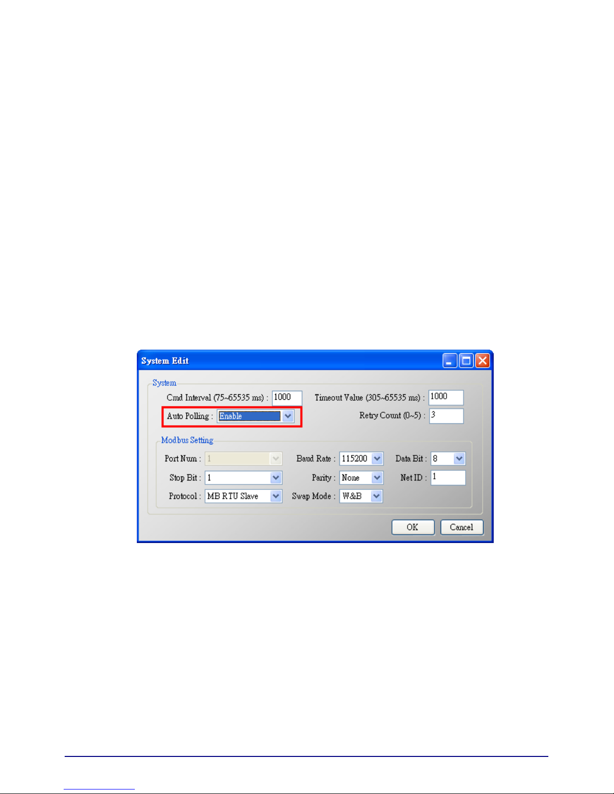
1. “System Edit” window:
Page 59

Figure 40: The “System Edit” window
It is used to set the comm. parameters of HART and Modbus.
(1) cmd interval (75~65535 ms): The polling interval of HART Cmd.
EX: HART Cmd 1 request HART Cmd1 response wait (cmd interval) HART
Cmd 2 request HART Cmd 2 response wait (cmd interval) …
(2) timeout value (305~65535 ms): The timeout value of HART Cmd.
(3) Auto polling: If the function is enabled, HRT-7(3)10 will execute all HART polling Cmd
automatically.
(4) Retry count (0~5): When HART comm. error happened, HRT-710 will re-send the
HART Cmd for “Retry count” times.
(5) The following are the Com Port comm. setting of HRT-7(3)10.
[1] Baud Rate: 1200~115200 bps.
[2] Data Bits: 7 or 8.
[3] Stop Bits: 1 or 2
[4] Parity: None / Odd / Even.
[5] Net ID: 1~247.
[6] Protocol: MB RTU Slave or MB ASCII Slave.
[7] Swap mode: None / Byte / Word / W&B (The swap mode of Modbus comm.)
EX: 2 words data (0x1234, 0x5678) from HRT-710. Users can set the swap mode for
different data format.
Swap mode Data
None 0x1234 0x5678
Byte 0x3412 0x7856
HR
T-710 / HRT-310 User Manual Version 1.31 Page:
59
Copyright © 2017 ICP DAS Co., Ltd. All Rights Reserved E-mail: service@icp das.com
Page 60

HR
T-710 / HRT-310 User Manual Version 1.31 Page:
60
Copyright © 2017 ICP DAS Co., Ltd. All Rights Reserved E-mail: service@icp das.com
Swap mode Data
Word 0x5678 0x1234
W&B 0x7856 0x3412
2. “Module Edit” window:
Figure 41: The “Module Edit” window
It is used to set the comm. mode for HART devices.
(1) Channel: 0~7. (Only channel 0 supports now)
(2) Auto Configure: If enables this function, HRT-7(3)10 will detect the “frame type”,
“address”, “preambles”, “manufacturer ID”, “device type” and “device ID” of HART
device automatically.
[Note] If enables this function, just supports HART “Point to Point” mode.
(3) Frame type: Short or Long frame.
(4) Master type: Primary or Secondary Master.
[Note] In general, HRT-7(3)10 should be the “Primary Master”.
(5) Network mode: “Point to Point” or “Multi-drop” mode.
Note :
[1] “Point to Point”: Only one HART slave device in HART bus.
[2] “Multi-drop”: More than one HART devices can be in HART bus.
(6) Address: 0~15.
Note :
[1] If the address of HART device is 0, it means in the “Point to Point” mode.
[2] If the address of HART device is between 1 and 15, it means in the “Multi-Drop”
mode.
Page 61

(7) Preambles: 5~20.
(8) Get identifier automatically: If the frame type of HART slave device is long frame, users
can enable this function to get unique ID automatically by short frame address.
(9) Manufacturer ID: Users can set the manufacturer ID for HART device. If the frame type
is “short”, users can omits this setting.
(10) Device type: Users can set the device type for HART device. If the frame type is
“short”, users can omits this setting.
(11) Device ID: Users can set the device ID for HART device. If the frame type is “short”,
users can omits this setting.
(12) Cmd 0 mode: Disable / Initial / Polling.
(13) Cmd 3 mode: Disable / Initial / Polling.
Disable: module will not execute the default HART Cmd.
Initial: module will execute the default HART Cmd automatically when in “Initial” mode.
Polling: module will execute the default HART Cmd automatically when in “Operation”
mode.
3. “User CMD Edit” window:
Figure 42: The command window
It is used to set the comm. parameter for HART User CMD.
(1) Command Num.: Set the HART command number.
(2) Mode: Initial / Polling / Manual.
Initial: The module will run this command in initial mode.
Polling: The module will run this command in operation mode.
Manual: The module will run this command by manual.
(3) Format: Normal / Simple. (Data exchange format between HART and Modbus)
[1] Normal: When read / write HART data by Modbus, the data format is HART
standard command format.
HR
T-710 / HRT-310 User Manual Version 1.31 Page:
61
Copyright © 2017 ICP DAS Co., Ltd. All Rights Reserved E-mail: service@icp das.com
Page 62

[2] Simple: When read / write HART data by Modbus, the data format is simple format
defined by HRT-7(3)10. The detailed description, please refer to the appendix B -
command format. (In this mode, the HMI or SCADA software can read or write
HART data and don’t need to process any data. Now, it is only supported HART
command number: 1, 2 and 3.)
(4) In Size: Set the input data length of HART command.
Note: The size includes 2 bytes response code and data size of HART command. (Ex:
HART Cmd 0 = 2(response code) +12 =14)
(5) Out Size: Set the output data length of HART command.
(Ex: HART command 0 = 0, HART command 6 = 1)
5.3.4.4 Default Output Data
Figure 43: The window of default output data
It is used to set the default value for all UserCMD output data.
(1) Click the left “User CMD” item and if the output length of the “User CMD” is not zero,
then the occupied address will be blue in the right window.
(2) Double click the address field and it will show the “Data Edit” window to set the default
value.
HR
T-710 / HRT-310 User Manual Version 1.31 Page:
62
Copyright © 2017 ICP DAS Co., Ltd. All Rights Reserved E-mail: service@icp das.com
Page 63

5.3.4.5 Address Map
Figure 44: The window of address map
It is used to show the MB address for all User CMD.
(1) Click the left “User CMD” item and the occupied address of the “User CMD” will be blue
in the right Modbus AO or Modbus AI table.
(2) The data of Modbus AI table can be read by MB Function Code 4.
(3) The data of Modbus AO table can be read by MB Function Code 3 and written by MB
Function Code 6 or 16.
[ Note ]
The MB address of the default command is fixed, so users can refer to section 4.3 –
“Modbus / HART Mapping Table” to get the address.
HR
T-710 / HRT-310 User Manual Version 1.31 Page:
63
Copyright © 2017 ICP DAS Co., Ltd. All Rights Reserved E-mail: service@icp das.com
Page 64

5.3.4.6 Device Diagnostic
Figure 45: The window of device diagnostic
It is used to show the status of HART command in HRT-7(3)10.
(1) Click the left “User CMD” item and the icon of the item will show the status described
as below:
1.
It means no error.
2.
It means the command has never been executed.
3. It means the command has error and the error status shows at the right
side of the window.
4. It means the item is selected.
(2) “Status Update” button: Refresh the status of HART Cmd.
(3) “Record” button: HRT-7(3)10 will record the latest error command and save to “Record
1~3”. Users can get these records by click “Record 1”, “Record 2” and “Record 3”
button.
HR
T-710 / HRT-310 User Manual Version 1.31 Page:
64
Copyright © 2017 ICP DAS Co., Ltd. All Rights Reserved E-mail: service@icp das.com
Page 65

5.3.4.7 Through Mode
Figure 46: The window of through mode
It is used to send / receive HART command directly.
EX: Send a short frame HART command 0 and receive the response.
(1) In “Send” field, fill in the data - “0xFF 0xFF 0xFF 0xFF 0xFF 0x02 0x80 0x00 0x00” and
then click “Send” button to send HART Cmd.
(2) Click “Update” button to show the response of HART device.
Warning: Before using through mode function, please check the below items:
(1) The “RUN” LED is always on.
(2) The “auto polling” function is disabled. (Refer to section 5.3.4.2 – “The Basic Operation
of System item”)
HR
T-710 / HRT-310 User Manual Version 1.31 Page:
65
Copyright © 2017 ICP DAS Co., Ltd. All Rights Reserved E-mail: service@icp das.com
Page 66

5.3.4.8 Format Translation
Figure 47: The window of format translate
Here we provide some tools for HART communication. “Packed ASCII Translate” tool can
convert “Packed ASCII” into ASCII format. “IEEE754 Translate” tool can convert
“IEEE754” into byte format.
(1) “Packed ASCII Translate”: It can be used to convert between “Packed ASCII” and
“ASCII” format.
Figure 48: The window of packed ASCII translate
(2) “IEEE 754 Translate”: It can be used to convert between “IEEE754” and “DWORD”
format.
Figure 49: The window of IEEE754 translate
HR
T-710 / HRT-310 User Manual Version 1.31 Page:
66
Copyright © 2017 ICP DAS Co., Ltd. All Rights Reserved E-mail: service@icp das.com
Page 67

5.3.4.9 About
Figure 50: The window of About
HR
T-710 / HRT-310 User Manual Version 1.31 Page:
67
Copyright © 2017 ICP DAS Co., Ltd. All Rights Reserved E-mail: service@icp das.com
Page 68

5.4 Establish connection with module
The connection between HG_Tool and HRT-7(3)10 is shown as Figure 51.
Figure 51: The connection of Utility and HRT-710
Please follow the below steps to establish connection with HRT-7(3)10.
Step 1: Wire COM Port of PC to RS-232 port of HRT-7(3)10
Step 2: Run “HG_Tool” on PC.
Figure 52: Run “HG_Tool” Utility
Step 3: Set COM Port comm. setting of HG_Tool the same as HRT-7(3)10
The default settings of HRT-7(3)10 are as below.
[1] protocol: MB RTU
[2] Net ID: 1
[3] baud rate: 115200 bps
[4] data bits: 8 ; stop bits: 1 ; parity: None.
HR
T-710 / HRT-310 User Manual Version 1.31 Page:
68
Copyright © 2017 ICP DAS Co., Ltd. All Rights Reserved E-mail: service@icp das.com
Page 69

Figure 53: Com Port settings of the utility
Step 4: Click “Connect” button.
Figure 54: Click “Connect” button
HR
T-710 / HRT-310 User Manual Version 1.31 Page:
69
Copyright © 2017 ICP DAS Co., Ltd. All Rights Reserved E-mail: service@icp das.com
Page 70

Step 5: If the connection is successful, then the traffic light shows green.
Figure 55: Connection status
HR
T-710 / HRT-310 User Manual Version 1.31 Page:
70
Copyright © 2017 ICP DAS Co., Ltd. All Rights Reserved E-mail: service@icp das.com
Page 71

6. Troubleshooting
The troubleshooting list can help users to resolve the problems when using the HRT-7(3)10. If
the problem still can't be solved, please E-mail to ICP DAS : service@icpdas.com.
[ Table 7: Errors and Solutions ]
No Trouble state Solution
1
The 'PWR' LED of is always
off
Please check the power wiring of HRT-7(3)10 and the voltage is
between 10~30Vdc.
2
The 'RUN' LED always
flashes.
Flash once per second:
[ Reason ]
Module is always in initial mode. It means HRT-7(3)10 can’t
connect to all the configured HART devices.
[ Resolve ]
1. Please check the wiring between HRT-7(3)10 and HART
devices and the configuration of HRT-7(3)10.
2. If the problem still exists, please connect to only one HART
device. Then set the configuration of HRT-7(3)10 again and
reboot module to test it again.
Flash once per half second:
[ Reason ]
HRT-7(3)10 has received the burst frame from HART device.
[ Resolve ]
In burst mode, the HRT-710 must work at the “Point to Point”
network and disable the “auto polling” function.
3
The 'ERR' LED always
flashes.
[ Reason ]
It means some errors happened in the user CMD.
[ Resolve ]
Users can get the error status by using the “Device Diagnostic”
function of HG_Tool.
HR
T-710 / HRT-310 User Manual Version 1.31 Page:
71
Copyright © 2017 ICP DAS Co., Ltd. All Rights Reserved E-mail: service@icp das.com
Page 72

7. Dimensions
[ HRT-710 ]
HR
T-710 / HRT-310 User Manual Version 1.31 Page:
72
Copyright © 2017 ICP DAS Co., Ltd. All Rights Reserved E-mail: service@icp das.com
Page 73

HR
T-710 / HRT-310 User Manual Version 1.31 Page:
73
Copyright © 2017 ICP DAS Co., Ltd. All Rights Reserved E-mail: service@icp das.com
Page 74

[ HRT-310 ]
HR
T-710 / HRT-310 User Manual Version 1.31 Page:
74
Copyright © 2017 ICP DAS Co., Ltd. All Rights Reserved E-mail: service@icp das.com
Page 75

HR
T-710 / HRT-310 User Manual Version 1.31 Page:
75
Copyright © 2017 ICP DAS Co., Ltd. All Rights Reserved E-mail: service@icp das.com
Page 76

8. FAQ
Q01 : How to add HART devices to HRT-710 ?
A01:
1. Add “Only One” HART device : (Ex : Add ABB AS800 HART device)
[ Step 1 ] Connect to HRT-710 with “HG_Tool” utility.
(1) Set the com port parameters.
(2) Click the “Connect” button to connect to HRT-710 module like Figure 1-1.
Figure 1-1 Connect to HRT-710
[ Step 2 ] Delete the default HART device setting in HRT-710
HR
T-710 / HRT-310 User Manual Version 1.31 Page:
76
Copyright © 2017 ICP DAS Co., Ltd. All Rights Reserved E-mail: service@icp das.com
Page 77

=>
Figure 1-2 Delete the default setting of HRT-710.
[ Step 3 ] Add the new HART device setting
(1) Method 1 => Choose “Auto Configure” option to be Enable like Figure 1-3.
Figure 1-3 Add new HART device setting (Auto Config : Enable)
(2) Method 2 => Choose “Auto Configure” option to be Disable like Figure 1-4.
HR
T-710 / HRT-310 User Manual Version 1.31 Page:
77
Copyright © 2017 ICP DAS Co., Ltd. All Rights Reserved E-mail: service@icp das.com
Page 78

Figure 1-4 Add new HART device setting (Auto Config : Disable)
[ Step 4 ] Save the HART device setting to HRT-710
(1) Click the “Save to Device” button to save the new HART device setting to HRT-710
like Figure 1-5.
Figure 1-5 “Save to Device” function
2. Add “More than One” HART devices : (Ex : Add two HART devices)
HR
T-710 / HRT-310 User Manual Version 1.31 Page:
78
Copyright © 2017 ICP DAS Co., Ltd. All Rights Reserved E-mail: service@icp das.com
Page 79

(1) Foxboro I/A Pressure (Addr=1)
(2) ABB AS800 (Addr=2)
[ Note ] Users need to set the address of every HART device between 1 to 15 first. The
address 0 is not allowed in HART multi-drop network.
[ Step 1 ] Connect to HRT-710 with “HG_Tool” utility.
[ Step 2 ] Delete the default HART device setting in HRT-710
=> These above two steps are the same with those of the “Only One” HART device.
[ Step 3 ] Add two new HART device setting
(1) Click “Auto Configure” option to be Disable like Figure 1-6.
HR
T-710 / HRT-310 User Manual Version 1.31 Page:
79
Copyright © 2017 ICP DAS Co., Ltd. All Rights Reserved E-mail: service@icp das.com
Page 80

Figure 1-6 Add new HART device setting
[ Step 4 ] Save the HART device setting to HRT-710
(1) Click the “Save to Device” button to save the new HART device setting to HRT-710
like Figure 1-7.
Figure 1-7 “Save to Device” function
HR
T-710 / HRT-310 User Manual Version 1.31 Page:
80
Copyright © 2017 ICP DAS Co., Ltd. All Rights Reserved E-mail: service@icp das.com
Page 81

Q02 : How to make sure that HRT -710 get s the HART device data correctly ?
A02:
After adding HART device setting to HRT-710 module (refer to the steps of Q01), please
follow the steps.
(1) Make sure connecting to HRT-710 with HG_Tool successfully and then click “Device
Information” button like Figure 2-1.
Figure 2-1 “Device Information” screen
[ Check I/O Data of the Default CMD(0) ]
(2) Right click the button of mouse on the “Default CMD(0)” item and choose the “Basic
operation” option to open the “I/O Data” screen of the “Default CMD(0)” like Figure 2-2.
HR
T-710 / HRT-310 User Manual Version 1.31 Page:
81
Copyright © 2017 ICP DAS Co., Ltd. All Rights Reserved E-mail: service@icp das.com
Page 82

Figure 2-2 The “Basic operation” of the “Default CMD(0)”
(3) The I/O Data of the “Default CMD(0)” is OK like Figure 2-3.
Figure 2-3 The I/O Data screen of the “Default CMD(0)” => OK
(4) The I/O Data of the “Default CMD(0)” is NG like Figure 2-4.
Figure 2-4 The I/O Data screen of the “Default CMD(0)” => NG
[ Check I/O Data of the Default CMD(3) ]
(5) Right click the button of mouse on the “Default CMD(3)” item and choose the “Basic
operation” option to open the “I/O Data” screen of the “Default CMD(3)” like Figure 2-5.
HR
T-710 / HRT-310 User Manual Version 1.31 Page:
82
Copyright © 2017 ICP DAS Co., Ltd. All Rights Reserved E-mail: service@icp das.com
Page 83

Figure 2-5 The “Basic operation” of the “Default CMD(3)”
(6) The I/O Data of the “Default CMD(3)” is OK like Figure 2-6.
Figure 2-6 The I/O Data screen of the “Default CMD(3)” => OK
(7) The I/O Data of the “Default CMD(3)” is NG like Figure 2-7.
Figure 2-7 The I/O Data screen of the “Default CMD(3)” => NG
=> If the I/O data of the “Default CMD(0)” and “Default CMD(3)” is ok, it means that the
communication between HRT-710 and HART devices is ok.
HR
T-710 / HRT-310 User Manual Version 1.31 Page:
83
Copyright © 2017 ICP DAS Co., Ltd. All Rights Reserved E-mail: service@icp das.com
Page 84

Q03 : How to map HART device CMD(3) data directly to SCADA or HMI ?
A03:
(1) Make sure that the communication between HRT-710 and HART device is ok. (Refer to
the steps of Q02)
(2) Set “Swap Mode” of system setting in HRT-710 to be “W&B”.
[1] In “Device Configuration” screen, right click the button of mouse on “System” item and
click the “Edit” option to open “System Edit” screen like Figure 3-1.
Figure 3-1 Open “System Edit” screen
[2] Set the “Swap mode” item to be “W&B” and click “OK” button like Figure 3-2.
HR
T-710 / HRT-310 User Manual Version 1.31 Page:
84
Copyright © 2017 ICP DAS Co., Ltd. All Rights Reserved E-mail: service@icp das.com
Page 85

Figure 3-2 Set “Swap mode” to be “W&B”
[3] Click the “Save to Device” button to save the new system setting to HRT-710 like Figure
3-3.
Figure 3-3 “Save to Device” function
(3) Check the firmware version of HRT-710 like Figure 3-4.
HR
T-710 / HRT-310 User Manual Version 1.31 Page:
85
Copyright © 2017 ICP DAS Co., Ltd. All Rights Reserved E-mail: service@icp das.com
Page 86

Figure 3-4 Firmware Version of HRT-710
(4) Follow the below steps according to the different firmware version of HRT-710.
[ 4.1 - The firmware version of HRT-710 is v1.5 or newer ]
[1] In firmware v1.5 or newer, HRT-710 provides the MB Address 1300 ~ 1459 (Default
CMD(3)(S) Data for Module 0 ~ 15 in HRT-710 => The detailed information refers to the
sector 4.3 of users’ manual) and users can map the CMD(3) data of HART device to
SCADA directly with these Modbus address 1300 ~ 1459.
[2] For the “Default CMD(3)(S) data of Module 0” in HRT-710, the mapped MB address is
1300 ~ 1309. The below MB/RTU client will use the “ModScan” and “Modbus Poll” tool
to show the CMD(3) data of HART device by polling Modbus address 1300 ~ 1309.
<1> Confirm the connection between HG_Tool and HRT-710 is disconnected.
<2> Make sure the HRT-711 is in the Normal operation. ( Set the “Dip Switch” on the
back of HRT-711 to be “Normal” and reboot HRT-711. )
<3> Set the “Display” mode to be “Float” format as Figure 3-5
Figure 3-5 Modbus display format
<4> Fill the connection parameters and click “OK” button to connect to HRT-711, e.g.
Figure 3-6
HR
T-710 / HRT-310 User Manual Version 1.31 Page:
86
Copyright © 2017 ICP DAS Co., Ltd. All Rights Reserved E-mail: service@icp das.com
Page 87

Figure 3-6 Connection parameters
<5> The CMD(3) data of HART device is successfully read, e.g. Figure 3-7
Figure 3-7 The CMD(3) data of HART device
HR
T-710 / HRT-310 User Manual Version 1.31 Page:
87
Copyright © 2017 ICP DAS Co., Ltd. All Rights Reserved E-mail: service@icp das.com
Page 88

[ Note ] ModScan designed to use PLC address (Base 1), so the polling address
entered needs to be 1301. Users can make sure the actual polling address is
[05][14] (1300) by selecting “Show Traffic” of the “Display Option” within
“Setup” menu after successful connected, shown as Figure 3-8
Figure 3-8 The actual polling Modbus address
<6> Check and modify Modbus Poll Address Base types and display formats like Figure
3-9.
Figure 3-9 Address Base types and display formats
HR
T-710 / HRT-310 User Manual Version 1.31 Page:
88
Copyright © 2017 ICP DAS Co., Ltd. All Rights Reserved E-mail: service@icp das.com
Page 89

<7> Set the “Read/Write Definition” of Modbus Poll like Figure 3-10.
Figure 3-10 “Read/Write Definition” of Modbus Poll tool
[ Note ] The polling address is 1300 in this case because “Protocal Address (Base 0)”
has been selected for Modbus Poll. If “PLC Address Poll (Base 1)” has been
selected instead, then the address needs to be set as 1301. Users can make
sure the actual polling address is [05][14] (1300) by checking the
“Communication” dialog from “Display” menu after successful connected,
shown as Figure 3-11
HR
T-710 / HRT-310 User Manual Version 1.31 Page:
89
Copyright © 2017 ICP DAS Co., Ltd. All Rights Reserved E-mail: service@icp das.com
Page 90

Figure 3-11 Polling address from “Communication Traffic”
<8> Set the “Com Port” parameters and click “OK” button to connect to HRT-710 like
Figure 3-12.
Figure 3-12 Com Port Parameters of “Modbus Poll” tool
<9> The CMD(3) data of HART device is shown like Figure 3-13.
HR
T-710 / HRT-310 User Manual Version 1.31 Page:
90
Copyright © 2017 ICP DAS Co., Ltd. All Rights Reserved E-mail: service@icp das.com
Page 91

Figure 3-13 The CMD(3) data of HART device
[ 4.2 - The firmware version of HRT-710 is older than v1.5 ]
[1] Add “User CMD(3)” with “Simple” format and then click “Save to Device” to save the new
HART device setting to HRT-710 like Figure 3-14. The mapped Modbus start address
and length of User CMD(3) data can be found in “Cmd In address” and “Cmd In size”
field. In the example, they are 0 and 20.
HR
T-710 / HRT-310 User Manual Version 1.31 Page:
91
Copyright © 2017 ICP DAS Co., Ltd. All Rights Reserved E-mail: service@icp das.com
Page 92

Figure 3-14 Add “User CMD(3)” to HRT-710
[2] The below MB/RTU client will use the “Modbus Poll” tool to show the CMD(3) data of
HART device by polling Modbus address 0 ~ 9.
<1> Confirm the connection between HG_Tool and HRT-710 is disconnected.
<2> Set the “Modbus” parameters like Figure 3-15.
HR
T-710 / HRT-310 User Manual Version 1.31 Page:
92
Copyright © 2017 ICP DAS Co., Ltd. All Rights Reserved E-mail: service@icp das.com
Page 93

Figure 3-15 Modbus Parameters of “Modbus Poll” tool
<3> Set the “Display” mode to be “Float” format like Figure 3-16.
Figure 3-16 “Float” format of “Modbus Poll” tool
<4> Set the “Com Port” parameters and click “OK” button to connect to HRT-710 like
Figure 3-17.
HR
T-710 / HRT-310 User Manual Version 1.31 Page:
93
Copyright © 2017 ICP DAS Co., Ltd. All Rights Reserved E-mail: service@icp das.com
Page 94

Figure 3-17 Com Port Parameters of “Modbus Poll” tool
<5> The CMD(3) data of HART device is shown like Figure 3-18.
Figure 3-18 The CMD(3) data of HART device
[3] The below MB/RTU client will use the “ModScan” tool to show the CMD(3) data of HART
device by polling Modbus address 1300 ~1309.
HR
T-710 / HRT-310 User Manual Version 1.31 Page:
94
Copyright © 2017 ICP DAS Co., Ltd. All Rights Reserved E-mail: service@icp das.com
Page 95

[ Note ]
1. The simple CMD(3) data format and value are shown as below.
[ Index ] [ Format ] [ Description ]
Byte 00~03: float Primary Variable Current
Byte 04~07: float Primary Variable
Byte 08~11: float Secondary Variable
Byte 12~15: float Tertiary Variable
Byte 16~19: float 4th Variable
The 30001 and 30002 registers mean “Primary Variable Current (20.124636)”
The 30003 and 30004 registers mean “Primary Variable (0.385210)”
The 30005 and 30006 registers mean “Secondary Variable (23.494614)”
The 30007 and 30008 registers mean “Tertiary Variable (100.778976)”
The 30009 and 30010 registers mean “4th Variable (0)”
HR
T-710 / HRT-310 User Manual Version 1.31 Page:
95
Copyright © 2017 ICP DAS Co., Ltd. All Rights Reserved E-mail: service@icp das.com
Page 96

Q04 : How to update the firmware of HRT-710 ?
A04:
[ For HRT-710 hardware v1.1 or firmware v1.1 or below ]
The firmware update function is not supported for users and please contact your local
dealer.
[ For HRT-710 hardware v1.2 and firmware v1.2 or newer ]
The firmware update function is supported for users. Please follow the below steps.
(1) Download the newest firmware of HRT-710. (Download from
ftp://ftp.icpdas.com/pub/cd/fieldbus_cd/hart/gateway/hrt-710/firmware/)
(2) Turn off the power and open the shell of HRT-710. Then connect the pin 2 & 3 of JP5
together like Figure 4-1.
Figure 4-1 Connect pin 2 & 3 of JP5 together
(3) Connect RS-232 cable between PC and HRT-710 and turn on the power of HRT-710
(LED 1,2,3 will flash every second => Firmware Update Mode) like Figure 4-2.
HR
T-710 / HRT-310 User Manual Version 1.31 Page:
96
Copyright © 2017 ICP DAS Co., Ltd. All Rights Reserved E-mail: service@icp das.com
Page 97

Figure 4-2 RS-232 Connection between PC and HRT-710
(4) Run “FW_Update_Tool” like Figure 4-3 (Download from :
ftp://ftp.icpdas.com/pub/cd/fieldbus_cd/hart/gateway/utilities/fw_tool/ ).
[1] Choose “COM” option and select “Com Port number”.
[2] Click “Browser” button to choose the firmware of HRT-710.
[3] Click “Firmware Update” button to start firmware update process.
[4] Wait for "Firmware Update Success" message.
Figure 4-3 “FW_Update_Tool”
HR
T-710 / HRT-310 User Manual Version 1.31 Page:
97
Copyright © 2017 ICP DAS Co., Ltd. All Rights Reserved E-mail: service@icp das.com
Page 98

(5) Turn off the power and connect the pin 1 & 2 of JP5 together like Figure 4-4.
Figure 4-4 Connect pin 1 & 2 of JP5 together
(6) Close the shell and turn on the power of HRT-710. Then users can check the firmware
version of HRT-710 by using “HG_Tool” like Figure 4-5.
Figure 4-5 Firmware Version of HRT-710
HR
T-710 / HRT-310 User Manual Version 1.31 Page:
98
Copyright © 2017 ICP DAS Co., Ltd. All Rights Reserved E-mail: service@icp das.com
Page 99

Q05 : How to read HART device CMD1 data with standard format by
Modbus ?
A05:
(1) By using “HG_Tool” to add “User CMD(1)” of HART device and save settings to
HRT-710. The Modbus start address and length of the “User CMD(1)” will show in the
“Cmd In address” and “Cmd In size” field like Figure 5-1. In the example they are 0 and
7 (byte count=7 => word count=4).
HR
T-710 / HRT-310 User Manual Version 1.31 Page:
99
Copyright © 2017 ICP DAS Co., Ltd. All Rights Reserved E-mail: service@icp das.com
Page 100

Figure 5-1 Add “User CMD(1)” of HART device to HRT-710
(2) The below demo will use the free MB/RTU tool provided by ICP DAS to show HART
command 1 data. (Download from
http://ftp.icpdas.com.tw/pub/cd/8000cd/napdos/modbus/modbus_utility/)
(3) Run “MB/RTU” tool. Set the com port settings the same with HART-710 (Baud Rate /
Data Bits / Stop Bits / Parity) and then click “Open” button to connect to HRT-710 like
Figure 5-2.
(4) Input “1 4 0 0 0 4” in “Command” field and click “Send Command” button to send the
modbus command. The HART command 1 data will be received in “Responses” field =>
“01 04 08 00 00 3E 0C 20 C5 00 A4 2A 94” like Figure 5-2.
Send Modbus Command : 01 04 00 00 00 04 F1 C9
Get Response : 01 04 08 00 00 3E 0C 20 C5 00 A4 2A 94
HR
T-710 / HRT-310 User Manual Version 1.31 Page:
100
Copyright © 2017 ICP DAS Co., Ltd. All Rights Reserved E-mail: service@icp das.com
 Loading...