

Page 1

HDS
HART Device Simulator
User’s Manual
(v1.09)
Warranty
All products manufactured by ICP DAS are under warranty regarding
defective materials for a period of one year from the date of delivery to the
original purchaser.
Warning
ICP DAS assumes no liability for damages resulting from the use of
this product. ICP DAS reserves the right to change this manual at any time
without notice. The information furnished by ICP DAS is believed to be
accurate and reliable. However, no responsibility is assumed by ICP DAS
for its use, or for any infringements of patents or other rights of third
parties resulting from its use.
Copyright
Copyright 2015 by ICP DAS. All rights are reserved.
Trademark
The names used for identification only may be registered trademarks
of their respective companies.
HDS (HART Device Simulator) User’s Manual (Ver 1.09, 2020/11/19) ------------- 1
Page 2

Table of Contents
1. Introduction .......................................................................... 3
1.1 HDS Features .................................................................................... 3
1.2 HDS Information ................................................................................ 4
2. HDS Tool ............................................................................... 5
2.1 HDS Operation ................................................................................... 5
2.1.1 ComPort ........................................................................................... 5
2.1.2 Parameter of HART Simulation Device ................................ ............ 5
2.1.3 System Function .............................................................................. 7
2.1.4 I-7547 Function .............................................................................. 10
2.2 HDS Other Function .......................................................................... 11
2.2.1 HART Supported Command............................................................ 11
3. FAQ ...................................................................................... 12
Q01. Run the HDS tool step by step? .................................................................. 12
Q02. How to modify the parameters for HART simulated device? ....................... 14
Q03. How to use HDS to virtually transfer Modbus device to HART device? ...... 18
Q04. How to use HART Device-Specific commands ........................................... 21
Q05. How to change CMD48 parameters setting ................................................ 25
Q06. How to simulate HART 7.0 device by HDS ................................................. 26
Q07. How to use Modbus to communicate with HDS ? ....................................... 28
Q08. How to response HART specific command 158 in HDS ? ........................... 29
Q09. How to simulate the abnormal status of HDS ?........................................... 31
Q10. How to enable/disable the burst mode of HDS ? ........................................ 34
Q11. How to set HART burst command number of HDS ? .................................. 35
4. Version History ................................................................... 38
HDS (HART Device Simulator) User’s Manual (Ver 1.09, 2020/11/19) ------------- 2
Page 3
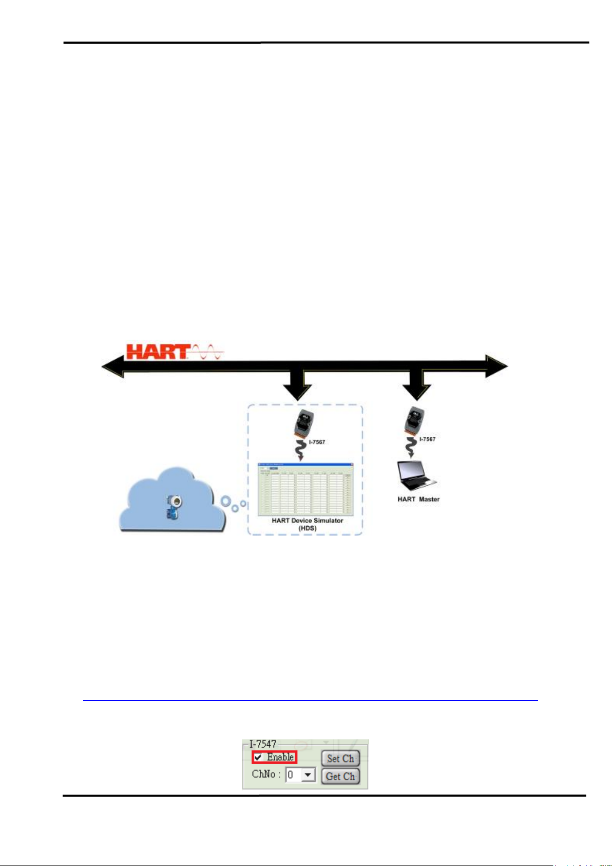
1. Introduction
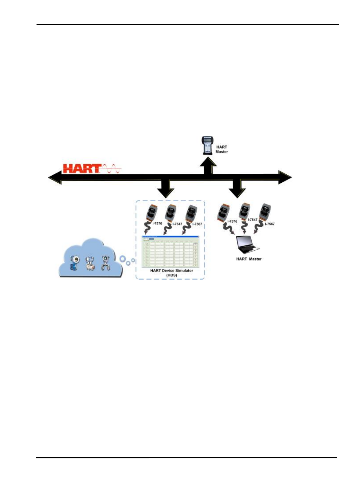
HART Device Simulator (called HDS) is the HART device simulation
software developed by ICP DAS. It can be used to simulate multi HART
slave devices simultaneously to exchange data with HART master device
by using ICP DAS HART converter (like: I-7567 / I-7570 / I-7547)
connected to any COM port (USB / 232 / 485 / Ethernet). By this way,
users can develop or verify the HART master program without any HART
slave device. The below figure is the application of HDS.
Figure 1-1 : HDS Application
1.1 HDS Features
Free HART slave device simulation software
(Must work with one of ICP DAS HART converter: I-7567/ I-7570/ I-7547)
Support a lot of HART commands (like: CMD0 / 1 / 2 / 3 …)
Provide the setting for the long frame address of HART device.
Provide the setting for the value and unit of HART command 3.
Support 16 HART devices simulation simultaneously (address 0 ~ 15).
Exchange data with HART master device by using ICP DAS HART
converter (like: I-7567 / I-7570 / I-7547)
Support HART communication data log.
Provide the “adjustable” HART device status bit
HDS (HART Device Simulator) User Manual (Ver 1.09, 2020/11/19) ------------- 3
Page 4
1.2 HDS Information
Compatible with command revision 5, 6, 7 of HART protocol.
When the COM port is open, the HDS will listen for the incoming
requests and response data.
Only the HART simulation device with the “Enabled” option checked will
response data.
The field of the “Short Frame Address” is fixed.
The field of the “Long Frame Address” with 5 bytes can be set to
simulate the different HART manufacturer’s slave device.
All the HART communication data can be logged to file.
The four main values and units of PV / SV / TV /QV of HART command
3 can be set for every HART simulation device.
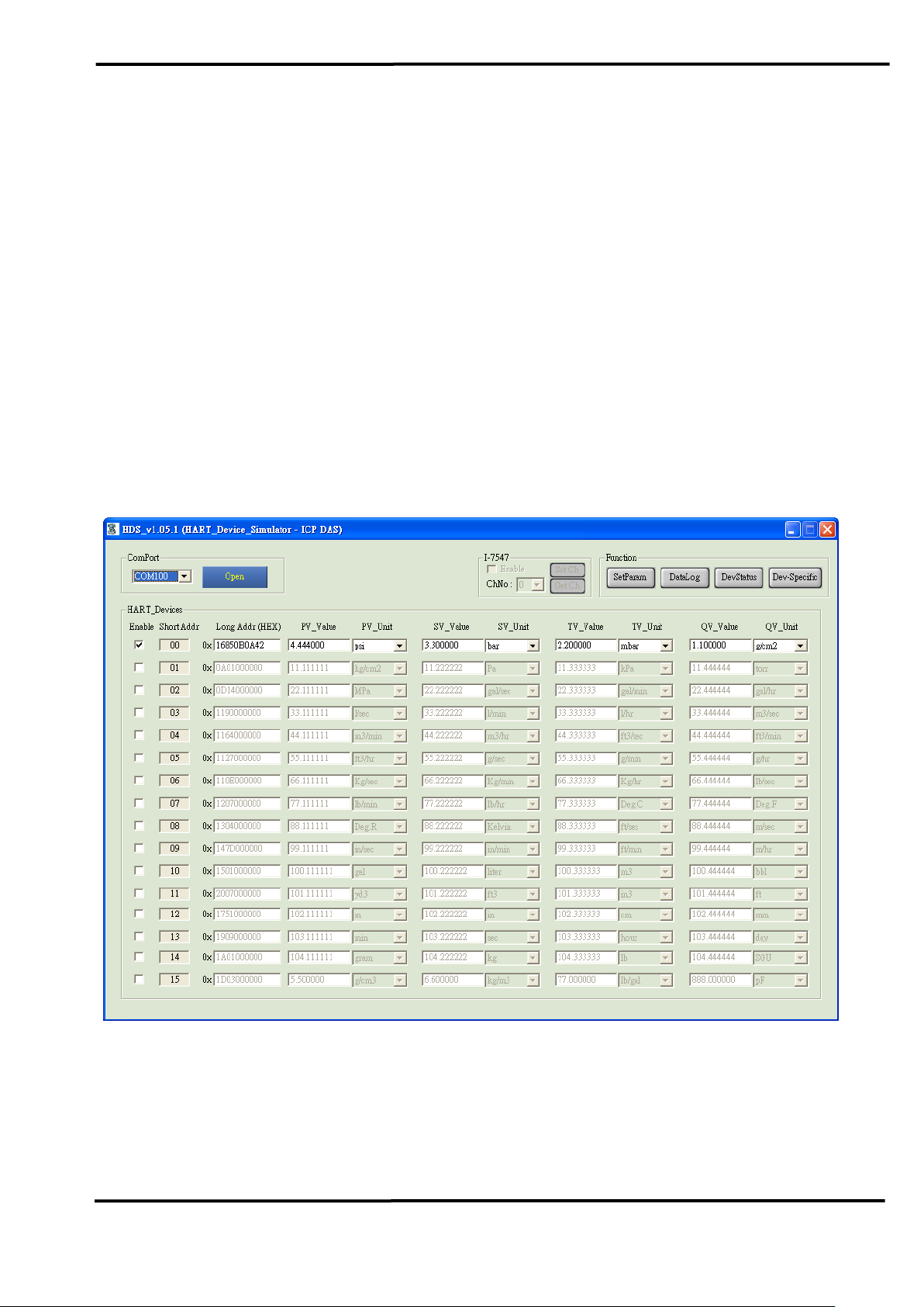
Figure 1-2 : HDS Tool
HDS (HART Device Simulator) User Manual (Ver 1.09, 2020/11/19) ------------- 4
Page 5
2. HDS Tool
The HDS software includes the below files.
(1) HDS.exe => The main program.
(2) HDS.ini => The record file for parameters.
=> Users can execute the “HDS.exe” to run HDS program.
=> HDS software can be downloaded from :
http://ftp.icpdas.com/pub/cd/fieldbus_cd/hart/converter/hds/software/.。
2.1 HDS Operation
Execute the HDS tool.
Figure 2-1: HDS Main Screen
2.1.1 ComPort
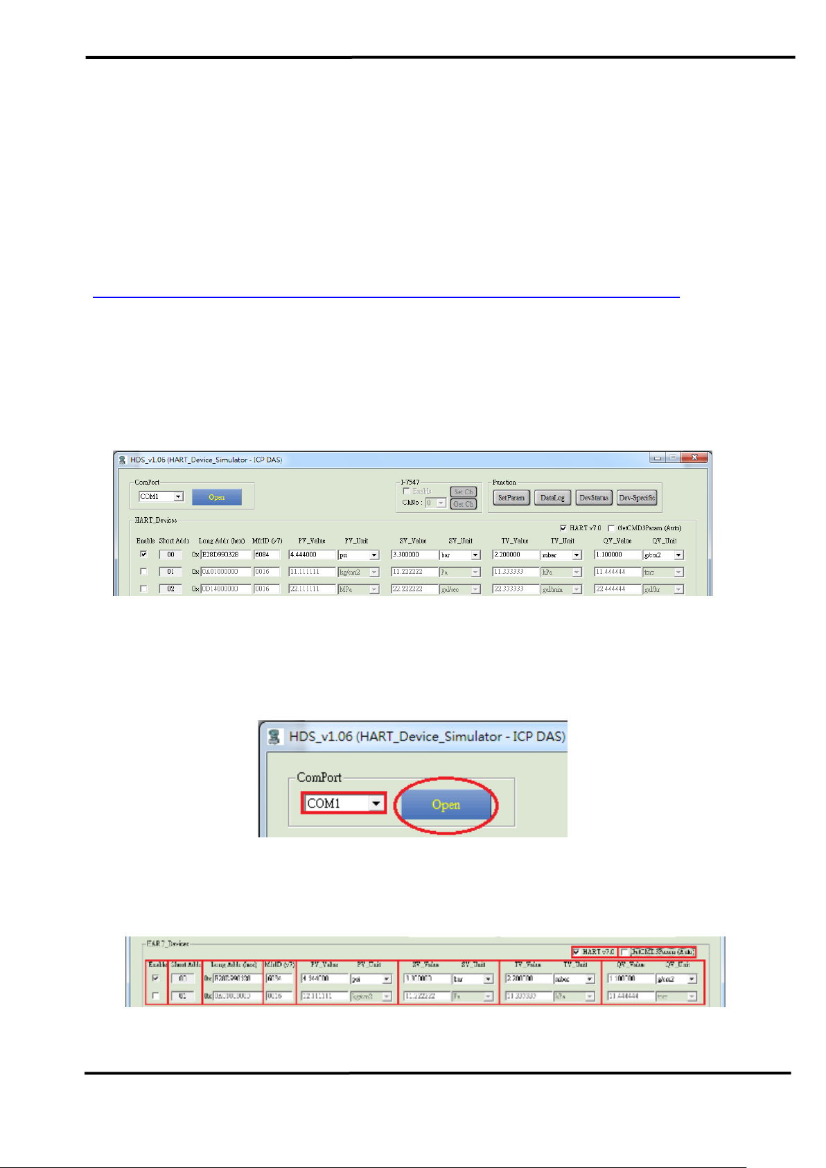
Choose the “ComPort” number and click the “Open” button.
Figure 2-2: Open the “ComPort”
2.1.2 Parameter of HART Simulation Device
HDS (HART Device Simulator) User Manual (Ver 1.09, 2020/11/19) ------------- 5
Page 6

(1) “HART v7.0” option : (Available after version v1.06)
=> If checked, “MfrID” field will be enabled
(2) “GetCMD3Param” option : (Available after version v1.06)
=> If checked, HDS will load CMD3 parameters settings from INI file
(3) “Enable” option :
=> If checked, the corresponding HART simulation device will be enabled.
(4) “Short Addr” field : (fixed, decimal)
=> The Short Frame Address of HART simulation device.
(5) “Long Addr (HEX)” field : (can be set, hex)
=> The Long Frame Address of HART simulation device.
(6) “MfrID” field : (can be set, hex)
=> Enabled if “HART v7.0” checked, the manufacturer ID for HART v7.0
(7) “PV_Value / PV_Unit” field : (can be set)
=> The PV value and unit of HART simulation device.
(8) “SV_Value / SV_Unit” field : (can be set)
=> The SV value and unit of HART simulation device.
(9) “TV_Value / TV_Unit” field : (can be set)
=> The TV value and unit of HART simulation device.
(10) “QV_Value / QV_Unit” field : (can be set)
=> The QV value and unit of HART simulation device.
HDS (HART Device Simulator) User Manual (Ver 1.09, 2020/11/19) ------------- 6
Page 7
2.1.3 System Function
(1) “SetParam” button :
=> Set the current parameters of HART simulation device and save to the
HDS.ini file. When executing the HDS tool next time, it will load the
new settings.
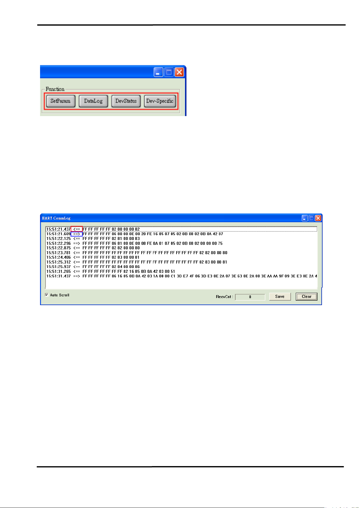
(2) “DataLog” button :
=> It will open the HART communication screen.
<1> <== : HDS receive HART command.
<2> ==> : HDS send(response) HART command.
[1] “Auto Scroll” option :
=> If checked, it will show the latest HART communication data.
[2] “RecvCnt” field :
=> Show the total number of received HART command of HDS not
including the response command.
[3] “Save” button :
=> Save all the HART communication data to file.
[4] “Clear” button :
=> Clear all the HART communication data.
(3) “DevStatus” button : (Supported in v1.02)
The “DevSta Return Mode” option :
=> It is used to set the return mode of HART device status. (All the
simulated HART devices use the same settings)
HDS (HART Device Simulator) User Manual (Ver 1.09, 2020/11/19) ------------- 7
Page 8
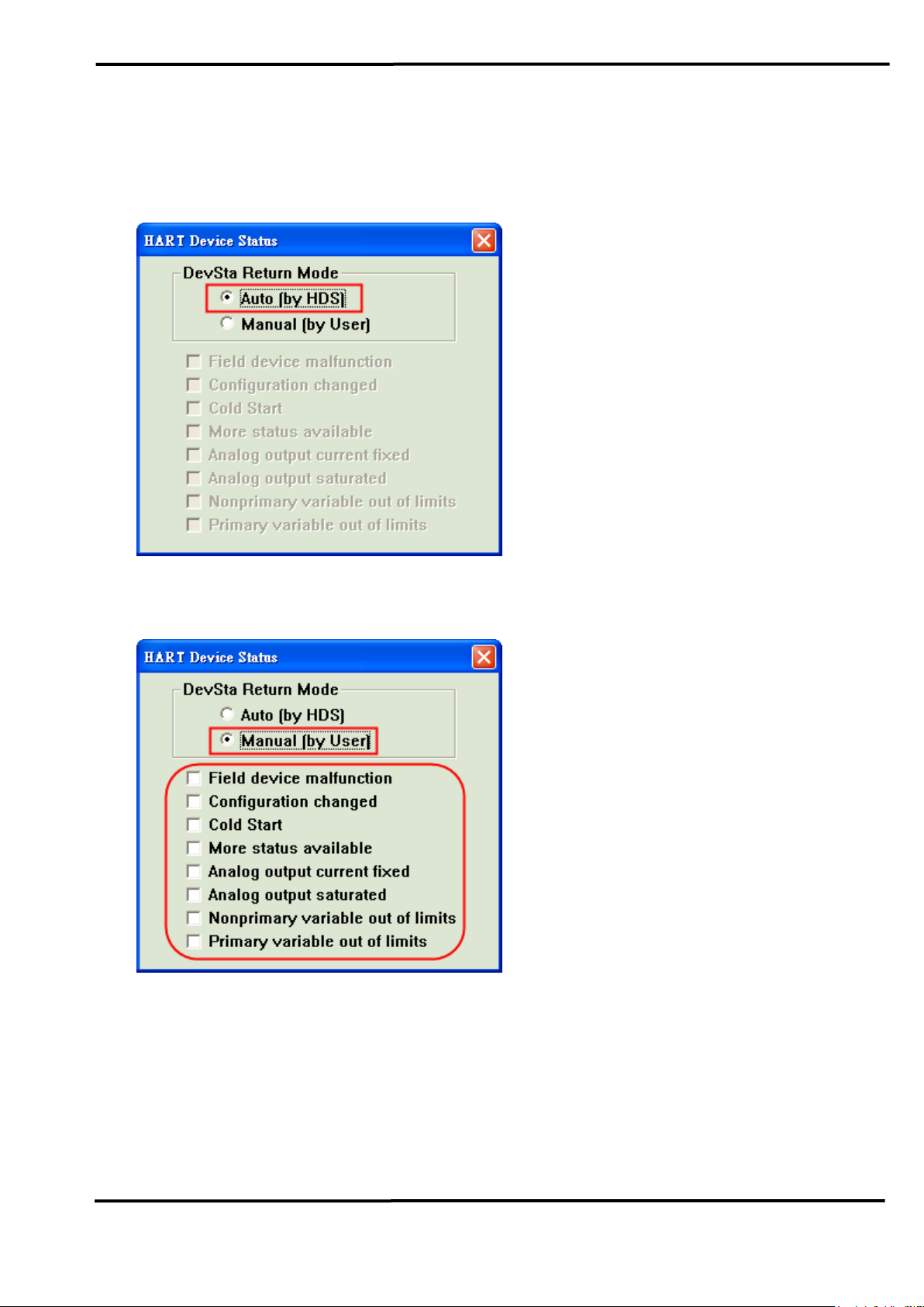
[1] Auto Mode :
The HART device status is decided by HDS software according to the
current HART comm. status.
[2] Manual Mode :
The HART device status is decided by users according to the below
“check” options.
(4) “Dev-Specific” button : (Supported in v1.05.1)
[1] It is used to set the parameters of the device-specific command. (All
the simulated HART devices use the same settings)
[2] It supports 64 parameters for every device-specific command.
[3] It supports device-specific command from 128 ~ 253.
HDS (HART Device Simulator) User Manual (Ver 1.09, 2020/11/19) ------------- 8
Page 9
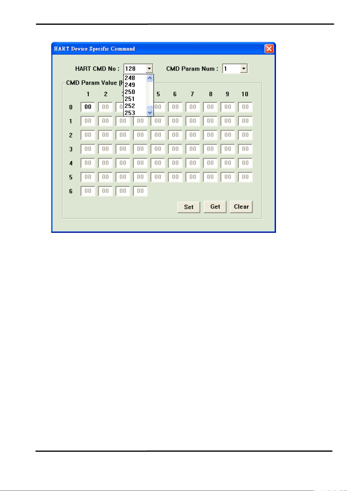
[1] “HART CMD No” option :
=> Choose HART device-specific command no.
[2] “CMD Param Num” field :
=> Choose the amount of parameters for the chosen HART devicespecific command no.
[3] “CMD Param Value (Hex)” field :
=> Set the parameter value with Hexadecimal format.
[4] “Set” button :
=> Save the settings of the screen to the HDS.ini file.
[5] “Get” button :
=> Get the settings from the HDS.ini file and show them to the screen.
[6] “Clear” button :
=> Set all the parameter value to be zero.
HDS (HART Device Simulator) User Manual (Ver 1.09, 2020/11/19) ------------- 9
Page 10
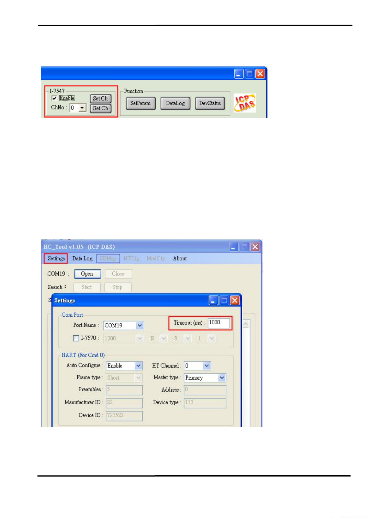
2.1.4 I-7547 Function
(1) “Enable” checkbox :
=> When checked, the HART channel setting of I-7547 will be enabled.
(2) “ChNo” combox :
=> It is used to choose the HART channel no. of I-7547.
(3) “SetCh” button :
=> It is used to set the HART communication channel of I-7547.
(4) “GetCh” button :
=> It is used to get the current HART communication channel of I-7547.
[ Note ]
1. When using I-7547, the timeout value should be more than 1000ms in
the HART master program for stable HART communication.
HDS (HART Device Simulator) User Manual (Ver 1.09, 2020/11/19) ------------- 10
Page 11

2.2 HDS Other Function
2.2.1 HART Supported Command
HDS supports a lot of HART commands as below:
1. Universal command :
00, 01, 02, 03, 07, 08, 09, 11, 12, 13, 14, 15, 16, 17, 18, 19, 20, 21, 22
2. Common-Practice command :
[1] 33 ~ 38
[2] 40 ~ 44
[3] 47 ~ 51
[4] 59, 71, 76, 89, 90, 95, 108, 109
3. Device-Specific command :
128 ~ 253
HDS (HART Device Simulator) User Manual (Ver 1.09, 2020/11/19) ------------- 11
Page 12
3. FAQ
Q01. Run the HDS tool step by step?
A01 : (2015/12/17)
Example
(1) Hardware required:
[1] I-7567 or I-7570 or I-7547 * 1 (as Slave)
[2] I-7567 or I-7570 or I-7547 * 1 (as Master)
[3] PC
(2) Software required:
[1] HDS (for Slave)
[2] HC_Tool (for Master)
(3) Application structure:
(4) Procedure:
[1] Simulate HART Slave Device
<1> Connect 1 ICP DAS HART converter to PC
<2> Run HDS tool
<3> Choose the ComPort number and click the “Open” button
<4> If using I-7547, please do the following 2 steps
i. Use VxComm Utility to create virtual ComPort for I-7547,
detailed instruction refer to Chapter 4.1 of I-7547 manual
ftp://ftp.icpdas.com.tw/pub/cd/fieldbus_cd/hart/converter/i-7547/manual/
ii. After Opened the virtual ComPort, tick Enable box as below
and choose channel number and “Set Ch”
HDS (HART Device Simulator) User Manual (Ver 1.09, 2020/11/19) ------------- 12
Page 13

<5> Check the “Enable” option for device to simulate
<6> Set the value of the “Long Addr” and “PV/SV/TV/QV” fields
<7> Click the “SetParam” button to save the settings
[2] Test with HART Master Program
<1> Connect another ICP DAS HART converter to PC
<2> Run HC_Tool
<3> Choose the ComPort number in “Setting” and click the “Open”
and “Start” button
<4> Search result as below
<4> Choose “HTCfg” to send and receive HART commands (CMD3)
HDS (HART Device Simulator) User Manual (Ver 1.09, 2020/11/19) ------------- 13
Page 14

Q02. How to modify the parameters for HART simulated device?
A02 : (2016/10/03)
(1) Modify the hardware parameters.
[1] Via the “HDS.ini” file.
(HC_Tool) (HDS.ini)
(2) Modify the “Long Frame Address”.
[1] Modify the value in the “Long Addr (HEX)” field of the HDS
software and then click the “SetParam” button.
HDS (HART Device Simulator) User Manual (Ver 1.09, 2020/11/19) ------------- 14
Page 15

(3) Modify the value of “HART CMD12” (Read Message) ?
[1] In HC_Tool (HART Master), send the “HART CMD17” (Write
Message).
(Read Message, HART CMD12)
(Write Message, HART CMD17)
(4) Modify the current value ?
[1] “Point to Point”模式:
HART device address must be 0. The current will vary depending on
the PV value.
[ Ex1 : PV=0.11111 => Current=-11.868970 ]
HDS (HART Device Simulator) User Manual (Ver 1.09, 2020/11/19) ------------- 15
Page 16

[ Ex2 : PV=15.11111 => Current=5.819850 ]
[2] “Multi-Drop”模式:
HART device address should be between 01 and 15. The current will
be fixed to be 4 mA.
[ Ex1 : PV=0.11111 => Current=4.00000 ]
[ Ex2 : PV=16.11111 => Current=4.00000 ]
HDS (HART Device Simulator) User Manual (Ver 1.09, 2020/11/19) ------------- 16
Page 17

HDS (HART Device Simulator) User Manual (Ver 1.09, 2020/11/19) ------------- 17
Page 18

Q03. How to use HDS to virtually transfer Modbus device to
HART device?
A03 : (2018/11/08)
(1) Hardware required:
[1]. HART converter * 1 (I-7567 or I-7570 or I-7547)
<1> work with HDS software => simulate HART Slave device
[2]. Modbus instrument
[3]. PC * 1
<1> Need to write an nModbus program with following functions:
[1] Collect Modbus device data
[2] Keep updating the Modbus device data to HDS.ini file
<2> Execute HDS.exe software
(2) Software required:
[1]. HDS (HART Device Simulator), Download from:
ftp://ftp.icpdas.com/pub/cd/fieldbus_cd/hart/converter/hds/software/
[2]. HC_Tool (converter utility), Download from:
ftp://ftp.icpdas.com.tw/pub/cd/fieldbus_cd/hart/converter/i-7547/software/
[3]. nModbus related information:
<1> introduction / example
http://www.icpdas.com/products/PAC/i-8000/modbus.htm
<2> nModbus_Demo program:
Reads AI data from Modbus device and modify HDS.ini file,
download from:
ftp://ftp.icpdas.com/pub/cd/fieldbus_cd/hart/converter/hds/software/demo/
(3) Application structure and procedures description:
HDS (HART Device Simulator) User Manual (Ver 1.09, 2020/11/19) ------------- 18
Page 19

[1]. Write an nModbus program to read Modbus device data
(Please save the program to the same folder with HDS program)
[2]. nModbus program updating the HDS.ini file with the Modbus
device data simultaneously.
[3]. Use a HART converter with HDS to simulate HART device
(The simulated HART device shares the same data with Modbus
slave as the program keeps updating the HDS.ini file)
[4]. Use another HART converter with HC_Tool to test
(4) Application function test:
[1]. HART Master setup:
<1> HART converter * 1 (I-7567 or I-7570 or I-7547)
<2> work with HC_Tool software => HART Master functions
[2]. nModbus program gets data from Modbus device
[3]. nModbus program updates the Modbus device data to HDS.ini file
[4]. HDS program shows value which same as Modbus device data
[5]. HC_Tool utility reads data from HDS Cmd3 values
HDS (HART Device Simulator) User Manual (Ver 1.09, 2020/11/19) ------------- 19
Page 20

HDS (HART Device Simulator) User Manual (Ver 1.09, 2020/11/19) ------------- 20
Page 21

Q04. How to use HART Device-Specific commands
A04 : (2018/05/15)
HDS_v1.05.1 supports HART Device-Specific command from 128 to
253 and 64 parameters for every HART Device-Specific command.
[ For Example ]
The user wants HDS to response HART device-specific command 128
with 3 parameters and these value are 0x11, 0x22 and 0x33. Please
follow the below steps:
(1) Set the parameter of HART device-specific CMD 128 for HDS.
HDS (HART Device Simulator) User Manual (Ver 1.09, 2020/11/19) ------------- 21
Page 22

[1] Open “HART Device Specific Command” screen.
[2] Choose “128” in the “HART CMD No” option.
[3] Choose “3” in the “CMD Param Num” option.
[4] Type “11”, “22” and “33” in the “CMD Param Value (HEX)” field.
[5] Click “Set” button to save the settings to HDS.ini.
(2) Send HART master command 128.
[ Method 1: Using ICP DAS HART converters with HC_Tool ]
[1] By using ICP DAS HART converters (I-7567, I-7547 or I-7570) with
HC_Tool.
[2] Click “SRMsg” option to open “Send & Receive Msg” screen.
[3] Search the HART device.
[4] Open “HTCfg” screen to send HART command 3.
[5] Then see the sending HART CMD3 format in “SRMsg” screen
[6] Send the HART command 128 with the same long frame address.
[7] In the “Receive Data” field, it will show the HART CMD128
response from HDS with 0x11, 0x22, 0x33 data.
HDS (HART Device Simulator) User Manual (Ver 1.09, 2020/11/19) ------------- 22
Page 23
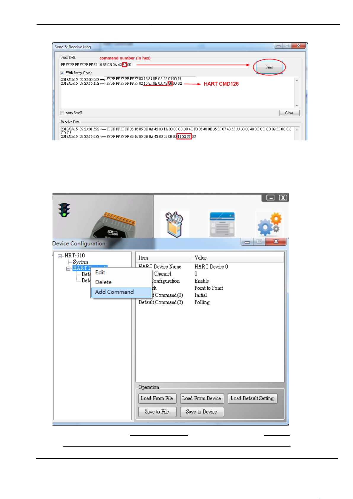
[ Method 2: Using ICP DAS HART gateway with HG_Tool ]
[1] By using ICP DAS HART gateway (HRT-710, HRT-310 or HRT-711)
with HG_Tool.
[2] Run the HG_Tool and connect to the HART gateway.
[3] Add a new command in the “Device Configuration” screen.
[4] Type “128” in the “Command Num” field and “5” in the “In Size” field
(Response Code(2 bytes) + CMD128 Param Number (3 bytes)) and
HDS (HART Device Simulator) User Manual (Ver 1.09, 2020/11/19) ------------- 23
Page 24

“0” in the “Out Size” field.
[5] Click “Save to Device” button.
[6] Using Modbus master tool (ModScan) to get the HART CMD 128
response data from HART gateway.
<1> The response data of HART CMD 128 will be as below.
=> 0x00 0x00 (Response Code) 0x11 0x22 0x33 (Data).
<2> Because the gateway has set the “WORD & BYTE” swap, so
users will see the below data.
HDS (HART Device Simulator) User Manual (Ver 1.09, 2020/11/19) ------------- 24
Page 25

Q05. How to change CMD48 parameters setting
A05 : (2018/07/10)
HDS_v1.05.1 supports HART command 48, all parameters setting stored
in the .ini file of HDS.
[ Example: modify the CMD48 parameter of HART Device00 ]
(1) Open the HDS.ini file
(2) Find [HTDev00_Cmd048], modify parameter value and save (as below)
Send CMD48 to corresponding device, you can see the saved changes
HDS (HART Device Simulator) User Manual (Ver 1.09, 2020/11/19) ------------- 25
Page 26

Q06. How to simulate HART 7.0 device by HDS
A06 : (2019/02/13)
HDS supports simulating HART 7.0 devices after HDS_v1.06, users just
need to do three steps as described below:
1. Tick the “HART v7.0” option to enable “MfrID (v7)” field editing
2. Fill in the correct parameters of HART 7.0 device to the “MfrID (v7)”
and “Long Address” fields in HDS.
3. Click “SetParam” button.
Here is an example of simulating HART 7.0 device:
(1) Below is the information of MP100 HART 7.0 device from 3S Co., Ltd.
(2) Simulate HART 7.0 device with HDS.
[1] Fill in the value of Manufacture ID (hex) – “6084” to the “MfrID (v7)”
field of HDS.
[2] Fill in the value of Device Type ID (hex) – “E28D” and additional
“000000” to the “Long Addr” field of HDS.
HDS (HART Device Simulator) User Manual (Ver 1.09, 2020/11/19) ------------- 26
Page 27

[3] Click “SetParam”:
(3) Test the simulated HART device by using a HART converter (I-7567/ I-
7570/ I-7547) with HC_Tool (after version v1.08).
HC_Tool download :
ftp://ftp.icpdas.com.tw/pub/cd/fieldbus_cd/hart/converter/i-7567/software/
HDS (HART Device Simulator) User Manual (Ver 1.09, 2020/11/19) ------------- 27
Page 28

Q07. How to use Modbus to communicate with HDS ?
A06 : (2019/08/26)
(1) Using ICP DAS HART Converter with HDS to simulate HART
device:
[1] Refer to the steps of FAQ01.
(2) Additional to add ICP DAS Modbus/HART Gateway. So users can
use Modbus to communicate with HDS in the PC or PLC side.:
(Using the method, users don’t need to know HART protocol. Just
using Modbus communication and can access HDS data.)
[1] Adopt HRT-310 or HRT-710 structure : (For MB/RTU)
[2] Adopt HRT-711 structure : (For MB/TCP)
HDS (HART Device Simulator) User Manual (Ver 1.09, 2020/11/19) ------------- 28
Page 29

Q08. How to response HART specific command 158 in HDS ?
A08 : (2020/11/19)
[ The setting steps of HDS ]
(1) Using ICP DAS HART Converter with HDS to simulate HART slave device.
[1] Enable HART Device Address 0 (Long Address : 0xE28D990328) in HDS.
(2) For example, the response value of the specific command 158 in HDS is
103.518 (HEX value will be 0x 42CF0937):
[1] In HDS, click the ”Dev-Specific” button to open the setting screen of
HART device specific command.
<1> HART CMD No. : choose “158”
<2> CMD Param Num : choose “4”
<3> CMD Param Value (HEX) : input 42, CF, 09, 37 in the field 1 to 4.
<4> Click the ”Set” button to save the settings of the specific command 158.
[ The testing steps of HC_Tool ]
(3) Using ICP DAS HART converter with HC_Tool to simulate HART master tool:
[1] Click the ”Start” button to search all HART device automatically and it will
show HART devices found in the “Information” field.
HDS (HART Device Simulator) User Manual (Ver 1.09, 2020/11/19) ------------- 29
Page 30

(4) Using the ”Specific CMD” function of HC_Tool to get the value of the specific
command 158 in HDS.
[1] In HC_Tool, click the ”HTCfg” item to open the screen of ”HART Command”.
[2] In the screen of ”HART Command” :
<1> DevAddr : choose the HART device
<2> click the ”Specific” page
<3> Specific Cmd : choose “158”
HDS (HART Device Simulator) User Manual (Ver 1.09, 2020/11/19) ------------- 30
Page 31
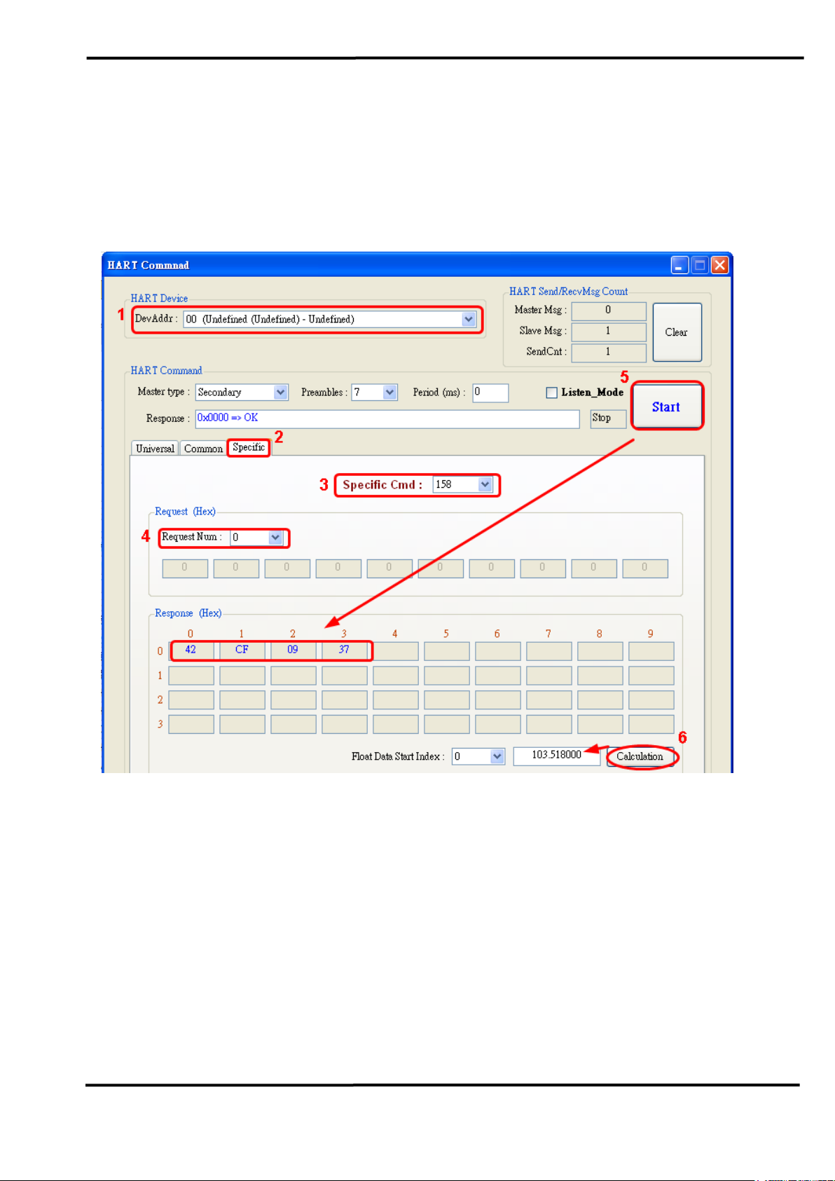
<4> Request Num : choose “0” (different according to each HART device)
<5> click the ”Start” button to get the value of the specific command 158 of
HDS and shown in the Response (Hex) field. (42 CF 09 37 is the same
with the value in HDS)
<6> click the ”Calculation” button and the assigned HEX value will be
converted to the float value. (103.518 is the same with the value in HDS)
Q09. How to simulate the abnormal status of HDS ?
A09 : (2020/11/19)
[ The setting steps of HDS ]
(1) Using ICP DAS HART converter with HDS to simulate HART slave device.
HDS (HART Device Simulator) User Manual (Ver 1.09, 2020/11/19) ------------- 31
Page 32

(2) In HDS, click the ”DevStatus” button to open the screen of “HART Device
Status”.
[1] Click the ”Manual (by User)” option to enable the setting parameters of
“ HART Device Status”.
[2] For example, check the below three abnormal status for the current
HART device status in HDS.
[ The testing steps of HC_Tool ]
(3) Using ICP DAS HART converter with HC_Tool to simulate HART master tool:
[1] Click the ”Start” button to search all HART device automatically and it will
show HART devices found in the “Information” field.
[2] Click the ”HTCfg” item to open the screen of ”HART Command”.
HDS (HART Device Simulator) User Manual (Ver 1.09, 2020/11/19) ------------- 32
Page 33

(4) Using HART CMD3 of HC_Tool to get the current HART device status.
[1] Click the ”Universal” item.
[2] Click the “Cmd3” item.
[3] Click the ”Start” button to send HART CMD3 and it will get the command result
(status and value). In the “Response” field, the command status is “Cold Start”,
“Config_Changed”, “Device Malfunction” and it is the same with the abnormal
settings in HDS.
HDS (HART Device Simulator) User Manual (Ver 1.09, 2020/11/19) ------------- 33
Page 34

Q10. How to enable/disable the burst mode of HDS ?
A10 : (2020/11/19)
(1) According to HART spec., HART command 109 is used to control the burst
mode of HART device to be enabled or disabled. The HDS software also
adopts the same method.
[ The testing steps of HC_Tool ]
(2) Using ICP DAS HART converter with HC_Tool to simulate HART master tool.
[1] Click the ”Start” button to search all HART device automatically and it will
show HART devices found in the “Information” field.
[2] Click the ”HTCfg” item to open the screen of ”HART Command”.
(3) Send HART command 109 to enable/disable the burst mode of HDS:
[1] Click the ”Common” item
[2] Common-Practice Cmd: choose ”109: Burst Mode Control”
HDS (HART Device Simulator) User Manual (Ver 1.09, 2020/11/19) ------------- 34
Page 35

[3] Burst Mode: choose ”1: Enable“
[4] Click the ”Start” button to send HART command 109 to enable the burst
mode of HDS.
(In Data Log, the burst mode of HDS enabled)
[5] Burst Mode: choose ”0: Disable“
[6] Click the ”Start” button to send HART command 109 to disable the burst
mode of HDS.
Q11. How to set HART burst command number of HDS ?
A11: (2020/11/19)
(1) According to HART spec., HART command 108 is used to set HART burst
HDS (HART Device Simulator) User Manual (Ver 1.09, 2020/11/19) ------------- 35
Page 36

command number. The HDS software also adopts the same method.
[ The testing steps of HC_Tool ]
(2) Using ICP DAS HART converter with HC_Tool to simulate HART master tool.
[1] Click the ”Start” button to search all HART device automatically and it will
show HART devices found in the “Information” field.
[2] Click the ”HTCfg” item to open the screen of ”HART Command”.
(3) Send HART command 108 to set HART burst command number of HDS:
[1] Click the ”Common” item
[2] Common-Practice Cmd: choose ”108: Write Burst Mode Command
Number”
[3] Burst Mode CmdNo.: choose ”HART Cmd1“
[4] Click the ”Start” button to send HART command 108 to set HART burst
command number to be HART command 1.
HDS (HART Device Simulator) User Manual (Ver 1.09, 2020/11/19) ------------- 36
Page 37

(In Data Log, HART burst command number is changed to HART command 1)
HDS (HART Device Simulator) User Manual (Ver 1.09, 2020/11/19) ------------- 37
Page 38

Ver.
Author
Date
Description
1.00
Edward
2015/12/17
1. First version.
1.01
Edward
2016/07/28
1. Add the “DevStatus” button to set the status of
the simulated HART device.
1.02
Edward
2016/11/10
1. Add the Q02 in FAQ.
2. Add the section 2.1.4 (I-7547 Function)
1.03
Peter
2017/06/30
1. Add the Q03 in FAQ
1.04
Peter
2018/05/15
1. Add the Q04 in FAQ
2. HDS_1.05.1 version new function:
[1] New supported command (48, 128~253)
1.05
Peter
2018/11/01
1. Add the Q05 in FAQ
1.06
Peter
2018/11/30
1. Modify Q01 and Q03 in FAQ
1.07
Peter
2019/02/13
1. HDS_1.06 new function:
(1) Support HART v7.0 protocol. (partial)
(2) New supported command (8)
2. Section 2.1.2 add description of new functions
3. Add the Q06 in FAQ
1.08
Edward
2020/03/20
1. Add the Q07 in FAQ
2. HDS_1.07 new function:
(1) New supported CMD (9, 11, 20~22, 33, 43,
44, 47, 50, 51, 71, 76, 89, 90, 95)
1.09
Edward
2020/11/19
1. Add the Q08~Q11 in FAQ.
4. Version History
HDS (HART Device Simulator) User Manual (Ver 1.09, 2020/11/19) ------------- 38
 Loading...