

GW-5492/GW-5493
User’s Manual v1.0
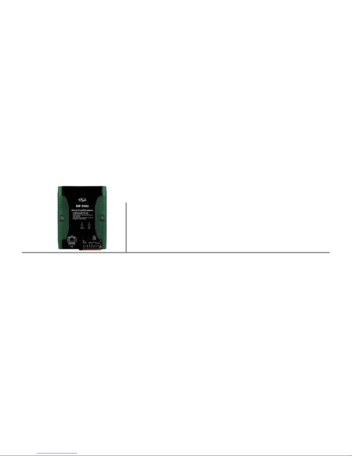
ICP DAS BACnet to Modbus Gateway

GW-5492/GW-5493 User’s Manual
V1.01 2011/09/01
2
Version
Author
Date
Description of Changes
1.01
Eugene
2012/03/20
First Released Revisi on
Warranty
All products manuf ac tured by ICP DAS are under warranty regarding def ectiv e m aterials for a period of
one year from the date of delivery to the original purchaser.
Warning
ICP DAS assumes no liabili ty for damages resulting from the use of this product. ICP DAS reserves the
right to change this manual at any time without notice. The i nformation furnished by ICP DAS is
believed to be accurate and reli able. However, no responsibilit y i s assumed by I CP DAS for its use, or
for any infringements of patents or other rights of thir d parties resulting from its use.
Copyright
All rights are reserved by ICP DAS Co., Ltd. 2012.
Trademark
The names used for identif ic ation only may be registered tradem arks of their respective compani es.
Document Revision

GW-5492/GW-5493 User’s Manual
V1.01 2011/09/01
3
Table of Contents
1. General Information ................................................................................................................ 4
1.1 BACnet Introduct ion ............................................................................................... 4
1.2 About GW-5492 ..................................................................................................... 4
1.3 About GW-5493 ..................................................................................................... 4
1.4 Hardware Specifi c ation .......................................................................................... 4
2. Hardware................................................................................................................................ 6
2.1 Pin Assignment ...................................................................................................... 6
2.2 LED Indicati on ....................................................................................................... 7
2.2.1 Power LED ....................................................................................................... 7
2.2.2 Module Status indicator LED............................................................................. 7
3. Web Based Configuration Tool ............................................................................................... 8
3.1 Overview ............................................................................................................... 8
3.2 Device Selection .................................................................................................... 8
3.3 Using Web-based Configuration Tool ..................................................................... 8
3.4 Tab menu of Configuration Tool ........................................................................... 11
3.4.1 System ........................................................................................................... 11
3.4.2 Modbus .......................................................................................................... 11
3.4.3 BACnet........................................................................................................... 11
3.4.4 Modbus/BACnet Mappi ng ............................................................................... 11
3.5 System tab .......................................................................................................... 12
3.5.1 System Process ............................................................................................. 13
3.5.2 Network Setti ngs ............................................................................................ 13
3.5.3 Serial Port Settings ......................................................................................... 13
3.5.4 Import/Export/Updating Firmware ................................................................... 14
3.5.5 Change User Name & Passsword ................................................................... 14
3.6 Modbus tab ......................................................................................................... 15
3.6.1 Devices addition ............................................................................................. 15
3.6.2 Devices list ..................................................................................................... 17
3.7 BACnet tab .......................................................................................................... 19
3.7.1 BACnet basic information configuration........................................................... 19
3.7.2 BACnet Object Types and instance settings.................................................... 20
3.8 Modbus/BACnet Mappi ng tab .............................................................................. 21

GW-5492/GW-5493 User’s Manual
V1.01 2011/09/01
4
GW-5492
GW-5493
System
CPU
32-bit
SDRAM
64 MB
Flash
64 MB
COM1
RS-232 (RxD, TxD, GND); Non-isolation
isolated
Ethernet
10/100Base-TX Ethernet Cont r oller
Protocol
Modbus
Modbus RTU Master
Modbus TCP Master
BACnet
BACnet/IP Slave
BACnet Object s
AI, AO, AV, BI, BO, BV, MSI, MSO, MSV (Maximum: 200 each)
1. General Infor m a ti on
1.1 BACnet Introduction
BACnet (Buil ding Automation and Control Networki ng) protocol has been designed specifi cally to
meet the communication needs of building automation and control systems for applications such as
heating, v entil ating, ai r-conditioni ng control…etc. The GW-549x gateways contains a large num ber of
BACnet objects (AI, AO, AV, BI, BO, BV, MSI, MSO, MSV) gives you flexibility in mapping Modbus RTU
registers to any combination of BACnet objects. Multiple BIBBs (DS-RP-B, DS-RPM-B, DS-WP-B,
DS-WPM, DS-COV-B…etc.) are supported. All t he data transfer is configurabl e using a standard Web
browser.
1.2 About GW-5492
GW-5492 is a fully configurable universal Modbus RTU to BACnet/IP gateway. The GW-5492
includes BACnet/IP Server and Modbus RTU Master which is used to make Modbus RTU devices
accessible on a BACnet network.
1.3 About GW-5493
GW-5493 is a fully configurable universal Modbus RTU to BACnet/IP gateway. The GW-5493
includes BACnet/IP Server and Modbus TCP Client which is used to make Modbus TCP devices
accessible on a BACnet network.
1.4 Hardware Specification
COM2 RS-485 (D+, D-)2500 VDC;
Not use

GW-5492/GW-5493 User’s Manual
V1.01 2011/09/01
5
DM-RD-B
Environmental
Dimensions (W x L x H)
91mm x132mm x 52mm
Operating Temp.
-25 ~ +75 °C
Storage Temp.
-30 ~ +85 °C
Humidity
5_90% PH, non-condesing
Power Input Range
+10V to +30+10V to +30VDC
Power Consumption
4.8W (0.2A @ 24VDC)
BIBB DS-RP-B, DS-RPM-B, DS-WP-B, DS-WPM-B, DS-COV-B,
DM-DDB-B, DM-DOB-B, DM-DCC-B, DM-TS-B, DM-UTC-B,

GW-5492/GW-5493 User’s Manual
V1.01 2011/09/01
6
Pin
Name
Description
1
F.G.
Firm Ground
2
GND
Ground of power supply
3
+VS
V+ of power supply (+10V t o +30VDC unregulated)
4
TxD
TxD of COM3 (RS-232)
5
RxD
RxD of COM3 (RS-232)
6
Data+
Data+ of COM2 (RS-485)
7
Data-
Data- of COM2 (RS-485)
8
GND
Ground of COM1 (RS-232)
9
TxD
TxD of COM1 (RS-232)
10
RxD
RxD of COM1 (RS-232)
2. Hardware
2.1 Pin Assig nme nt

GW-5492/GW-5493 User’s Manual
V1.01 2011/09/01
7
2.2 LED Indication
GW-5492/GW5493 provides two LEDs to indicate what situation is in the GW-5492/GW-5493.
They are described as follows.
2.2.1 Power LED
The GW-5492/GW-5493 needs +10 ~ +30 VDC power input and consumes 4.8W. The Power LED
will be turn on after applyi ng power and i t will be flashing two tim es per second.
2.2.2 Module Status indicator LED
The LED indicates the communication status of the GW-5492/GW-5493. The following
description shoes the conditions of error status.
Green light flashes: BACnet Client is communicating with GW-5492/GW-5493
Red light flashes: Time out error on Modbus end

GW-5492/GW-5493 User’s Manual
V1.01 2011/09/01
8
3. Web Based Configuration Tool
This chapter is to descri be the web structure, sof tware operating interf aces, and configuration of
BACnet and Modbus mapping.
GW-5492/GW-5493 provides Web-based confi guration for the BACnet and Modbus setti ngs. The
functions i ncl ude:
System informati on and configuration
Network and COMPort settings
Management and settings of Device’s Points (Address) for Modbus RTU Master and TCP
Client
BACnet configuration and management
BACnet Instance and Modbus Device point Mapping management
3.1 Overview
This document is to describe the web structur e, software operat ing interfaces, and configuration of
BACnet and Modbus mapping.
GW-5492/GW-5493 provides Web-based confi guration f or the BACnet and Modbus settings. T he
functions i ncl ude:
System information and configurati on
Network and COM Port settings
Management and settings of Device’s Points (Address) for Modbus RTU Master and TCP
Client
BACnet configuration and management
BACnet Instance and Modbus Device point Mapping management
3.2 Device Selection
GW-5492: BACnet /I P (Server) to Modbus RTU (Client) Gateway
GW-5493: BACnet /I P (Server) to Modbus TCP (Client) Gateway
3.3 Using Web-based Configu r a ti on Tool
Connect the GW-549x to network, and use standard web browser (Internet Explorer, Mozilla Firefox)
to launch the user int erface. The default link and network setti ngs are as followed:
Web Address:
http://192.168.255.1
 Loading...