

Page 1

Version: 1.0/ Updated: Jun. 2020
GW-2200
Firmware Update via Ethernet
Website: http://www.icpdas.com
Ch. 2. Firmware Update Procedure
Ch. 3. Troubleshooting
Ch. 4. Additional Information
Ch.1. Setting up the GW-2200 Series
SUPPORT
Models supported include GW-2212i, GW-2222i,
GW-2232i, GW-2215i, GW-2225i, GW-2235i
WARRANTY
All products manufactured by ICP DAS are warranted
against defective materials for a period of one year from
the date of delivery to the original purchaser.
WARNING
ICP DAS assumes no liability for damages consequent to
the use of this product. ICP DAS reserves the right to
change this manual at any time without notice. The
information furnished by ICP DAS is believed to be
accurate and reliable. However, no responsibility is
Series
assumed by ICP DAS for its use, nor for any infringements
of patents or other rights of third parties resulting from its
use.
COPYRIGHT
Copyright © 2020 by ICP DAS. All rights are reserved.
TRADEMARKS
Names are used for identification purposes only and may
be registered trademarks of their respective companies.
CONTACT US
If you have any questions, please feel free to contact us.
We will respond within 2 working days.
Email: service@icpdas.com
ICP DAS CO., LTD.
Page 2
1. Setting up the GW-2200 Series
Before updating the firmware, please ensure that the network settings for both your host computer and any
GW-2200 series modules are correctly configured, or the update procedures via the Ethernet network may
not function correctly.
Step 1: Connect the GW-2200 series to the same hub or the same sub-network as your Host
PC, and attach a power supply to the GW-2200 series. Do not connect the GW-2200 series
to a router or directly to the Internet as this may cause the update process to fail.
Please refer to “Chapter 3-Connecting the Power and Host PC” in the GW-2200 Quick Start Guide for more
detailed information.
Download the Quick Start Guide.
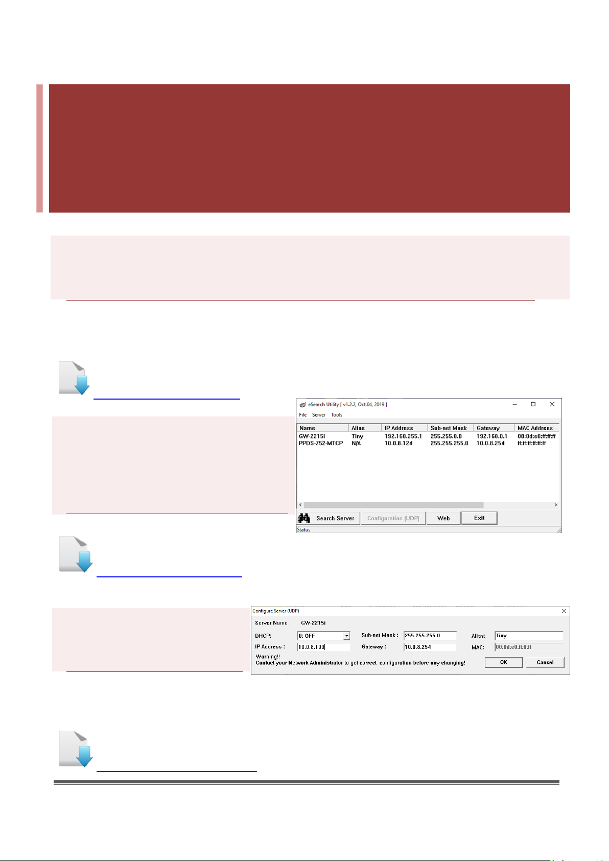
Step 2: Install the eSearch Utility on your
Host PC, and then run the Utility to search
for any GW-2200 series modules
connected to the network.
Download the eSearch Utility.
Step 3: Configure the correct
network settings for the required
GW-2200 series module.
Please refer to “Chapter 4-Configuring Ethernet Settings” in the GW-2200 Quick Start Guide. If the IP address
settings do not work correctly, please refer to note1 (Page 18).
Download the Quick Start Guide.
GW-2200 Series Firmware Update via Ethernet (Ver. 1.0/Mar. 2020) Page: 1
Page 3

2 3 1
2. Firmware Update Procedure
The firmware update can fail when the computer has multiple network interfaces (e.g., LAN and Wi-Fi).
Therefore, enable only one network interface for updating the firmware, and temporarily turn off other
network interfaces, firewalls, and anti-virus software first.
2.1 GW-2200 Firmware Update
Two methods can be used to update the firmware: “Local Firmware Update” (traditional) and
“Remote Firmware Update” (TeamViewer). The Local Firmware Update method requires the user to
manually adjust the position of the Init/Run Switch and reboot the module in order to initialize the
firmware update. Refer to Section 2.1.1 “Local Firmware Update” for more details. The Remote
Firmware Update method allows the user to initialize the module via a web interface without
needing to adjust the hardware switch. Initialization via the web interface is useful when the module
is installed at a remote site and can be accessed via the TeamViewer application installed on a
remote PC. Refer to Section 2.1.2 “Remote Firmware Update” for more details.
2.1.1 Local Firmware Update
Step 1: In the eSearch Utility, click the “Search Servers” button to search the for any GW-2200
modules connected to the network . (The network settings of the GW-2200 module as described
in Step 3 on Page1)
Step 2: Right click on the name of
the GW-2200 module to be updated.
Step 3: Select the “Firmware Update”
item from the popup menu and the
“Open” dialog box will be displayed.
GW-2200 Series Firmware Update via Ethernet (Ver. 1.0/Mar. 2020) Page: 2
Page 4
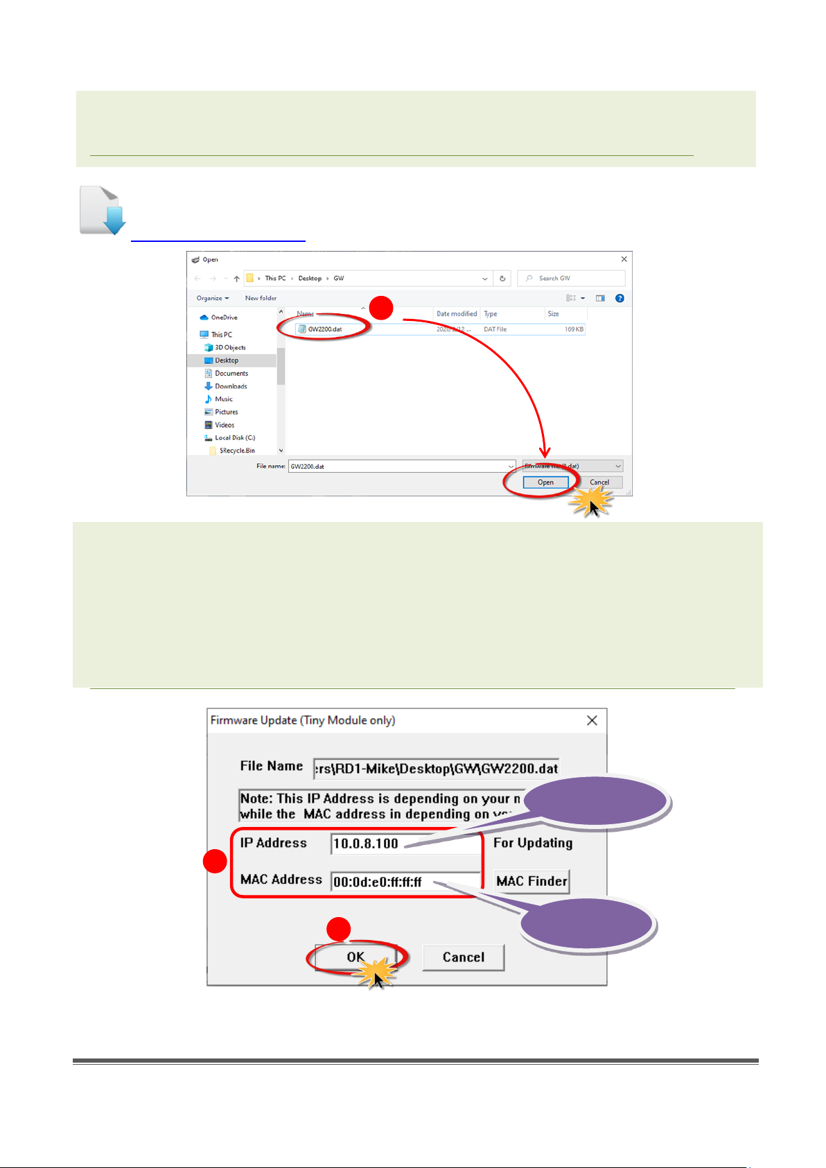
Step 4: In the “Open” dialog box, select the firmware file (GW2200.dat) that will be
4
5
6
Factory-default
MAC Address
Valid IP Address
used to update the module and then click the “Open” button.
Download the Firmware File.
Step 5: Assign a valid IP Address (can be different with the current IP) and the
factory-default MAC Address for the GW-2200 module. If this IP address is invalid (e.g. IP
Address: 0.0.0.0) or a user-defined MAC address is assigned. Refer to note 2 (Page 18) and
note 3 (Page 19) for more details.
Step 6: Click the “OK” button.
GW-2200 Series Firmware Update via Ethernet (Ver. 1.0/Mar. 2020) Page: 3
Page 5
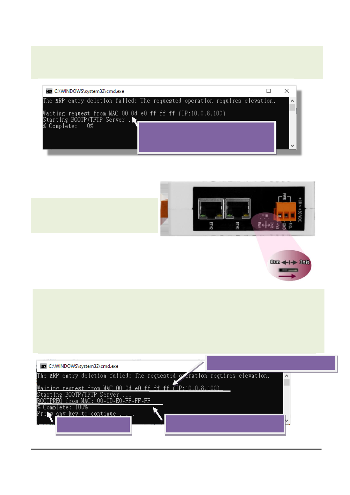
Waiting for a request from the GW-2200
Firmware update begins
Request received from this MAC Address
Waiting for a request from this MAC Address
Step 7: You are now ready to update the firmware. A Command Prompt windows will
be displayed the progress of the update.
module to begin updating the device
Step 8: Set the “Init Switch” on the
GW-2200 module to the “Init” position.
Step 9: Power-on reset the GW-2200 module in “Init Mode” to initiate the update.
Step 10: Confirm that the two MAC addresses (factory-default) listed in the Command Prompt
window, “Waiting request from MAC x.x.x.x” and “BOOTPREQ from MAC: x.x.x.x”, are the
same, as indicated in the image below. If these addresses do not match, the update cannot
proceed. Refer to note4 (Page 19) below for more details.
GW-2200 Series Firmware Update via Ethernet (Ver. 1.0/Mar. 2020) Page: 4
Page 6
13
14
15
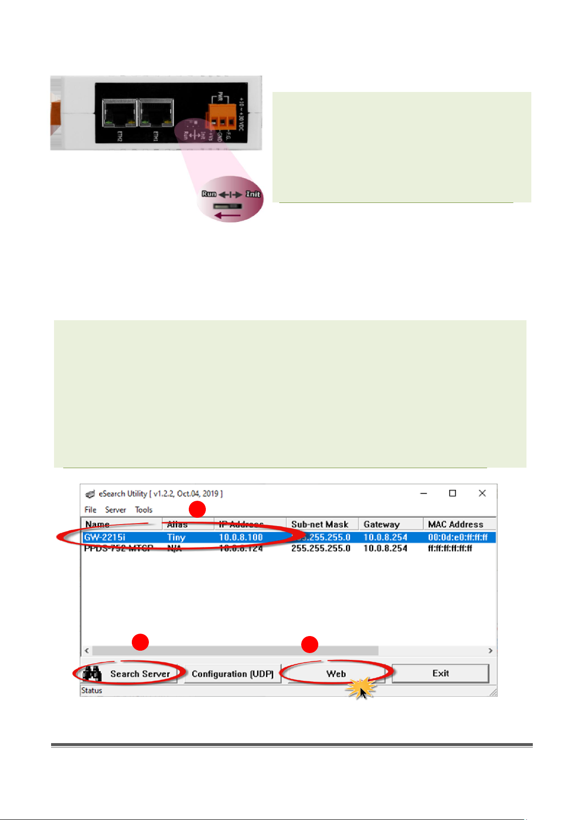
Step 11: Once the update is complete (i.e.,
when the progess indicator reaches 100%), set
the “Init Switch” to the “Run” position.
Step 12: Power-on reset the GW-2200 module
to operate the module in “Run Mode”.
Step 13: In the eSearch Utility, search for the GW-2200 module again to verify that it is
functioning correctly. Note that the network settings for the module may need to be
reconfigured after updating the firmware. Refer to Step 3 in Chapter 1 above for more
details.
Step 14: Click the name of the GW-2200 module to highlight it.
Step 15: Click the “Web” button and the default web browser will be opened.
GW-2200 Series Firmware Update via Ethernet (Ver. 1.0/Mar. 2020) Page: 5
Page 7

16
17
Step 16: Log in to the web configuration pages for the GW-2200 (use the default password
“admin”).
Step 17: Verify that the firmware version and date details are correct.
GW-2200 Series Firmware Update via Ethernet (Ver. 1.0/Mar. 2020) Page: 6
Page 8

2.1.2 Remote Firmware Update
eSearch Utility is
User is there
remotely controlling
the firmware update
procedures.
1 2 3
In order to perform a Remote Firmware Update, use an application that allows an external system to
be remotely controlled, such as TeamViewer, to create a connection between the local and the
remote system. Note that all firmware update procedures need to be carried out on the remote
system.
running on the
computer to update
module's firmware.
Follow the procedure described below to update firmware of the GW-2200 on the remote PC:
Step 1: In the eSearch Utility, click the “Search Servers” button to search for any GW-2200
modules connected to the network . (The network settings the GW-2200 module are described
in Step 3 of Chapter1)
Step 2: Right click the name of the
GW-2200 module to be updated.
Step 3: Select the “Firmware Update”
item from the popup menu and the
“Open” dialog box will be displayed.
GW-2200 Series Firmware Update via Ethernet (Ver. 1.0/Mar. 2020) Page: 7
Page 9

Step 4: In the “Open” dialog box, select the firmware file (GW2200.dat) that will be
4
5
6
Factory-default
MAC Address
Valid IP Address
used to update the module and then click the “Open” button.
Download the Firmware File.
Step 5: Assign a valid IP Address (can be different with the current IP) and the
factory-default MAC Address for the GW-2200 module. If this IP address is invalid (e.g. IP
Address: 0.0.0.0) or a user-defined MAC address is assigned. Refer to note 2 (Page 18) and
note 3 (Page 19) for more details.
Step 6: Click the “OK” button.
GW-2200 Series Firmware Update via Ethernet (Ver. 1.0/Mar. 2020) Page: 8
Page 10

Waiting for a request from the GW-2200
8
Step 7: You are now ready to update the firmware. A Command Prompt windows will
be displayed the progress of the update.
module to begin updating the device
Step 8: Open a web browser such as Internet Explorer or Firefox and enter the URL for
the GW-2200 in the address bar of the browser and log in to the web configuration
pages (use the default password “admin”).
GW-2200 Series Firmware Update via Ethernet (Ver. 1.0/Mar. 2020) Page: 9
Page 11

Firmware update begins
Request received from this MAC Address
Waiting for a request from this MAC Address
9
10
Step 9: Click the “Network Setting” tab to display the Network Settings page.
Step 10: Click the “Update”
button in the “Remote
Firmware Update” section
to start the update.
Step 11: Confirm that the two MAC addresses (factory-default) listed in the Command Prompt
window, “Waiting request from MAC x.x.x.x” and “BOOTPREQ from MAC: x.x.x.x”, are the
same, as indicated in the image below. If these addresses do not match, the update cannot
proceed. Refer to note4 (Page 19) below for more details.
Step 12: Once the update is complete (i.e., when the progess indicator reaches 100%), close
the Command Prompt window.
Note: If the Remote Firmware Update method fails, please refer to Section 3.1 Firmware update in
BOOT mode (local operation) to restore the module.
GW-2200 Series Firmware Update via Ethernet (Ver. 1.0/Mar. 2020) Page: 10
Page 12

Step 13: In the eSearch Utility, search for the GW-2200 module again to verify that it is
16
17
14
15
13
functioning correctly. Note that the network settings for the module may need to be
reconfigured after updating the firmware. Refer to Step 3 in Chpater1 above for more
details.
Step 14: Click the name of
the GW-2200 module to
highlight it.
Step 15: Click the “Web”
button and the default
web browser will be
opened.
Step 16: Log in to the web configuration pages for the GW-2200 (use the default password
“admin”).
Step 17: Verify that the version and date details for the firmware are correct.
GW-2200 Series Firmware Update via Ethernet (Ver. 1.0/Mar. 2020) Page: 11
Page 13

3. Troubleshooting
3.1 Firmware update in BOOTP mode
If the module is not functioning correctly (e.g. there is no response to the search request, or if the
system LED is always displayed as either off or on), please download a new image of
the firmware from the ICPDAS web site and then update the firmware for the module using
the following procedure.
Step 1: In the eSearch Utility, select the “BOOTP”
item from the “Server” menu. A check mark
should be displayed next to the item after it has
been selected.
Step 2: Set the “Init Switch” to the “Init Mode”
position.
Step 3: Power-on and reboot the GW-2200 series
module and then click the “Search Servers” button to
search for the GW-2200 series at the same time. Note,
the module sends BOOTP messages about 5 seconds
when booting in Init Mode. If this step is not successful,
reboot the module and execute the search again.
GW-2200 Series Firmware Update via Ethernet (Ver. 1.0/Mar. 2020) Page: 12
Page 14

Step 4: Right click on the name “BOOTP” and then select the “Firmware Update” item from the
popup menu.
Step 5: Refer to Steps 4 to 17 in “Chapter 2-Firmware Update Procedure” to complete the update
process. Note, the module will response with no IP address in the BOOTP mode. User has to assign
a valid IP manually in step 5 of page 3.
Step 6: After updating the firmware, disable BOOTP mode from the eSearch utility. By selecting
“BOOTP” item from the “Server” menu.
GW-2200 Series Firmware Update via Ethernet (Ver. 1.0/Mar. 2020) Page: 13
Page 15

3.2 How to update Firmware when the Different
1
2
3
Network Segment for IP Address of the GW-2200 and
Host PC.
For example, the first time to get the GW-2200 series module, the factory default IP address is
192.168.255.1, but the host PC IP address is 10.0.8.31, refer to the following two methods to update
firmware.
Method 1: Using “Dynamic Host Configuration Protocol (DHCP)” to automatically assigns an IP
address to GW-2200 series module. Follow the procedure described below:
Step 1: Run the eSearch Utility to search for any GW-2200 series modules to the network
Step 2: Double click the name of GW-2200 series to open the “Configure Server (UDP)” dialog box.
Step 3: Select the “1: ON” option from the “DHCP:” drop-down menu and click the “OK” button.
GW-2200 Series Firmware Update via Ethernet (Ver. 1.0/Mar. 2020) Page: 14
Page 16

4
Step 4: Wait 2 seconds and then click the “Search Servers” button again to ensure the GW-2200
series is working well with new configuration.
Step 5: Refer to “Chapter 2-Firmware Update Procedure” for details of how to complete the
update process.
GW-2200 Series Firmware Update via Ethernet (Ver. 1.0/Mar. 2020) Page: 15
Page 17

1
2
3
4
Method 2: Using “Manual configuration” to assigns an IP address to GW-2200 series module. Follow
the procedure described below:
Step 1: Run the eSearch Utility to search for any GW-2200 series modules to the network
Step 2: Double click the name of GW-2200 series to open the “Configure Server (UDP)” dialog box.
Step 3: Select the “0: OFF” option from the “DHCP:” drop-down menu.
Step 4: Contact your Network Administrator to obtain a correct network configuration (such as IP
Address/Sub-net Mask/Gateway). Enter the network settings and click the “OK” button.
GW-2200 Series Firmware Update via Ethernet (Ver. 1.0/Mar. 2020) Page: 16
Page 18

5
Step 5: Wait 2 seconds and then click the “Search Servers” button again to ensure the GW-2200
series is working well with new configuration.
Step 6: Refer to “Chapter 2-Firmware Update Procedure” for details of how to complete the
update process.
GW-2200 Series Firmware Update via Ethernet (Ver. 1.0/Mar. 2020) Page: 17
Page 19

Mode
Flash Protection
Firmware Update
Configuration
Init
No
Yes
Factory-default
Run
Yes
No
User-defined
4. Additional Information
The code contained in the boot loader, which is used to update the firmware image, is not part of
the firmware it-self. This means that, the firmware can still be updated even if the built-in
firmware has been corrupted or does not exist. If the firmware update fails, simply execute the
update procedures again in BOOTP mode, as described in Chapter 3, and the update should be
successful.
The GW-2200 series obtains the IP address assigned by the user and retrieves the firmware image
through the utility program. Note that when updating the firmware, the GW-2200 series uses the
factory-default MAC address rather than any user-defined MAC addresses. The GW-2200 series has
a built-in flash protection feature that prevents any modification to the firmware stored in the flash
memory, before attempting to update the firmware, the “Init Switch” should be set to the “Init”
position and then the GW-2200 series can be powered-on and rebooted to disable the flash
protection. Since the flash memory
then becomes writable, the firmware
can be updated via the Ethernet
network.
Notes:
Note 1: If the IP address settings do not work correctly (e.g. there is no response to a ping
command), please contact your network administrator to obtain a valid IP address for the GW-2200
series module. ………………………………………………………………………………………………. back
Note 2: If the settings displayed in the IP address field of the firmware update window is incorrect
or invalid (e.g. IP address: 0.0.0.0), then a valid IP address must be manually specified for the
GW-2200 series in order to process the update operation. Please contact your network
administrator to obtain a valid IP address before proceeding.
………………………………………………………………………………………………………………………… back
GW-2200 Series Firmware Update via Ethernet (Ver. 1.0/Mar. 2020) Page: 18
Page 20

Note 3: When updating the firmware, the factory-default MAC address is used rather than the
TFTP
BOOTP
Receives the new firmware image
Establishes a connection
Applies this IP address
Broadcasts its MAC address
(Note: Some routers can block
packets)
GW-2200 Seies
Begins the firmware update process
Accepts the connection
Assigns the IP address to the GW-2200
Series
Checks whether the received MAC
address is the same as the
user-assigned MAC address
eSearch Utility
user-defined MAC address. Thus, the MAC address (user-defined) displayed in the firmware update
window may not be the one required. If this is the case, the factory-default MAC address should be
manually entered into the MAC Address field, or restore the MAC address to the factory-default
settings via the web configuration pages.
………………………………………………………………………………………………………………………………… back
Note 4: The “BOOTPREQ from MAC: xx-xx-xx-xx-xx-xx” message indicates there is a module with
the factory-default MAC address “xx-xx…” that is asking for the firmware to be updated. The update
process will not begin if you assign a user-defined MAC address in the firmware update window,
since the addresses do not match. If this situation occurs, repeat the update procedure and
manually enter the factory-default MAC address in the firmware update window, as described in
Step 5 on Page 4. The firmware update procedure is illustrated in the figure below.
………………………………………………………………………………………………………………………………… back
Note 5: BOOTP (Bootstrap Protocol) is defined in RFC-951 and uses UDP ports 67 and 68.
Note6: TFTP (Trivial File Transfer Protocol) is defined in RFC-1350 and
uses UDP port 69.
GW-2200 Series Firmware Update via Ethernet (Ver. 1.0/Mar. 2020) Page: 19
 Loading...