

The following items are included in the package:
GW-2200 Module x 1
Quick Start x1
GW Series Product webpage:
https://www.icpdas.com/en/product/guide+Industrial__Communication+Gateway+tG
W__Modbus__Gateway#1183
Document & Firmware:
https://www.icpdas.com/en/download/index.php?nation=US&kind1=&model=&kw=G
W-2200
NS-205/NS-205PSE/M-7000 Product webpage (optional):
https://www.icpdas.com/en/product/guide+Industrial__Communication+Ethernet__C
ommunication+Ethernet__Switch
https://www.icpdas.com/en/product/guide+Remote__I_O__Module__and__Unit+RS485__I_O__Modules+I-7000#467
GW-2200 Series Quick Start
What’s in the box?
IPv6 version 1.0, Dec. 2020
Related Information
Technical support: service@icpdas.com P1
Hub/Switch(NS-205)
Uses Non-PoE
Switch
Host PC
Power Supply
(+12~+48VDC)
Ethernet Cable
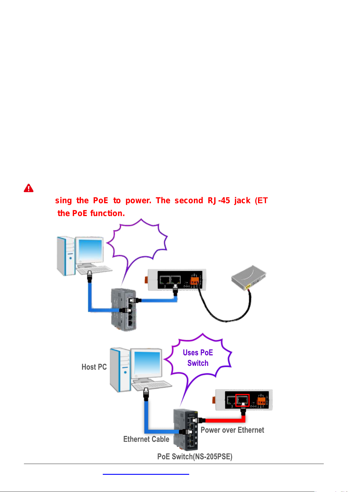
Connecting the Power and Host PC
1
1) Make sure the network of your PC is functioning appropriately.
Make sure your Windows firewall and Anti-Virus firewall is set accurately
(or you can temporarily disable the Windows firewall or Anti-Virus
firewall). The “Search Servers” on Chapter 5 may not work if the settings
are incorrect. (Please contact your system Administrator if you have
problem)
2) Connect the GW-2200 and your PC to the same sub network or the same
Ethernet switch.
3) Connect power supply (PoE or +12 to +48 VDC) to the GW-2200.
Note : Please use the first RJ-45 jack (ETH1) to connect the PoE Switch
when using the PoE to power. The second RJ-45 jack (ETH2) doesn’t
support the PoE function.
Technical support: service@icpdas.com P2
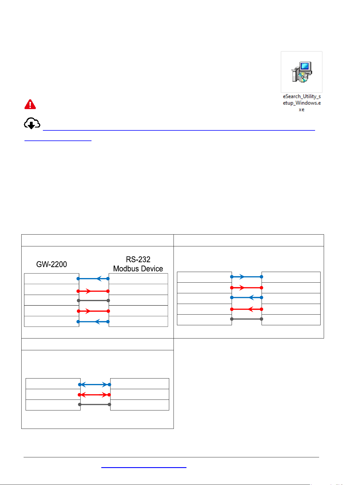
RS-232 Wiring
RS-422 Wiring
RS-485 Wiring
RxD
TxD
TxD
RxD
GND
GND
RTS
CTS
CTS
RTS
GW-2200
RS-422
Modbus Device
TxD+
RxD+
TxD-
RxD-
RxD+
TxD+
RxD-
TxD-
GND
GND
GW-2200
RS-485
Modbus Device
Data+
Data+
Data-
Data-
GND
GND
Installing Software on Your PC
2
Install eSearch Utility (it can be obtained from the
web site as below):
Note: The version of the eSearch Utility must be v1.2.5 or later.
https://www.icpdas.com/en/product/guide+Software+Utility_Driver+
eSearch__Utility
Wiring Notes
3
Wiring Notes for RS-232/485/422 Interfaces:
: The following RS-232 and RS-485 wiring deployment as an example.
Technical support: service@icpdas.com P3

Connecting the Modbus Devices
4
1) Connect the Modbus device (e.g., M-7022, optional) to the COM1 on GW-2200.
2) Supply power to the Modbus device (e.g., M-7022, Device ID:1).
Note: The wiring deployment of the device and power supply may vary
depends on your Modbus device.
RS-485 Wiring
RS-232 Wiring
Technical support: service@icpdas.com P4

IPv4 settings
Wirtable
IP Address
192.168.255.1
Subnet Mask
255.255.0.0
Gateway
192.168.0.1
IPv6 settings
Wirtable
User-defined
fc00::1
Link-Local
EUI-64 format
SLAAC
Auto-Configure
Configuring Network Settings
5
1) Double-click the eSearch Utility shortcut on the desktop.
2) Click the “Search Servers” to search your GW-2200.
Factory Default Settings of GW-2200:
Technical support: service@icpdas.com P5

Use the default
password: admin
3) Right Click on the Link-Local field and click the “Copy to Clipboard” to copy
the “Link-Local address” of the GW-2200 module.
4) Paste the “Link-Local address” of the GW-2200 module in the address bar
of the browser and add the brackets, i.e., [Link-Local address].
Note: The Web button only use the IPv4 address to access the Web
Server.
6
1) Enter the password in the login password field and click “Submit”.
Technical support: service@icpdas.com P6
Configuring the Serial Port

2) Click the “Port1” tab to display the “Port1 Settings” page.
3) Select the appropriate Baud Rate, Data Format and Modbus Protocol
(e.g., 19200, 8N2 and Modbus RTU) from the relevant drop down options.
Note: The settings of Baud Rate, Data Format or Modbus protocol will
depend on your Modbus device.
4) Click “Submit” to save your settings.
Self-Test
7
1) Download and install the “Modbus Poll” test program from the link as
below: https://www.modbustools.com/download.html
2) Double-click the Modbus Poll shortcut to open.
3) Select the “Read/Write Definition…” from the “Setup” menu to open the
“Read/Write Definition” dialog box.
4) Configure the settings for the Slave.
Note: The settings of the Modbus Slave will depend on your Modbus
device.
Technical support: service@icpdas.com P7

5) Select the “Connect…” from the “Connection” menu to open the
“Connection Setup” dialog box.
6) Configure the IPv6 address and TCP port (default : 502) of GW-2200 and
click “OK” to connect the GW-2200 for testing.
7) If the response data is correct, it means the test is successful.
Technical support: service@icpdas.com P8
 Loading...