

Page 1

I
G-4510 Series
User’s Manual
Power Saving PAC (with solar charger)
Version 1.1.1 December 2020
Service and usage information for
G-4510
Series
Page 2

II
Warranty
All products manufactured by ICP DAS are under warranty regarding
defective materials for a period of one year, beginning from the date
of delivery to the original purchaser.
Warning
ICP DAS assumes no liability for any damage resulting from the use of
this product. ICP DAS reserves the right to change this manual at any
time without notice. The information furnished by ICP DAS is believed
to be accurate and reliable. However, no responsibility is assumed by
ICP DAS for its use, not for any infringements of patents or other
rights of third parties resulting from its use.
Copyright
Copyright @ 2020 by ICP DAS Co., Ltd. All rights are reserved.
Trademark
The names used for identification only may be registered trademarks
of their respective companies.
Contact US
If you have any problem, please feel free to contact us. You can count on us for
quick response.
Email: service@icpdas.com
Page 3

III
Table of Contents
1. Introduction ............................................................................... 1
2. Hardware Specifications ........................................................... 2
2.1 G-4510 Series ....................................................................................... 2
2.2 G-4510 Series Specifications ................................................................ 3
2.3 Order Accessories Specifications .......................................................... 5
3. Application Architecture ........................................................... 6
3.1 Hydrologic / Wind Monitoring Application .............................................. 6
3.2 Car Monitor / Tracking System .............................................................. 6
3.3 Redundancy Communication system .................................................... 7
4. Hardware .................................................................................... 8
4.1 Pin Assignments .................................................................................... 8
4.2 Dimensions ........................................................................................... 9
4.3 Operation Mode Switch ....................................................................... 10
4.4 LED Indicators ......................................................................................11
4.5 Wire Connection .................................................................................. 12
4.6 Wake up from Sleep Mode .................................................................. 13
4.7 Assembly process ............................................................................... 14
4.8 Installation ........................................................................................... 17
5. Power Saving and Charger ..................................................... 18
5.1 Power Saving ...................................................................................... 18
5.2 How to Choose the Battery ................................................................. 20
5.3 How to Choose the Solar Panel .......................................................... 23
6. APIs and Demo References .................................................... 26
6.1 API for Local I/O ................................ .................................................. 26
6.1.1 X305IO_Init ............................................................................... 27
6.1.2 X305IO_GetLibVersion ............................................................. 28
6.1.3 X305IO_Read_AD_CalibrationGain .......................................... 29
6.1.4 X305IO_Read_AD_CalibrationOffset ........................................ 30
6.1.5 X305IO_AnalogIn ...................................................................... 31
6.1.6 X305IO_Read_All_DI ................................................................ 32
6.1.7 X305IO_Read_One_DI ............................................................. 33
6.1.8 X305IO_Write_All_DO .............................................................. 34
6.1.9 X305IO_Write_One_DO............................................................ 35
6.1.10 X305IO_Read_All_DO ............................................................ 36
6.1.11 X305IO_Read_One_DO.......................................................... 37
6.1.12 X305IO_AnalogIn_SetChannel ............................................... 38
Page 4

IV
6.1.13 X305IO_AnalogIn_Hex ........................................................... 39
6.1.14 X305IO_AnalogIn_HexToFloat ................................................ 40
6.2 API for MMC/SD .................................................................................. 41
6.3 API for LCD ......................................................................................... 46
6.3.1 LCD_Init .................................................................................... 47
6.3.2 LCD_BackLight_On .................................................................. 48
6.3.3 LCD_BackLight_Off .................................................................. 49
6.3.4 LCD_ShowText ......................................................................... 50
6.3.5 LCD_ClrScrn ............................................................................. 51
6.3.6 LCD_StandByMode ................................................................... 52
6.3.7 LCD_NormalMode .................................................................... 53
6.3.8 LCD_GotoPosition .................................................................... 54
6.3.9 LCD_CursorDisplay .................................................................. 55
6.3.10 LCD_LineReverse ................................................................... 56
6.3.11 LCD_LineRestore .................................................................... 57
6.3.12 LCD_GetLibDate ..................................................................... 58
6.3.13 LCD_GetLibVersion ................................................................ 59
7. Program Download Procedure ............................................... 60
8. Revision History ...................................................................... 66
Page 5

G-4510 Series User’s Manual v1.1.1
- 1/64 -
1. Introduction
The G-4510 series are M2M (Machine to Machine) Power Saving PAC with a cellular
transceiver and Solar Charger. It can be used in hydrologic monitoring or mudslide
monitoring system. With optional GPS model, the G-4510 can also be a GPS tracking
system for vehicle management system or maritime system.
The features of G-4510 series: Solar Charger, Ethernet interface, optional GPS
module, 3 digital inputs, 3 digital outputs, 8 analog inputs, 1 relay, 1 RS-232 and 1 RS-485
port. G-4510 can be used in various application fields to transfer data over 4G, 3G, GPRS,
SMS, Ethernet or serial bus through its optional 4G / NB communication module. The
G-4510 series built-in MiniOS7 provide the same development environment with
I-7188/I-7186 series. It is easier for I-7188/I-7186 users to apply the G-4510 series.
Page 6
G-4510 Series User’s Manual v1.1.1
- 2/64 -
2. Hardware Specifications
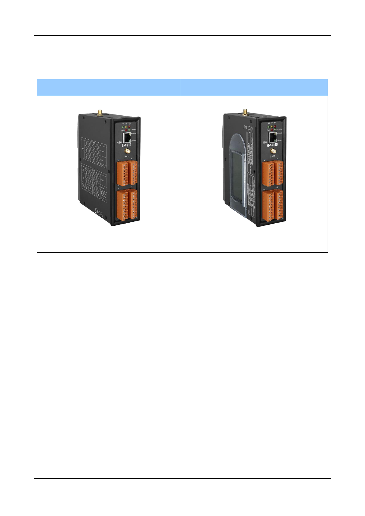
2.1 G-4510 Series
G-4510
G-4510D
Page 7

G-4510 Series User’s Manual v1.1.1
- 3/64 -
2.2 G-4510 Series Specifications
Hardware Specification
Item
G-4510
G-4510D
CPU
80 MHz internal microprocessor
SRAM/Flash
512K/512K , real time clock, watchdog timer
NVRAM
31 bytes, battery backup, data valid up to 10 years
EEPROM
16 KB, retention > 40 years. 1,000,000 erase/write cycles
Comm. Interface
COM ports
COM1:5-wire RS-232; COM2: RS-485
Ethernet
10/100 Base-TX Ethernet controller
Digital Input
Input Channel
3
Input Type
Source(Dry Type), Common Ground
Off Voltage Level
+1 V max.
On Voltage Level
+3.5 ~ +30 V
Isolated Voltage
Non-isolated
Digital Output
Output Channel
3
Output Type
3 Open Collector (Sink/NPN)
Load Voltage
+30 VDC max.
Load Current
100 mA max.
Isolated Voltage
Non-isolated
Analog Input
Input Channel
8
Resolution
12 - bit
Input Range/Type
0 ~ 20 mA
Sample Rate
1 KHz max. (Read one channel)
Accuracy
+/- 2 LSB (+/- 0.0097 mA)
Isolated Voltage
2500Vrms 3000Dc to DC
Relay
Output Channel
1
Type
Form C
Input Range
2A@30 Vdc ; 0.25 A @250 Vac
Mechanical
endurance
typ. 108 operations
GPS Interface
Support Channels
32
Sensitivity
Tracking = up to -159 dBm (with external LNA)
Cold start = up to -146 dBm (with external LNA)
Acquisition Time
Hot start (Open Sky) = 2 s(typical)
Cold start (Open Sky) = 36 s(typical)
Protocol Support
NMEA 0183 version 3.01
LCD Interface
General
Effective
display
area
-
80.61 mm x 14.37 mm (W x H)
Module
Dimension
-
93 mm x 70 mm x 1.6 mm (W x H x T)
Life Time
-
Expected life is more than 100,000 hours
under normal operation
Power (Solar Input)
Protection
Power reverse polarity protection
Frame Ground
Protection
ESD, Surge, EFT, Hi-Pot
Page 8

G-4510 Series User’s Manual v1.1.1
- 4/64 -
Power Requirement
+10 VDC ~ +30 V
DC ,
(Max. Voltage of Solar Panel must less +30V)
Power Consumption
Deep Sleep: < 10 mA@12VDC;
Deep Sleep(With LCD): < 11 mA@12VDC;
Sleep: < 15 mA@12V
DC;
Idle: 90 mA @ 24 VDC;
Data Link: 150 ~ 400 mA (peak) @ 24 VDC
Lead Acid Battery Requirement
Battery
12V Lead-Acid Battery
Charging Voltage
Voltage of Power Input must be over +16V
Low Voltage Protect
Low Voltage disconnect = 11.1V / Low Voltage reconnect = 12.6V
LED Indicators
System
Red
4G
Yellow
GPS
Green
Charging / Fault
Green / Red
Mechanical
Casing
Metal
Dimensions
47 mm x 142 mm x 168 mm (W x L x H)
Installation
DIN-Rail and Wall mount
Environment
Operating
Temperature
-20 ~ +70 °C
-15 ~ +55 °C
Storage
Temperature
-40 ~ +80 °C
-20 ~ +70 °C
Humidity
5~90% RH, non-condensing
Page 9

G-4510 Series User’s Manual v1.1.1
- 5/64 -
2.3 Order Accessories Specifications
Hardware Specification
Module(Optional)
EC21-AU
EC25-E
BG96
Category
LTE category 1
LTE category 4
LTE Cat-M1/NB1/EGPRS
Frequency Bands
LTE-FDD
B1/B2/B3/B4/B5/B7/B8/B28
B1/B3/B5/B7/B8/B20
B1/B2/B3/B4/B5/B8/B12/B13/B18/
B19/B20/B26/B28
LET-TDD
B40
B38/B40/B41
B39 (For Cat M1 Only)
WCDMA
B1/B2/B5/B8
B1/B5/B8
--
GSM/EGPRS
850/900/1800/1900MHz
900/1800Mhz
850/900/1800/1900MHz
Area
Region
Latin America, Australia,
New Zeland, Taiwan
EMEA, Korea, Thailand,
India
Global
Certification
Carrier:Telstra
Regulatory:FCC
/Anatel/NCC/JATE/TELEC/
RCM
Others:WHQL
Carrier:
Vodafone/Deutsche
Telekom/
SKT/Telefónica/T-Mobile/KT/
LGU+
Regulatory:
GCF/ CE/ KC/ NCC/ RCM/
FAC/ NBTC/ ICASA
Others:
WHQL
Carrier:
Vodafone (Global)
Deutsche Telekom
Telefónica(Europe)/
Verizon/AT&T/T-Mobile/Sprint/
U.S. Celluar (North America)
Telus/Rogers /Bell (Canada)
SKT/LGU+ (South Korea)
NTT DOCOMO/SoftBank
/KDD(Japan)/Telstra (Australia)
Regulatory:
GCF (Global),CE (Europe)
FCC/PTCRB (North America)
IC (Canada)
IFETEL (Mexico)
CCC (China)
KC (South Korea)
NCC (Taiwan)
JATE/TELEC (Japan)
RCM (Australia)
NBTC (Thailand)
IMDA (Singapore)
Others:
RoHS Compliant
Environment
Temperature
Range
-40°C ~ +80°C
-40°C ~ +85°C
-40°C ~ +80°C
Dimensions
51.0mm × 30.0mm × 4.9mm
Page 10
G-4510 Series User’s Manual v1.1.1
- 6/64 -
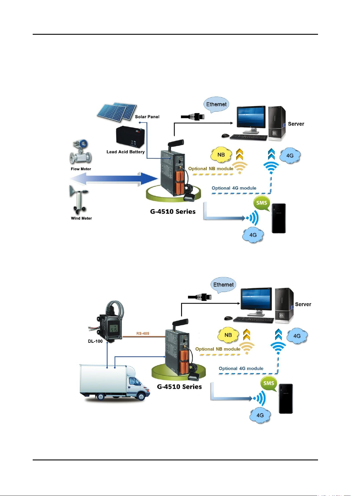
3. Application Architecture
3.1 Hydrologic / Wind Monitoring Application
3.2 Car Monitor / Tracking System
Page 11
G-4510 Series User’s Manual v1.1.1
- 7/64 -
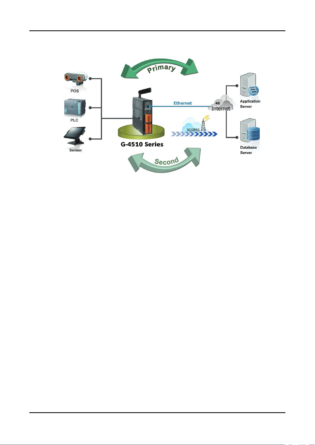
3.3 Redundancy Communication system
Page 12
G-4510 Series User’s Manual v1.1.1
- 8/64 -
4. Hardware
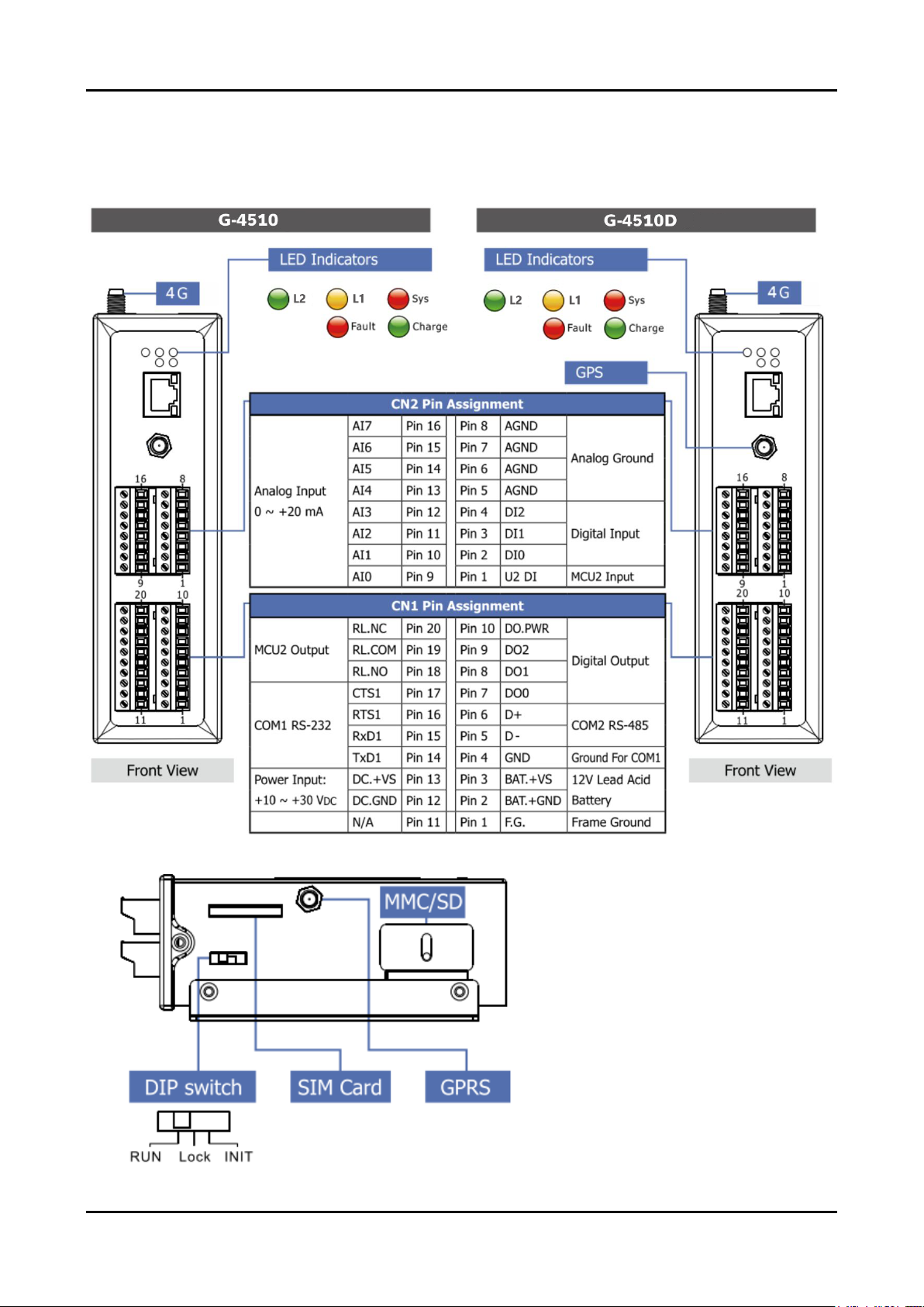
4.1 Pin Assignments
Page 13
G-4510 Series User’s Manual v1.1.1
- 9/64 -
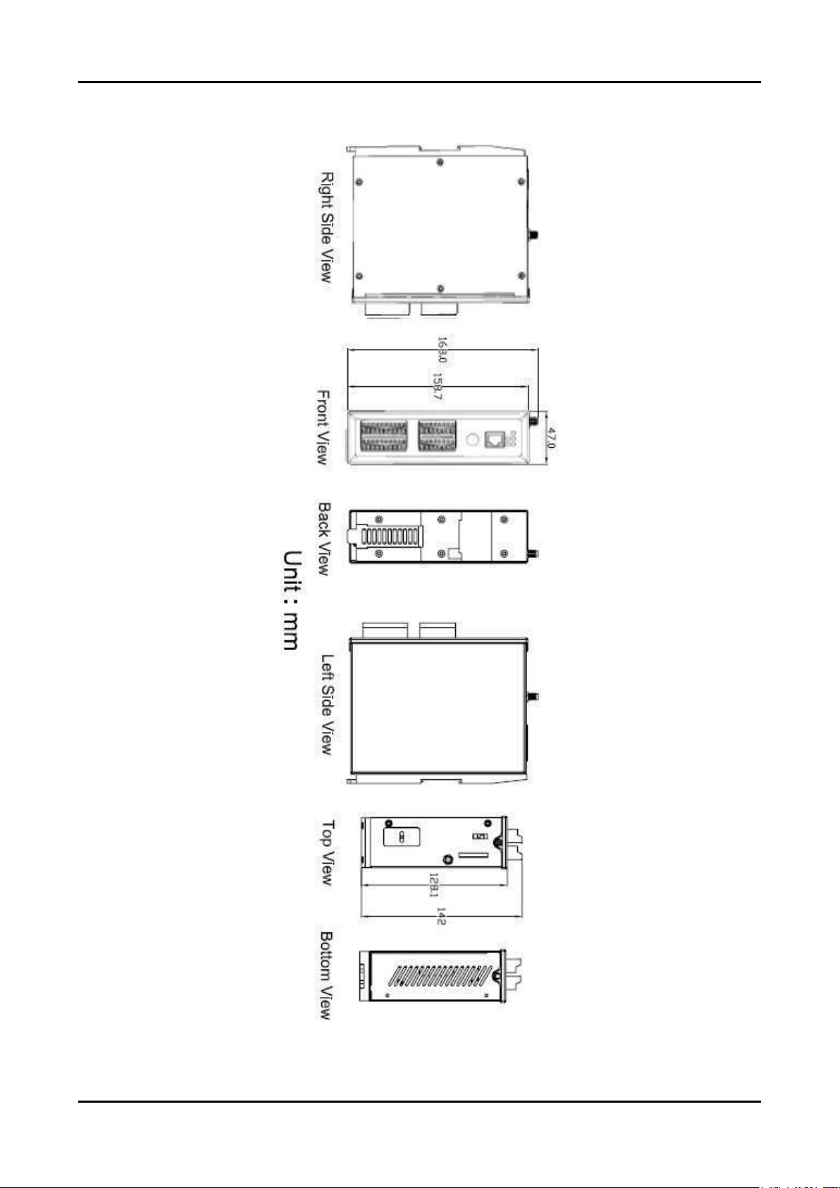
4.2 Dimensions
Page 14
G-4510 Series User’s Manual v1.1.1
- 10/64 -
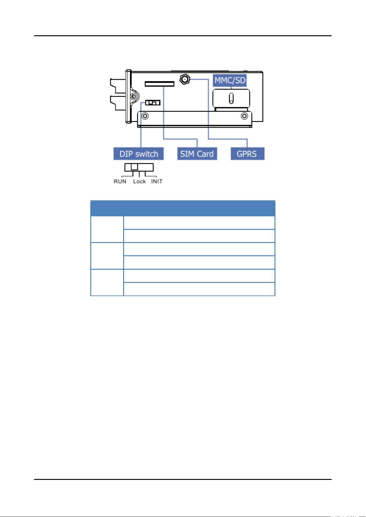
4.3 Operation Mode Switch
Operation Mode Switch
RUN
OS can execute autoexec.bat
Flash can be read/write.
Lock
OS can execute autoexec.bat
Flash is read only (lock).
INIT
OS can not execute autoexec.bat
Flash can be read/write.
Page 15
G-4510 Series User’s Manual v1.1.1
- 11/64 -
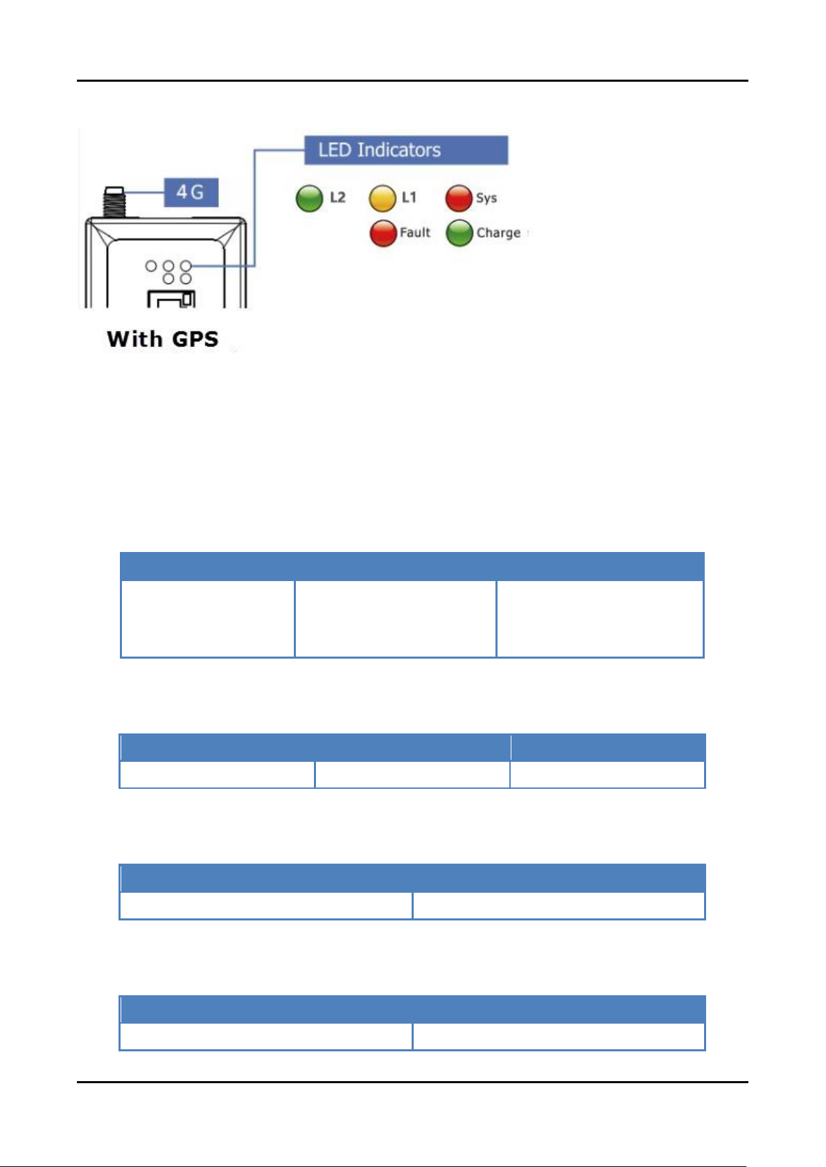
4.4 LED Indicators
There are five LED indicators to help users to judge the various conditions of G-4510
Series. The description is as follows:
A. Sys (Red):System LED is programmable.
B. L1 (Yellow):The modem LED can indicate the status of 4G module.
4G Module Normal
4G Module Exception
Data Transmission
ON 2 sec and OFF 1
sec
OFF
or
ON 1 sec and OFF 2 sec
Blinking (0.2 sec)
C. L2 (Green)(Option):The GPS LED can indicate the status of GPS module.
GPS Fail
Search GPS
Receive GPS data
Always OFF
Always ON
Blinking (1 sec)
D. Charging (Green):Charging status indicator.
Charging
Not Charging
Always ON
Always OFF
E. Fault (Red):Charging Fault indicator.
Normal
Fault
Always OFF
Always ON
Page 16
G-4510 Series User’s Manual v1.1.1
- 12/64 -
4.5 Wire Connection
Digital Input Wire Connection
Input Type
ON State
DI value as 0
OFF State
DI value as 1
Relay Contact
TTL/CMOS
Logic
Open Collector
Digital Output Wire Connection
Input Type
ON State
DO value as 1
OFF State
DO value as 0
Drive Relay
Resistance
Load
Page 17
G-4510 Series User’s Manual v1.1.1
- 13/64 -
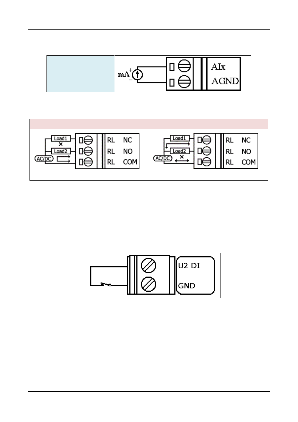
Current Input Wire Connection
Input Type
Relay Wire connection
Relay Output ON
Relay Output OFF
4.6 Wake up from Sleep Mode
1. When G-4510 was in sleep mode, you can connect the Pin “U2 DI” (MCU2 DI) to GND.
to awaking G-4510 from sleep mode.
2. You will read “U2 DI” as 0, when you connect “U2 DI” to GND.
Page 18

G-4510 Series User’s Manual v1.1.1
- 14/64 -
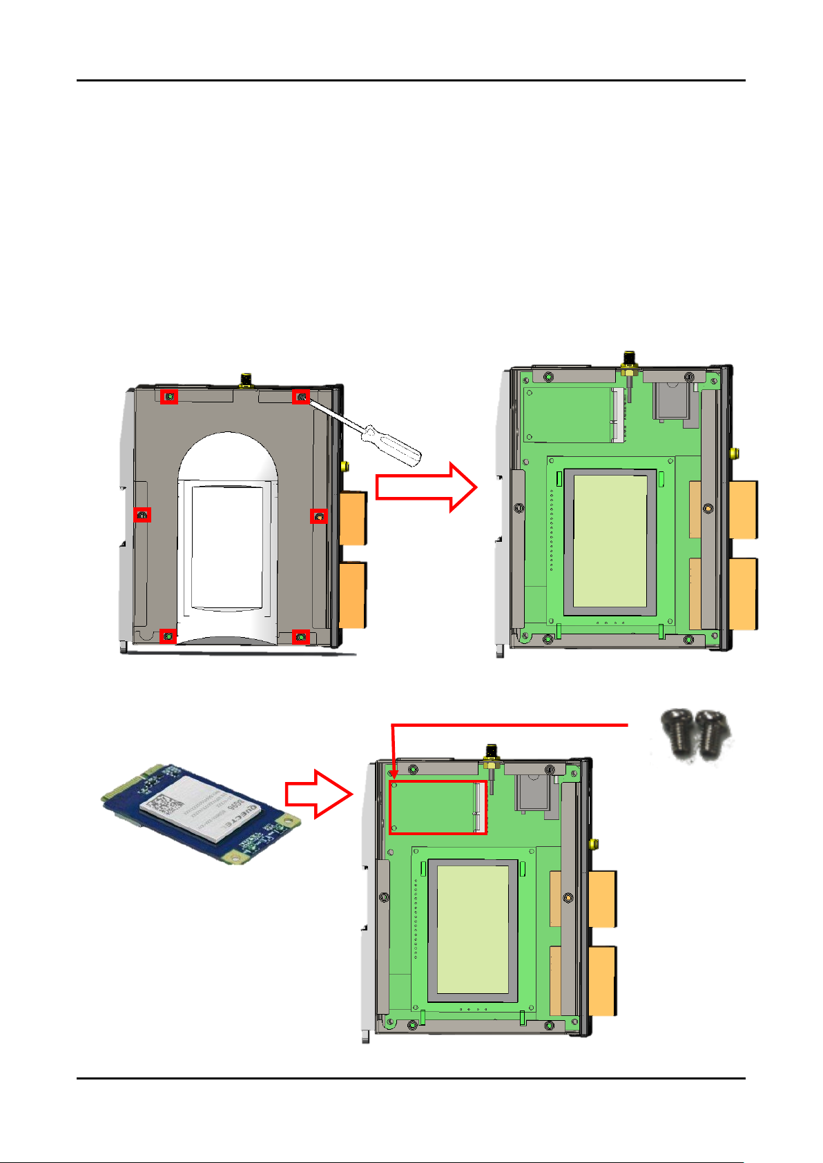
4.7 Assembly process
Assembling exploded drawing
Page 19
G-4510 Series User’s Manual v1.1.1
- 15/64 -
When purchase the communication module EC21-AU, EC25-E or BG96, please refer
to the following installation methods for installation:
※
EC21-AU, EC25-E and BG96 please refer to the ordering information at the
bottom of the G-4510 ordering page.
1. Remove the 6 screws on the quick release board and remove the quick release board
2. Insert the communication module into the PCI-E slot and lock the screws
3. Connect the 4G Ipex plug to the communication module Main position
4. Install the quick release board and lock the 6 screws on the quick release board
Step 1
Step 2
Communication module
PCI-E screws
Page 20

G-4510 Series User’s Manual v1.1.1
- 16/64 -
Step 3
4G Ipex plug
Step 4
Casing screws
Page 21
G-4510 Series User’s Manual v1.1.1
- 17/64 -
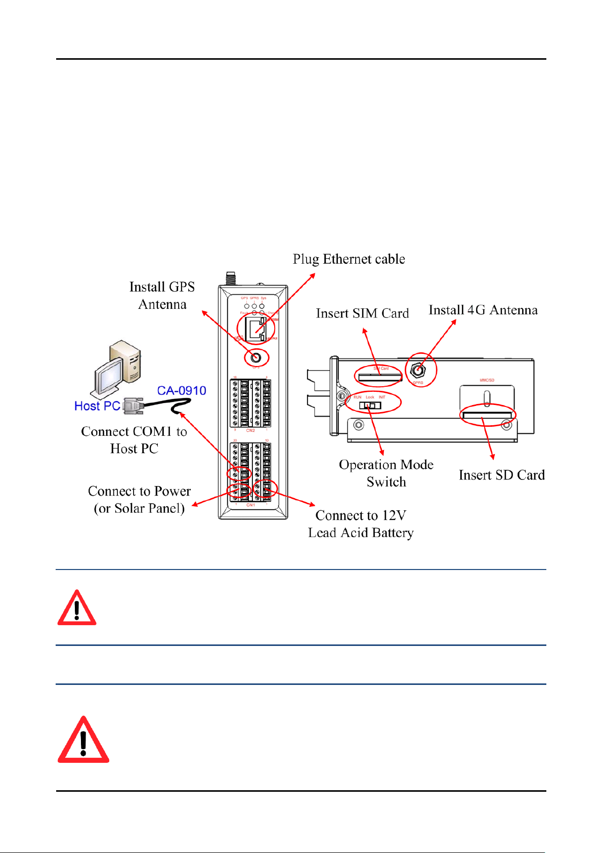
4.8 Installation
1. Install 4G antenna. (Installed in ANT1 position)
※ANT2 is the GPS antenna installation position
2. Plug in the normal SIM card (Before apply the SIM card, confirm it is OK by mobile
phone.)
3. Connect the DC.+VS and DC.GND to the power supply or Solar Panel.
4. Connect BAT.+VS and BAT.GND to the 12V Lead Acid Battery.
WARNING! HOT SURFACE DO NOT TOUCH
The product’s enclosure may be with high temperature, do not touch before
cooling or else will be burned.
SAFETY INSTRUCTION NOTES
The unit installation to final system and the DC source (SELV, Limited Power
Source) that is intended to connect with power input pins (DC.+VS / DC.GND)
should be complied with requirements of EN 60950-1. Be sure before connect
to input pins.
Page 22

G-4510 Series User’s Manual v1.1.1
- 18/64 -
5. Power Saving and Charger
5.1 Power Saving
Sleep Mode
This mode will shut down 7186 CPU, all I/O(3DI, 3DO, 8AI, exclude MCU2 I/O) and
GPS, but 4G module still works.
Power Consumption:14~15 mA@12V
How to awake G-4510:
(1) Sleeping Time is finished.
(2) Trigger U2_DI.(connect U2_DI to GND.; read U2_DI as 0)
(3) Make a phone call to G-4510
Deep Sleep Mode
This mode will shut down all interface, but exclude MCU2 I/O.
Power consumption:9~10 mA@12V
How to awake G-4510:
(1) Sleeping Time is finished.
(2) Trigger U2_DI.(connect U2_DI to GND.; read U2_DI as 0)
Page 23

G-4510 Series User’s Manual v1.1.1
- 19/64 -
Low Voltage Protection
Default value is disabled, and you can enable this function by your program. This
function will prevent the battery to over-discharging. When the voltage of the battery is
less 11.1V, G-4510 will go into Low Voltage Protect Mode that will turn off all system
power. And then G-4510 will wake up if the voltage of the battery is over 12.6V after
charging.
Low Voltage disconnect Voltage = 11.1 V
Low Voltage reconnect Voltage = 12.6 V
How to use:please refer to the figure’s wire connection below, and MCU2 library
demo code.
Page 24

G-4510 Series User’s Manual v1.1.1
- 20/64 -
5.2 How to Choose the Battery
This section will discuss how to choose a suitable battery for your system. Because the
alive time of the system is depending on your system power consumption and your battery
capacity, we will calculate with some conditions below.
Example 1:
Conditions:
The system has a 24V external power
It must work in 2 week when the external power is shut-down.
The system transmits the data to the server every 10 minutes. (1 minute for full work,
and 9 minutes for sleeping)
Power consumption of deep sleep mode is 7.2 mA@12V
Average power consumption of full work is 245 mA@12V
Calculation:
Average power consumption = 245 x (1/10) + 7.2 x (9/10) = 31 (mA)
31 (mA) x 24 (hours) x 14 (days) = 10416 mAh
We may choose “12V, 14Ah Lead Acid Battery” for this system.
Because 10% battery capacity is low battery voltage state, we don’t work in this state.
We use 90% battery capacity to calculate.
Double check the battery capacity:
14Ah x 90% x 1000 = 12600 mAh > 10416 mAh
We will choose a “12V, 14Ah Lead Acid Battery” for this system.
Page 25

G-4510 Series User’s Manual v1.1.1
- 21/64 -
Please refer Table 5.2.1 to choose the battery for other report frequency:
Table 5.2.1
Report Frequency
Average power
consumption
power consumption of 14
days (mAh @12V)
Every minute
(No Sleep)
245
82320
Every 10 minutes
31
10416
Every hour
11.2
3763.2
Every day
7.4
2486.4
Every Month
7.2
2419.2
Example 2:
Conditions:
The system has a 24V external power.
It must work in 2 week when the external power is shut-down.
The system transmits 3 Modbus devices data to the server every 10 minutes. (1 minute
for full work, and 9 minutes for sleeping)
The system will power off all Modbus devices by “MCU2 Relay Output” when it’s
in Deep Sleep Mode.
Power consumption of deep sleep mode is 7.2 mA@12V
Average power consumption of full work is 424 mA@12V
Calculation:
Average power consumption = 424 x (1/10) + 7.2 x (9/10) = 49 (mA)
424 (mA) x 24 (hours) x 14 (days) = 16430.4 mAh
Page 26

G-4510 Series User’s Manual v1.1.1
- 22/64 -
We may choose “12V, 22Ah Lead Acid Battery” for this system.
Because 10% battery capacity is low battery voltage state, we don’t work in this state.
We use 90% battery capacity to calculate.
Double check the battery capacity:
22Ah x 90% x 1000 = 19800 mAh > 16430.4 mAh
We will choose a “12V, 22Ah Lead Acid Battery” for this system.
Please refer Table 5.2.2 to choose the battery for other report frequency:
Table 5.2.2
Report Frequency
Average power
consumption
power consumption of 14
days (mAh @12V)
Every minute
(No Sleep)
424
142464
Every 10 minutes
48.9
16430.4
Every hour
14.1
4737.6
Every day
7.5
2520
Every Month
7.2
2419.2
Page 27

G-4510 Series User’s Manual v1.1.1
- 23/64 -
5.3 How to Choose the Solar Panel
This section will discuss how to choose a suitable solar panel for your system. The
power of solar panel must be more than the power consumption of the system, and we will
calculate with some conditions below.
Things you must know before you calculate
Charging voltage:must be more than +16V
Max. Charge Current:2A
Sun hours:an average value. If the average daily solar radiation of the area is 3
kW/m2 , the sun hours of this area is 3 hours
Example:
Conditions:
Power consumption of deep sleep mode is 7.2 mA@12V
Average power consumption of the system is 245 mA@12V
The system transmits the data to the server every 10 minutes. (1 minute for full work,
and 9 minutes for sleeping)
Sun hours is 4 hours/day.
Using 10W solar panel
Page 28

G-4510 Series User’s Manual v1.1.1
- 24/64 -
Calculation:
Solar panel Max. current = 10 (w) / 12 (V) = 0.833 (A) = 833 (mA)
Usually the charging current may be effected by many factor, like angle, building and
other environment factor…etc.
Here we use 1/2 Max. current to calculate
1/2 Max. Current = 833/2 = 416 mA
Average current = 416 x 4 / 24 = 69 (mA/hr)
Refer to Table 5.3.2, We can know “Average power consumption” is 31 mA for this
system. (refer to Table 5.3.2 or section 5.2)
We can know 10W solar Panel is suitable for this system, because 69 > 31
Table 5.3.1
Solar panel
(W)
Max. Current
(mA)
1/2 Current
(mA)
Sun hours
Average Current for a day
(mA/hr)
10
833
416 4 69
20
1666
833 4 138
30
2500
1250 4 208
40
3333
1666 4 277
50
4166
2083 4 347
Table 5.3.2
Report Frequency
Average power
consumption
power consumption of 14
days (mAh @12V)
Every minute
(No Sleep)
245
82320
Every 10 minutes
31
10416
Every hour
11.2
3763.2
Every day
7.4
2486.4
Every Month
7.2
2419.2
Page 29

G-4510 Series User’s Manual v1.1.1
- 25/64 -
Things you must know about “sun hours”
Usually the “sun hours” is variable with the season. You need use the Min. sun
hours to calculate and choose the solar panel and the battery.
For example, if the sun hours of month is like the figure below, you must use 2.2
hours to calculate but not 6.7 hours.
Page 30

G-4510 Series User’s Manual v1.1.1
- 26/64 -
6. APIs and Demo References
6.1 API for Local I/O
Function definition
Description
X305IO_Init
Initial I/O
X305IO_GetLibVersion
Get X305IO_LIB Version
X305IO_Read_AD_CalibrationGain
Read AD Calibration Gain
X305IO_Read_AD_CalibrationOffset
Read AD Calibration Offset
X305IO_AnalogIn
Read value from assign AI channel
X305IO_Read_All_DI
Read All DI
X305IO_Read_One_DI
Read the value form assign DI channel
X305IO_Write_All_DO
Write All DO
X305IO_Write_One_DO
Write the value to the assign DO channel
X305IO_Read_All_DO
Read All DO state
X305IO_Read_One_DO
Read the DO state form the assign DO
channel.
X305IO_AnalogIn_SetChannel
Set the AI channel that users want to read.
X305IO_AnalogIn_Hex
Read the value from the specific A/D channel
(12 bits)
X305IO_AnalogIn_HexToFloat
Transfer the AI value from 12 bits to float
Page 31

G-4510 Series User’s Manual v1.1.1
- 27/64 -
6.1.1 X305IO_Init
Initial X305IO.
Syntax
int X305IO_Init(void);
Parameters
None
Return values
0:success
<>0:error
Page 32

G-4510 Series User’s Manual v1.1.1
- 28/64 -
6.1.2 X305IO_GetLibVersion
Get X305IO_Lib Version.
Syntax
unsigned X305IO_GetLibVersion(void);
Parameters
None
Return values
Version Number
Page 33

G-4510 Series User’s Manual v1.1.1
- 29/64 -
6.1.3 X305IO_Read_AD_CalibrationGain
Read the A/D Calibration Gain.
Syntax
float X305IO_Read_AD_CalibrationGain(void);
Parameters
None
Return values
Calibration Gain of the AD channels
Page 34

G-4510 Series User’s Manual v1.1.1
- 30/64 -
6.1.4 X305IO_Read_AD_CalibrationOffset
Read the A/D Calibration Offset.
Syntax
float X305IO_Read_AD_CalibrationOffset(void);
Parameters
None
Return values
Calibration Offset of the AD channels
Page 35

G-4510 Series User’s Manual v1.1.1
- 31/64 -
6.1.5 X305IO_AnalogIn
Read the value from the assign AI channel.
Syntax
float X305IO_AnalogIn(
int iChannel
);
Parameters
iChannel
0:channel 0
1:channel 1
2:channel 2
3:channel 3
4:channel 4
5:channel 5
6:channel 6
7:channel 7
Return values
0.0mA ~ 20.0mA
Page 36

G-4510 Series User’s Manual v1.1.1
- 32/64 -
6.1.6 X305IO_Read_All_DI
Read all DI values of the G-4510 series.
Syntax
int X305IO_Read_All_DI(void);
Parameters
None
Return values
0x00~0x07
Example
When DI0 Ground
DI1 Open
DI2 Open
value = X305IO_Read_All_DI( );
value = 0x6
Page 37

G-4510 Series User’s Manual v1.1.1
- 33/64 -
6.1.7 X305IO_Read_One_DI
Read the value from the assign DI channel.
Syntax
int X305IO_Read_One_DI(
int iChannel
);
Parameters
iChannel
0:channel 0
1:channel 1
2:channel 2
Return values
1:open
Logic high level (+3.5V ~ +30V)
0:close to GND
Logic low level (0V ~ +1V)
Page 38

G-4510 Series User’s Manual v1.1.1
- 34/64 -
6.1.8 X305IO_Write_All_DO
Write to all DO values of the G-4510 series.
Syntax
void X305IO_Write_All_DO(
int iOutValue
);
Parameters
iOutValue
0x0~0x7
Return values
None
Example
X305IO_Write_All_DO(6);
After function execute:
DO0 OFF
DO1 ON
DO2 ON
Page 39

G-4510 Series User’s Manual v1.1.1
- 35/64 -
6.1.9 X305IO_Write_One_DO
Write the specific value to the assign DO channel.
Syntax
void X305IO_Write_One_DO(
int iChannel, int iStatus
);
Parameters
iChannel
0:channel 0
1:channel 1
2:channel 2
iStatus
0:Status is OFF
1:Status is ON
Return values
None
Page 40

G-4510 Series User’s Manual v1.1.1
- 36/64 -
6.1.10 X305IO_Read_All_DO
Read all DO values of the G-4510 series.
Syntax
int X305IO_Read_All_DO(void);
Parameters
None
Return values
0x0~0x7
Example
When DO0 OFF
DO1 ON
DO2 ON
Value = X305IO_Read_All_DO( );
Value = 0x6
Page 41

G-4510 Series User’s Manual v1.1.1
- 37/64 -
6.1.11 X305IO_Read_One_DO
Read the state from the assign DO channel.
Syntax
int X305IO_Read_One_DO(
int iChannel
);
Parameters
iChannel
0:channel 0
1:channel 1
2:channel 2
Return values
0:OFF
1:ON
Page 42

G-4510 Series User’s Manual v1.1.1
- 38/64 -
6.1.12 X305IO_AnalogIn_SetChannel
Set the specific AI channel that users want to read.
Syntax
int X305IO_AnalogIn_SetChannel(
unsigned iChannel
);
Parameters
iChannel
0:channel 0
1:channel 1
2:channel 2
3:channel 3
4:channel 4
5:channel 5
6:channel 6
7:channel 7
Return values
0:Set up success
-1:Set iChannel number error
Page 43

G-4510 Series User’s Manual v1.1.1
- 39/64 -
6.1.13 X305IO_AnalogIn_Hex
Read the value of the assign AI channel assigned by X305IO_AnalogIn_SetChannel
function.
Syntax
int X305IO_AnalogIn_Hex(void);
Parameters
None
Return values
After Read assign AI channel value.
Example
X305IO_AnalogIn_SetChannel(0); // Set channel 0
X305IO_AnalogIn_Hex( );
Page 44

G-4510 Series User’s Manual v1.1.1
- 40/64 -
6.1.14 X305IO_AnalogIn_HexToFloat
Set the AI value from 12 bits to float format.
Syntax
float X305IO_AnalogIn_HexToFloat(
int iValue
);
Parameters
iValue
A value want to 12 bits transform float.
Return values
The transferred AI value by float format.
Example
Set the channel 0 to read, and then transform the value to float.
float AdValue;
X305IO_AnalogIn_SetChannel(0);
AdValue=X305IO_AnalogIn_HexToFloat(X305IO_AnalogIn_Hex( ));
Page 45

G-4510 Series User’s Manual v1.1.1
- 41/64 -
6.2 API for MMC/SD
Required library and header files:
SD_Vnnn.LIB and microSD.h
Function definition
Description
pc_init
Initializes the SD socket library
pc_open
1. Open an existing file and return a file handle
2. Creates a new file
pc_close
Closes a file and release a file handle.
pc_read
Reads the specified file
pc_write
Writes the specified file
pc_seek
Moves the file pointer to relative offset from the
current offset
pc_tell
Gets current offset of the file pointer
pc_eof
Checks whether the end‐of‐file is reached
pc_format
Formats the SD card as FAT (FAT32)
pc_mkdir
Creates a directory or subdirectory
pc_rmdir
Removes an existing directory
pc_move
Renames an existing file or a directory, including
the subdirectory
pc_del
Deletes the specified file
pc_deltree
Deletes the specified directory or subdirectory
pc_isdir
Checks whether the file is a directory
pc_isvol
Checks if is a volume
pc_size
Gets the size of the specified file
pc_set_cwd
Sets the current working directory
Page 46

G-4510 Series User’s Manual v1.1.1
- 42/64 -
pc_get_cwd
Gets the pathname of the current working directory
pc_gfirst
Moves the pointer to the first element
pc_gnext
Moves the pointer to the next element
pc_gdone
Moves the pointer to the last element
pc_get_freeSize_KB
Gets the free space of the SD memory card
pc_get_usedSize_KB
Gets the used space of the SD memory card
pc_get_totalSize_KB
Gets the total size of the SD memory card
pc_get_attributes
Gets the file attributes
pc_set_attributes
Sets the file attributes
pc_get_errno
Gets the error number
API for starting SD card
1. pc_ Init()
Before using any SD functions, pc_init() must be called to initialize the SD.
API for enabling/disabling SD card
2. pc_open()
Before writing/reading data to/from the SD card, pc_open() must be called to open the
file.
3. pc_close()
After the data has finished being written/read to/from the SD, pc_close() must be called
to close the file with a file handle.
API for writing data to the SD card
4. pc_write()
After using pc_open() to open the file, pc_write() must be called to read data from the
SD.
Page 47

G-4510 Series User’s Manual v1.1.1
- 43/64 -
For example, writing data to the SD:
#include <string.h>
#include <stdio.h>
#include "upac5000.h"
#include "microSD.h"
void main(void)
{
int fd, iRet;
InitLib();
if(pc_init())
Print(“Init microSD ok\r\n”);
else
{
Print(“Init microSD failed\r\n”);
iRet=pc_get_errno();
switch(iRet)
{
case PCERR_BAD_FORMAT: //1
Print("Error 01: format is not FAT\r\n");
break;
case PCERR_NO_CARD: //2
Print("Error 02: no microSD card\r\n");
break;
default:
Print("Error %02d: unknow error\r\n", iRet);
break;
}
}
fd=pc_open("test.txt", (word) (PO_WRONLY|PO_CREAT|PO_APPEND),
(word) (PS_IWRITE|PS_IREAD));
if(fd>=0)
{
pc_write(fd, "1234567890", 10); /* write 10 bytes */
pc_close(fd);
}
}
Page 48

G-4510 Series User’s Manual v1.1.1
- 44/64 -
API for reading data from the SD card
5. pc_read()
After using pc_open() to open the file, pc_read() must be called to read data from the
SD.
For example, reading data from the SD:
#include <string.h>
#include <stdio.h>
#include "upac5000.h"
#include "microSD.h"
void main(void)
{
int fd, iRet;
unsigned char Buffer[80];
InitLib();
if(pc_init())
Print("Init microSD ok\r\n");
else
{
Print("Init microSD failed\r\n");
iRet=pc_get_errno();
switch(iRet)
{
case PCERR_BAD_FORMAT: //1
Print("Error 01: format is not FAT\r\n");
break;
case PCERR_NO_CARD: //2
Print("Error 02: no microSD card\r\n");
break;
default:
Print("Error %02d: unknow error\r\n", iRet);
break;
}
}
fd=pc_open("test.txt", (word) (PO_RDONLY), (word) (PS_IWRITE|PS_IREAD));
if(fd>=0)
{
iRet=pc_read(fd, Buffer, 10); /* reads 10 bytes */
Page 49

G-4510 Series User’s Manual v1.1.1
- 45/64 -
Buffer[10]=0; /* adds zero end to the end of the string */
pc_close(fd);
Print("%s", Buffer);
}
}
For more demo program about the microSD, please refer to:
CD:\napdos\g-4510\software\demo\basic\microSD\
http://ftp.icpdas.com/pub/cd/usbcd/napdos/g-4510/software/demo/basic/microsd/
Page 50

G-4510 Series User’s Manual v1.1.1
- 46/64 -
6.3 API for LCD
Function definition
Description
LCD_Init
Initialize the library
LCD_BackLight_On
Turn on the LCD backlight
LCD_BackLight_Off
Turn off the LCD backlight
LCD_ShowText
Display one character on the LCD panel
LCD_ClrScrn
Clear the LCD panel
LCD_StandByMode
Enter the stand by mode
LCD_NormalMode
Restore the LCD to normal mode
LCD_GotoPosition
Move the cursor to the specified position
LCD_CursorDisplay
Set the Cursor display status
LCD_LineReverse
Select one of four line and reverse the display
LCD_LineRestore
Select one of four line and restore the display
LCD_GetLibDate
Gets the create date of funciton library
LCD_GetLibVersion
Gets the version number of function library
Page 51

G-4510 Series User’s Manual v1.1.1
- 47/64 -
6.3.1 LCD_Init
Initialize parameters about LCD functions in the library.
Syntax
void LCD_Init(void);
Parameters
None
Return values
None
Page 52

G-4510 Series User’s Manual v1.1.1
- 48/64 -
6.3.2 LCD_BackLight_On
Turn on the LCD backlight.
Syntax
void LCD_BackLight_On(void);
Parameters
None
Return
None
Page 53

G-4510 Series User’s Manual v1.1.1
- 49/64 -
6.3.3 LCD_BackLight_Off
Turn off the LCD backlight.
Syntax
void LCD_BackLight_Off(void);
Parameters
None
Return values
None
Page 54

G-4510 Series User’s Manual v1.1.1
- 50/64 -
6.3.4 LCD_ShowText
Display one character on the LCD panel, and the cursor will right-shifted by one
character position automatically.
Syntax
void LCD_ShowText(
uchar Text
);
Parameters
Text
Display character
Return values
None
Page 55

G-4510 Series User’s Manual v1.1.1
- 51/64 -
6.3.5 LCD_ClrScrn
Clear the LCD panel.
Syntax
void LCD_ClrScrn(void);
Parameters
None
Return values
None
Page 56

G-4510 Series User’s Manual v1.1.1
- 52/64 -
6.3.6 LCD_StandByMode
Enter the stand by mode, and it can be terminated by either LCD_NormalMode() or
other function.
Syntax
void LCD_StandByMode(void);
Parameters
None
Return values
None
Page 57

G-4510 Series User’s Manual v1.1.1
- 53/64 -
6.3.7 LCD_NormalMode
Restore the LCD to normal mode when it is in the stand by mode.
Syntax
void LCD_NormalMode(void);
Parameters
None
Return values
None
Page 58

G-4510 Series User’s Manual v1.1.1
- 54/64 -
6.3.8 LCD_GotoPosition
Move the cursor to the specified position.
Syntax
void LCD_GotoPosition(
int Line,
int Offset
);
Parameters
Line
One of four line numbers (1 to 4)
Offset
Cursor position (1 to 8)
Return values
None
Page 59

G-4510 Series User’s Manual v1.1.1
- 55/64 -
6.3.9 LCD_CursorDisplay
Set the Cursor display status.
Syntax
void LCD_CursorDisplay(
int Display,
int Blink
);
Parameters
Display
Cursor display on/off
1: Display on
0: Display off
Blink
Character blink on/off
1: Display on
0: Display off
Return values
None
Page 60

G-4510 Series User’s Manual v1.1.1
- 56/64 -
6.3.10 LCD_LineReverse
Select one of four line and reverse the display.
Syntax
void LCD_LineReverse(int Line);
Parameters
Line
One of four line numbers (0 to 4)
Return values
None
Page 61

G-4510 Series User’s Manual v1.1.1
- 57/64 -
6.3.11 LCD_LineRestore
Select one of four line and restore the display.
Syntax
void LCD_LineRestore(
int Line
);
Parameters
Line
One of four line numbers (0 to 4)
Return values
None
Page 62

G-4510 Series User’s Manual v1.1.1
- 58/64 -
6.3.12 LCD_GetLibDate
Gets the create date of funciton library.
Syntax
void LCD_GetLibDate(
unsigned char *LibDate
);
Parameters
LibDate
Gets the create date of funciton library
Return values
None
Page 63

G-4510 Series User’s Manual v1.1.1
- 59/64 -
6.3.13 LCD_GetLibVersion
Get the version number of function library.
Syntax
unsigned LCD_GetLibVersion(void);
Parameters
None
Return values
Return the current version number.
Page 64

G-4510 Series User’s Manual v1.1.1
- 60/64 -
7. Program Download Procedure
Here, it is considered that how to build an execution file and how to run this program on
the G-4510 series.
Library
Description
G4500.LIB
G-4510 and DI/O、AI functions
GSM.LIB
GPRS functions
SD_Vnnn.LIB
MMC/SD functions
TCP_DM32.LIB
Ethernet functions
LCD.LIB
LCD functions
Step 1:Create a folder name “MyDemo” in the C disk, and copy the lib folder and users
program into the MyDemo folder.
Page 65

G-4510 Series User’s Manual v1.1.1
- 61/64 -
Step 2:Run the TC++1.01development. Click the “Project\Open project…” create new
project named “TEST.PRJ”.
Step 3:Use the “Add” function to add the library file into MyDemo project.
Page 66

G-4510 Series User’s Manual v1.1.1
- 62/64 -
Step 4:Following the step3, add another library and TEST.C into MyDemo project.
Step 5:Click the “Options/Compiler/Code generation…” to set the compile mode to the
large mode. Click “More…” to set the “Floating point” and “ Instruction Set”
parameters. The Emulation and 80186 will be used respectively. Then, click OK button to
save the configuration.
Page 67

G-4510 Series User’s Manual v1.1.1
- 63/64 -
Step 6:Click the “Option/Debugger... ” to set the “Source Debugging” parameter.
Here, select the “None” for the “Source Debugging”.
Step 7:Click the “Option/Directories... ” to set the “Output Directory” parameter.
Here, set the “C:\MyDemo” for the “Output Directory” parameter.
Page 68

G-4510 Series User’s Manual v1.1.1
- 64/64 -
Step 8:After finishing all the parameters setting, click the “Compile/build all” to produce
the execution file name “TEST.exe”.
Step 9: Copy the file 7188XW.exe into the MyDemo folder. Then, double-click the
7188XW.exe file.The 7188XW.exe can be found in the Osimage folder. And G-4510 series
COM1 connected to the PC RS-232.
Page 69

G-4510 Series User’s Manual v1.1.1
- 65/64 -
Step 10:Key the command, “load” in the 7188xw.exe program. Then, follow the hint
command to press “Alt+E” and input the file name, “TEST.exe”, to download the
execution file.
Step 11: After finishing the download procedure, key in the command, “run” , to
implement the execution file, “TEST.exe”.
Page 70

G-4510 Series User’s Manual v1.1.1
- 66/64 -
8. Revision History
Revision
Date
Author
Description
1.0.0
2020/02/10
Amon
Release version
1.1.0
2020/08/12
Amon
Modfiy optional module & GPS.
1.1.1
2020/12/23
Amon
Modfiy model number
 Loading...