

Page 1
ET-7H24 Series
User Manual
Version 1.0.0, Aug 2020
Written by Sean Hsu
Edited by Anna Huang
Page 2

Warranty
All products manufactured by ICP DAS are under warranty regarding defective materials for a
period of one year, beginning from the date of delivery to the original purchaser.
Warning
ICP DAS assumes no liability for any damage resulting from the use of this product. ICP DAS
reserves the right to change this manual at any time without notice. The information
furnished by ICP DAS is believed to be accurate and reliable. However, no responsibility is
assumed by ICP DAS for its use, not for any infringements of patents or other rights of third
parties resulting from its use.
Copyright
Copyright @ 2020 by ICP DAS Co., Ltd. All rights are reserved.
Trademark
The names used for identification only may be registered trademarks of their respective
companies.
Contact US
If you have any problem, please feel free to contact us.
You can count on us for quick response.
Email: service@icpdas.com
PET-7H24M Series User Manual, version 1.0.0 P.2
Page 3

Table of Contents
1. Introduction .............................................................................................. 5
1.1. Features ......................................................................................................................... 6
1.2. Specification ................................................................................................................ 12
1.3. Overview ..................................................................................................................... 15
1.4. Wiring Diagram ............................................................................................................ 20
1.5. Block Diagram .............................................................................................................. 22
1.6. Dimension.................................................................................................................... 23
2. Getting Started ........................................................................................ 24
2.1. Mounting the Hardware .............................................................................................. 25
2.2. Deploying a Basic PET-7H24M System ........................................................................ 26
2.3. Installing the HSDAQ Utility ......................................................................................... 28
2.4. Using HSDAQ Utility to Assign an IP address ............................................................... 29
3. Operation ................................................................................................ 32
3.1. Continuous Acquisition ............................................................................................... 33
Software AD Trigger ............................................................................................. 33 3.1.1.
3.2. N Sample Acquisition .................................................................................................. 35
Software AD Trigger ............................................................................................. 35 3.2.1.
Analog Input Trigger ............................................................................................. 36 3.2.2.
4. Tools and SDKs ........................................................................................ 38
4.1. LabVIEW ...................................................................................................................... 38
4.2. HSDAQ Utility .............................................................................................................. 39
4.3. SDK API ........................................................................................................................ 41
5. Web Applications .................................................................................... 47
5.1. Overview ..................................................................................................................... 49
PET-7H24M Series User Manual, version 1.0.0 P.3
Page 4

5.2. Configuration ............................................................................................................... 50
Network Settings .................................................................................................. 51 5.2.1.
Basic Settings........................................................................................................ 52 5.2.2.
5.3. Authentication ............................................................................................................. 58
Account Management .......................................................................................... 59 5.3.1.
Accessible IP Settings ........................................................................................... 63 5.3.2.
5.4. Web HMI...................................................................................................................... 67
6. Modbus Applications .............................................................................. 68
7. Updates ................................................................................................... 72
8. Calibration .............................................................................................. 75
Appendix B. Analog Input Type and Data Format Table ............................... 83
Appendix C. Troubleshooting ...................................................................... 84
Appendix D. Revision History ...................................................................... 85
PET-7H24M Series User Manual, version 1.0.0 P.4
Page 5
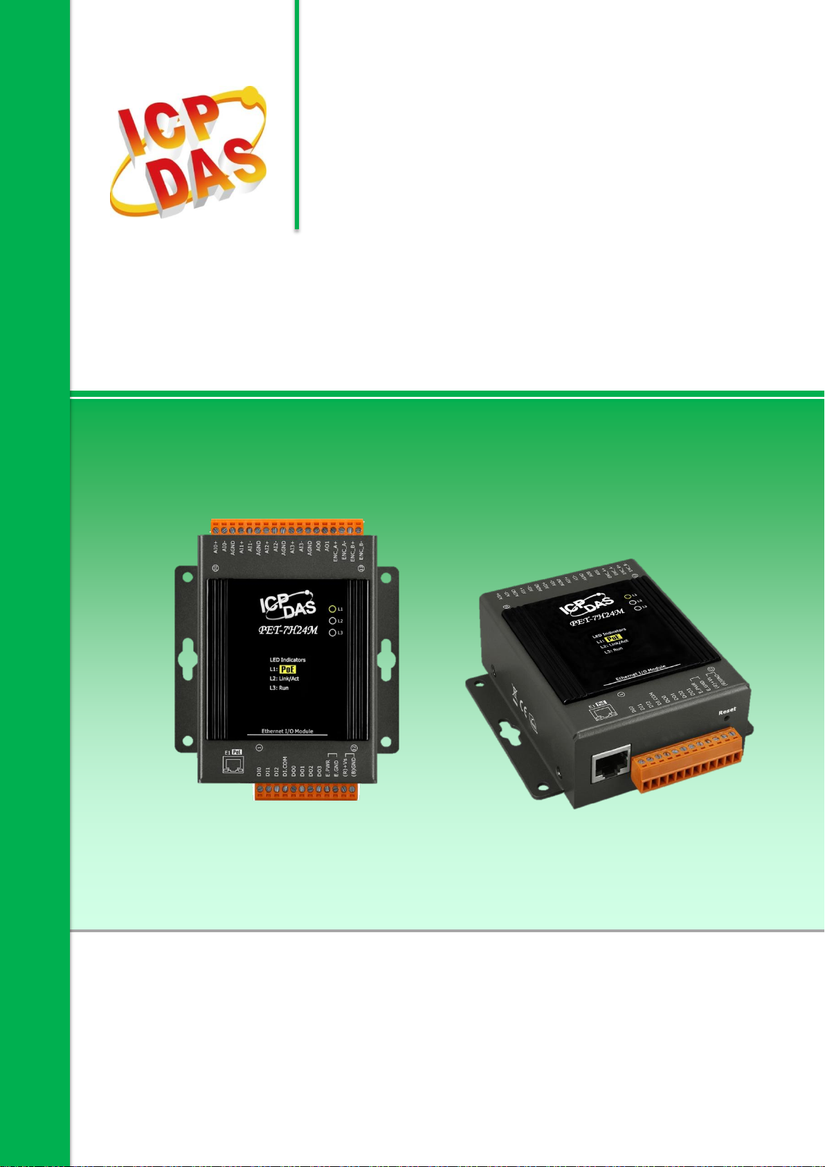
1. Introduction
The PET-7H24M is an high speed data acquisition devices built-in a Ethernet communication port
for data transfer over the network and it includes 4 high-speed 24-bit differential Analog input
channels analog inputs (128 KHz sample and hold for 4 channels), 2 Analog Output channels, 3
Digital Input channels, 4 Digital Output channels and 1 Encoder Input channel. The module
provides a programmable input range on all analog channels, and the Digital Output can be set to
output with short-circuit and over load protection. 1 Encoder Input channel can be configured as
Quadrant, Pulse/Direction or CW/CCW input mode. The PET-7H24M also provides 4 kV ESD
protection as well as 2500 VDC intra-module isolation. In addition, the 24-bit ADC includes built-in
Sinc3 filtering to adjust the appropriate sampling rate and filter out modulator and signal noise.
The PET-7H24M is not only suitable for a wide range of mobile/portable measurement
applications, but also for precision signal measurement.
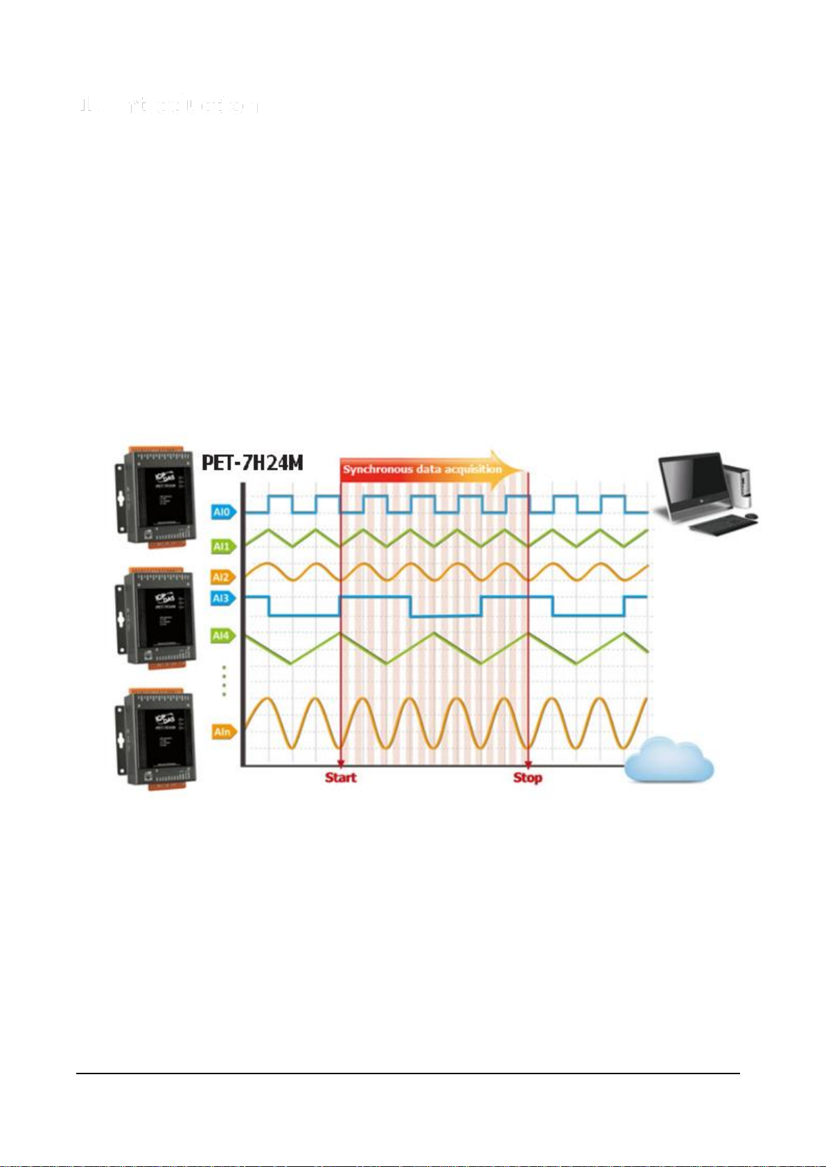
PET-7H24M supports more kinds of trigger modes for A/D conversion: software trigger, analog
Input trigger. The software trigger can acquire a sample whenever needed, Analog input trigger
mode, when the analog input value is higher or lower than the set specific voltage value, it triggers,
and the A/D collection of N data is started.
PET-7H24M Series User Manual, version 1.0.0 P.5
Page 6

Total simultaneous sampling channels
Maximum sampling rate per channel
2~4
60 KHz
1.1. Features
The PET-7H24M series family offers the most comprehensive configuration to meet specific
application requirements. The following list shows the features designed to simplify installation,
configuration and application.
Data transmission mode
1. Continuous transmission (Maximum sampling rate of 60 kHz per channel)
After starting A/D acquisition, data is continuously transmitted to the Host PC.
2. After collecting N data samples, the data is transferred to the Host PC (Maximum sampling
rate of 128 kHz per channel)
a. After starting A/D acquisition, the data will be temporarily stored in the memory on the
PET-7H24M module, and wait until a command is received from the Host PC, before
transferring the collected data to the Host PC.
b. The memory capacity allows temporary storage of up to 30 million data samples,
Storage time:
(b1) 125 seconds at a sampling rate of 60 kHz
(b2) 62.5 seconds at a sampling rate of 128 kHz
PET-7H24M Series User Manual, version 1.0.0 P.6
Page 7

Total simultaneous sampling channels
Maximum sampling rate per channel
1 ~ 4
128 KHz
A/D trigger mode
1. Software A/D Data Acquisition mode
The A/D acquisition parameters are configured via a command from the Host PC. The
continuous A/D acquisition or the acquisition of N data samples begins after the
command is triggered.
2. Analog Input Trigger mode
The A/D acquisition parameters are configured via a command from the Host PC, When
the analog input value is higher or lower than the set specific voltage value, the A/D
acquisition of the N data is started.
Analog Input Trigger
Analog Input Trigger is triggered when the voltage signal of the specified analog input
channel is higher or lower than a certain voltage setting. In addition, the user can also
specify the trigger voltage level range of the input signal. Once the signal leaves the high and
low level region or the signal enters the high and low level region, it is triggered to start the
acquisition.
1. Above High: The signal is triggered above the high level and collects N data.
2. Below Low: The signal is triggered below the low level and collects N data
PET-7H24M Series User Manual, version 1.0.0 P.7
Page 8
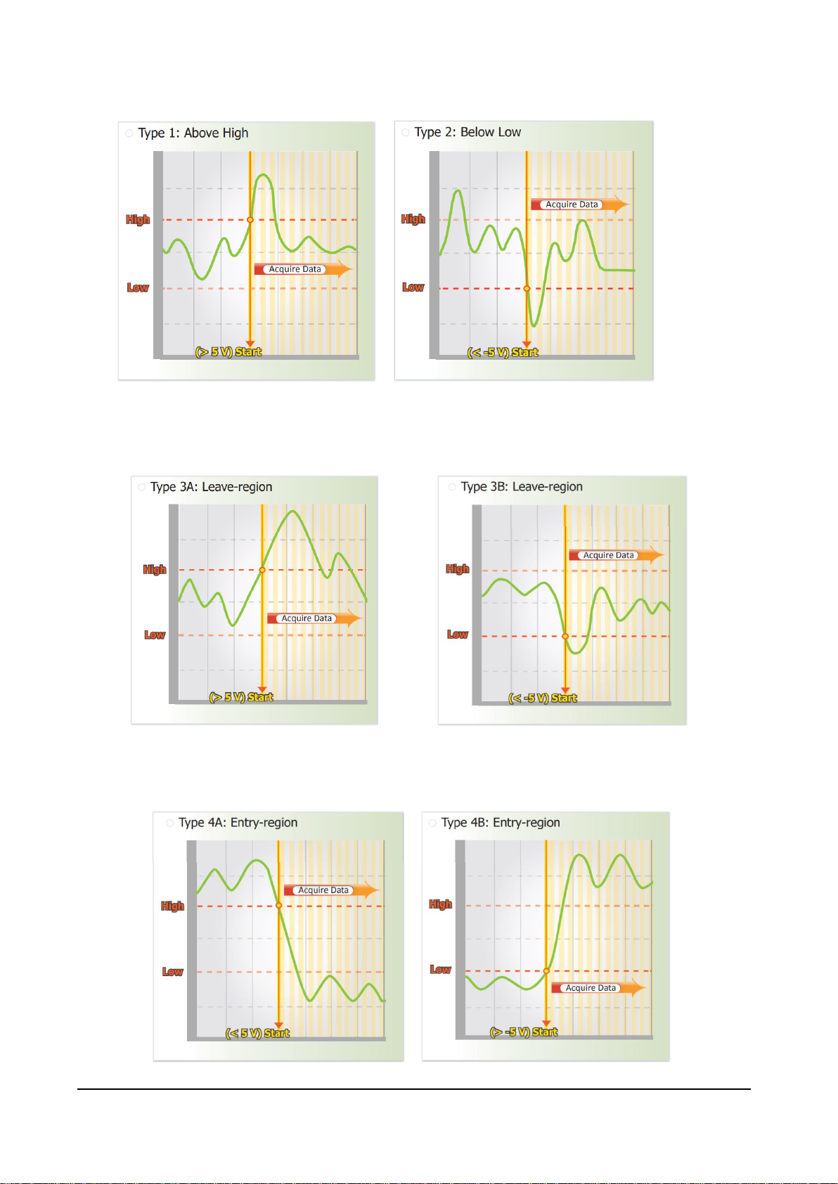
3. Leave-region: Trigger when the signal leaves the high and low level region, collect N data
4. Entry-region: Trigger when the signal enters the high and low level region, collect N data
PET-7H24M Series User Manual, version 1.0.0 P.8
Page 9
Built-in Web Server
Each PET-7H24M module has a built-in web server that allows users to easily configure,
monitor and control the module from a remote location using a regular web browser.
Communication Security
Account and password are required when logging into the PET-7H24M web server. An IP
address filter is also included, which can be used to allow or deny connections with specific
IP addresses.
Modbus/TCP Protocol
The Modbus/TCP slave function on the Ethernet port can be used to provide data to remote
HMI/SCADA software built with Modbus/TCP driver.
Automatic MDI / MDI-X Crossover for Plug-and-play
RJ-45 port supports automatic MDI/MDI-x that can automatically detect the type of
connection to the Ethernet device without requiring special straight or crossover cables.
PET-7H24M Series User Manual, version 1.0.0 P.9
Page 10
Software Support
Supported Operating Systems
Windows 7/8/10 and Linux
Software Compatibility
Microsoft VC, C#, VB.NET SDK API and Demo
NI LabVIEW Toolkit and Demo
C/C++ library and Demo for Linux
Highly Reliable Under Harsh Environment
PET-7H24M is housed in a metal shell/case with a column-like ventilator that helps to cool
the working environment inside the shell/case.
Operating Temperature: -25 ~ +75 °C
Storage Temperature: -30 ~ +80 °C
Humidity: 10 ~ 90% RH (non-condensing)
PoE
The PET-7H24M module has integrated Power-over-Ethernet (PoE), it allows power and data
to be carried over a single Ethernet cable, so a device can operate solely from the power it
receives through the data cable. This innovation allows greater flexibility in office design,
PET-7H24M Series User Manual, version 1.0.0 P.10
Page 11
higher efficiency in systems design, and faster turnaround time in set-up and
implementation. The PET-7H24M module feature true IEEE 802.3af-compliant (classification,
Class 1) Power over Ethernet (PoE) using both Ethernet pairs (Category 5 Ethernet cable).
The PET-7H24M module can receive power from an auxiliary power sources like AC adapters
and battery in addition to the PoE enabled network. This is a desirable feature when the
total system power requirements exceed the PSE's(power sourcing equipment) load capacity.
Furthermore, with the auxiliary power option, the PET-7H24M module can be used in a
standard Ethernet (non-PoE) system.
When using PoE devices like PET-7H24M, you can choose ICP DAS “PoE”
switch —”NS-205PSE” as the power source, NS-205PSE automatically detects the connected
devices whether they are PoE devices or not. This mechanism ensures NS-205PSE to work
with both PoE and non-PoE devices coordinately at the same time.
Being as a power source for PoE devices, NS-205PSE requires its power input ranging from
+46 ~ +55VDC.
PET-7H24M Series User Manual, version 1.0.0 P.11
Page 12

Communication
Ethernet Port
1 x RJ-45, 10/100 Base-TX (Auto-negotiating, Auto MDI/MDI-X)
PoE
Yes
Security
ID, Password and IP Filter
LED Indicators
for System Running
Yes
for Ethernet Link/Act
Yes
for POE Power
Yes
2-Way Isolation
I/O
2500 VDC
EMS Protection
ESD (IEC 61000-4-2)
+/-4 kV Contact for Each Terminal and +/-8 kV Air for Random
Point
EFT (IEC 61000-4-4)
+/-4 kV for Power
Power
Reverse Polarity Protection
Yes
Powered from Terminal Block
+12 ~ +48 VDC
Consumption
2.6 W (Max.)
Mechanical
Dimensions (W x L x H)
76 mm x 120 mm x 38 mm
Installation
DIN-Rail or Wall Mounting
Enclosures
Metal
Environment
Operating Temperature
-25 ~ +75 °C
Storage Temperature
-30 ~ +80 °C
Humidity
10 ~ 90 % RH, Non-condensing
1.2. Specification
The table below summarizes the specifications of the PET-7H24M.
System Specification
PET-7H24M Series User Manual, version 1.0.0 P.12
Page 13

Analog Input
Channels
4 Differential (Simultaneously)
Resolution
24-bit
Sampling Rate
128 KS/s (Each Channel)
Bipolar Input (Programmable)
+/- 10 V, +/- 5 V, +/- 2.5 V, +/- 1.25 V, +/- 0.625 V, ±300mV
±150mV ±75mV ±40mV ±20mV
FIFO Size
4 K Sample
Accuracy
+/- 0.01 % of FSR @±10V
+/- 0.02 % of FSR @±5V,±2.5V,±1.25V,±0.625V
+/- 0.1 % of FSR @±300mV, ±150mV, ±75mV, ±40mV
+/- 0.2 % of FSR @±20mV
AD Trigger Mode
(Programmable)
Software 、Analog Input trigger
Input Impedance
2M Ohm
Analog Output
Channels
2 Single-ended
Type
±10V, ±5V , ±0~5V, 0~10V
Resolution
12-bit
Accuracy
+/- 0.01 % of FSR @±10V, ±5V, 0~10V
+/- 0.02 % of FSR @0~5V
Output Capacity
10V @20mA
Slew Rate
0.83V/us
Digital Input
Channels
3
Contact
Wet Contact
Sink/Source (NPN/PNP)
Sink/Source
On Voltage Level
+5 VDC ~ 30 VDC
Off Voltage Level
2 VDC Max.
Input Impedance
10K Ohm
Isolation
2500 VDC
Digital Output
Channels
4
Type
Isolated Open Collector
I/O Specification
PET-7H24M Series User Manual, version 1.0.0 P.13
Page 14

Sink/Source(NPN/PNP)
Sink
Load Voltage
+5 VDC ~ 30 VDC
Load Current
100 mA at 25°C
Short-circuit Protection
Yes
Overload Protection
1.3A
Isolation
2500 VDC
Encoder Input
Counter
32-bit
Encoder Mode
Quadrant/CW/CCW and Pulse/Dir
Counting Rate
Quadrant Counting : 2MHz(Max.)
CW/CCW : 6MHz(Max.)
Pulse/Dir : 6MHz(Max.)
On Voltage Level
+3.5 ~+5 VDC
Off Voltage Level
+0.8 VDC Max.
Programmable digital filter
0.55 ~ 33.3μs (7 steps)
Isolation
2500 VDC
PET-7H24M Series User Manual, version 1.0.0 P.14
Page 15
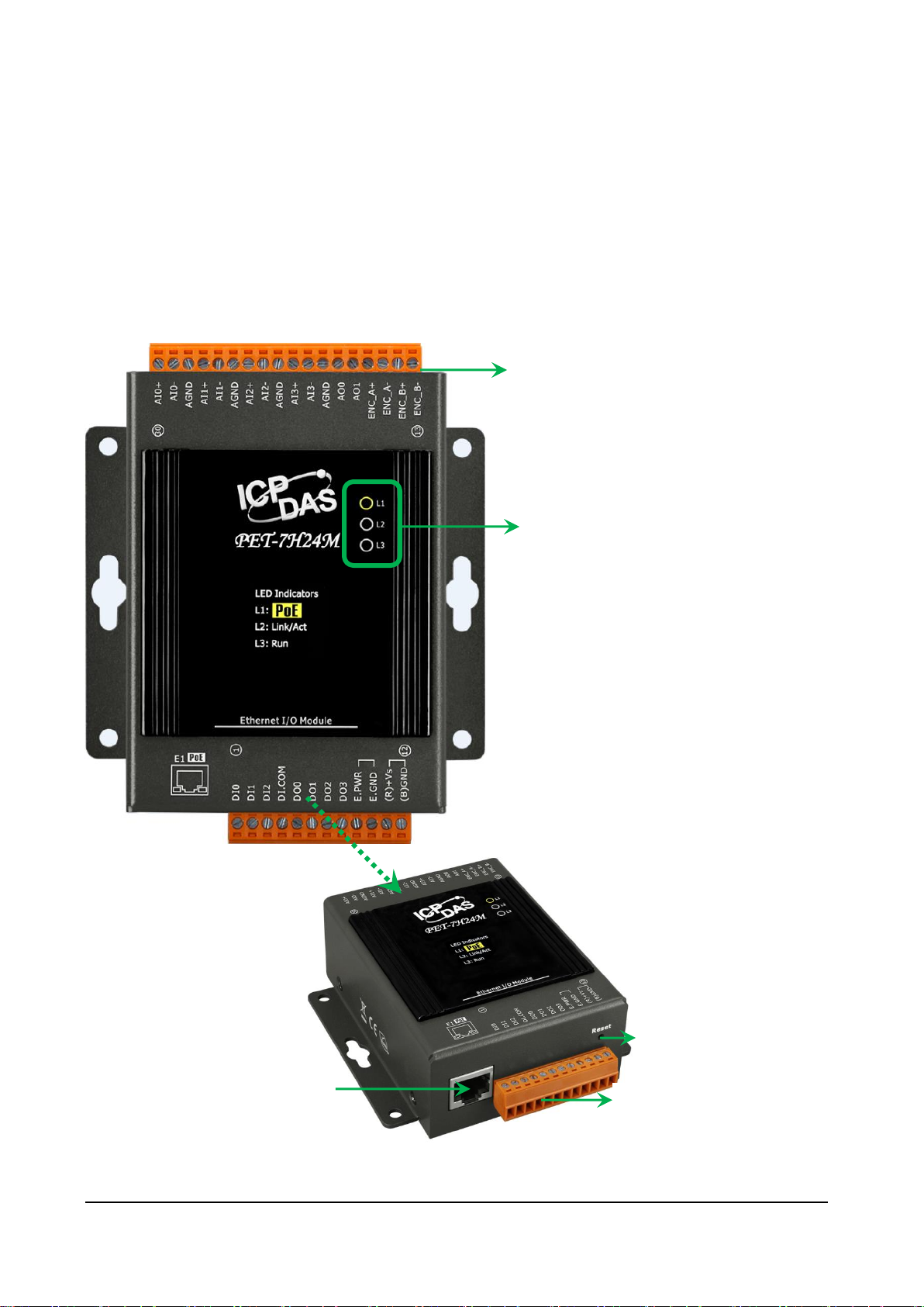
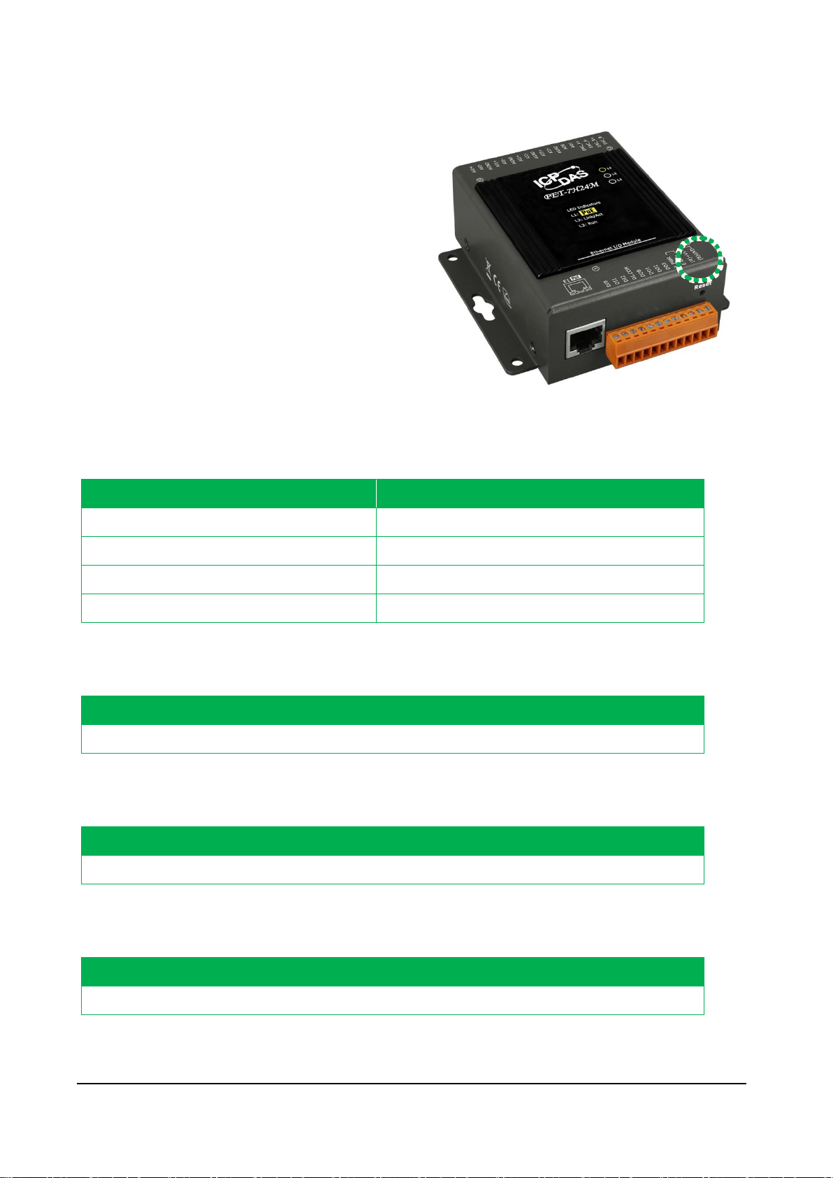
LED Indicators
J2 Connector (Pin 13 ~ 30)
Reset Button
J1 Connector (Pin 1 ~ 12)
Ethernet Port
1.3. Overview
PET-7H24M is equipped with several interfaces and peripherals that can be integrated with
external systems. Here is an overview of the components and its descriptions.
PET-7H24M Series User Manual, version 1.0.0 P.15
Page 16
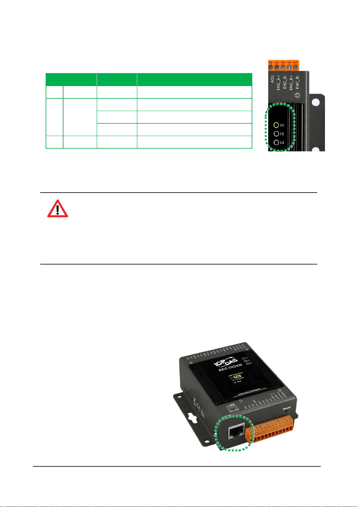
LED Indicator
LED Action
Meaning
L1
PoE
ON
When unit power is supplied via PoE.
L2
Link/ACT
ON
Ethernet link detected
OFF
No Ethernet link detected
Flashing
Ethernet packet received
L3
RUN
Flashing
Firmware is running
LED Indicators
The PET-7H24M has 3 LED indicators shown as below.
Tips & Warnings
If the Run LED does not display the information as above, the following steps
should be taken:
Step 1: Switch the power off
Step 2: Switch the power on and double-check the LED indicators
Ethernet Port
The PET-7H24M has an Ethernet port that can be connected to a computer or device via an
Ethernet cable.
The L2 indicators display the status of the
Ethernet port.
PET-7H24M Series User Manual, version 1.0.0 P.16
Page 17
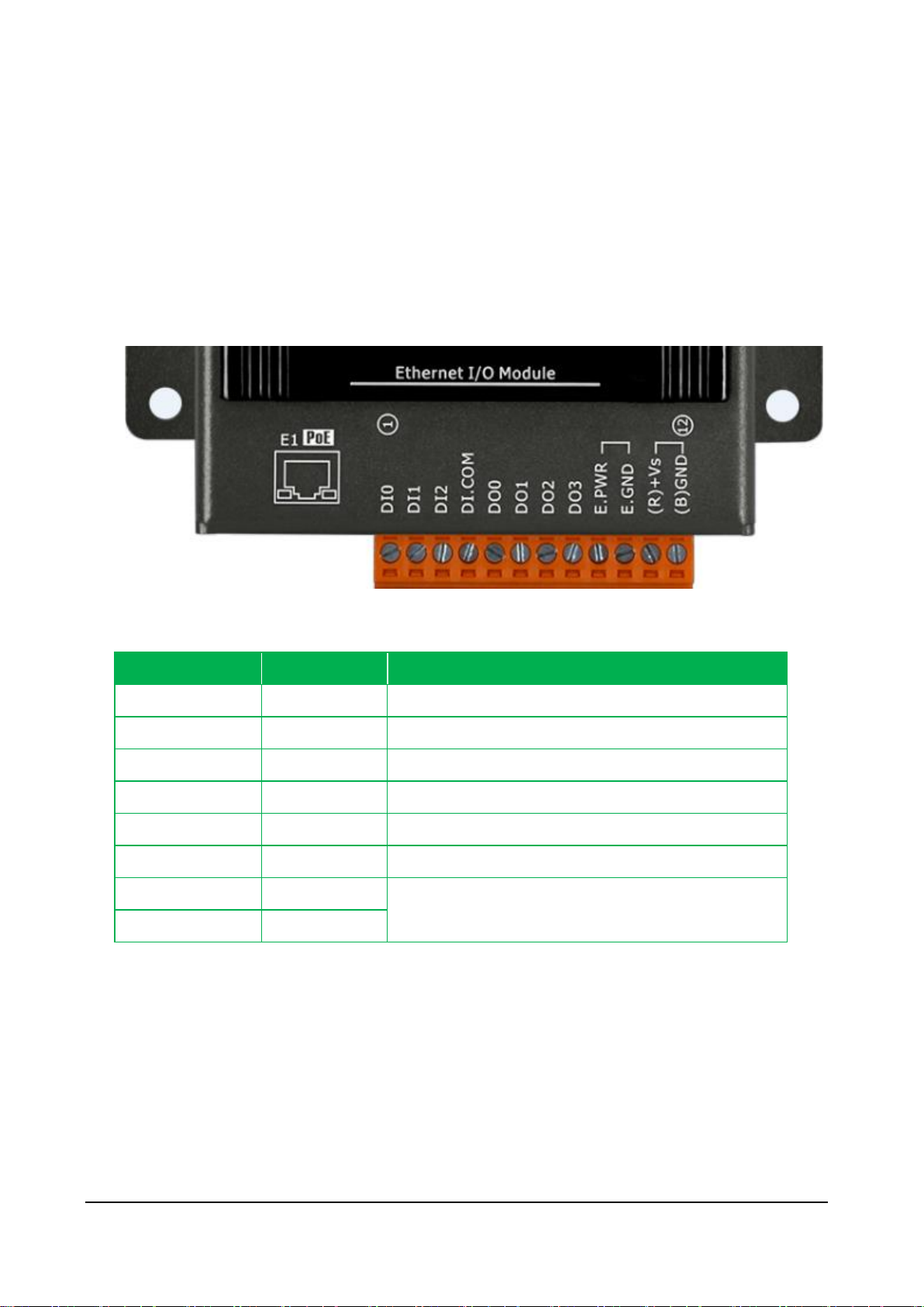
Signal
Direction
Description
DI0 ~ DI2
Input
Digital Input channels 0 to 3.
DI.COM
Common source
DO0 ~ DO3
Output
Digital Output channels 0 to 3.
DGND
-
Digital Ground.
E.PWR
External power for Digital Output
E.GND
External Ground for Digital Output
(R) +Vs
(R) +Vs
Power Input (+12 ~ +48 VDC)
(B) GND
(B) GND
JP1 Connector
The JP1 connector has 12 pins arranged in 1 row. For more detailed information regarding
the pin assignments of the J1 Connector, please refer to “1.2. Specification”
The pin assignments of the connector are as follows:
PET-7H24M Series User Manual, version 1.0.0 P.17
Page 18
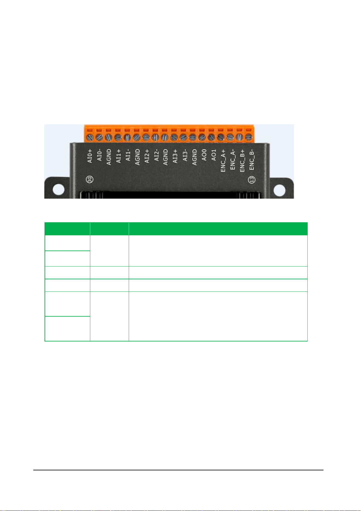
Signal
Direction
Description
AI0+ ~ AI3+
Input
Analog Input channels 0 to 3.
AI0- ~ AI3-
AGND
-
Analog Input Ground.
AO0 ~ AO1
Output
Analog Output channels 0 to 1.
ENC_A+、
ENC_B+
Input
Encoder input
ENC_A-
ENC_B-
JP2 Connector
The JP2 connector has 18 pins arranged in 1 row. For more detailed information regarding
the pin assignments of the J2 Connector, please refer to “1.2. Specification”
The pin assignments of the connector are as follows:
PET-7H24M Series User Manual, version 1.0.0 P.18
Page 19
Data Item
Factory Default Settings
IP
192.168.255.1
Gateway
192.168.0.1
Mask
255.255.0.0
DHCP
Disable
Factory Default Setting
Original factory calibration value
Factory Default Setting
A default user account consists of an account name “Admin” and a password “Admin”.
Factory Default Setting
Empty, there is no limit to allow any outgoing access.
Reset Button
The Reset button provides user with a quick
and easy way to resort the default setting.
Press the Reset button continuously for 5
seconds, and then release it. The device will
restore to factory default settings.
The table below lists the default settings after pressing reset button.
Network Settings
Gain/offset value of AI calibration
Account Management
Accessible IP Settings
PET-7H24M Series User Manual, version 1.0.0 P.19
Page 20
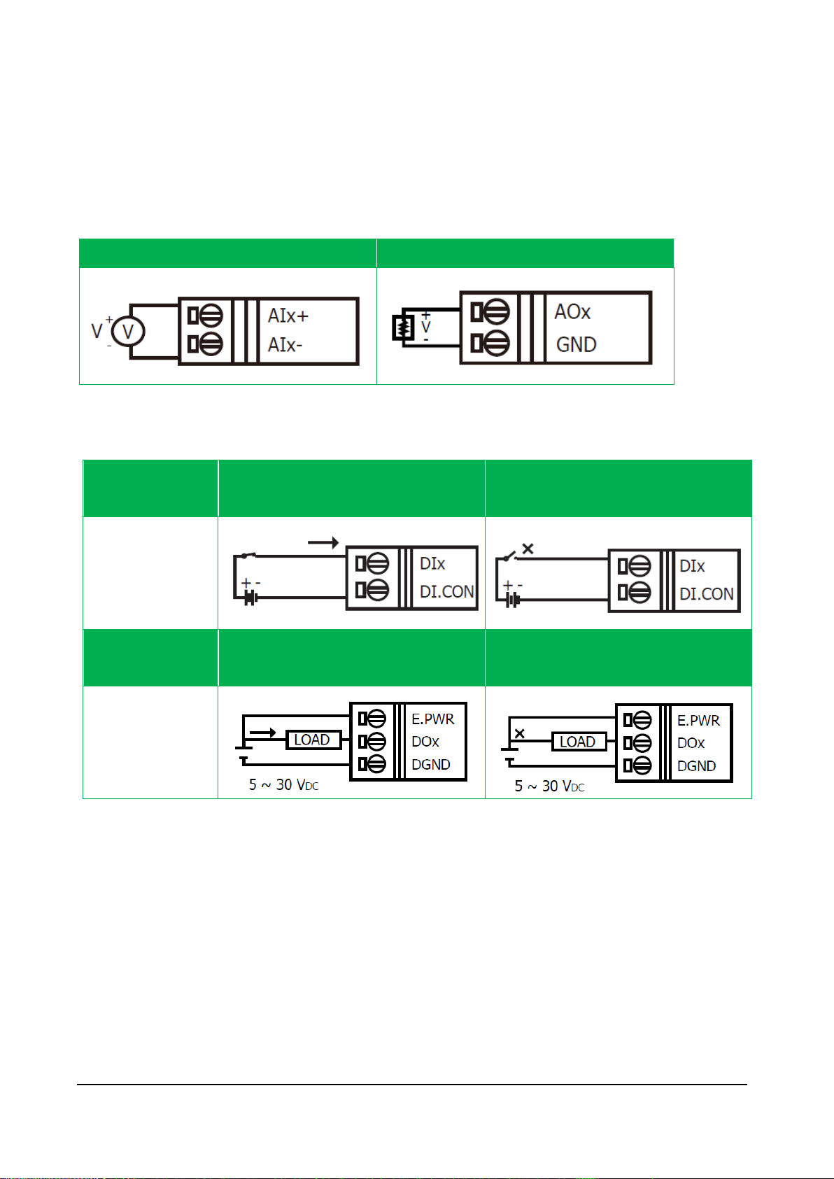
Analog Input (Voltage)
Analog Output (Voltage)
Digital
Input/Counter
ON State
Readback as 1
OFF State
Readback as 0
Wet Contact
(Sink)
Digital Output
ON State
Readback as 1
OFF State
Readback as 0
Open Collector
(Sink)
1.4. Wiring Diagram
The wiring diagram of the PET-7H24M is illustrated on the following figure.
PET-7H24M Series User Manual, version 1.0.0 P.20
Page 21
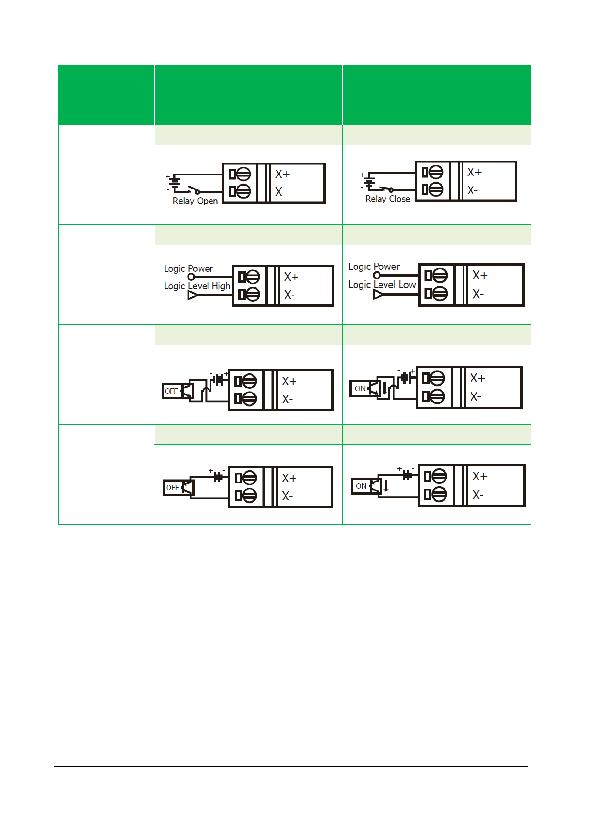
Encoder
Input/Output
Type
ON State
Readback as 0
OFF State
Readback as 1
Relay Contact
Relay ON
Relay OFF
TTL/CMOS Logic
Voltage > 3.5 V
Voltage > 0.8 V
NPN Output
Open Collector ON
Open Collector OFF
PNP Output
Open Collector ON
Open Collector OFF
PET-7H24M Series User Manual, version 1.0.0 P.21
Page 22
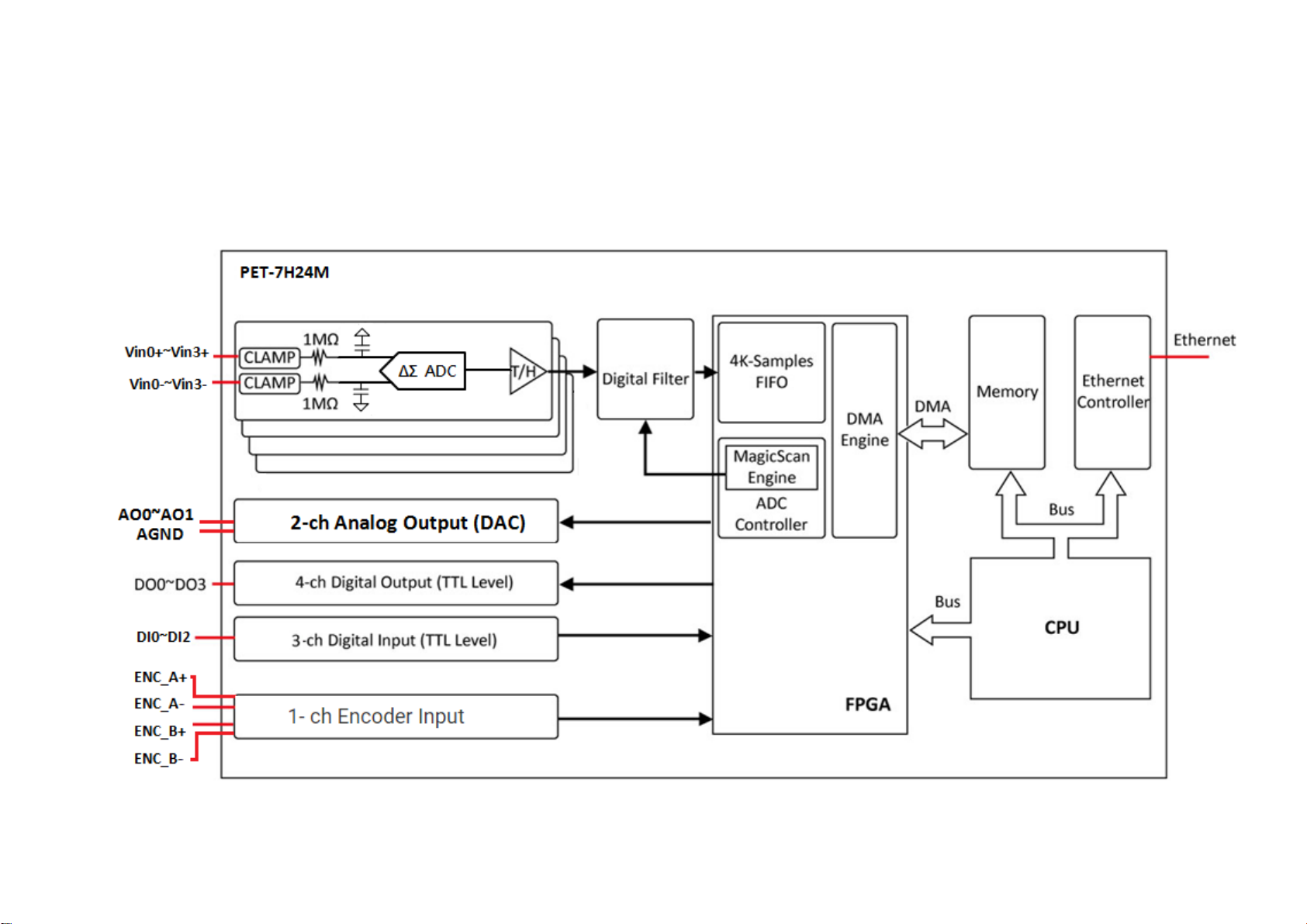
1.5. Block Diagram
PET-7H24M functions are illustrated in the block diagram shown here.
Page 23
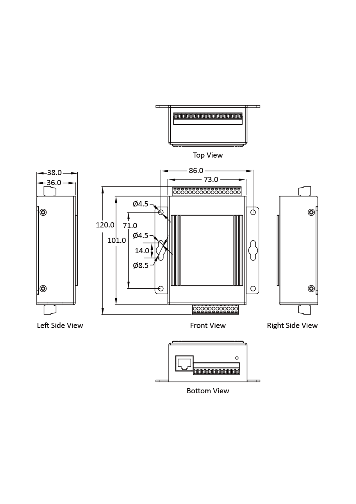
1.6. Dimension
The diagrams below provide the dimensions of the PET-7H24M to use in defining your enclosure
specifications. All dimensions are in millimeters.
Page 24
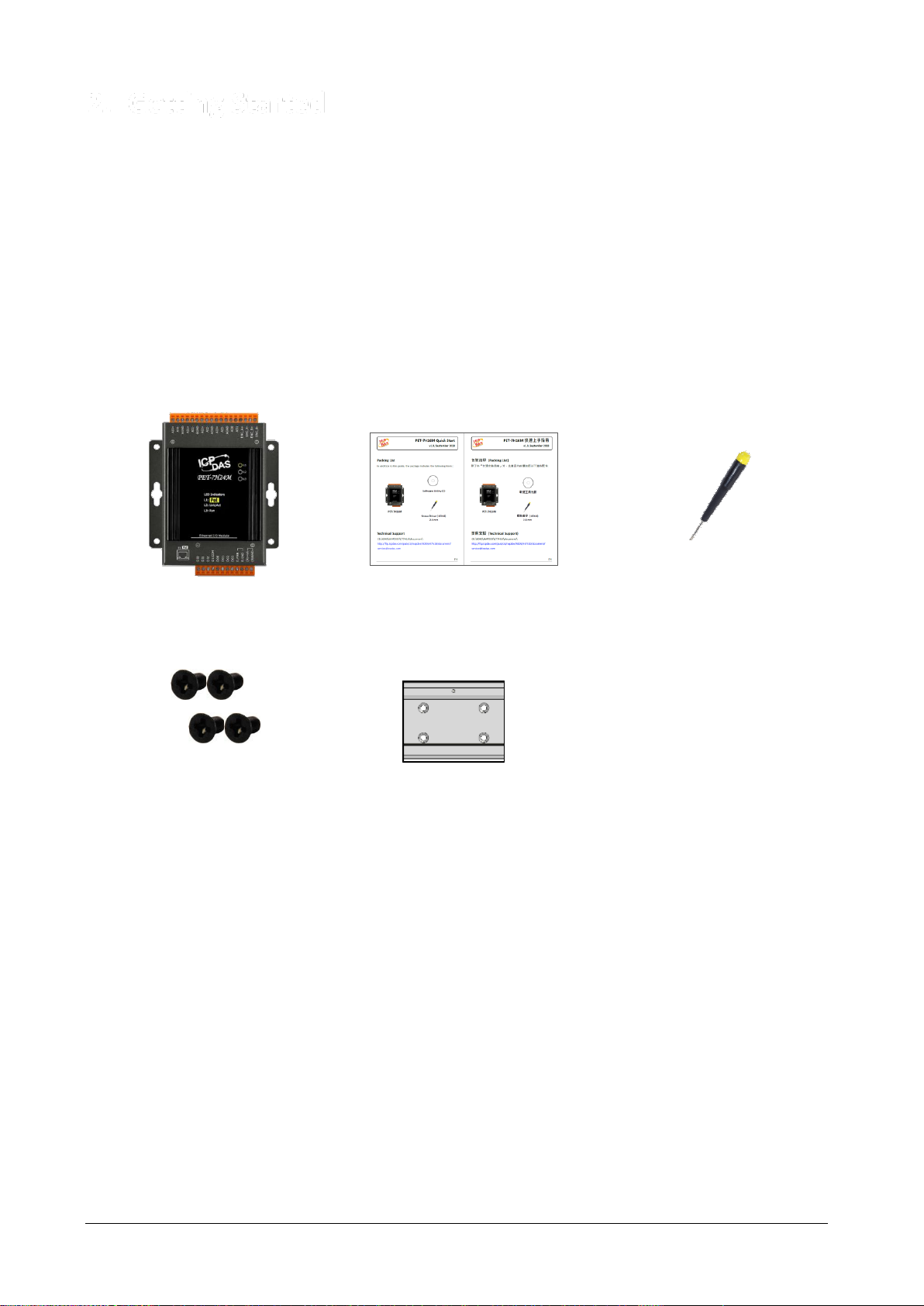
PET-7H24M
Quick Start Guide
2.4 mm Screw Driver
M3 x 6L Screw * 4
44 mm DIN-Rail clip
2. Getting Started
If you are a new user, begin with this chapter, it includes a guided tour that provides a basic
overview of installing, configuring and using the PET-7H24M.
Before starting any task, please check the package contents. If any of the following package
contents are missing or damaged, contact your dealer on distributor.
Before you work with the PET-7H24M, you should have a basic understanding of hardware
specification, such as the dimensions, the usable input-voltage range of the power supply, and the
type of communication interfaces.
For more information about the hardware details, please refer to “1.2. Specification”
For more information about the hardware dimensions, please refer to “1.6. Dimension”
PET-7H24M Series User Manual, version 1.0.0 P.24
Page 25
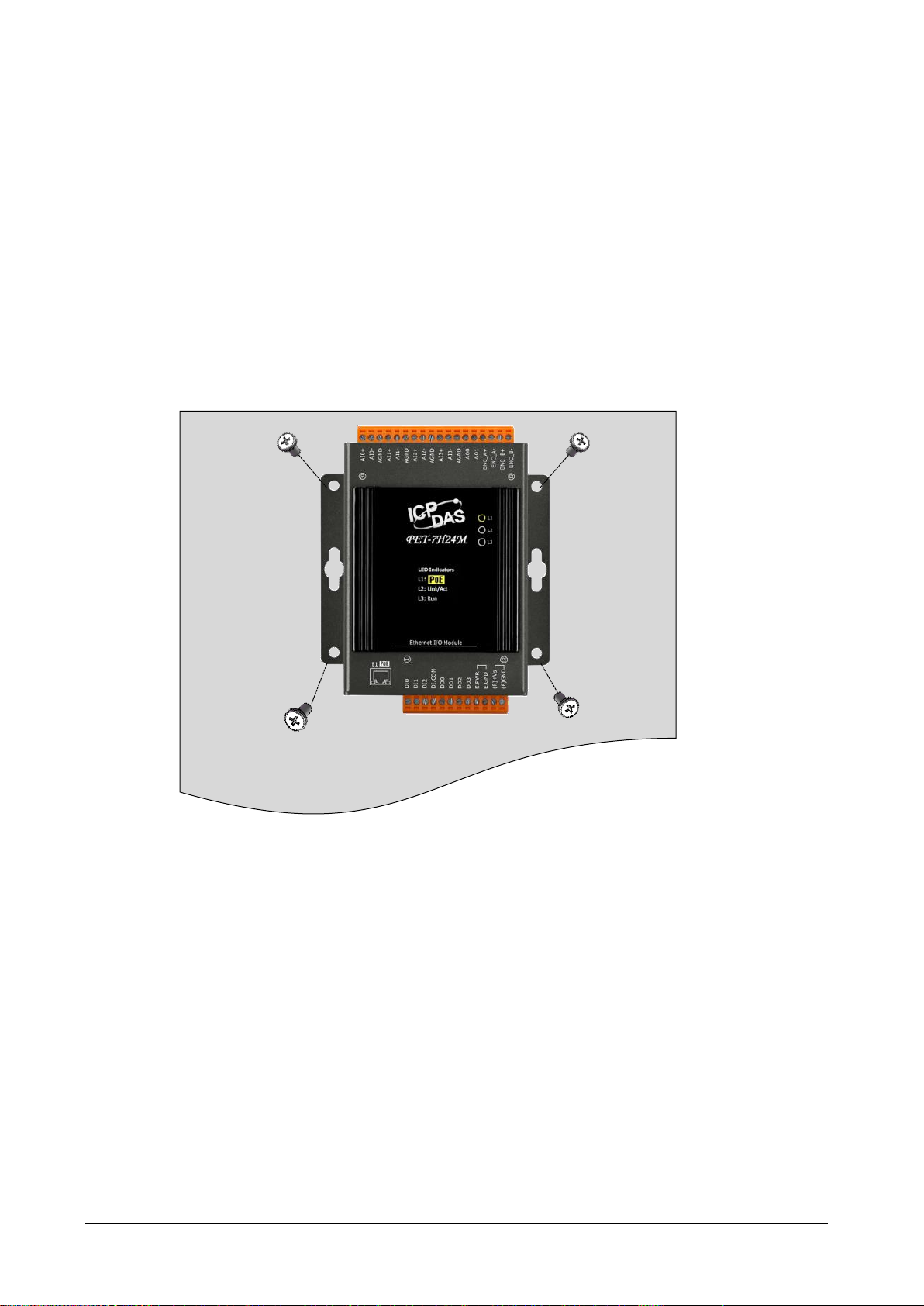
2.1. Mounting the Hardware
The PET-7H24M can be mounted either directly to a wall/panel.
Step 1: Use the included screws and a screw driver to attach the PET-7H24M to the wall/panel
Step 2: Fasten the screws securely
PET-7H24M Series User Manual, version 1.0.0 P.25
Page 26
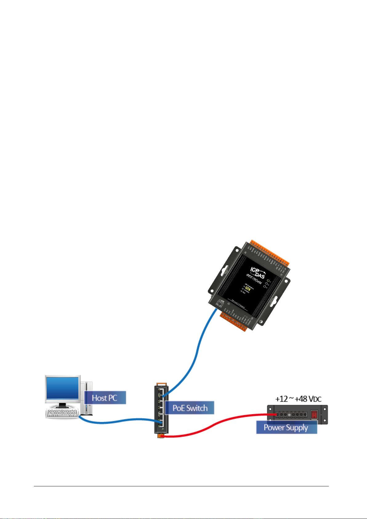
2.2. Deploying a Basic PET-7H24M System
Here is a simple application for using the PET-7H24M that is shown below.
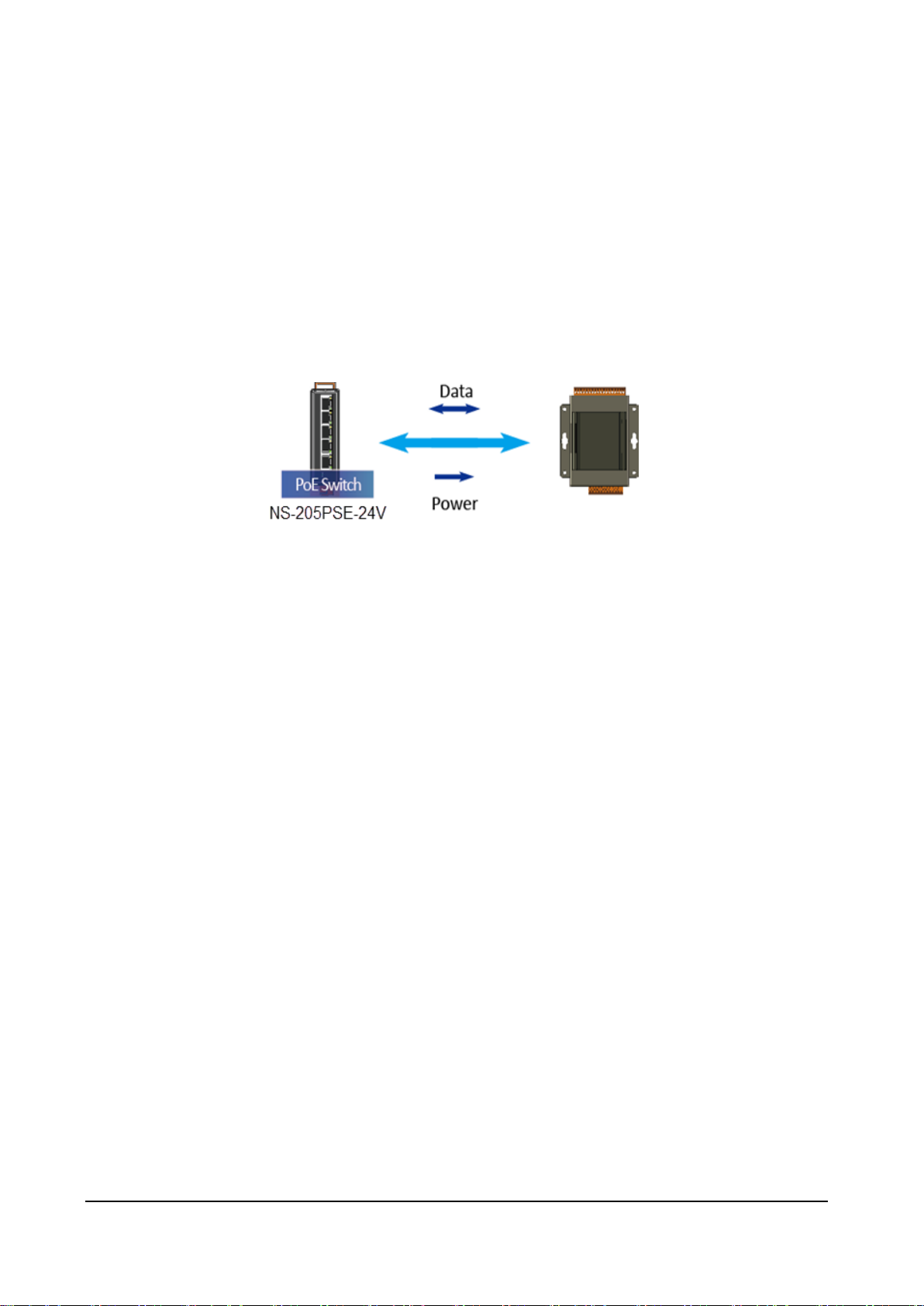
There are two ways for the PET-7H24M module getting the power. One is through Ethernet by a
PoE switch; the other is as usual through wiring by an external power. External power should
range from +12 VDC to 48 VDC. The reason we keep the second way is because it might be useful
if someday or somehow you have different applications. PET-7H24M module is equipped with a
LED, which indicates whether the power is supplied by a PoE switch.
PoE
i. Connect PC to the Ethernet port via the PoE switch.
ii. Connect the power supply to the PoE switch, which supplies power to the PET-7H24M.
PET-7H24M Series User Manual, version 1.0.0 P.26
Page 27

External Power supply
i. Connect PC to the Ethernet port via the Ethernet switch.
ii. Connect the power supply to the switch and PET-7H24M.
Tips & Warnings
Network: connections with fewer switches between the PC and the HSDAQ
device(s) can improve AI acquisition performance. It is recommended to connect
the PC and the HSDAQ device(s) to the same switch/hub.
PET-7H24M Series User Manual, version 1.0.0 P.27
Page 28

2.3. Installing the HSDAQ Utility
The HSDAQ Utility is a useful tool that provides a quick and easy way to update firmware,
configure Ethernet settings, and download files to PET-7H24M from PC.
Refer to chapter 4.2. HSDAQ Utility for more details.
Step1: Get the HSDAQ Utility tool
The HSDAQ Utility can be obtained from the following link:
http://www.icpdas.com/en/download/show.php?num=2327&model=PET-7H24M
Step 2: Follow the prompts to complete the installation
After the installation has been
completed, there will be a new
short-cut for HSDAQ Utility on the
desktop.
PET-7H24M Series User Manual, version 1.0.0 P.28
Page 29

Item
Default
IP Address
192.168.255.1
Subnet Mask
255.255.0.0
Gateway
192.168.0.1
2.4. Using HSDAQ Utility to Assign an IP address
The PET-7H24M is an Ethernet device, which comes with a default IP address, therefore, you must
first assign a new IP address to the PET-7H24M.
The factory default IP settings are as follows:
Step 1: Run the HSDAQ Utility
Double-click the HSDAQ Utility shortcut on your desktop.
PET-7H24M Series User Manual, version 1.0.0 P.29
Page 30

Step 2: Press choose “Search” from the “Tools” menu
After choosing Search from Tools menu, that will search all of the PET-7H24M modules on
your network.
Step 3: Choose the field “192.168.255.1” and then choose “IP setting” from the toolbar
Choose default value “192.168.255.1” for fields in the list and double-click.
PET-7H24M Series User Manual, version 1.0.0 P.30
Page 31

Step 4: Assign a new IP address and then choose “Set” button
You only can manually assign an IP address.
Step 5: Click “OK” button
When the setup is completed, click the "OK" button.
Step 6: Wait for PET-7H24M reboot
PET-7H24M Series User Manual, version 1.0.0 P.31
Page 32

Acquisition
Trigger
Continuous
N Sample
Software AD
20~60KHz
60 kHz ~ 128 KHz
Analog Input Trigger
-
20 Hz ~ 128 KHz
3. Operation
Once connected to the network, the PET-7H24M module can be remotely accessed and configured
through software from anywhere on the network and the sampling data only can be acquired by
software over Ethernet. So far, the device doesn’t operate as a stand-along data logger. The only
one connection at a time is allowed to acquire data from PET-7H24M.
There are two different data acquisition modes and several trigger modes of analog input
operation.
The following chart shows the acquisition and trigger modes and their operation frequency of
each combination.
Tips & Warnings
Maximum 30,000,000 records in N Sample Mode
125 sec (60 KHz), 62.5 sec (128 KHz) of 30,000,000 records in software AD
trigger.
PET-7H24M Series User Manual, version 1.0.0 P.32
Page 33

Ethernet
AI0
AI3
…
Software trigger
DMA
Internal Clock
CON1
PGA
Sampling
Hold
FIFO
Memory
ADC
3.1. Continuous Acquisition
Software AD Trigger 3.1.1.
In continuous acquisition and software AD trigger, Send a start command from PC over the
Ethernet to PET-7H24M to start the AD conversion. The analog input value is continuously
acquired and converted to digital data. The data accumulated to a network packet size returns to
the PC. The process of acquiring data is continuous until a stop command is sent over the
Ethernet.
The sample rate can range from 20 to 60K Hz on local networks. (Lower over the Internet or
wireless networks).
There are parameters below that need to be specified:
Sampling rate (20~60KHz)
Scan channels
The trigger mode is software AD trigger
PET-7H24M Series User Manual, version 1.0.0 P.33
Page 34

PET-7H24M Series User Manual, version 1.0.0 P.34
Page 35

3.2. N Sample Acquisition
Software AD Trigger 3.2.1.
In N sample acquisition and software AD trigger, Send a start command from PC over the Ethernet
to PET-7H24M to start the AD conversion. The analog input value is continuously acquired and
converted to digital data until the total number of samples reaches. Send a command to get the all
acquisition data over the Ethernet.
The sample rate can range from 20 Hz to 128K Hz.
There are some parameters that need to be specified:
Sampling rate
Scan channels
Sampling Count (Maximum 30,000,000 records)
The trigger mode sets to the software AD trigger.
PET-7H24M Series User Manual, version 1.0.0 P.35
Page 36

AI0
AI3
…
DMA
Internal Clock
CON1
PGA
Sampling
Hold
FIFO
Memory
ADC
Ethernet
Analog Input Trigger 3.2.2.
The analog input trigger is triggered when the input voltage signal is above or below a certain
voltage setting. In addition, the analog trigger can be used to detect the instantaneous change in a
continuous voltage signal. The user can specify the trigger voltage level range of the input signal.
Once the range is exceeded or the voltage level is entered, the data is triggered to start collecting
data.
There are some parameters that need to be specified:
Sampling rate (20~128KHz)
Scan channels
Sampling Count (Maximum 30,000,000 records)
Set the high or low level voltage value
Trigger mode set to analog input trigger
AI trigger
PET-7H24M Series User Manual, version 1.0.0 P.36
Page 37

PET-7H24M Series User Manual, version 1.0.0 P.37
Page 38

4. Tools and SDKs
PET-7H24M supports a number of external tools to aid in developing your applications
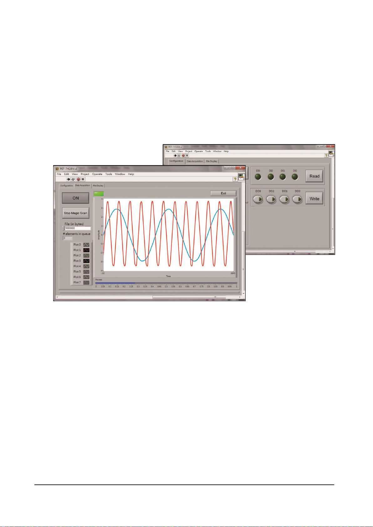
4.1. LabVIEW
LabVIEW is the best way to acquire, analyze, and present data. LabVIEW delivers a graphical
development environment that can be used to quickly build data acquisition quickly,
instrumentation and control systems, boosting productivity and saving development time. With
LabVIEW, it is possible to quickly create user interfaces that enable interactive control of software
systems. To specify your system functionality, simply assemble block diagram – a natural design
notation for scientists and engineers.
The document containing the detailed instructions for linking to the PET-7H24M using the Modbus
protocol is located on the shipped
http://www.icpdas.com/web/product/download/io_and_unit/ethernet/pet-7h16m/software/utili
ty/LabVIEW.zip
PET-7H24M Series User Manual, version 1.0.0 P.38
Page 39

4.2. HSDAQ Utility
HSDAQ Utility is used to graphically display and easily data logging for ET-7H24 module.
HSDAQ Utility tool as ET-7H24 Data Logger
ET-7H24 Data Logger provides a single ET-7H24 connect as Data Logger function.
1. When connect to ET-7H24, it will get the parameters of gain and offset for calibration, they
are used to calibrate the raw data from ET-7H24.
2. It also gets the configurations for sampling, set the new configurations for application then
start, it will begin to get the sampling data from ET-7H24 and save the data to files.
3. After finish sampling data or stop data logger, it can show the sampling result as plot view.
PET-7H24M Series User Manual, version 1.0.0 P.39
Page 40

System requirement
Minimum system requirements for HSDAQ Utility are given below:
266MHz 32-bit(x86) or 64-bit(x64) processor
64 MB of system memory
Support for Super VGA graphics
At least 20 MB of available space (Need more)
Microsoft Windows 2000 or later(32-bit or 64-bit Windows Operating System)
Operating system of Windows requirement
32-bit(x86) 64-bit(x64)
Microsoft Windows 2000 -
Microsoft Windows XP 32-bit Microsoft Windows XP 64-bit
Microsoft Windows 2003 32-bit Microsoft Windows 2003 64-bit
Microsoft Windows Vista 32-bit Microsoft Windows Vista 64-bit
Microsoft Windows 7 32-bit Microsoft Windows 7 64-bit
Microsoft Windows 2008 32-bit Microsoft Windows 2008 64-bit
Microsoft Windows 8 32-bit Microsoft Windows 8 64-bit
Microsoft Windows 2012 64-bit
PET-7H24M Series User Manual, version 1.0.0 P.40
Page 41

File
Description
HSDaq.dll
Used for VC programs
HSDaqNet.dll
Used for .Net programs
4.3. SDK API
This chapter provides a brief overview of ET-7H24 APIs that have been designed for ET-7H24.
ET-7H24 SDK library supports 32/64 bit Windows 2003/Vista/7/8/10.
Get the latest version of ET-7H24 SDK library at the location below.
The latest version of the installation package from the following link:
http://www.icpdas.com/en/download/show.php?num=2326&model=PET-7H24M
Before using HSDAQ.dll & HSDAQNet.dll, you must install HSDAQ_SDK_package.exe to use the dll
correctly. The program and SDK get the same path. Need to restart the computer after installation.
For installation steps, please refer to "ET-7H24 Standard API User Manual".
For full usage information regarding the description, prototype and the arguments of the functions,
please refer to the “ET-7H24 Standard API User Manual”
http://www.icpdas.com/web/product/download/io_and_unit/ethernet/pet-7h16m/document/m
anual/pet-7h16m_api_reference_manual_en.pdf
PET-7H24M Series User Manual, version 1.0.0 P.41
Page 42

HSDAQ.dll Functions
HSDAQNet.dll Functions
Description
HS_Device_Create
Sys.HS_Device_Create
Create a connection to the device and initialize the device. This
function is the driver entry.
HS_Device_Release
Sys.HS_Device_Release
Release the device from system.
HS_Reboot
Sys.Reboot
This function reboots the ET-7H24.
HS_GetFirmwareVersion
Sys.GetFirmwareVersion
Read the firmware version of ET-7H24
HS_GetSDKVersion
Sys.GetSDKVersion
This function retrieves the version number of the current HSDAQ.dll
Sys.GeHSDAQNetVersion
This function retrieves the version number of the current
HSDAQNet.dll
HS_ReadGainOffset
Config.HS_ReadGainOffset
Read the gain/offset values for application to calibrate each
channel’s analog data
HS_SetConfig
Config.HS_SetConfig
Set the configuration option for a device.
HS_SetConfigString
Config.HS_SetConfigString
Set the configuration option for a device with the string.
HS_GetConfig
Config.HS_GetConfig
Read the configuration option for a device.
HS_GetConfigString
Config.HS_GetConfigString
Read the configuration option for a device with the string.
HS_ReadAIALL
IO. ReadAIALL
Reads all the AI values of all channels in engineering-mode.
HS_ReadAI
IO. ReadAI
Reads the AI value of a channel in engineering-mode
HS_WriteAO
IO.WriteAO
Write the AO value
HS_WriteAOHEX
IO.WriteAOHEX
Write the AO HEX value
HS_ReadDIO
IO. ReadDIO
Reads the DI and DO values
HS_WriteDO
IO. WriteDO
Writes the DO value
The following API functions are used to access ET-7H24 modules.
Page 43

HS_WriteDOBit
IO. WriteDOBit
Writes a DO value to a channel
HS_GetEncoderMode
IO. HS_GetEncoderMode
Get the Encoder setting parameter from PET-7H24M
HS_SetEncoderMode
IO. HS_SetEncoderMode
Set the Encoder parameter for PET-7H24M
HS_ReadEncoder
IO. HS_ReadEncoder
Read the Encoder value
HS_ClearEncoder
IO. HS_ClearEncoder
Clear the Encoder value
HS_GetAIScanParam
HSIO.HS_GetAIScanParam
Get the AI scan parameter from PET-7H24M regarding of the
sampling rate, scan channels, pacer gain, trigger mode.
HS_SetAIScanParam
HSIO.HS_SetAIScanParam
Set the AI scan parameter for PET-7H24M regarding of the sampling
rate, scan channels, pacer gain, trigger mode.
HS_StartAIScan
HSIO.HS_StartAIScan
Start data acquisition. The data is stored in memory and transfer to
the data buffer on PC.
HS_StopAIScan
HSIO.HS_StopAIScan
Stop data acquisition.
HS_GetAIBuffer
HSIO.HS_GetAIBuffer
Get the floating-point value from data buffer on PC
HS_GetAIBufferHex
HS_GetAIBufferStatus
HSIO.HS_GetAIBufferHex
Get the binary data from data buffer on PC
HSIO.HS_GetAIBufferStatus
Get the status and data number from data buffer on PC.
HS_ClearAIBuffer
HSIO.HS_ClearAIBuffer
Clear the data buffer on PC
HS_GetTotalSamplingStatus
HSIO.HS_GetTotalSamplingStatus
Read the module status of ET-7H24 during data sampling
HS_TransmitDataCmd
HSIO.HS_TransmitDataCmd
Notify ET-7H24 module to send data to PC through TCP data port
HS_SetEventCallback
HSIO.HS_SetEventCallback
Bind the event condition to a user-defined callback function
HS_RemoveEventCallback
HSIO.HS_RemoveEventCallback
Disable the event condition and callback function.
PET-7H24M Series User Manual, version 1.0.0 P.43
Page 44

HS_StartLogger
DATALOG.HS_StartLogger
Start the data logging and save data to the specified folder on
storage disk of the host PC
HS_StartLoggerW
HS_StartLoggerW is a wide-character version of HS_StartLogger. The
specified folder can included wild-character.
HS_StopLogger
DATALOG.HS_StopLogger
Stop the data logging.
HS_GetAllLogFiles
DATALOG.HS_GetAllLogFiles
Search all log files in the specified folder with the specified file type
and return the total number of files
HS_LogFile_Open_byIndex
DATALOG.HS_LogFile_Open_byIndex
Open a data log file by the index number searched by HS_GetAllLogFiles
HS_LogFile_Open
DATALOG.HS_LogFile_Open
Open a data log file by the specified path and file name.
HS_LogFile_OpenW
HS_LogFile_OpenW is a wide-character version of HS_LogFile_Open. The
specified folder and file name can be included wild-character.
HS_LogFile_Close
DATALOG.HS_LogFile_Close
Closes a data log file opened by HS_LogFile_Open.
HS_GetLogFileInfo
HS_GetLogFile_AIScanConfigInfo
DATALOG.HS_GetLogFileInfo
Get the data log file information including the file version and file size.
DATALOG.HS_GetLogFile_AIScanConfigInfo
Get the data log file information regarding of the sampling rate, scan
channels, pacer gain and trigger mode.
HS_GetLogFile_GainOffset
DATALOG.HS_GetLogFile_GainOffset
Get the data log file information regarding of the gain/offset values for
each AI channel.
HS_GetLogFile_AIScanSampleInfo
DATALOG.HS_GetLogFile_AIScanSampleInfo
Get the total sampling counts and the starting time of first triggered
sampling data in the data log file
HS_GetLogFile_AIData
DATALOG.HS_GetLogFile_AIData
Reads AI input data from the text file
HS_GetLogFile_AIDataHex
DATALOG.HS_GetLogFile_AIDataHex
Read AI input data(Hex) from the binary file
PET-7H24M Series User Manual, version 1.0.0 P.44
Page 45

HS_GetLastError
ErrHandling.GetLastError
Retrieves the last-error code value.
HS_SetLastError
ErrHandling.SetLastError
Sets the last-error code.
HS_GetLastErrorMessage
ErrHandling.GetErrorMessage
Retrieves a message string.
HS_ClearLastError
ErrHandling.ClearLastError
Clears the last-error code.
PET-7H24M Series User Manual, version 1.0.0 P.45
Page 46

Visual C++ Samples
The ET-7H24 VC demo includes the following samples that demonstrate the use of the
ET-7H24 Standard APIs in a Visual C++ language environment. The following samples can be
found by downloading the latest version from ICP DAS web site.
For Visual C++ applications, these demo programs can be obtained from:
http://www.icpdas.com/web/product/download/io_and_unit/ethernet/pet-7h16m/software
/demo/VC.zip
C# Samples
The ET-7H24 C# demo includes the following samples that demonstrate the use of the
ET-7H24 Standard APIs in a C# language environment. The following samples can be found
by downloading the latest version from ICP DAS web site.
For C# applications, these demo programs can be obtained from:
http://www.icpdas.com/web/product/download/io_and_unit/ethernet/pet-7h16m/softwar
e/demo/C%23.zip
VB.net Samples
The ET-7H24 VB.net demo includes the following samples that demonstrate the use of the
ET-7H24 Standard APIs in a VB.net language environment. The following samples can be
found by downloading the latest version from ICP DAS web site.
For C# applications, these demo programs can be obtained from:
http://www.icpdas.com/web/product/download/io_and_unit/ethernet/pet-7h16m/softwar
e/demo/VB.Net.zip
Page 47

Item
Default
User name
Admin
Password
Admin
5. Web Applications
The PET-7H24M contains an advanced web configuration system that provides users with access
PET-7H24M applications through a standard web browser.
Note: The web page function is only suitable for configuration settings. Do not enable this TCP
communication when the module is acquitting the data via Ethernet.
Logging in to the PET-7H24M Web site
You can log in to the PET-7H24M web site from any computer that has Internet access.
Step 1 : Open a browser
In several browsers, Mozilla Firefox and Internet Explorer are both reliable and popular
Internet browsers.
Step 2: Type the URL address of the PET-7H24M
If you haven’t changed the default IP address of the PET-7H24M, please refer section “2.4.
Using HSDAQ Utility to Assign an IP address” to configure it.
Step 3: Fill out the User name and Password
After entering the IP address, the login dialog box will appear and prompt you to enter your
username and password.
The factory default user name and
password are as follows:
PET-7H24M Series User Manual, version 1.0.0 P.47
Page 48

Step 4: Welcome to PET-7H24M web site
After logging into the PET-7H24M web site, the welcome page will appear.
This site serves several functions. You can easily access
these functions through the menu on the left side.
The Overview of the Main menu provides a brief
introduction and explanation of this site.
PET-7H24M Series User Manual, version 1.0.0 P.48
Page 49

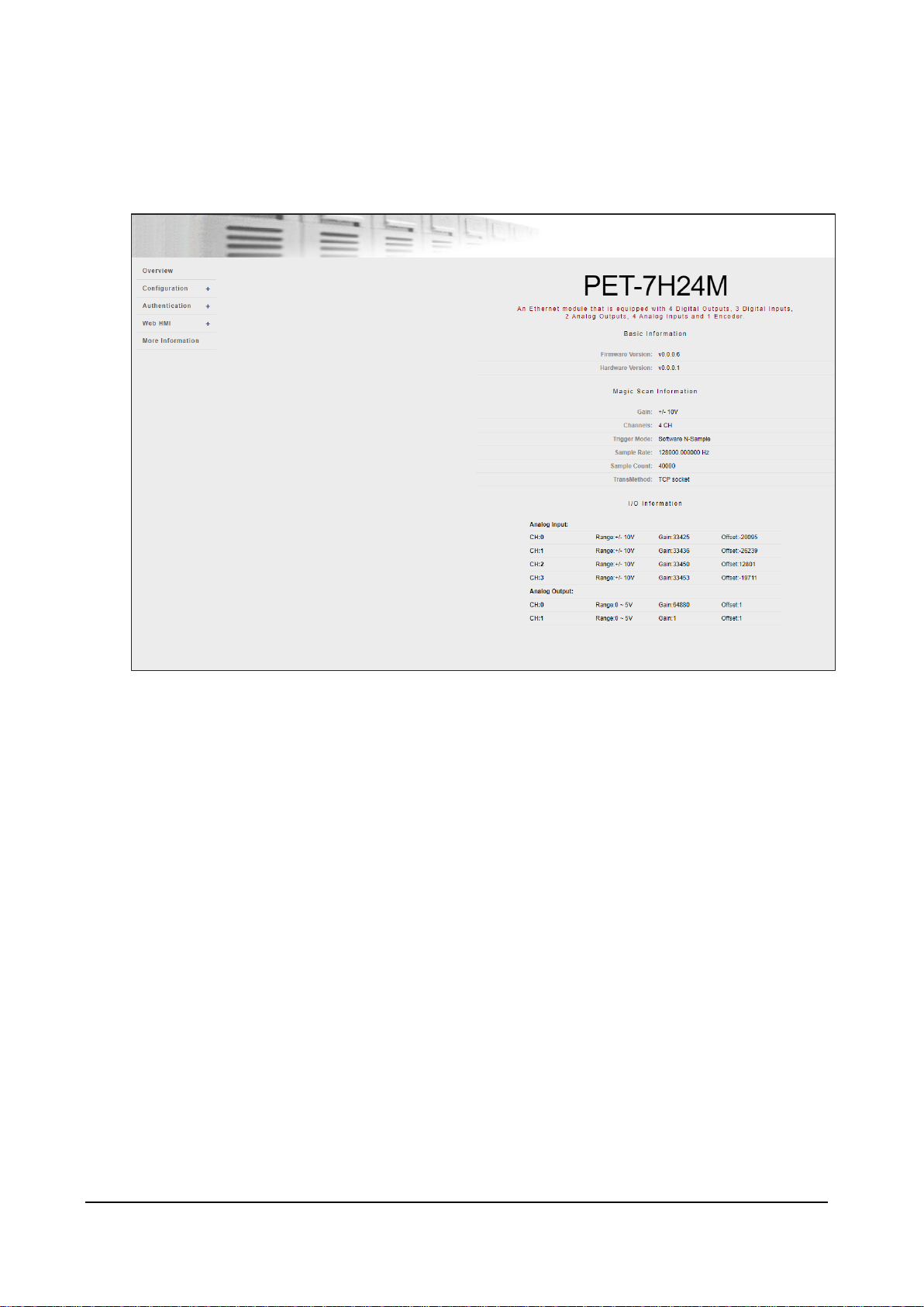
5.1. Overview
The Overview links to the welcome page that provides functions to monitor necessary system
information of PET-7016M. The information is the most important note of version control for
upgrading system.
This page provides basic information about the PET-7H24M.
Firmware Ver: Current firmware version
Hardware Version:Current hardmware version
Gain: Current input type
Channels: Current trigger channels
Trigger mode: Current trigger mode
Sample Rate: Current sample rate
TransMethod: Current transfer method
Sample Count: Current sample count
PET-7H24M Series User Manual, version 1.0.0 P.49
Page 50

5.2. Configuration
The Configuration menu consists of the following menu:
Network Settings: This menu links to the Network
Settings page that allows you to access the IP
settings.
Basic Settings: This menu links to the Basic Settings
page that allows you to configure the basic
information of this site.
Module I/O Settings: This menu links to the
Common Functions page that allows you to
configure the settings of the Modbus
PET-7H24M Series User Manual, version 1.0.0 P.50
Page 51

1
2
3
Network Settings 5.2.1.
The Network Settings page provides functions to configure either DHCP (Roaming) or manually
configured (Static) network settings.
Manually Configured Network Settings
1. Disable the DHCP
2. Assign an IP address
3. Click SUBMIT to finished configuring the network settings
PET-7H24M Series User Manual, version 1.0.0 P.51
Page 52

Basic Settings 5.2.2.
The Basic Settings page provides the following functions:
Configure the module information
Configure the web site information
Reset all settings to default
PET-7H24M Series User Manual, version 1.0.0 P.52
Page 53

1
2
5.2.2.1. Configuring the Module Information
The module information includes the following data items:
● Module Name: The name of the module that can be modified. It has an initial value depending
on the name of the module.
● Module Information: The module information indicates the name of the alias that is used to
identify the module.
To configure the module information
1. Enter the Module information
2. Click SUBMIT to finish configuring the module information
PET-7H24M Series User Manual, version 1.0.0 P.53
Page 54

Page Header Information (First line)
Page Header Information (Second line)
5.2.2.2. Configuring the Web site Information
The module information includes the following data items:
● Page Header Information (First line) and Page Header Information (Second line): The title of
the website that can be modified; you can view the title information in the top-left corner. The
title information can be determined as follows:
● Web Server TCP Port: A port number of the TCP/IP port. By default, TCP/IP uses port 80.
PET-7H24M Series User Manual, version 1.0.0 P.54
Page 55

1
2
To configure the web site information
1. Enter the web site information
2. Click Submit to finish configuring the module information
PET-7H24M Series User Manual, version 1.0.0 P.55
Page 56

2
1
5.2.2.3. Resetting All Settings to the Factory Default
According to the menu selection of this web, the reset function can be divided into the following
categories. You can use this function to reset the settings to their factory default.
Configuration
Authentication
All
To reset the settings to their factory default
1. Enable the reset selection
2. Click SUBMIT to finish resetting the settings to their factory default
PET-7H24M Series User Manual, version 1.0.0 P.56
Page 57

Data Item
Factory Default Settings
IP
192.168.255.1
Gateway
192.168.0.1
Mask
255.255.0.0
DHCP
Disable
Data Item
Factory Default Setting
Module Name
Depending on the module name
Module Information
Empty
Top page Information (First line)
ICP DAS
Top page Information (Second line)
http://www.icpdas.com
More Information URL
http://www.icpdas.com/products/Remote_I
O/et-7000/et-7000_introduction.htm
Web Server TCP Port
80
Factory Default Setting
A default user account consists of an account name “Admin” and a password “Admin”.
Factory Default Setting
Empty, there is no limit to allow any outgoing access.
Factory Default Settings for Configuration Menu
The table below lists the factory default settings of the configuration menu.
Network Settings
Basic Settings
Factory Default Settings for Authentication Menu
The table below lists the factory default settings of the Authentication menu.
Account Management
Accessible IP Settings
PET-7H24M Series User Manual, version 1.0.0 P.57
Page 58

5.3. Authentication
The Authentication menu consists of the following menu:
Account Management: This menu links to the
Privilege management page that allows you to
manage the user accounts and their privileges.
Accessible IP Settings: This menu links to the IP filter
Settings page that allow you to control access to the
web site
PET-7H24M Series User Manual, version 1.0.0 P.58
Page 59

Account Management 5.3.1.
The Basic Settings page provides the following functions:
Configure the user accounts
Load the factory default user account
PET-7H24M Series User Manual, version 1.0.0 P.59
Page 60

5.3.1.1. Configuring the user accounts
The PET-7H24M web site supports up to 5 user accounts.
A built-in administrator account
The built-in Administrator is basically a setup and disaster recovery account that can be
deleted. You can change the administrator account’s password.
Four user-defined accounts
Each user account consists of
An account name: Specifies the name of This can be your name or another alias
A password: The system will ask you to type this in twice to ensure it is correct.
The authority: that determines what operations the user is allowed to perform.
The authority has the following roles to determine what operations the user is allowed to perform.
Admin: Enables access to all PET-7H24M website features, functions, and commands.
User: Enables limited access to PET-7H24M website features, functions, and commands. In
general, operators cannot change configuration settings.
PET-7H24M Series User Manual, version 1.0.0 P.60
Page 61

1
2
To Create an User Account
When you create user accounts, you can Enable or Disable user accounts.
1. Enter the user account information, and then select the enable checkbox
2. Click SUBMIT to finish configuring the user accounts
PET-7H24M Series User Manual, version 1.0.0 P.61
Page 62

5.3.1.2. Loading the factory default user accounts
The PET-7H24M has a built-in administrator account named Admin that is created when it is
installed by default. The default account cannot be deleted.
Click RESET SETTINGS to configure the user account to the factory default settings.
PET-7H24M Series User Manual, version 1.0.0 P.62
Page 63

Accessible IP Settings 5.3.2.
The IP filter Settings page provides the following functions:
Configure IP filtering
PET-7H24M Series User Manual, version 1.0.0 P.63
Page 64

To Configure the IP filter
The PET-7H24M with an IP filter that enables you to restrict or grant user access based an
IP filter list you create.
The filter can be enabled or disable by selecting the Enable the IP filter table checkbox
Tips & Warnings
By default, there is no limit to allow any outgoing access.
PET-7H24M Series User Manual, version 1.0.0 P.64
Page 65

1
2
3
4
Here we provide two basic methods for configuring the IP filter.
Method 1 : Allows access from a single IP address
1. Select the Enable the IP filter table
2. Enter the same IP address in the From (IP Address) and To (IP Address)
3. Select the Active the rule checkbox
4. Click SUBMIT to finish configuring the list of IP filter
PET-7H24M Series User Manual, version 1.0.0 P.65
Page 66

1
2
3
4
Method 2: Allow access from a group of IP addresses
1. Select the Enable the IP filter table
2. Enter a range of IP addresses in the From (IP Address) and To (IP Address)
3. Select the Active the rule checkbox
4. Click SUBMIT to finish configuring the IP filter list
PET-7H24M Series User Manual, version 1.0.0 P.66
Page 67

5.4. Web HMI
The Web HMI menu consists of the following menu:
Web HMI: This menu links to the I/O monitor page
that allows you to monitor and control the I/O status
on PET-7H24M module remotely.
By default, this page displays summary information about
I/O channels that are classified according to the module
type.
PET-7H24M Series User Manual, version 1.0.0 P.67
Page 68

6. Modbus Applications
The PET-7H24M is a Modbus device that allows you to access terminals data via Ethernet and
communicates using a master-slave technique in which only one device (the master) can initiate
transactions (called queries). The other devices (slaves) respond by supplying the requested data
to the master, or by taking the action requested in the query.
PET-7H24M Series User Manual, version 1.0.0 P.68
Page 69

Register Map
Modbus devices usually include a Register Map. Modbus functions operate on register map
registers to monitor, configure, and control module I/O. The users should refer to the register map
for the PET-7H24M to gain a better understanding of its operation.
PET-7H24M Series User Manual, version 1.0.0 P.69
Page 70

Begin
address
Points
Description
Registers
per Point
Range
Access
Type
0
4
Digital Out
1
0 = off
1 = on
R/W
34
1
The data order of long value
to Modbus register
1
0: low byte, high byte
1: high byte, low byte
R/W
36
1
Reset the I/O settings to the
factory default state
1
1: Reset
W (Pulse)
37
1
Reset the web settings to
the factory default state
1
1: Reset
W (Pulse)
112
1
Reboot the module
1
1: Reboot
W (Pulse)
Begin
address
Points
Description
Registers
per Point
Range
Access
Type
0
4
Digital input value
1
0 = off
1 = on
R
Begin
address
Points
Description
Registers
per Point
Range
Access
Type
0
8
Analog Input
word
-32768 ~ +32767
R
16
8
Use Channel Gain Value
word
0 ~ 65535
R
32
8
Use Channel Offset Value
word
-32768 ~ +32767
R
80
1
Number of the DI channel
word
0 ~ 65535
R
81
1
Number of the DO channel
word
0 ~ 65535
R
82
1
Number of the AI channel
word
0 ~ 65535
R
90
1
OS image version
word
0 ~ 65535
R
91
1
Firmware version
word
0 ~ 65535
R
92
1
ET7H24 Library version
word
0 ~ 65535
R
94
1
TCP library version
word
0 ~ 65535
R
95
1
Web server library version
word
0 ~ 65535
R
100
1
Read module name
word
0 ~ 65535
R
0xxxx address table
1xxxx address table
3xxxx address table
PET-7H24M Series User Manual, version 1.0.0 P.70
Page 71

Begin
address
Points
Description
Registers
per Point
Range
Access
Type
32
1
Set AI type
word
0: +/- 5V
1: +/- 10V
R/W/E
33
1
Scan Channel Count
word
1 ~ 8
R/W
34
1
Trigger Type
word
0: Software start
1: External Trigger
2: Post-Trigger
3: Pre-Trigger
…
R/W/E
35
2
Sample Rate
word
R/W/E
37
2
Target Count
word
R/W/E
50
1
Read the boot count of the
module
word
R/W/E
60
1
The factory default value is 0
when the settings are set to
the factory default values
word
0 ~ 65535
R/W/E
4xxxx address table
PET-7H24M Series User Manual, version 1.0.0 P.71
Page 72

7. Updates
The firmware is stored in flash memory and can be updated to fix functionality issues or add
additional features, so we advise you to periodically check the ICP DAS web site for the latest
updates.
Step 1: Get the latest version of the firmware and the autoexec.bat file
The latest version of the PET-7H24M firmware and autoexec.bat file can be obtained from:
http://www.icpdas.com/en/download/show.php?num=2941&model=PET-7H24M
Step 2: Run the HSDAQ Utility
Double-click the HSDAQ Utility shortcut on your desktop.
PET-7H24M Series User Manual, version 1.0.0 P.72
Page 73

Step 3: Establish a connection to PET-7H24M
Click “Connect” button
Step 4: Choose “Erase Disk” from the “Command” menu
After establishing a connection, then choose upload Firmware from Tools menu.
Then confirm the IP of PET-7H24M, then click “…” button.
PET-7H24M Series User Manual, version 1.0.0 P.73
Page 74

Step 5: Choose the ET7H24_VXXXX.hex to upload
Select ET7H24_VXXXX.hex to upload, then click "Open File" and then click "Upload".
Step 6: End of upload
After uploading the file, the progress bar will be as shown below..
Tips & Warnings
You have to reboot the PET-7H24M after uploading the firmware.
PET-7H24M Series User Manual, version 1.0.0 P.74
Page 75

8. Calibration
When shipped from the factory, PET-7H24M is already fully calibrated, including the calibration
coefficients that are stored in the onboard EEPROM. For a more precise application of voltages in
the field, the procedure described below provides a method that allows the board installed in a
specific system to be calibrated so that the correct voltages can be achieved for the field
connection. This calibration allows the effects of voltage drops caused by IR loss in the cable
and/or the connector to be eliminated.
At first the user has to prepare the equipment for calibration
Precise multi-meter (The more precise meter is better)
Stable power supply
The calibration procedure will be described in detail in the following.
Connect the AI channels to the meter and power supply, as shown below:
PET-7H24M Series User Manual, version 1.0.0 P.75
Page 76

Step 1: Entering the IP and Port, and click Connect
After the connection is successful, the firmware version will be read back.
PET-7H24M Series User Manual, version 1.0.0 P.76
Page 77

Step 2:Output voltage 4.8V to ch0 ~ ch3 and the meter, and select +/-5V in Gain combo box.
Enter the value reading from the meter in Meter 1 textbox (the following example is
4.7990)
Tips & Warnings
The range of output voltage is 5V~0V and it’s better to output voltage value
near to 5V.
PET-7H24M Series User Manual, version 1.0.0 P.77
Page 78

Step 3: Click Point_1 button and get the raw data of each channel as following
Step 4:Output a voltage, -4.8V to ch0 ~ ch3 and the meter, enter the value reading from meter
in Meter 2 textbox (the following example is -4.7916)
PET-7H24M Series User Manual, version 1.0.0 P.78
Page 79

Step 5: Click Point_2 button and get the raw data of each channel as following(And write the
corrected value into EEPROM)
Step 6: Select +/- 10V in Gain combo box
Step 7: Repeat the Step2 ~ Step5, and the upper limit voltage outputs 9.8V in Step 2 and the
lower limit voltage outputs -9.8V in Step 5
The calculated Gain Offset will be stored in the EEPROM. After pressing "point_1" and then
pressing "point_2", the calibration is completed
Step 8: After completing the calibration, click on ShowGainOffset button to read Gain and Offset
value
PET-7H24M Series User Manual, version 1.0.0 P.79
Page 80

Address
Function Code
Data
Checksum
1 byte
1 byte
0 to 252 bytes
2 bytes
Appendix A. What is Modbus TCP/IP?
Modbus is a communication protocol developed by Modicon in 1979.
Different versions of Modbus used today include Modbus RTU (based on serial communication like
RS485 and RS232), Modbus ASCII and Modbus TCP, which is the Modbus RTU protocol embedded
into TCP packets.
Modbus TCP is an Internet protocol. The protocol embeds a Modbus frame into a TCP frame so
that a connection oriented approach is obtained thereby making it reliable. The master query’s the
slave and the slave responds with the reply. The protocol is open and hence highly scalable.
Modbus Message Structure
Modbus devices communicate using a master-slave (client-server) technique in which only one
device (the master/client) can initiate transactions (called queries). The other devices
(slaves/servers) respond by supplying the requested data to the master, or by taking the action
requested in the query.
A master’s query will consist of a slave address (or broadcast address), a function code defining
the requested action, any required data, and an error checking field. A slave’s response consists of
fields confirming the action taken, any data to be returned, and an error checking field.
Address specifies the address of the receiver.
Function Code specifies the message type.
Data is the data block.
Checksum specifies the numerical check value for testing the validity of the protocol.
PET-7H24M Series User Manual, version 1.0.0 P.80
Page 81

Reference
Description
0xxxx
Read/Write Discrete Outputs or Coils. A 0x reference address is used
to device output data to a digital output channel.
1xxxx
Read Discrete Inputs. The ON/OFF status of a 1x reference address is
controlled by the corresponding digital input channel.
3xxxx
Read Input Registers. A reference register contains a 16-bit number
received from an external source --- e.g. an analog signal.
4xxxx
Read/Write Output or Holding Registers. A 4x register is used to store
16-bits of numerical dada (binary or decimal), or to send the data from
the CPU to an output channel.
Code
Function
Reference
01 (01H)
Read Coils (Output) Status
0xxxx
02 (02H)
Read Input Status
1xxxx
03 (03H)
Read Holding Registers
4xxxx
04 (04H)
Read Input Registers
3xxxx
05 (05H)
Force Single Coil (Output)
0xxxx
06 (06H)
Preset Single Register
4xxxx
15 (0FH)
Force Multiple Coils (Outputs)
0xxxx
16 (10H)
Preset multiple Registers
4xxxx
A.1. Address
The first byte of information in the message structure of Modbus is the receiver’s address. The
valid addresses are in the range of 0 to 247. Addresses from 1 to 247 are given to individual
Modbus devices and 0 is used for broadcast.
A.2. Function Codes
The second byte in the frame structure is the function code. The function code describes what the
slave is required to do. Valid function codes are between 1 and 255. The slave uses the same
function code as the request to answer it. Only when error occurs in the system, the highest bit of
the function code will be made ‘1’. Hence the master will know if the message has been
transmitted correctly or not.
PET-7H24M Series User Manual, version 1.0.0 P.81
Page 82

A.3. Data Field
The data field consists of messages sent between master and slave. The messages contain
additional information about the action to be taken by the slave or any information requested by
the slave. When the slave does not require this information the data field can be nonexistent.
A.4. Error Check
The error check performed in Modbus/RTU is Cyclic Redundancy Check (CRC). Both the
transmitting device and the receiver compute CRC. Two bytes are used for this purpose and
generally one bit errors are detected by this method.
PET-7H24M Series User Manual, version 1.0.0 P.82
Page 83

Type Code
Input Range
Data Format
+F.S
-F.S
02
-10 to +10V
Engineering Unit
+10000
-10000
2’s comp HEX
7FFF
8000
01
-5 to +5V
Engineering Unit
+5000
-5000
2’s comp HEX
7FFF
8000
Appendix B. Analog Input Type and Data Format Table
PET-7H24M Series User Manual, version 1.0.0 P.83
Page 84

Symptom/Problem
Possible cause
Solution
The Run LED doesn’t light
Internal power has failed
Return the module for repair.
The Run LED indicator is ON
(light), but not flashing.
The module has possibly
crashed.
Reboot the module
Cannot communicate via the
Ethernet port, but the
PET-7H24M is still operating.
The IP/Mask/Gateway
address isn’t within the IP
address range of the LAN.
Change the IP/Mask/Gateway
address to match the LAN, or
ask the MIS administrator for
assistance.
The IP address has
restricted by the IP filter
settings
Check the IP filter setting using
the Web configuration.
There are more than 30
TCP/IP connections.
Reboot the module.
Able to explore the web page
through port 80 using a web
browser, but Modbus/TCP
program cannot access the
module through port 502.
Port 502 has been
restricted by the firewall.
Consult your MIS administrator
for assistance.
Modbus/TCP program can
access the module through
port 502, but Web browser
cannot explore the web page
through port 80 using a web
browser.
The Port 502 has restricted
by the firewall.
Consult your MIS administrator
for assistance.
The Web Configuration
function has been disabled.
(Shown on the Basic
Settings page)
Enable the Web Configuration
function using either the SMMI
or the console.
The Web server TCP port
has been changed from
port 80 (Shown on the Basic
Settings page)
Change the TCP port to 80 or
reconnect the PET-7H24M using
the specific TCP port.
Appendix C. Troubleshooting
A number of common problems are easy to diagnose and fix if you know the cause.
PET-7H24M Series User Manual, version 1.0.0 P.84
Page 85

Revision
Date
Description
1.0.0
August 2020
Initial issue
Appendix D. Revision History
This chapter provides revision history information to this document.
The table below shows the revision history.
PET-7H24M Series User Manual, version 1.0.0 P.85
 Loading...