


Industrial Computer Products
Data Acquisition Systems
ET-7X00/PET-7X00 Series
User Manual
Vers i o n 1 . 1.2, February 2014
ET-7000/ET-7200 Series
(Ethernet I/O)
PET-7000/PET-7200 Series
(PoE I/O)

ET-7X00/PET-7X00 User Manual, version 1.1.2 I
Copyright © 2014 ICP DAS CO., LTD. All Rights Reserved. E-mail: service@icpdas.com
Warranty
All products manufactured by ICP DAS are under warranty regarding
defective materials for a period of one year, beginning from the date of
delivery to the original purchaser.
Warning
ICP DAS assumes no liability for any damage resulting from the use of this
product. ICP DAS reserves the right to change this manual at any time
without notice. The information furnished by ICP DAS is believed to be
accurate and reliable. However, no responsibility is assumed by ICP DAS for
its use, nor for any infringements of patents or other rights of third parties
resulting from its use.
Copyright
Copyright © 2014 by ICP DAS CO., LTD. All rights are reserved.
Trademarks
Names are used for identification purpose only and may be registered
trademarks of their respective companies.
Contact US
If you have any problems, please feel free to contact us.
You can count on us for a quick response.
Email: service@icpdas.com

ET-7X00/PET-7X00 User Manual, version 1.1.2 II
Copyright © 2014 ICP DAS CO., LTD. All Rights Reserved. E-mail: service@icpdas.com
Table of Contents
1. Introduction ............................................................................................ 1
1.1. Features ............................................................................................................. 3
1.2. Overview ............................................................................................................ 6
1.3. Dimensions ...................................................................................................... 10
1.4. Companion CD ................................................................................................. 12
2. Getting Started ...................................................................................... 13
2.1. Mounting the ET-7X00/PET-7X00 .................................................................... 14
2.2. Configuring the Boot Mode ............................................................................. 16
2.3. ET-7X00/PET-7X00 Hardware Connections ..................................................... 17
2.4. Installing the MiniOS7 Utility ........................................................................... 19
2.5. Using the MiniOS7 Utility to Assign an IP Address .......................................... 20
2.6. Enabling the Adobe Flash Player in Your Browser ........................................... 24
2.7. Configuring the I/O Functions ......................................................................... 25
3. Web Applications .................................................................................. 28
3.1. Overview .......................................................................................................... 31
3.2. Configuration ................................................................................................... 33
3.2.1. Network Settings ....................................................................................... 34
3.2.2. Basic Settings ............................................................................................ 37
3.2.3. Module I/O Settings .................................................................................. 48
3.3. Authentication ................................................................................................. 57
3.3.1. Account Management ............................................................................... 58
3.3.2. Accessible IP Settings ................................................................................ 61
3.4. Web HMI .......................................................................................................... 65
3.4.1. Web HMI ................................................................................................... 66
3.4.2. Web Edit .................................................................................................... 67
3.5. I/O Pair Connection ......................................................................................... 76

ET-7X00/PET-7X00 User Manual, version 1.1.2 III
Copyright © 2014 ICP DAS CO., LTD. All Rights Reserved. E-mail: service@icpdas.com
3.5.1. Example 1: Pair Connection - AO to AI ...................................................... 78
3.5.2. Example 2: Pair Connection - DO to DI ..................................................... 83
3.6. More Information ............................................................................................ 86
4. Modbus and Modbus TCP/IP ................................................................. 88
4.1. Modbus TCP/IP Interface ................................................................................. 89
4.2. Protocol Description ........................................................................................ 90
4.3. Data Encoding .................................................................................................. 93
4.3.1. Binary ........................................................................................................ 93
4.3.2. 16-bits Word.............................................................................................. 93
4.4. Data Model ...................................................................................................... 94
4.5. Modbus Functions and Registers .................................................................... 95
4.5.1. 01 (0x01) Read Coils .................................................................................. 95
4.5.2. 02 (0x02) Read Discrete Inputs ................................................................. 96
4.5.3. 03 (0x03) Read Holding Registers ............................................................. 97
4.5.4. 04 (0x04) Read Inputs Registers ................................................................ 98
4.5.5. 05 (0x05) Write Single Coil ........................................................................ 99
4.5.6. 06 (0x06) Write Single Register ............................................................... 100
4.5.7. 15 (0x0F) Write Multiple Coils ................................................................ 101
4.5.8. 16 (0x10) Write Multiple Registers ......................................................... 102
4.6. Modbus Master Simulators ........................................................................... 103
4.6.1. Modbus/TCP Client ................................................................................. 103
4.6.2. Modbus Master Tool ............................................................................... 105
4.7. Modbus Demo Programs ............................................................................... 108
5. Calibration .......................................................................................... 109
5.1. Voltage and Current Calibration .................................................................... 109
5.2. Thermocouple Calibration ............................................................................. 114
5.3. RTD Calibration .............................................................................................. 115
5.4. Recover Calibration to Factory Setting .......................................................... 117
6. MiniOS7 Utility Tools ........................................................................... 118

ET-7X00/PET-7X00 User Manual, version 1.1.2 IV
Copyright © 2014 ICP DAS CO., LTD. All Rights Reserved. E-mail: service@icpdas.com
6.1. Establishing a Connection.............................................................................. 118
6.2. Exchanging the Protocol (TCP/IP to UDP) ...................................................... 121
6.3. Updating the ET-7X00/PET-7X00 OS .............................................................. 123
6.4. Updating the ET-7X00/PET-7X00 Firmware ................................................... 127
7. External Tools and Tasks ...................................................................... 132
7.1. LabVIEW ......................................................................................................... 132
7.2. OPC Server ..................................................................................................... 133
7.3. SCADA ............................................................................................................ 134
7.3.1. InduSoft ................................................................................................... 135
7.3.2. Citect ....................................................................................................... 136
7.3.3. iFix ........................................................................................................... 137
Appendix A. Node Information Area......................................................... 138
Appendix B. Thermocouple ...................................................................... 139
Appendix C. Modbus Application Notes ................................................... 140
C.1. Dual Watchdog ............................................................................................. 140
C.2. Power-on Value ............................................................................................ 141
C.3. Safe Value ..................................................................................................... 143
C.4. AI High/Low Alarm ....................................................................................... 145
C.5. AI High/Low Latch ........................................................................................ 150
Appendix D. Analog Input Type and Data Format Table ............................ 151
Appendix E. Analog Output Type and Data Format Table ......................... 156
Appendix F. Network Address Translation ................................................ 157
Appendix G. Troubleshooting ................................................................... 159
Appendix H. Revision History ................................................................... 160

ET-7X00/PET-7X00 User Manual, version 1.1.2 Page: 1
Copyright © 2014 ICP DAS CO., LTD. All Rights Reserved. E-mail: service@icpdas.com
1. Introduction
The ET-7X00/PET-7X00, a web-based Ethernet I/O module, features a Built-in web server
which allows configuration, I/O monitoring and I/O control by simply using a regular web
browser. Remote control is as easy as surfing the Internet.
Besides Web HMI function, no more
programming or HTML skills are required;
creating dynamic and attractive web pages for
I/O monitoring and I/O control would be fun to
engineers ever after. The ET-7X00/PET-7X00
offers easy and safe access for users from
anytime and anywhere! In addition, the
ET-7X00/PET-7X00 also supports Modbus TCP
protocol that makes perfect integration to SCADA
software.
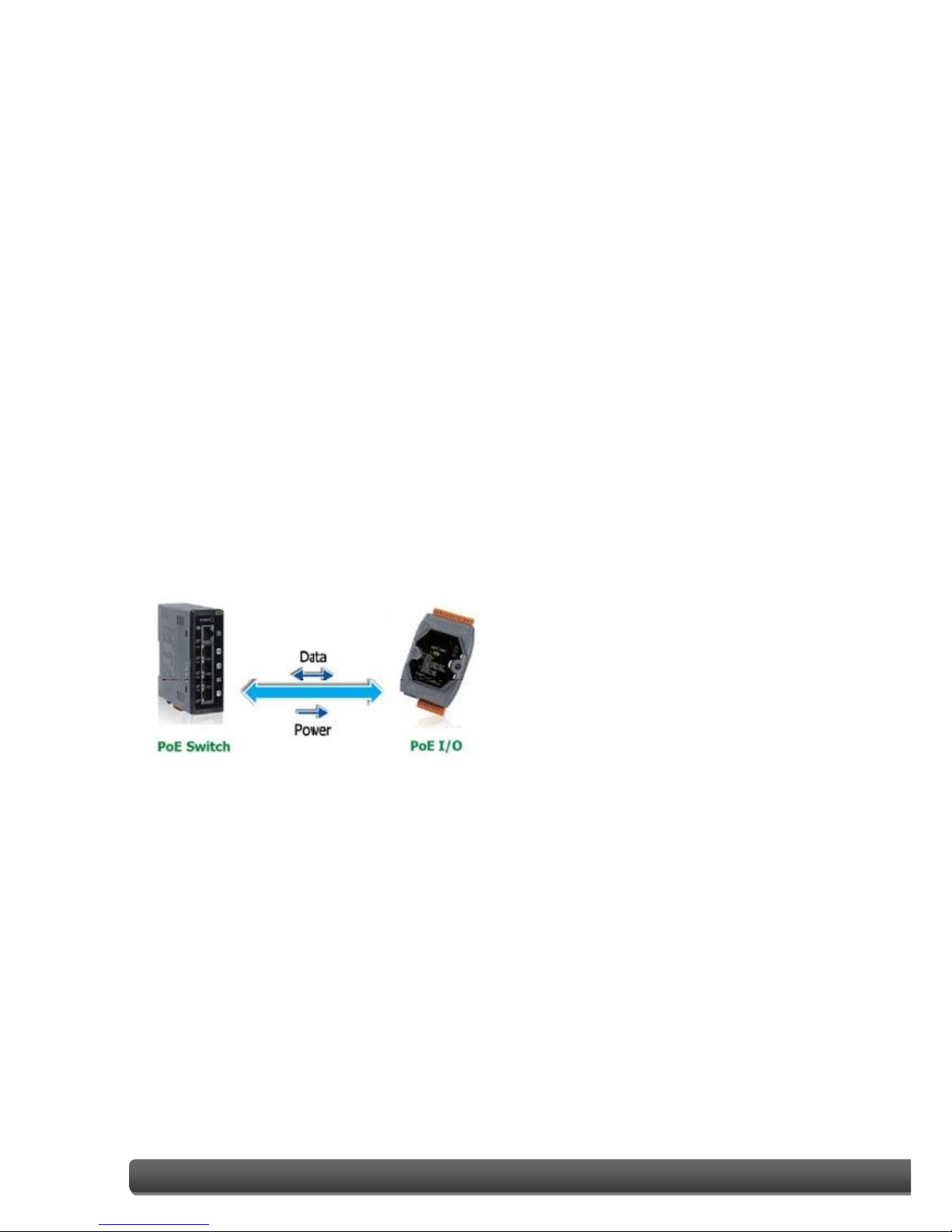
Furthermore, PET-7X00 features “PoE” that not only Ethernet but also power is carried
through an Ethernet cable. This feature makes installation of PET-7X00 a piece of cake.
Imagine that no more unnecessary wires, only an Ethernet cable takes care of everything in
the field.
ET-7X00/PET-7X00 User Manual, version 1.1.2 Page: 2
Copyright © 2013 ICP DAS CO., LTD. All Rights Reserved. E-mail: service@icpdas.com
Comparison between ET-7X00 and PET-7X00
The PET-7X00 has some unique features that different from the ET-7X00
PET-7X00 = Power over Ethernet + ET-7X00
The PET-7X00 includes integrated Power over Ethernet (PoE) technology that allows both
power and data to be carried over a single Ethernet cable, meaning that a device can
operate solely from the power it receives through the data cable. This innovation allows
greater flexibility in office design, higher efficiency in systems design, and faster
turnaround time in installation and implementation. The PET-7X00 features true IEEE
802.3af-compliant (classification, Class 1) PoE using both Ethernet pairs (Category 5
Ethernet cable). The PET-7X00 can also receive power from auxiliary power sources such as
DC adapters and external battery packs, in addition to the PoE-enabled network. This is a
desirable feature when the total system power requirements exceed the PoE's load
capacity. Furthermore, with the benefit of the auxiliary power option, the PET-7X00 can be
easily integrated into a standard Ethernet (non-PoE) system.
Industrial PoE Solution
The PoE switch is the ideal power source when using the PET-7X00 module. The PoE switch
automatically detects whether the connected devices are PoE-enabled or not, which
ensures that the PoE switch will function in conjunction with both PoE and non-PoE devices
simultaneously.
More information about the PET-7X00 series
There are two ways for PET-7X00 series devices to obtain power. The first is through the
Ethernet via a PoE switch; the second one is the usual method through wiring from an
external power source. External power source should range from +12 VDC to 48 VDC. The
reason that the second method has been retained is because it might still prove useful for
different applications in a variety of scenarios. The PET-7X00 is also equipped with an LED
to indicate whether or not the power is being supplied via a PoE Switch.
ET-7X00/PET-7X00 User Manual, version 1.1.2 Page: 3
Copyright © 2014 ICP DAS CO., LTD. All Rights Reserved. E-mail: service@icpdas.com
1.1. Features
The ET-7X00/PET-7X00 module offers the most comprehensive configuration focused on
meeting specific application requirements. The following details the features designed to
simplify installation, configuration and application.
Power over Ethernet (PoE)
The PET-7X00/PET-7X00 series module can be powered by an IEEE802.3af compliant
PoE switch. Both Ethernet and power can be carried by an Ethernet cable eliminating
the need for additional wiring and power supply.
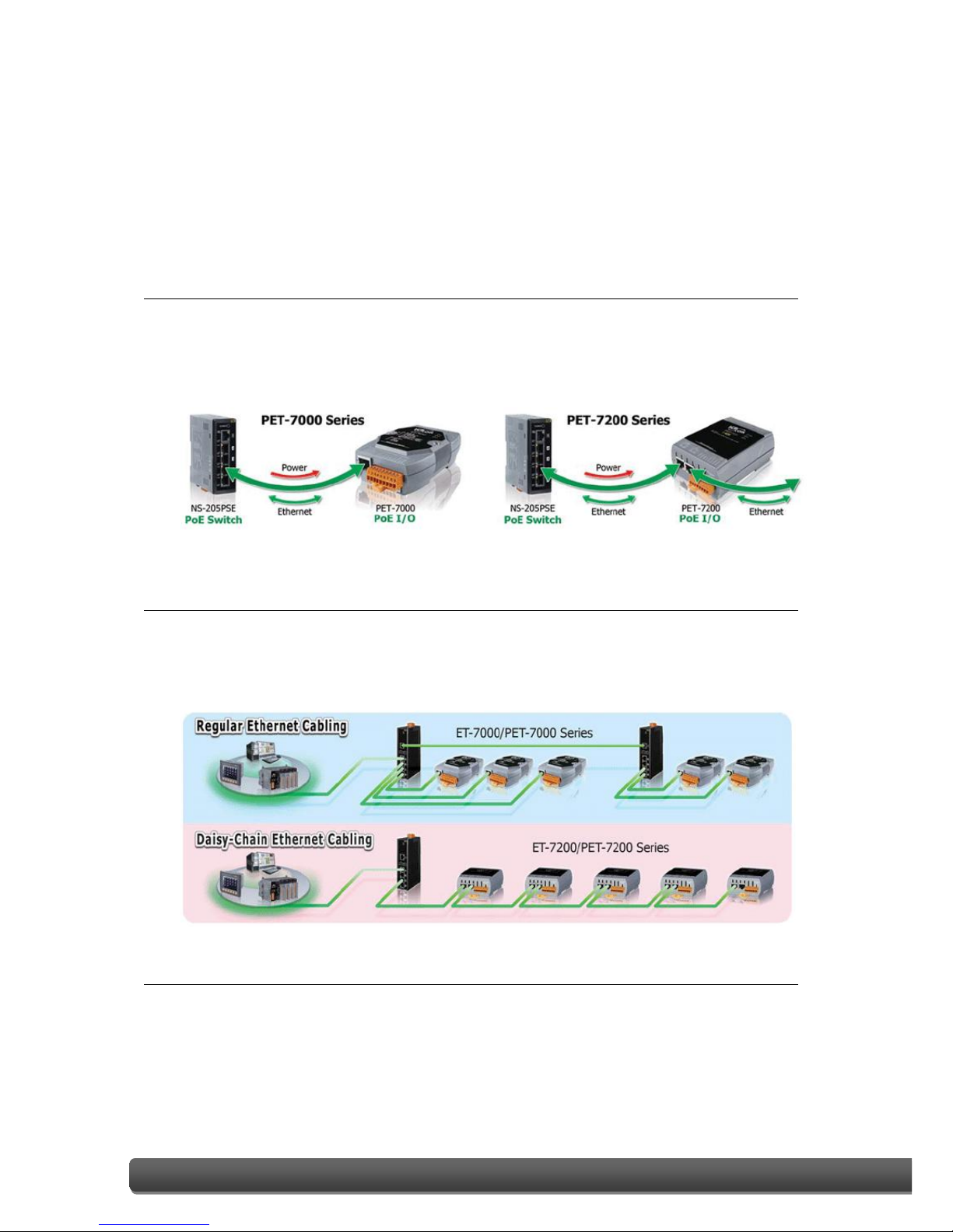
Daisy-Chain Ethernet Cabling
The ET-7200/PET-7200 Series has a built-in two-port Ethernet switch to implement
daisy-chain topology. The cabling is much easier and total costs of cable and switch
are significantly reduced.
LAN Bypass
LAN Bypass feature guarantees the Ethernet communication. It will automatically
active to continue the network traffic when the ET-7200/PET-7200 looses its power.

ET-7X00/PET-7X00 User Manual, version 1.1.2 Page: 4
Copyright © 2013 ICP DAS CO., LTD. All Rights Reserved. E-mail: service@icpdas.com
Communication Security
Account and password are needed when logging into the web server. An IP address
filter is also included, which can be used to allow or deny connections with specific IP
addresses.
Support for both Modbus TCP and Modbus UDP Protocols
The Modbus TCP, Modbus UDP slave function on the Ethernet port can be used to
provide data to remote SCADA software.
Built-in I/O
Various I/O components are mixed with multiple channels in a single I/O module,
which provides the most cost effective I/O usage and enhances performance of the
I/O operations.
Dual Watchdog
The Dual Watchdog is consists of a Module Watchdog and a Communication
Watchdog. The action of AO, DO are also associated to the Dual Watchdog.
Module Watchdog is a built-in hardware circuit to monitor the operation of the
module and will reset the CPU if a failure occurs in the hardware or the software.
Then the Power-on Value of AO, DO will be loaded.
Communication Watchdog is a software function to monitor the communication
between the host and the I/O module. The timeout of the communication Watchdog
is programmable, when the I/O doesn't receive commands from the host for a while,
the watchdog forces the AO, DO to pre-programmed Safe Value to prevent
unpredicatable damage of the connected devices.
Highly Reliable Under Harsh Environment
Wide Operating Temperature Range: -25 ~ +75°C
Storage Temperature: -30 ~ +80°C
Humidity 10 ~ 90% RH (Non-condensing)
ET-7X00/PET-7X00 User Manual, version 1.1.2 Page: 5
Copyright © 2013 ICP DAS CO., LTD. All Rights Reserved. E-mail: service@icpdas.com
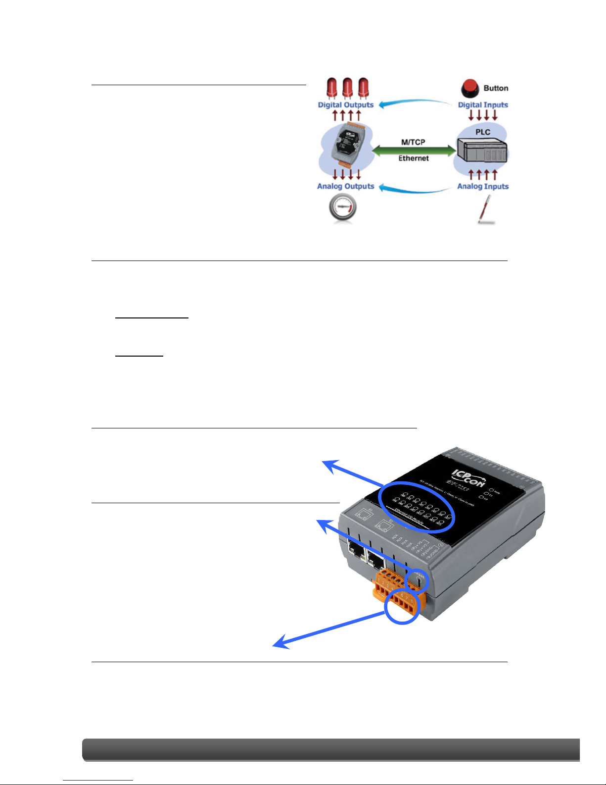
I/O Pair Connection
This function is used to create a AI/DI to
AO/DO pair through the Ethernet. Once
the configuration is completed, the I/O
module can poll the status of remote
AI/DI devices and then use the Modbus
TCP protocol to continuously write to a
local AO/DO channels in the background.
Power-on Value and Safe Value
Besides setting by the set AO, DO commands, the AO, DO can be set under two other
conditions.
Power-on Value: The Power-on Value is loaded into the AO, DO under 3 conditions:
Power-on, reset by Module Watchdog, reset by reset command.
Safe Value: When the Communication Watchdog is enabled and a Communication
Watchdog timeout occurs, the “safe value” is loaded into the AO, DO.
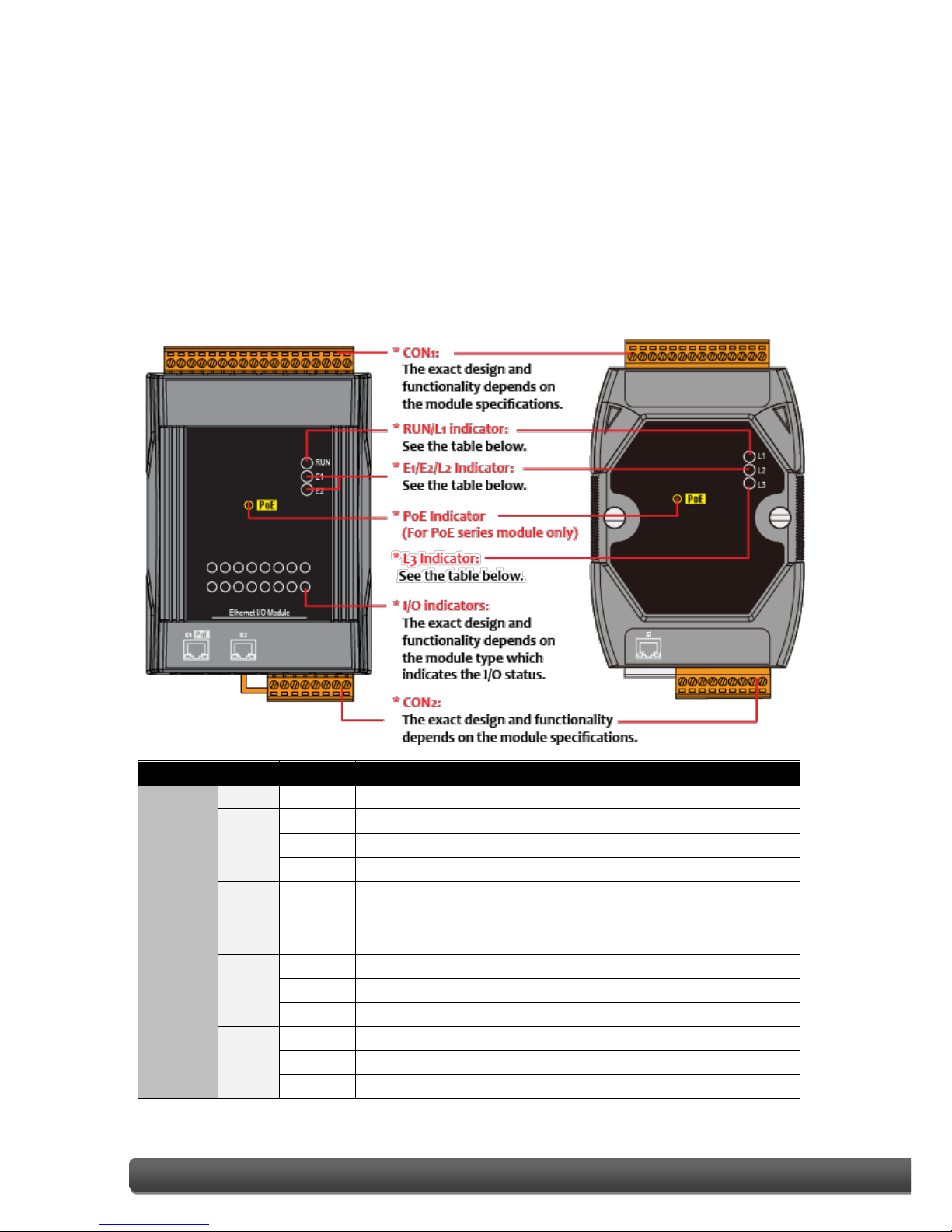
LED indicators for DIO status
The LED indicators for DIO status are for ET-7200/PET-7200 series.
Reset button
The reset button is for ET-7200/PET-7200
series. It is used to clears all data and
restore all settings to be factory default
values. It is very useful especially when you
forget the ID, password to log into the web server,
or IP address to access the Ethernet I/O module.
Two pair of power input pins
For ET-7000/PET-7000 series, there are only two pins for power input. To ease the
wiring, the pins are increased to four pins as two pairs for ET-7200/PET-7200 series.
ET-7X00/PET-7X00 User Manual, version 1.1.2 Page: 6
Copyright © 2014 ICP DAS CO., LTD. All Rights Reserved. E-mail: service@icpdas.com
1.2. Overview
The front panel of the ET-7X00/PET-7X00 module contains the Ethernet Port, connectors
and LEDs.
Please refer to the data sheets for specific ET-7X00/PET-7X00 models for details of pin
assignments, which can be found at:
http://ftp.icpdas.com/pub/cd/6000cd/napdos/et7000_et7200/document/data_sheet/
Model
Label
Status
Description
ET-7000/
PET-7000
L1
Flashing
The unit is turned on and is ready for use.
L2
On
A link has been established on the E1 port.
Off
No link is established on the E1 port.
Flashing
Data transmission or receiving activity is occurring on the E1 port.
L3
On
The E1 port is operating at 10 Mb/s.
Off
The E1 port is operating at 100 Mb/s.
ET-7200/
PET-7200
RUN
Flashing
The unit is turned on and is ready for use.
E1
On
A link has been established on the E1 port.
Off
No link is established on the E1 port.
Flashing
Data transmission or receiving activity is occurring on the E1 port.
E2
On
A link has been established on the E2 port.
Off
No link is established on the E2 port.
Flashing
Data transmission or receiving activity is occurring on the E2 port.

ET-7X00/PET-7X00 User Manual, version 1.1.2 Page: 7
Copyright © 2013 ICP DAS CO., LTD. All Rights Reserved. E-mail: service@icpdas.com
The bottom panel of the ET-7X00/PET-7X00 module contains the Ethernet port and the
reset button.
Reset button (for ET-7200/PET-7200 series modules only)
The reset button is used to restore the following settings to its factory defaults by
pressing and holding the reset button for 5 seconds.
▪ Network Settings
▪ Authentication
▪ Web HMI
▪ Pair Connection
For more information about these settings, please refer to section 3.2.2. (C) "Resetting
All Settings to Default”.
ET-7X00/PET-7X00 User Manual, version 1.1.2 Page: 8
Copyright © 2013 ICP DAS CO., LTD. All Rights Reserved. E-mail: service@icpdas.com
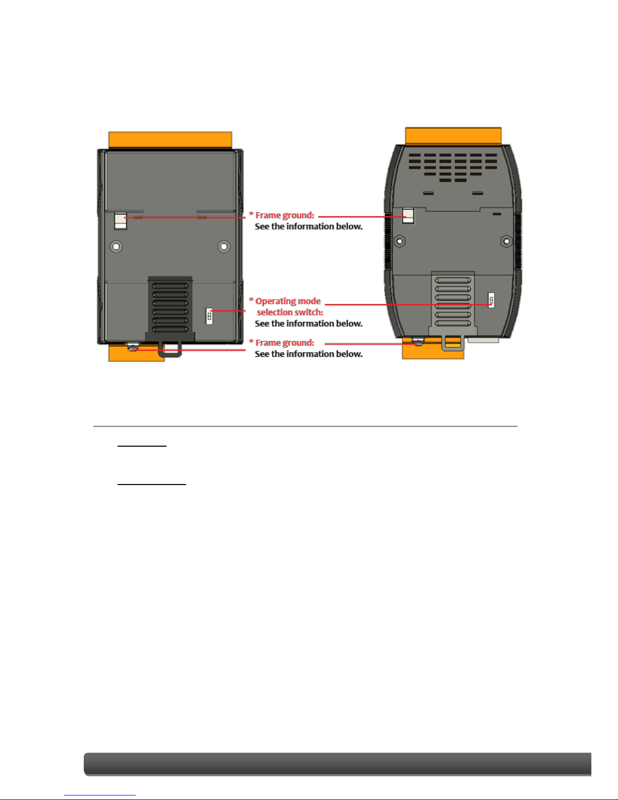
The back panel of the ET-7X00/PET-7X00 module contains the frame ground and the
operating mode selector switch.
Operating Mode Selector Switch
Init Mode:
This mode is used for MiniOS7 configuration.
Normal Mode:
This mode is used to execute and run firmware.
On the ET-7X00/PET-7X00 module, the operating mode selector switch should
usually be in the Normal position. The switch should only be moved from the Normal
position to the Init position when updating the ET-7X00/PET-7X00 firmware or the OS.
Once the update has been completed, ensure that the switch is returned to the
Normal position.
ET-7X00/PET-7X00 User Manual, version 1.1.2 Page: 9
Copyright © 2013 ICP DAS CO., LTD. All Rights Reserved. E-mail: service@icpdas.com
Frame Ground
Electronic circuits are constantly vulnerable to Electrostatic Discharge (ESD), which
becomes worse in a continental climate area. The ET-7X00/PET-7X00 series features a
new design for the frame ground that provides a path for bypassing ESD, allowing
enhanced static (ESD) protection capabilities and ensuring that the module is more
reliable.
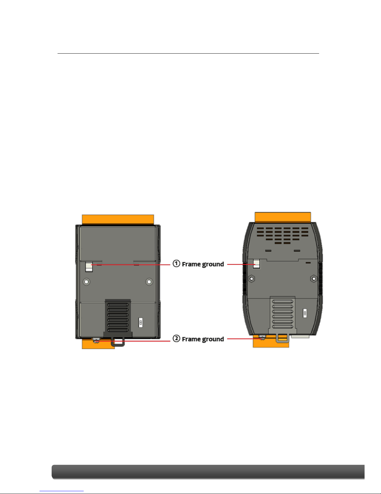
Choosing either of the following options will provide a better level of protection for
the module:
The ET-7X00/PET-7X00 has a metallic board attached to the back of the plastic case,
shown as “1” in the figure below.
When mounted to a DIN-Rail, connect the DIN-Rail to the earth ground because the
DIN-Rail is in contact with the upper frame ground, as shown as “2” in the figure
below.

ET-7X00/PET-7X00 User Manual, version 1.1.2 Page: 10
Copyright © 2014 ICP DAS CO., LTD. All Rights Reserved. E-mail: service@icpdas.com
1.3. Dimensions
The following diagrams provide the dimensions of the ET-7X00/PET-7X00 module and can
be used as a reference when defining the specifications for any custom enclosures. All
dimensions are in millimeters.
For the ET-7000, PET-7000: 72 x 123 x 35

ET-7X00/PET-7X00 User Manual, version 1.1.2 Page: 11
Copyright © 2013 ICP DAS CO., LTD. All Rights Reserved. E-mail: service@icpdas.com
For the ET-7200, PET-7200: 76 x 120 x 42

ET-7X00/PET-7X00 User Manual, version 1.1.2 Page: 12
Copyright © 2014 ICP DAS CO., LTD. All Rights Reserved. E-mail: service@icpdas.com
1.4. Companion CD
This package includes a companion CD that provides the drivers, a software utility, and all
of the required documentation, etc. An outline of the directory structure for the files
contained on the CD is shown below.
CD:\Napdos
ET7000_ET7200
Software
Demo
Document
Firmware
OS_image
ez_data_logger
minios7_utility
modbus_labview
modbus_master_tool
modbus_tcp_client
napopcsvr
PC_client
Modbus_TCP
Application
Data_sheet
ET7000
PET7000
ET7200_PET7200
ET7000_PET7000
ET7200_PET7200

ET-7X00/PET-7X00 User Manual, version 1.1.2 Page: 13
Copyright © 2013 ICP DAS CO., LTD. All Rights Reserved. E-mail: service@icpdas.com
2. Getting Started
If you are a new user, begin with this chapter as it includes a guided tour that provides a
basic overview of how to install, configure and use the ET-7X00/PET-7X00 module.
Before starting any task, please check the package contents. If any of the following items
are either missing or damaged, contact your dealer or distributor.
ET-7X00/PET-7X00 Software Utility CD Quick Start Guide
Before operating the ET-7X00/PET-7X00 module, a basic understanding of the hardware
specifications is required, such as the dimensions of the module, the usable input voltage
range of the power supply, and the type of communication interfaces.

ET-7X00/PET-7X00 User Manual, version 1.1.2 Page: 14
Copyright © 2014 ICP DAS CO., LTD. All Rights Reserved. E-mail: service@icpdas.com
2.1. Mounting the ET-7X00/PET-7X00
The ET-7X00/PET-7X00 module can be mounted by attaching the bottom of the chassis to a
DIN-Rail, to the wall, or by piggybacking it to another module.
DIN-Rail Mounting
The ET-7X00/PET-7X00 module
includes simple rail clips that
can be used to reliably mount it
on a standard 35 mm DIN-Rail.
Mounting the Chassis on a DIN-Rail
1. Hook the upper tab over the
upper flange of the DIN-Rail.
2. Tilt the module toward the DIN-Rail
until it snaps securely to rail.

ET-7X00/PET-7X00 User Manual, version 1.1.2 Page: 15
Copyright © 2013 ICP DAS CO., LTD. All Rights Reserved. E-mail: service@icpdas.com
Piggyback Mounting
The ET-7X00/PET-7X00 module has a
hole on either side of the casing that
can be used for piggyback mounting.

ET-7X00/PET-7X00 User Manual, version 1.1.2 Page: 16
Copyright © 2014 ICP DAS CO., LTD. All Rights Reserved. E-mail: service@icpdas.com
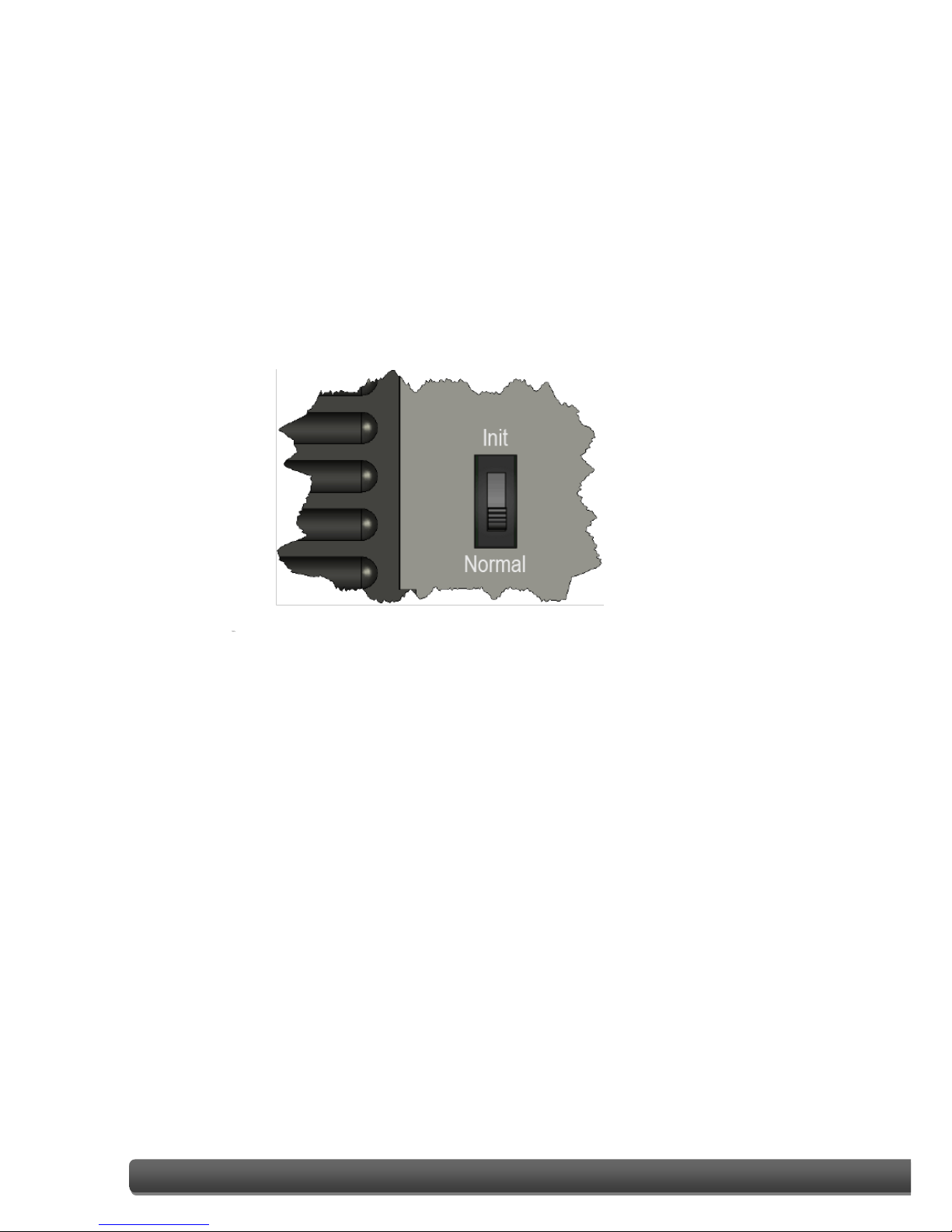
2.2. Configuring the Boot Mode
The ET-7X00/PET-7X00 module has two operating modes, which can be determined by the
switch mechanism on the chassis.
Init Mode
Init mode is a way to use MiniOS7
configuration mode.
Tips & Warnings
Init mode is a method to use MiniOS7 configuration mode and
update the software. After the update is completed, set the switch
to the Normal position.
Normal Mode
Normal mode is the default mode of
operation and the one you will use
most of the time. Use this mode for
more tasks and configurations.
Programs also are executed in this
mode.

ET-7X00/PET-7X00 User Manual, version 1.1.2 Page: 17
Copyright © 2013 ICP DAS CO., LTD. All Rights Reserved. E-mail: service@icpdas.com
2.3. ET-7X00/PET-7X00 Hardware Connections
ET-7X00/PET-7X00 series modules provide a variety of communication interfaces to suit a
range of applications. Below is a description of the configuration for simple applications
using the ET-7X00/PET-7X00 when implementing both PoE and Non-PoE solutions.
Non-PoE
i. Connect the PC to the Ethernet Port via the Hub or Switch.
ii. Connect the positive of the power supply to the terminal marked “(R)+Vs” on the
ET-7X00.
Connect the negative of the power supply to the terminal marked “(B)GND” on
the ET-7X00.

ET-7X00/PET-7X00 User Manual, version 1.1.2 Page: 18
Copyright © 2013 ICP DAS CO., LTD. All Rights Reserved. E-mail: service@icpdas.com
PoE
i. Connect the PC to the Ethernet Port via the PoE Switch.
ii. Connect the power supply to the PoE Switch, which in turn supplies power to the
PET-7X00.
Tips & Warnings
Only the E1 port of the PET-7X00 supports
the PoE feature.

ET-7X00/PET-7X00 User Manual, version 1.1.2 Page: 19
Copyright © 2014 ICP DAS CO., LTD. All Rights Reserved. E-mail: service@icpdas.com
2.4. Installing the MiniOS7 Utility
The MiniOS7 Utility is a useful tool that provides a quick and easy way to update the OS
image or the firmware, configure the Ethernet settings, and upload files to the
ET-7X00/PET-7X00 from a PC.
Step 1: Install the MiniOS7 Utility tool
The latest version of the MiniOS7 Utility can be obtained from the companion CD:
CD:\Napdos\Software\minios7_utility\
or from the ICP DAS FTP site at:
http://ftp.icpdas.com/pub/cd/6000cd/napdos/software/minios7_utility/
Step 2:Follow the instructions in the Setup Wizard to complete the installation
After the installation has been
completed, a new short cut for the
MiniOS7 Utility will be displayed on
your desktop.

ET-7X00/PET-7X00 User Manual, version 1.1.2 Page: 20
Copyright © 2013 ICP DAS CO., LTD. All Rights Reserved. E-mail: service@icpdas.com
2.5. Using the MiniOS7 Utility to Assign an IP Address
The ET-7X00/PET-7X00 is web-based device, and is configured using a default IP address,
meaning that you must first assign a new IP address to the ET-7X00/PET-7X00 before
operation.
The factory default IP settings are as follows:
Item
Default
IP Address
192.168.255.1
Subnet Mask
255.255.0.0
Gateway
192.168.0.1
Step 1:Run the MiniOS7 Utility
Double-click the “MiniOS7 Utility” shortcut on your desktop.
ET-7X00/PET-7X00 User Manual, version 1.1.2 Page: 21
Copyright © 2013 ICP DAS CO., LTD. All Rights Reserved. E-mail: service@icpdas.com
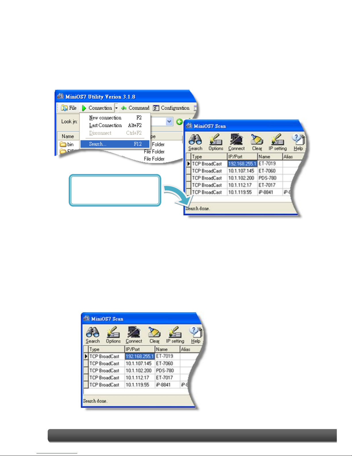
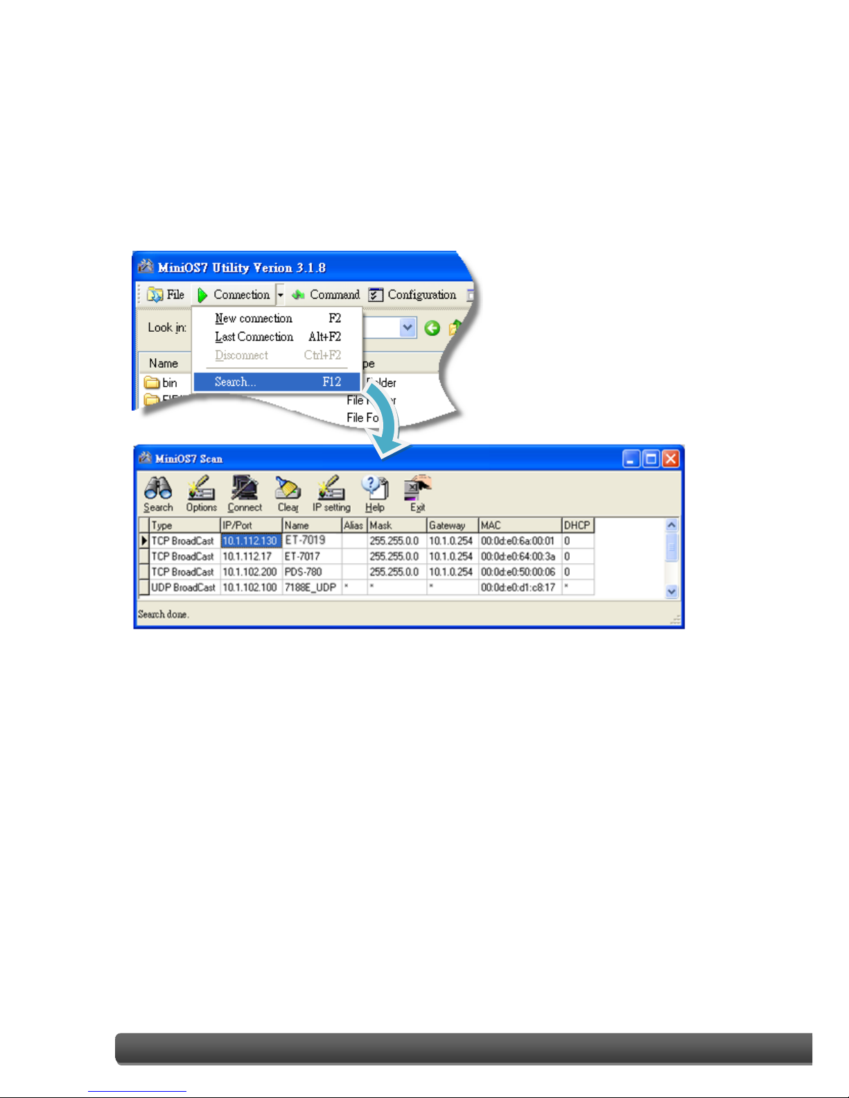
Step 2:Press the “F12” key or choose the “Search” option from the “Connection” menu
After pressing the “F12” key or choosing the “Search” option from
“Connection” menu, the utility will perform a search of all MiniOS7 modules
on your network.
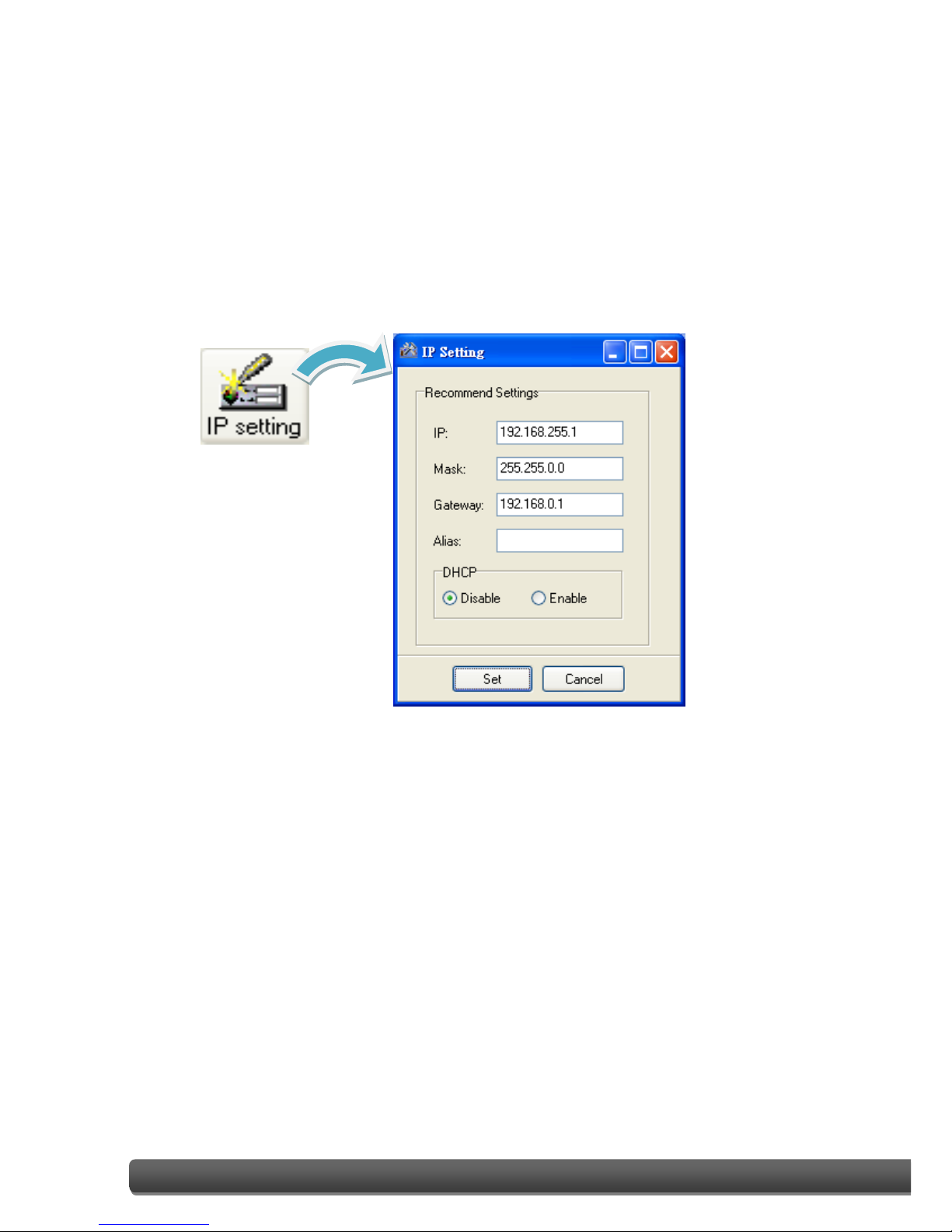
Step 3:Click the “192.168.255.1” item in the IP/Port field list and then click the “IP
Settings” icon in the toolbar
After the search has been completed, click the default value
“192.168.255.1” in the IP/Port field list, and then click the “IP Settings” icon
in the toolbar to display the IP Settings dialog box.
Check the status bar to monitor
for the progress of the search
ET-7X00/PET-7X00 User Manual, version 1.1.2 Page: 22
Copyright © 2013 ICP DAS CO., LTD. All Rights Reserved. E-mail: service@icpdas.com
Step 4:Assign a new IP address and then click the “Set” button
In the IP Settings dialog box, you can manually assign an IP Address, Mark
Address, Gateway and Alias, or you can use the DHCP function to
dynamically assign IP addresses.
Once the appropriate values have been entered, click the “Set” button to
save the settings.
ET-7X00/PET-7X00 User Manual, version 1.1.2 Page: 23
Copyright © 2013 ICP DAS CO., LTD. All Rights Reserved. E-mail: service@icpdas.com
Step 5:Reboot the module and then press the “F12” key or click the “Search” option
from the “Connection” menu to check the IP settings
After completing and saving the settings, you should reboot the module and
then use the MiniOS7 Utility to perform another search for the module to
make sure that the IP settings are correct. See Step 2 for details.
ET-7X00/PET-7X00 User Manual, version 1.1.2 Page: 24
Copyright © 2014 ICP DAS CO., LTD. All Rights Reserved. E-mail: service@icpdas.com
2.6. Enabling the Adobe Flash Player in Your Browser
The Web HMI page requires the Adobe Flash Player to be installed. The latest version of the
Adobe Flash Player can be downloaded by accessing the Adobe Systems Incorporated
website. The following instructions will help you to install the Adobe Flash Player in your
web browser.
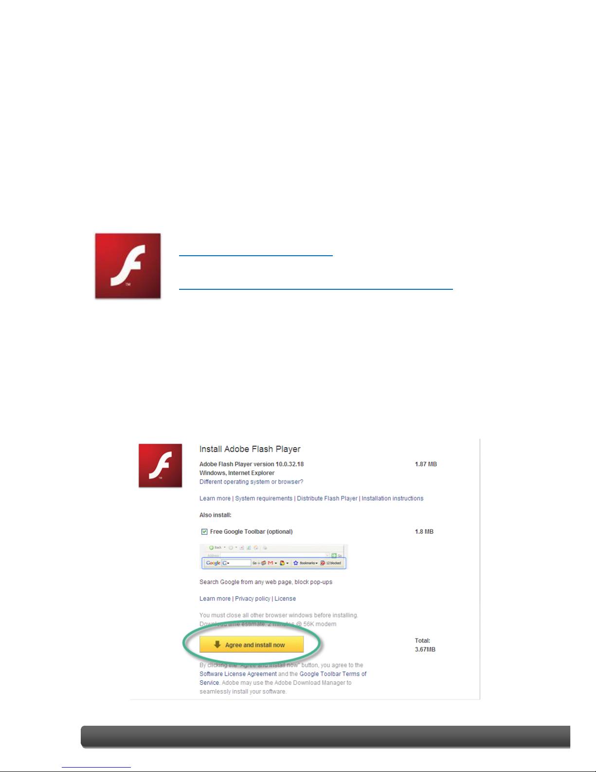
Step 1:Go to the Adobe Flash Player Download Center
The Adobe Flash Player Download Center:
http://get.adobe.com/flashplayer/
The Adobe Flash Player is subject to change without notice; refer to
http://www.adobe.com/support/flashplayer/downloads.html for the
latest version of this software.
Step 2:Follow the instructions to download the installation file
Click the “Agree and install now” button and follow the instructions to
download the installation file. Note that unless you uncheck the option, the
Google Toolbar will be included in the installation by default, so if you do
not require this feature, be sure to uncheck this option.
ET-7X00/PET-7X00 User Manual, version 1.1.2 Page: 25
Copyright © 2013 ICP DAS CO., LTD. All Rights Reserved. E-mail: service@icpdas.com
2.7. Configuring the I/O Functions
The ET-7X00/PET-7X00 series contains an advanced web configuration system that provides
users with access to ET-7X00/PET-7X00 series applications through a standard web browser.
Step 1:Be sure that the switch is set to the “Normal” position and then reboot the
module
Step 2:Open a browser
Use a standard internet browser to view the ET-7X00/PET-7X00 web pages,
such as Mozilla Firefox or Internet Explorer, etc.
Step 3:Enter the URL address for the ET-7X00/PET-7X00
If you haven’t changed the default IP address of the ET-7X00/PET-7X00
module, please refer to section 2.5. “Using the MiniOS7 Utility to Assign an
IP Address” to configure it.

ET-7X00/PET-7X00 User Manual, version 1.1.2 Page: 26
Copyright © 2013 ICP DAS CO., LTD. All Rights Reserved. E-mail: service@icpdas.com
Step 4:Enter your User name and Password
After entering the IP address, the login dialog box will appear, prompting you to
enter your user name and password.
The factory default user name and password are as follows:
Step 5:Welcome to the ET-7X00/PET-7X00 web interface
After logging into the ET-7X00/PET-7X00 web interface, the welcome page will be
displayed.
Item
Default
User name
Admin
Password
Admin

ET-7X00/PET-7X00 User Manual, version 1.1.2 Page: 27
Copyright © 2013 ICP DAS CO., LTD. All Rights Reserved. E-mail: service@icpdas.com
Step 6:Configure and browse the I/O functions
Click the “Web HMI” option in the “Web HMI”
section of the Main Menu for the
ET-7X00/PET-7X00, and then click the I/O function
tabs to configure and browse the I/O functions.
For more detailed information related to the I/O specification, pin assignment, and I/O
functions, etc. for each ET-7X00/PET-7X00, please refer to “ET7000_ET7200 Register Table”,
which can be obtained from:
CD:\NAPDOS\ET7000_ET7200\document\

ET-7X00/PET-7X00 User Manual, version 1.1.2 Page: 28
Copyright © 2013 ICP DAS CO., LTD. All Rights Reserved. E-mail: service@icpdas.com
3. Web Applications
The ET-7X00/PET-7X00 contains an advanced web configuration system that provides users
with access to ET-7X00/PET-7X00 applications through a standard web browser.
Logging into the ET-7X00/PET-7X00 web pages
You can log into the ET-7X00/PET-7X00 web pages from any computer that has Internet
access.
Step 1:Open a browser
Use a standard internet browser to view the ET-7X00/PET-7X00 web pages,
such as Mozilla Firefox or Internet Explorer, etc.
Step 2:Enter the URL address for the ET-7X00/PET-7X00
If you haven’t changed the default IP address of the ET-7X00/PET-7X00
module, please refer to section 2.5. “Using the MiniOS7 Utility to Assign an
IP Address” to configure it.

ET-7X00/PET-7X00 User Manual, version 1.1.2 Page: 29
Copyright © 2013 ICP DAS CO., LTD. All Rights Reserved. E-mail: service@icpdas.com
Step 3:Enter your User name and Password
After entering the IP address, the login dialog box will appear, prompting you to
enter your user name and password.
The factory default user name and password are as follows:
Item
Default
User name
Admin
Password
Admin

ET-7X00/PET-7X00 User Manual, version 1.1.2 Page: 30
Copyright © 2013 ICP DAS CO., LTD. All Rights Reserved. E-mail: service@icpdas.com
Step 4:Welcome to the ET-7X00/PET-7X00 web interface
After logging into the ET-7X00/PET-7X00 web interface, the welcome page will be
displayed.
This web interface provides a number of
functions, which can be easily accessed via the
menu on the left hand side of the page.

ET-7X00/PET-7X00 User Manual, version 1.1.2 Page: 31
Copyright © 2014 ICP DAS CO., LTD. All Rights Reserved. E-mail: service@icpdas.com
3.1. Overview
The “Overview” option in the Main menu provides
a brief introduction to and explanation of the web
interface.
The “Overview” option links to the welcome page
and contains two main parts.
The top section of the page provides some basic
information about both the ET-7X00/PET-7X00
hardware and software.

ET-7X00/PET-7X00 User Manual, version 1.1.2 Page: 32
Copyright © 2013 ICP DAS CO., LTD. All Rights Reserved. E-mail: service@icpdas.com
The lower section of the page provides a brief introduction to the web interface.

ET-7X00/PET-7X00 User Manual, version 1.1.2 Page: 33
Copyright © 2014 ICP DAS CO., LTD. All Rights Reserved. E-mail: service@icpdas.com
3.2. Configuration
The “Configuration” section of the Main menu contains the following options:
Network Settings:
Provides access to the Ethernet Settings page which
allows you to access the IP settings and check the
software version.
Basic Settings:
Provides access to the Basic Settings page which allows
you to configure the basic information for the web
interface.
Module I/O Settings:
Provides access to the Common Functions page which
allows you to configure the settings for the module I/O.

ET-7X00/PET-7X00 User Manual, version 1.1.2 Page: 34
Copyright © 2013 ICP DAS CO., LTD. All Rights Reserved. E-mail: service@icpdas.com
3.2.1. Network Settings
The Network Settings page allows you to perform the following functions:
(A) Configure the network settings
(B) Check the software information
(A) Configuring the Network Settings
In general, network settings include the following parameters:
● An IP address: Each ET-7X00/PET-7X00 on the network must have a unique IP address.
● A default gateway: A gateway (or router) is a system that is used to connect a network
with one or more other networks.
● A subnet mask: The subnet mask indicates which portion of the IP address that is used to
identify the local network or subnet.
There are two methods of configuring the network settings:
● Dynamic configuration: The Dynamic Host Configuration Protocol (DHCP) is a network
application protocol that automatically assigns an IP address to a device.
● Manual configuration: In the absence of DHCP, ET-7X00/PET-7X00 modules can be
manually configured with an IP address, mask, and a gateway.
A
B

ET-7X00/PET-7X00 User Manual, version 1.1.2 Page: 35
Copyright © 2013 ICP DAS CO., LTD. All Rights Reserved. E-mail: service@icpdas.com
Dynamic Configuration
If a DHCP server is present on the network, the ET-7X00/PET-7X00 will automatically obtain
the network settings from the DHCP server when the DHCP function is enabled.
Step 1:Enable the DHCP by checking the “Enabled” radio button.
Step 2:Click the “Modify Settings” button to finish configuring the network settings.
Manual Configuration
When using manual configuration, all network settings need to be assigned manually. Each
ET-7X00/PET-7X00 module should have a unique IP address assigned to the interface in
order to identify itself on the network.
Step 1:Disable the DHCP by checking the “Disabled” radio button.
Step 2:Enter the relevant network settings information into the respective fields .
Step 3:Click the “Modify Settings” button to finish configuring the network settings.
1
2
1
3
2

ET-7X00/PET-7X00 User Manual, version 1.1.2 Page: 36
Copyright © 2014 ICP DAS CO., LTD. All Rights Reserved. E-mail: service@icpdas.com
(B) Checking the Software Information
The software information section includes the following items:
● Web Server Lib. Version: This item provides details of the version number for the web
server library, which is a collection of web development solutions that are providing by
ICPDAS for use with custom applications.
● MiniOS7 Version: This item provides defaults of the version number for the MiniOS7 OS
image, which is an embedded operating system specifically designed for use with ICP
DAS controllers.
This page can be used to check the version information for the ET-7X00/PET-7X00
software after updating the ET-7X00/PET-7X00 firmware (see section 6.4 . “Uploading the
ET-7X00/PET-7X00 firmware” for more details).

ET-7X00/PET-7X00 User Manual, version 1.1.2 Page: 37
Copyright © 2014 ICP DAS CO., LTD. All Rights Reserved. E-mail: service@icpdas.com
3.2.2. Basic Settings
The “Basic Settings” page allows you to perform the following functions:
(A) Configure the module information
(B) Configure the web interface information
(C) Reset all parameters to the default settings
C A B

ET-7X00/PET-7X00 User Manual, version 1.1.2 Page: 38
Copyright © 2014 ICP DAS CO., LTD. All Rights Reserved. E-mail: service@icpdas.com
(A) Configuring the Module Information
The “Module Information” section includes the following items:
● Module Name: The initial value for this field will depend on the model of the module
and can not be modified.
● Module Information: The module information field indicates the name of the alias that
is used to identify the module.
To configure the module information, follow the procedure below:
Step 1:Enter the Module information in the relevant field.
Step 2:Click the “Submit” button to finish configuring the module information.
1
2

ET-7X00/PET-7X00 User Manual, version 1.1.2 Page: 39
Copyright © 2014 ICP DAS CO., LTD. All Rights Reserved. E-mail: service@icpdas.com
(B) Configuring the Web Interface Information
The module information section includes the following items:
● Page Header Information (First line) and Page Header Information (Second line):
The title of the website that is displayed the top left-hand corner of the interface, for
example the company name and web address as per the example below.
● More Information URL:
This item allows you to specify the URL that will be displayed when the “More
information” option in the Main Menu is clicked in order to provide additional support
for the ET-7X00/PET-7X00. After completing the settings, click the “More Information”
option to check that the link to the web site is correct (As per the figure below).

ET-7X00/PET-7X00 User Manual, version 1.1.2 Page: 40
Copyright © 2014 ICP DAS CO., LTD. All Rights Reserved. E-mail: service@icpdas.com
● Web Server Port: This option specifies which port is to be used for the web server. By
default, the HTTP port is 80.
● Modbus TCP Port: This option specifies which port is to be used for communication on
the Modbus TCP. By default, the Modbus protocol uses port 502.
● Modbus TCP Port (WAN): This option specifies which port is to be used for Modbus
communication between the remote host and local EX-7X00/PET-7X00. This settings can
be ignored if ET-7X00/PET-7X00 is not located behind a router.
To configure the web interface information, follow procedure below:
Step 1:Enter the desired information into the respective fields.
Step 2:Click the “Submit” button to finish configuring the module information.
1
2

ET-7X00/PET-7X00 User Manual, version 1.1.2 Page: 41
Copyright © 2013 ICP DAS CO., LTD. All Rights Reserved. E-mail: service@icpdas.com
(C) Resetting All Settings to Default
The reset function is divided into categories based on the menu options for the web
interface, and can be used to restore the individual settings to their factory default state.
Tips & Warnings
For ET-7200/PET-7200 modules,
in addition to using the reset
function in the web-based Basic
Settings page, you can also use
the reset button to restore the ET-7200/PET-7200 to
factory defaults. For more information about the reset
button, please refer to section 1.2. “Overview”.
To reset the settings to their factory default, follow the procedure below:
Step 1:Check the relevant check boxes for the items you wish to reset.
Step 2:Click the “Submit” button to reset the settings to their factory default state.
1
2

ET-7X00/PET-7X00 User Manual, version 1.1.2 Page: 42
Copyright © 2013 ICP DAS CO., LTD. All Rights Reserved. E-mail: service@icpdas.com
(a) Factory Default Settings for the “Configuration” Menu Options
The tables below outline the factory default settings for the items listed in the
“Configuration” menu.
Network Settings
Ethernet Settings
Item
Factory Default Settings
IP Address
192.168.255.1
Gateway
192.168.0.1
Subnet Mask
255.255.0.0
DHCP
Disabled
Basic Settings
Basic Settings
Item
Factory Default Settings
Module Name
Depends on the name of the module
Module Information
Empty
Page Header Information (First line)
ICP DAS
Page Header Information (Second line)
http://www.icpdas.com
More Information URL
http://www.icpdas.com/root/product/soluti
ons/remote_io/ethernet_io/et-7000_introdu
ction.html
Web Server Port
80
Modbus TCP Port
502
Modbus TCP Port (WAN)
502

ET-7X00/PET-7X00 User Manual, version 1.1.2 Page: 43
Copyright © 2013 ICP DAS CO., LTD. All Rights Reserved. E-mail: service@icpdas.com
Module I/O Settings
The information displayed on the settings page varies depending on the model number.
Common Functions
Item
Factory Default Settings
Host WDT Timeout
0 (Disabled)
WDT Event Counter
0
Modbus NetID
1
Digital Output
Item
Factory Default Settings
Power-on Value
OFF
Safe Value
OFF
Digital Input
Item
Factory Default Settings
DI Latch Status
Disabled
DI Counter
Disabled
Analog Output
Item
Factory Default Settings
Output Range
This value varies depending on the
model of the module
Output Slew Rate
0 (Immediate)
Power-on Value
0
Safe Value
0
Data Format
2’s Comp
Hexadecimal
2’s Comp Hexadecimal
Engineering Unit

ET-7X00/PET-7X00 User Manual, version 1.1.2 Page: 44
Copyright © 2013 ICP DAS CO., LTD. All Rights Reserved. E-mail: service@icpdas.com
Analog Input
Item
Factory Default Setting
Input Range
This value varies depending on the model
of the module
Enable
ON
High Alarm
Alarm Limit Value
This value varies depending on the model
of the module
Enable
OFF
Alarm Mode
Momentary
Low Alarm
Alarm Limit Value
This value varies depending on the model
of the module
Enable
OFF
Alarm Mode
Momentary
Sampling Rate
Normal mode
(10 Hz)
Normal mode
Fast mode
(50 Hz)
Filter Setting
60 Hz Rejection
60 Hz Rejection
50 Hz Rejection
Data Format
2’s Comp
Hexadecimal
2’s Comp Hexadecimal
Engineering Unit
Note: The analog input and the analog output share the same data format settings.

ET-7X00/PET-7X00 User Manual, version 1.1.2 Page: 45
Copyright © 2013 ICP DAS CO., LTD. All Rights Reserved. E-mail: service@icpdas.com
(b) Factory Default Settings for the “Authentication” Menu Options
The tables below outline the factory default settings for the items listed in the
“Authentication” menu.
Account Management
Factory Default Settings
A default user account consists of an account name, “Admin”, and a password, “Admin”.
Accessible IP Settings
Factory Default Settings
Empty, there is no limit allowing any outgoing access.

ET-7X00/PET-7X00 User Manual, version 1.1.2 Page: 46
Copyright © 2013 ICP DAS CO., LTD. All Rights Reserved. E-mail: service@icpdas.com
(c) Factory Default Settings for “Web HMI” Menu Option
The tables below outline the factory default settings for the items listed in the “Web HMI”
menu.
Web HMI
Factory Default Settings
Depends on the Modbus setting function of the ET-7X00/PET-7X00.
Web Edit
Factory Default Settings
0 Pages

ET-7X00/PET-7X00 User Manual, version 1.1.2 Page: 47
Copyright © 2013 ICP DAS CO., LTD. All Rights Reserved. E-mail: service@icpdas.com
(d) Factory Default Settings for the “I/O Pair Connection” Menu Option
The table below outlines the factory default settings for the “Pair Connection” option.
Pair Connection
Factory Default Settings
Empty

ET-7X00/PET-7X00 User Manual, version 1.1.2 Page: 48
Copyright © 2014 ICP DAS CO., LTD. All Rights Reserved. E-mail: service@icpdas.com
3.2.3. Module I/O Settings
After completing the general configuration of the ET-7X00/PET-7X00 module described in
the previous section, the settings for the input and output channels need to be configured,
such as the channel range and the alarm, etc.
Tips & Warnings
The contents displayed on this page will be depending on the Modbus
functions applicable to the specific the ET-7X00/PET-7X00 module. Please
refer to the user manual for each module for details of how to configure the
relevant I/O settings.
In this example, the ET-7026/PET-7026 will be used in order to explain the I/O settings. (The
ET-7026/PET-7026 is a multi-function module that has 6 AI channels, 2 AO channels, 2 DI
channels and 2 DO channels.)

ET-7X00/PET-7X00 User Manual, version 1.1.2 Page: 49
Copyright © 2014 ICP DAS CO., LTD. All Rights Reserved. E-mail: service@icpdas.com
(A) Common Functions
The Common Functions area provides options that allow the settings for the Modbus
functions to be configured.

ET-7X00/PET-7X00 User Manual, version 1.1.2 Page: 50
Copyright © 2014 ICP DAS CO., LTD. All Rights Reserved. E-mail: service@icpdas.com
(B) Digital Output Settings
The Digital Output settings area provides details of the configuration settings for all digital
output channels.
Power-on Value: This section is used to set the power-on value for a specific digital
output channel. The digital output channel will then generate the start-up value
output.
Safe Value: When communication between the Host PC and the ET-7X00/PET-7X00
module interrupted is broken, the digital output channels can generate a predefined
safe value. This function can be enabled by configuring the Host WDT Timeout setting.
For a more detailed description of these Modbus functions, please refer to: “Appendix C.
Modbus Application Notes”.

ET-7X00/PET-7X00 User Manual, version 1.1.2 Page: 51
Copyright © 2014 ICP DAS CO., LTD. All Rights Reserved. E-mail: service@icpdas.com
(C) Digital Input Settings
All digital input channels in ET-7X00/PET-7X00 modules can be used as 32-bit counters and
each counter consists of two address values, the Low word and the High word. Specific
individual DI channels can be counters via the Digital Input settings web page.
DI Latched: When DI Latch function is enabled, once the digital input channel detects
any change in input status, the input status will be latched and will remain in this
condition the latch is manually.
DI Counter: When Counter mode is selected, one counter will record the number of
pulses from the digital signal for the selected channel, and will then record the count
value in the register.
Preset Value: This option allows the default values for the counters to be set.

ET-7X00/PET-7X00 User Manual, version 1.1.2 Page: 52
Copyright © 2014 ICP DAS CO., LTD. All Rights Reserved. E-mail: service@icpdas.com
(D) Analog Output Settings
The Analog Output settings area contains two parts, the Basic Settings section and the
Power-on/Safe Values section, which will be described in detail below.
Tips & Warnings
Before selecting the output range for each analog output channel, make
sure that the jumpers are set properly.
For more detailed technical specifications related to the jumper settings for
each ET-7X00/PET-7X00 module, please refer to “ET7000_ET7200 Register
Table”, which can be obtained from:
CD:\NAPDOS\ET7000_ET7200\document\

ET-7X00/PET-7X00 User Manual, version 1.1.2 Page: 53
Copyright © 2013 ICP DAS CO., LTD. All Rights Reserved. E-mail: service@icpdas.com
Range: In a manner, a different range can be set for each individual analog output
channel. Select the required voltage/current range from the respective drop-down
menus. For more detailed technical specifications related to the output range for each
analog output channel, please refer to: "Appendix E. Analog Output Type and Data
Format Table".
Slew Rate: This is the programmable output slew rate for the analog output channels,
i.e., the rate of change in the analog output voltage/current as it changes from one
output voltage/current to another. Select the most appropriate value from the
respective drop-down menus.
Power-on Value: A power-on value can be set for a specific analog output channel, and
the analog output channel will then generate the start-up value output.
Safe Value: When communication between the Host PC and the ET-7X00/PET-7X00
module is interrupted, the analog output channels can generate a predefined safe
value. This function can be enabled or disabled by configuring the Host WDT Timeout
setting.
For a more detailed description of these Modbus functions, please refer to: “Appendix C.
Modbus Application Notes”.

ET-7X00/PET-7X00 User Manual, version 1.1.2 Page: 54
Copyright © 2013 ICP DAS CO., LTD. All Rights Reserved. E-mail: service@icpdas.com
(E) Analog Input Settings
Analog Input Settings area contains two parts, the Basic Settings section and the Alarm
Settings section, which will be described in detail below.
Tips & Warnings
Before selecting the input range for each analog input channel, make sure
that the jumpers are set properly.
For more detailed technical specifications related to the jumper settings for
each ET-7X00/PET-7X00 module, please refer to “ET7000_ET7200 Register
Table”, which can be obtained from:
CD:\NAPDOS\ET7000_ET7200\document\

ET-7X00/PET-7X00 User Manual, version 1.1.2 Page: 55
Copyright © 2013 ICP DAS CO., LTD. All Rights Reserved. E-mail: service@icpdas.com
Range: ET-7X00/PET-7X00 modules provide a programmable input voltage/current
range on all analog inputs channels, where a different range can be set for each
individual analog input channel. Select the required voltage/current from the
respective drop-down menus. For more detailed technical specifications related to the
input range for each analog input channel, please refer to: “Appendix D. Analog Input
Type and Data Format Table”.
Enable: This section allows each analog input channel to be switched ON or OFF.
Normal/Fast Mode: ET-7X00/PET-7X00 modules support sample rates in either
“Normal” or “Fast” mode. Fast mode uses 60 Hz with a 12-bit resolution, while Normal
mode uses 10 Hz with a 16-bit resolution.
50/60Hz Rejection for AI: In order to remove the noise from the power supply,
ET-7X00/PET-7X00 analog input modules feature two built-in rejection filters, that
operate at different frequencies, 50 or 60 Hz, that are designed to remove noise
generated by different power supplies.
AI Data Format: ET-7X00/PET-7X00 modules allow data to be displayed in either
hexadecimal or engineering unit format. For more detailed technical specifications
related to the data format for each analog input channel, please refer to: “Appendix D.
Analog Input Type and Data Format Table”.

ET-7X00/PET-7X00 User Manual, version 1.1.2 Page: 56
Copyright © 2014 ICP DAS CO., LTD. All Rights Reserved. E-mail: service@icpdas.com
(F) Analog Input Alarm Settings
The ET-7X00/PET-7X00 modules feature a built-in alarm function. The alarm includes two
parts, the high alarm and the low alarm and each need to be configured for a specific
channel.
Value: You can define both the high alarm value and the low alarm value using the
Alarm Value text box. When the analog input value is higher than the high alarm value,
or lower than the low alarm value, an alarm occurs. The alarm status will then be
activated and switched to on.
Enable: Each analog input alarm can be switched to on or off by clicking the
appropriate radio button.
Mode: The ET-7X00/PET-7X00 allows the alarm to be selected as either Momentary or
Latch mode, which can be set using the Mode combo box for both the low alarm and
the high alarm.
Latch Mode: Once an alarm occurs, the alarm status will be activated and set to the
logic high level. This value will remain until the alarm is cleared manually.
Momentary Mode: In this mode, the alarm status will dynamically change depending
on whether or not an alarm has occurred. If an alarm occurs, the alarm status will be
set to on. If the alarm is deactivated, the alarm status will be set to off.

ET-7X00/PET-7X00 User Manual, version 1.1.2 Page: 57
Copyright © 2014 ICP DAS CO., LTD. All Rights Reserved. E-mail: service@icpdas.com
3.3. Authentication
The “Authentication” section of the Main Menu contains the following options:
Account Management:
Provides access to the privilege management page,
which allows you to manage user accounts and their
associated privileges.
Accessible IP Settings:
Provides access to the IP Filter Settings page, which
allows you to control access to the web site.

ET-7X00/PET-7X00 User Manual, version 1.1.2 Page: 58
Copyright © 2013 ICP DAS CO., LTD. All Rights Reserved. E-mail: service@icpdas.com
3.3.1. Account Management
The Account Management page provides functions that allow the following tasks to be
performed:
(A) Configuration of user accounts
(B) Restoration of the factory default user account

ET-7X00/PET-7X00 User Manual, version 1.1.2 Page: 59
Copyright © 2013 ICP DAS CO., LTD. All Rights Reserved. E-mail: service@icpdas.com
(A) Configuring the User Accounts
The ET-7X00/PET-7X00 interface supports a maximum of five user accounts, including:
● A Built-in Administrator Account
The built-in Administrator account is basically a setup and disaster recovery account
that can be deleted. You can, however, change the password for the administrator
account.
● Four User-defined Accounts
Each user account consists of an account name, a password and an authority level.
The authority level includes the following roles, which determine the type of
operations the user is allowed to perform.
Admin: This level enables access to all ET-7X00/PET-7X00 web site features,
functions, and commands.
User: This level enables limited access to the ET-7X00/PET-7X00 web site features,
functions, and commands. In general, operators at this level cannot change
configuration settings.
Once a user account has been created, it can be either enabled or disabled.
To add a new user account, perform the followings:
Step 1:Enter the user account information into the relevant text fields, and then select
the “Enable” checkbox.
Step 2:Click the “Submit” button to complete the user account configuration and save
the details.
1
2

ET-7X00/PET-7X00 User Manual, version 1.1.2 Page: 60
Copyright © 2013 ICP DAS CO., LTD. All Rights Reserved. E-mail: service@icpdas.com
(B) Restoring the Factory Default User Accounts
The ET-7X00/PET-7X00 has a built-in administrator account named Admin that is created by
default. The default account cannot be deleted.
To restore the factory default user accounts, perform the followings:
Step 1:Select the “Load Setup Default” checkbox.
Step 2:Click the “Submit” button to restore the factory default user accounts.
1
2

ET-7X00/PET-7X00 User Manual, version 1.1.2 Page: 61
Copyright © 2013 ICP DAS CO., LTD. All Rights Reserved. E-mail: service@icpdas.com
3.3.2. Accessible IP Settings
The IP Filter Settings page provides functions that allow the following tasks to be
performed:
● Configuration of the connection filtering

ET-7X00/PET-7X00 User Manual, version 1.1.2 Page: 62
Copyright © 2013 ICP DAS CO., LTD. All Rights Reserved. E-mail: service@icpdas.com
(A) Configuring IP Filter
The ET-7X00/PET-7X00 includes an IP filter that enables you to restrict or grant user access
based on a custom IP filter list that you create.
The filter can be enabled by selecting the “Enable the IP filter table” checkbox. After this
option is selected, only requests from the IP addresses included in the list will be allowed
access to the module.
Tips & Warnings
By default, there is no restriction on outgoing access.
Each filter list entry can be either activated or deactivated by selecting the respective
“Activate the Rule” checkbox.

ET-7X00/PET-7X00 User Manual, version 1.1.2 Page: 63
Copyright © 2013 ICP DAS CO., LTD. All Rights Reserved. E-mail: service@icpdas.com
(B) Configuring the IP Filters
Two methods are provided for configuring the IP filter, allowing filtering for either
individual IP addresses, or across a range (group) of IP addresses.
Method 1: Allow access from a single IP address
Step 1:Select the “Enable the IP filter table” checkbox.
Step 2:Enter the same IP address in both the “From (IP Address)” and the “To (IP
Address)” text boxes. (The IP address may be the address of the PC currently
being used or others)
Step 3:Select the “Activate the Rule” checkbox.
Step 4:Click the “Submit” button to complete the configuration of the IP filter list and
save the settings.
4
1 2 3

ET-7X00/PET-7X00 User Manual, version 1.1.2 Page: 64
Copyright © 2013 ICP DAS CO., LTD. All Rights Reserved. E-mail: service@icpdas.com
Method 2: Allow access from a group of IP addresses
Step 1:Select the “Enable the IP filter table” checkbox
Step 2:Enter the first IP address in the range in the “From (IP Address)” and enter the
final IP address in the range in the “To (IP Address)” text boxes.
Step 3:Select the “Activate the Rule” checkbox.
Step 4:Click the “Submit” button to complete the configuration of the IP filter list and
save the settings.
4
1 2 3

ET-7X00/PET-7X00 User Manual, version 1.1.2 Page: 65
Copyright © 2014 ICP DAS CO., LTD. All Rights Reserved. E-mail: service@icpdas.com
3.4. Web HMI
The “Web HMI” section of the Main Menu contains the following options:
Web HMI:
Provides access to the I/O monitor page, which allows
you to remotely monitor and control the I/O status of
the ET-7X00/PET-7X00 module.
Web Edit:
Provides access to the Web interface Configuration
page, which allows you to create dynamic web HMI
pages.

ET-7X00/PET-7X00 User Manual, version 1.1.2 Page: 66
Copyright © 2014 ICP DAS CO., LTD. All Rights Reserved. E-mail: service@icpdas.com
3.4.1. Web HMI
The ET-7X00/PET-7X00 module features a Web HMI web interface that can be used to
display real-time I/O data values and alarms via the LAN or the Internet. Real-time I/O
data values and alarms can be monitored at either the local or remote site using any web
browser. Then, the Web HMI is completed immediately without requiring any
programming skills.

ET-7X00/PET-7X00 User Manual, version 1.1.2 Page: 67
Copyright © 2013 ICP DAS CO., LTD. All Rights Reserved. E-mail: service@icpdas.com
3.4.2. Web Edit
The ET-7X00/PET-7X00 module provides functions that enable users to create customized
web pages. Users can upload specific I/O layout diagrams in either bmp, jpg, or gif format
and can define a description for each I/O point. No HTML or Java skills are required in order
to create the web pages.

ET-7X00/PET-7X00 User Manual, version 1.1.2 Page: 68
Copyright © 2013 ICP DAS CO., LTD. All Rights Reserved. E-mail: service@icpdas.com
By default, no pages are listed on the initial “Web Page Configuration” page.
The ET-7X00/PET-7X00 Web Edit function allows the creation of up to 10 user-defined web
pages.
A maximum of 10 pages can be created

ET-7X00/PET-7X00 User Manual, version 1.1.2 Page: 69
Copyright © 2013 ICP DAS CO., LTD. All Rights Reserved. E-mail: service@icpdas.com
Below is an example of how to create a customized web page.
Example
Objective:
Create a Web page to monitor the I/O status of a conveyor system, as shown below. The
I/O system contains a sensor that is used to detect the products, and a switch that is used
to turn the conveyor motor on and off.
Step 1:Add a New Page
Click the “Add a new Page” button to begin creating a new page.

ET-7X00/PET-7X00 User Manual, version 1.1.2 Page: 70
Copyright © 2013 ICP DAS CO., LTD. All Rights Reserved. E-mail: service@icpdas.com
Step 2:Upload an Image
Click the “Browse…” button to select an image, and then click the “Upload”
button to upload the image to the ET-7X00/PET-7X00 module, as shown in
the figure below.
Tips & Warnings
The image can be in either .jpg, .gif, or .bmp format with a maximum file
size of 64 kb. The recommended resolution for the image to be displayed on
the editing Web page is 340 * 250 pixels.
After the upload is completed, the image information will be displayed and the image will
be added to the “Image” dropdown list box, as shown below.
2. Click the “Upload” button to upload the image
1. Click the “Browse…” button to select an image
Image information
File name added to the
Image dropdown list box

ET-7X00/PET-7X00 User Manual, version 1.1.2 Page: 71
Copyright © 2013 ICP DAS CO., LTD. All Rights Reserved. E-mail: service@icpdas.com
Step 3:Set the Page Name and Select the Image
Enter a name for the page in the “Page Name” field and then select an
image from the “Image” dropdown list box. After selecting the image, it will
be displayed in the preview window.
Step 4:Add the Register Item(s) that are to be used to read the selected sensor input
Click the “Edit” button from the first row in the Group table, and the “Edit
Group Register” window will be displayed.
Click the “Edit” button to enter or modify the details of the register item(s)
Enter a name for the page and select an image

ET-7X00/PET-7X00 User Manual, version 1.1.2 Page: 72
Copyright © 2013 ICP DAS CO., LTD. All Rights Reserved. E-mail: service@icpdas.com
Step 5:Add a DI value that is to be used to
read “PHS” input
Set the PHS as an input (use the
Modbus Register 0 (DI0)), and then
select Discrete Input as the Register
Type and enter the name PHS1 as
the Alias, as per the figure shown
below.
Step 6:Save the selected sensor settings
Click the “Save” button to complete the setup and save the register settings.
DI0

ET-7X00/PET-7X00 User Manual, version 1.1.2 Page: 73
Copyright © 2013 ICP DAS CO., LTD. All Rights Reserved. E-mail: service@icpdas.com
Step 7:Add the register item(s) that is to be used to write the selected motor output
After saving the register settings, the new register item will be displayed in
the Group table.
If you wish to edit the details for an item, click the “Edit” button to access
the Edit Group Register page.
If you wish to delete a register item, click the “Clear” button.
Click the “Edit” button to enter or modify the details of the register item(s)

ET-7X00/PET-7X00 User Manual, version 1.1.2 Page: 74
Copyright © 2013 ICP DAS CO., LTD. All Rights Reserved. E-mail: service@icpdas.com
Step 8:Add a DO that is to be used to write
the “Motor” out put to turn the
conveyor motor on and off
Set the Motor as an output (use the
Modbus Register 0 (DO0)), and then
select Coil and Write as the Register
Type and enter Motor as the Alias,
as shown in the figure below.
Step 9:Save the selected sensor settings
Click the “Save” button to complete setup and save the register settings.
DO0
By selecting “write” as the Register type, control button
will be shown on the web page. (Refer to Step 10)

ET-7X00/PET-7X00 User Manual, version 1.1.2 Page: 75
Copyright © 2013 ICP DAS CO., LTD. All Rights Reserved. E-mail: service@icpdas.com
Step 10:Browse the “Carriage” web page
After saving the editing page, a page named Carriage has been added to the
list box on the top left-hand side of the Web Page Configuration window.
Select the Carriage item and click the “Go” button to display to the Carriage
web page.
The conveyer image file and the newly created register items will be displayed on the
Carriage web page, including control buttons that can be used to switch the motor for the
conveyor on or off.
Control buttons

ET-7X00/PET-7X00 User Manual, version 1.1.2 Page: 76
Copyright © 2014 ICP DAS CO., LTD. All Rights Reserved. E-mail: service@icpdas.com
3.5. I/O Pair Connection
The “Pair Connection” option in the Main Menu provides access to the configuration page
for the pair connection function.
The pair connection function is a particular feature of
the ET-7X00/PET-7X00 module that can be used to
enable a pair of DI-to-DO (AI-to-AO) via Modbus/TCP.
With the pair connection function enabled, the
ET-7X00/PET-7X00 module can poll the status of remote
input devices using the Modbus/TCP protocol and then
continuously write to its output channels in the
background.

ET-7X00/PET-7X00 User Manual, version 1.1.2 Page: 77
Copyright © 2014 ICP DAS CO., LTD. All Rights Reserved. E-mail: service@icpdas.com
The Pair Connection function consists of the following parameters:
I/O Pair Connection: This item is used to enable/disable the I/O pair connection.
Remote IP Address: The IP address of the remote input device.
Remote TCP Port: The Modbus/TCP Port of the remote input device.
Connection Timeout: The length of time that the ET-7X00/PET-7X00 module should wait
for a connection to the remote input device.
Reconnect Interval: The reconnect interval is the amount of time between attempts by the
ET-7X00/PET-7X00 module to reconnect with the remote input device.
Remote Net ID: The Modbus Net ID of the remote device.
Scan Time: The frequency that the remote input device will be polled.
Access Type: Enable/Disable the DI-to-DO (AI-to-AO) pair connection.
Local DO Base Address: The DO base address of the local DO register that will be mapped
to the remote DI device.
Remote DI Base Address: The DI base address of the Remote DI device that will be mapped
to the local DO register.
I/O Count: The I/O count mapped from the base address.
Communication Timeout: The period of time that the ET-7X00/PET-7X00 module will wait
for a response from the remote DI device.

ET-7X00/PET-7X00 User Manual, version 1.1.2 Page: 78
Copyright © 2014 ICP DAS CO., LTD. All Rights Reserved. E-mail: service@icpdas.com
3.5.1. Example 1: Pair Connection - AO to AI
In this example, we will show how to use this feature to achieve AI/AO mapping on two
remote I/O devices.
Hardware devices:
PET-7026 (AIO/DIO module), ET-7017 (AI/DO module), PoE Switch, Power Supply (24 V),
Power Supply (48 V).
Hardware Connections:
Software Configuration:
The following provides step-by-step instructions for how to configure the
ET-7X00/PET-7X00 via the built-in web interface.
In this example, the AO0/AO1 of the PET-7026 must be mapped to the AI0/AI1 of the
ET-7017. Later, when the AI0/AI1 of the ET-7017 receives the 5 V, the AO0/AO1 of the
PET-7026 will automatically output 5 V.
Power Supply
24 V
PoE Switch
PET-7026
ET-7017
Power/GND
(+10 ~ 30 VDC)
Power supply
48 V

ET-7X00/PET-7X00 User Manual, version 1.1.2 Page: 79
Copyright © 2013 ICP DAS CO., LTD. All Rights Reserved. E-mail: service@icpdas.com
Step 1:Log in to the PET-7026 web interface
Enter the IP address of the PET-7026 in the browser, and then enter your
user name and password to log in to the PET-7026 web interface. Refer to
chapter 3, “Web Applications”, for more details.
Step 2:Configure the AO type for the PET-7026
Click the “Module I/O Settings” option in the configuration section of the
Main Menu to open the “analog Output Settings” page and set the
voltage/current range to “-5 V - 5V”, and then click the “Submit” button.
(Follow the same procedure to set the AI range for the ET-7017)
Tips & Warnings
The settings for both the AO type for the PET-7026 and the AI type for the
ET-7017 must be the same. In this example, they are both “-5 V ~ 5 V”.
1
2

ET-7X00/PET-7X00 User Manual, version 1.1.2 Page: 80
Copyright © 2013 ICP DAS CO., LTD. All Rights Reserved. E-mail: service@icpdas.com
Step 3:Configure the Modbus Settings for the PET-7026
Click the “Pair Connection” option in the “Configuration” section of the
Main Menu and enter the details noted in the table below info the
respective fields.
Field
Settings
I/O Pair Connection
Select this option to enable the I/O pair connection functions.
Remote IP Address
This is the IP address of the ET-7017 (e.g. 192.168.1.204)
Remote TCP Port
502
Connection Timeout
3000 ms
Reconnect Interval
5000 ms
Remote Net ID
1 (Default = 1, the Net ID for the ET-7017)
To determine the Net ID, check the “Modbus Definition” section on the “Common
Function” page, which can be found by clicking the “Module I/O Settings” option in
the “Configuration” section of the Main Menu.
Scan Time
300 ms
Access Type
Select AO
Local AO Base Address
0, (Starting from AO0 on the PET-7026)
Remote AI Base Address:
0, (Starting from AI0 on the ET-7017)
I/O Count
2, (Using AO0, AO1 and AI0, AI1)
Communication Timeout
400 ms

ET-7X00/PET-7X00 User Manual, version 1.1.2 Page: 81
Copyright © 2013 ICP DAS CO., LTD. All Rights Reserved. E-mail: service@icpdas.com
After completing the configuration, click the “Submit” button to save the settings.
1
2

ET-7X00/PET-7X00 User Manual, version 1.1.2 Page: 82
Copyright © 2013 ICP DAS CO., LTD. All Rights Reserved. E-mail: service@icpdas.com
Testing:
Before beginning testing, check that the Data Format settings are the same for both the
PET-7026 and the ET-7017. To do this, click the “Module I/O Settings” option in the
“Configuration” section of the main menu, and check the “Basic Settings” section on the
“Analog Input” page.
Supply +5 V to AI0 on the ET-7017, and then click the “Web HMI” option in the “Web HMI”
section of the Main Menu for the PET-7026, and then click the “AO” tab, where you will be
able to check the AO0 value for the PET-7026.

ET-7X00/PET-7X00 User Manual, version 1.1.2 Page: 83
Copyright © 2014 ICP DAS CO., LTD. All Rights Reserved. E-mail: service@icpdas.com
3.5.2. Example 2: Pair Connection - DO to DI
In this example, we will show how to use this feature to achieve DI/DO mapping on two
remote I/O devices.
Hardware devices:
PET-7026 (AIO/DIO module), PET-7044 (DIO module), PoE Switch, and Power Supply (48 V).
Hardware Connections:
Software Configuration:
The following provides step-by-step instructions for how to configure the
ET-7X00/PET-7X00 via the built-in web interface.
In this example, the DO0/DO1 of the PET-7026 must be mapped to the DI0/DI1 of the
PET-7044. Later, when the status of the DI0/DI1 is switched to ON, the status of the
DO0/DO1 will be switched to logic high automatically.
PET-7044
PoE Switch
PET-7026
Power Supply
48 V

ET-7X00/PET-7X00 User Manual, version 1.1.2 Page: 84
Copyright © 2013 ICP DAS CO., LTD. All Rights Reserved. E-mail: service@icpdas.com
Step 1:Log in to the PET-7026 web interface
Enter the IP address of the PET-7026 in the browser, and then enter your
user name and password to log in to the PET-7026 web interface. Refer to
chapter 3 “Web Applications”, for more details.
Step 2:Configure the Modbus Settings for the PET-7026
Click the “Pair Connection” option in the Main Menu, and enter the details
listed in the table below into the respective fields.
Field
Settings
I/O Pair Connection
Select this option to enable the I/O pair connection
functions.
Remote IP Address
This is the IP address of the PET-7044 (e.g. 192.168.1.99)
Remote TCP Port
502
Connection Timeout
3000 ms
Reconnect Interval
5000 ms
Remote Net ID
1 (Default = 1, the Net ID for the PET-7044)
To determine the Net ID, check the “Modbus Definition” section on the “Common
Function” page, which can be found by clicking the “Module I/O Settings” option in
the “Configuration” section of the Main Menu.
Scan Time
300 ms
Access Type
Select DO
Local DO Base Address
0, (Starting from DO0 on the PET-7026)
Remote DI Base Address:
0, (Starting from DI0 on the PET-7044)
I/O Count
2, (Using DO0, DO1 and DI0, DI1)
Communication Timeout
400 ms

ET-7X00/PET-7X00 User Manual, version 1.1.2 Page: 85
Copyright © 2013 ICP DAS CO., LTD. All Rights Reserved. E-mail: service@icpdas.com
After completing the configuration, click the “Submit” button to save the settings.
Testing:
First, set the DI0 status on the PET-7044 to ON, and then click the “Web HMI” option in the
“Web HMI” section of the Main Menu for the PET-7026, and click the “DO” tab, you will
notice the status of the DO0 has changed to “ON”.
1
2

ET-7X00/PET-7X00 User Manual, version 1.1.2 Page: 86
Copyright © 2013 ICP DAS CO., LTD. All Rights Reserved. E-mail: service@icpdas.com
3.6. More Information
The “More Information” option in the main menu will open the ICP DAS site in your
browser and display the main introduction page for the ET-7X00/PET-7X00 series of
modules, which provides more detailed information related to the modules.
The URL for this link can be changed by simply
editing the URL. For more details, refer to
section 3.2.2 “Configure the web interface
information”.

ET-7X00/PET-7X00 User Manual, version 1.1.2 Page: 87
Copyright © 2014 ICP DAS CO., LTD. All Rights Reserved. E-mail: service@icpdas.com
The default URL that the More Information item will link to:
http://www.icpdas.com/root/product/solutions/remote_io/ethernet_io/et-7000_introduct
ion.html

ET-7X00/PET-7X00 User Manual, version 1.1.2 Page: 88
Copyright © 2013 ICP DAS CO., LTD. All Rights Reserved. E-mail: service@icpdas.com
4. Modbus and Modbus TCP/IP
Modbus is a serial communication protocol that allows a wide variety of instruments to be
connected to a common data collection network.
Modbus/TCP is a variant of the Modbus communication protocol that allows devices to
communicate over a TCP/IP.
With the support of the Modbus TCP protocol, the ET-7X00/PET-7X00 series module can
communicate with PC-based applications, such as SCADA (Supervisor Control And Data
Acquisition) and HMI programs. The Modbus/TCP information is only available via an
Ethernet interface.
The Modbus/TCP messaging service provides a Client/Server communication between
devices connected on a TCP/IP network. The ET-7X00/PET-7X00 module is a Modbus Server,
meaning that it is only capable of responding to requests from the Modbus client device.
Note that the Modbus/RTU protocol requires a serial interface, not Ethernet, and is
therefore not directly compatible with the ET-7X00/PET-7X00 module.
The Modbus protocol, as well as the TCP extension, is well documented in the
specifications, which are available at http://www.modbus.org, a website established by the
Modbus Organization to provide support and organization for the Modbus protocol. Only
the use of the protocol is documented here.

ET-7X00/PET-7X00 User Manual, version 1.1.2 Page: 89
Copyright © 2014 ICP DAS CO., LTD. All Rights Reserved. E-mail: service@icpdas.com
4.1. Modbus TCP/IP Interface
The Modbus/TCP interface is attached to the TCP/IP stack that is implemented within the
ET-7X00/PET-7X00 module, and will listen to all communications that come in on
Modbus/TCP registered Port 502.
The Modbus/TCP client uses the standard TCP method for communicating with the
ET-7X00/PET-7X00 module. UP to 12 connections are possible at one time. If there are 12
active connections, any attempt at any more connections is ignored.

ET-7X00/PET-7X00 User Manual, version 1.1.2 Page: 90
Copyright © 2014 ICP DAS CO., LTD. All Rights Reserved. E-mail: service@icpdas.com
4.2. Protocol Description
The Modbus protocol defines a simple protocol data unit independent of the underlying
communication layers. The mapping of Modbus protocol on network can introduce some
additional fields on the application data unit.
Modbus/TCP Application Data Unit
MBAP Header
Function Code
Data
Protocol Data Unit
MBAP
The Modbus/TCP extension includes 7 additional bytes to the original Modbus protocol,
which allows for transport over the TCP/IP layers.
A dedicated header is used on TCP/IP to identify the Modbus Application Data Unit. It is
called the MBAP Header (MODBUS Application Protocol Header). The MBAP Header
consists of 7 bytes of information:
Field
Length
Description
Transaction
Identifier
2 bytes
Identification of Request/Response transaction –
Copied from request to response
Protocol Identifier
2 bytes
0 = Modbus protocol
Length
2 bytes
Number of following bytes - Includes the Unit
Identifier
Unit Identifier
1 byte
Identification of remote slave

ET-7X00/PET-7X00 User Manual, version 1.1.2 Page: 91
Copyright © 2013 ICP DAS CO., LTD. All Rights Reserved. E-mail: service@icpdas.com
Function Code
The function code field of a Modbus data unit is coded in one byte. Valid codes are in the
range of 1 ... 255 decimal (the range 128 - 255 is reserved and used or exception responses).
When a Modbus request is sent from a Modbus Client to a Server device the function code
field tells the Server what kind of action to perform.
The Modbus/TCP feature of ET-7X00/PET-7X00 series module supports 8 function codes,
which allows the reading and writing of data contents of registers.
Function Code
Function
01 (0x01)
Read Coil Status
02 (0x02)
Read Input Status
03 (0x03)
Read Holding Registers
04 (0x04)
Read Input Registers
05 (0x05)
Force Single Coil
06 (0x06)
Preset Single Register
15 (0x0F)
Force Multiple Coils
16 (0x10)
Preset Multiple Registers
Any other function code request will be returned with an error response indicating the
function code is not supported, as well as a request for too much data or data at a register
address that not present.
Data
The data field of Modbus request sent from a client to server devices contains additional
information that the server uses to take the action defined by the function code. This can
include items like discrete and register addresses, the quantity of items to be handled, and
the count of actual data bytes in the field.
The data field may be nonexistent (of zero length) in certain kinds of requests; in this case
the server does not require any additional information. The function code alone specifies
the action.

ET-7X00/PET-7X00 User Manual, version 1.1.2 Page: 92
Copyright © 2013 ICP DAS CO., LTD. All Rights Reserved. E-mail: service@icpdas.com
Response
If no error occurs related to the Modbus function requested in a properly received Modbus
PDU (Protocol Data Unit) the data field of a Modbus response from a server to a client
contains the data requested. If an error related to the Modbus function requested occurs,
the field contains an exception code that the server application can use to determine the
next action to be taken.
For example a client can read the ON/OFF states of a group of digital input or output or it
can read/write the data contents of a group of registers.
When the server responds to the client, it uses the function code field to indicate either a
normal response or that some kind of error occurred (called an exception response). For a
normal response, the server simply echoes to the request the original function code.
For an exception response, the server returns a code that is equivalent to the original
function code from the request PDU with its most significant bit set to logic 1.

ET-7X00/PET-7X00 User Manual, version 1.1.2 Page: 93
Copyright © 2014 ICP DAS CO., LTD. All Rights Reserved. E-mail: service@icpdas.com
4.3. Data Encoding
Modbus uses a “big-endian” representation for address and data items. This means that
when a numerical quantity larger than single byte is transmitted, the most significant byte
(MSB, also called the high-order byte) is send first. The following sub-topics describe the
different byte of encoding and show how the data is encoded as it is within the
Modbus/TCP packet.
4.3.1. Binary
A binary item is represented as a single bit within a data word. All binary is packed into
16-bits data words, which are accessed using function code 01 and 02. Therefore, a single
register contains 16 bits of binary data, each having a specific meaning.
Value
1st
2nd
0xAA55
(1010101001010101)
0xAA
(10101010)
0x55
(01010101)
4.3.2. 16-bits Word
A 16-bits word item is transmitted with the most significant byte first. Function code 03
and 04 read 16-bits items at a time; therefore, each of these data items will fit within one
register that is read.
Value
1st
2nd
0x1234
0x12
0x34

ET-7X00/PET-7X00 User Manual, version 1.1.2 Page: 94
Copyright © 2014 ICP DAS CO., LTD. All Rights Reserved. E-mail: service@icpdas.com
4.4. Data Model
Modbus bases its data model on a series of tables that have individual characteristics. The
four primary tables are:
Primary table
Data type
Type of access
Discrete Input
Single bit
Read-Only
Coils
Single bit
Read-Write
Input Registers
16-bits word
Read-Only
Holding Registers
16-bits word
Read-Write
To access each entry in to the four primary tables, a starting address (0 indicates the first
entry in the table) is required as well as the number of registers that are requested.
For each of the primary tables, the protocol allows individual selection of 65535 data items,
and the operations of read or write of those items are designed to span multiple
consecutive data items up to a data size limit which is dependent on the transaction
function code.
Once the data is stored within the local tables, the driver does not differentiate what is
stored in them. The Modbus/TCP client needs to know what data is stored in which register
locations to be able to retrieve it, process it, and/or display it.

ET-7X00/PET-7X00 User Manual, version 1.1.2 Page: 95
Copyright © 2014 ICP DAS CO., LTD. All Rights Reserved. E-mail: service@icpdas.com
4.5. Modbus Functions and Registers
4.5.1. 01 (0x01) Read Coils
This function code is used to read the status of coils in an ET-7X00/PET-7X00 module. The
Request PDU specifies the starting address, i.e. the address of the first coil specified, and
the number of coils. In the PDU Coils are addressed starting at zero.
The coils in the response message are packed as one coil per bit of the data field. Status is
indicated as 1=ON and 0=OFF. The LSB of the first data byte contains the output addressed
in the query. The other coils follow toward the high order end of this byte, and from low
order to high order in subsequent bytes.
If the returned output quantity is not a multiple of eight, the remaining bits in the final
data byte will be padded with zeros (toward the high order end of the byte). The Byte
Count field specifies the quantity of complete bytes of data.
Here is an example of a request to read digital outputs of ET-7026/PET-7026 module:
Request
Response
Field Name
(Hex)
Field Name
(Hex)
MBAP Header
01
MBAP Header
01
02
02
00
00
00
00
00
00
06
04
Unit Identifier
01
Unit Identifier
01
Function Code
01
Function Code
01
Starting Address Hi
00
Byte Count
01
Starting Address Lo
00
Outputs status 0-1
02
Quantity of Outputs Hi
00
Quantity of Outputs Lo
02
The status of outputs 0-1 is shown as the byte value 02 hex, or binary 0000 0010. DO1 is in
the seventh bit position from the left, and DO0 is the LSB of this byte. The six remaining
high order bits are zero filled.
 Loading...