

Page 1

EIP-2051 Quick Start Guide
EIP-2051
CD
Screw Driver
EIP-2051 Quick Start Guide
The package includes the following items:
Install EIP-2000 Utility:
The software is located at:
Fieldbus_CD:\EtherNetIP\remote-io\EIP-2051\Utility
Quick Start Guide
(This Document)
For EIP-2000 Series
English/ February 2013/ Version 1.0
1
What’s in the shipping package?
2
Installing software on your PC
Page 2

EIP-2051 Quick Start Guide
1. Make sure your PC has workable network settings.
2. Disable or well configure your Windows firewall and anti-virus firewall first, else the
“Network Scan” on step 4 may not work. (Please contact with your system Administrator)
3. Check FW/OP DIP switch if it is on OP position.
4. Connect both the EIP-2000 and your computer to the same sub network or the same
Ethernet switch, and power the EIP-2000 on.
3
Connecting the Power and PC
Page 3

EIP-2051 Quick Start Guide
5. I/O connector – EIP-2051
6. I/O Wire Connection
20-pin Spring-type terminal connecter
Pin
Description
Pin
Description
1
DI.COM
2
DI.COM
3
DI7 4 DI15
5
DI6 6 DI14
7
DI5 8 DI13
9
DI4
10
DI12
11
DI3
12
DI11
13
DI2
14
DI10
15
DI1
16
DI9
17
DI0
18
DI8
19
Dry.GND
20
Dry.GND
Page 4
EIP-2051 Quick Start Guide
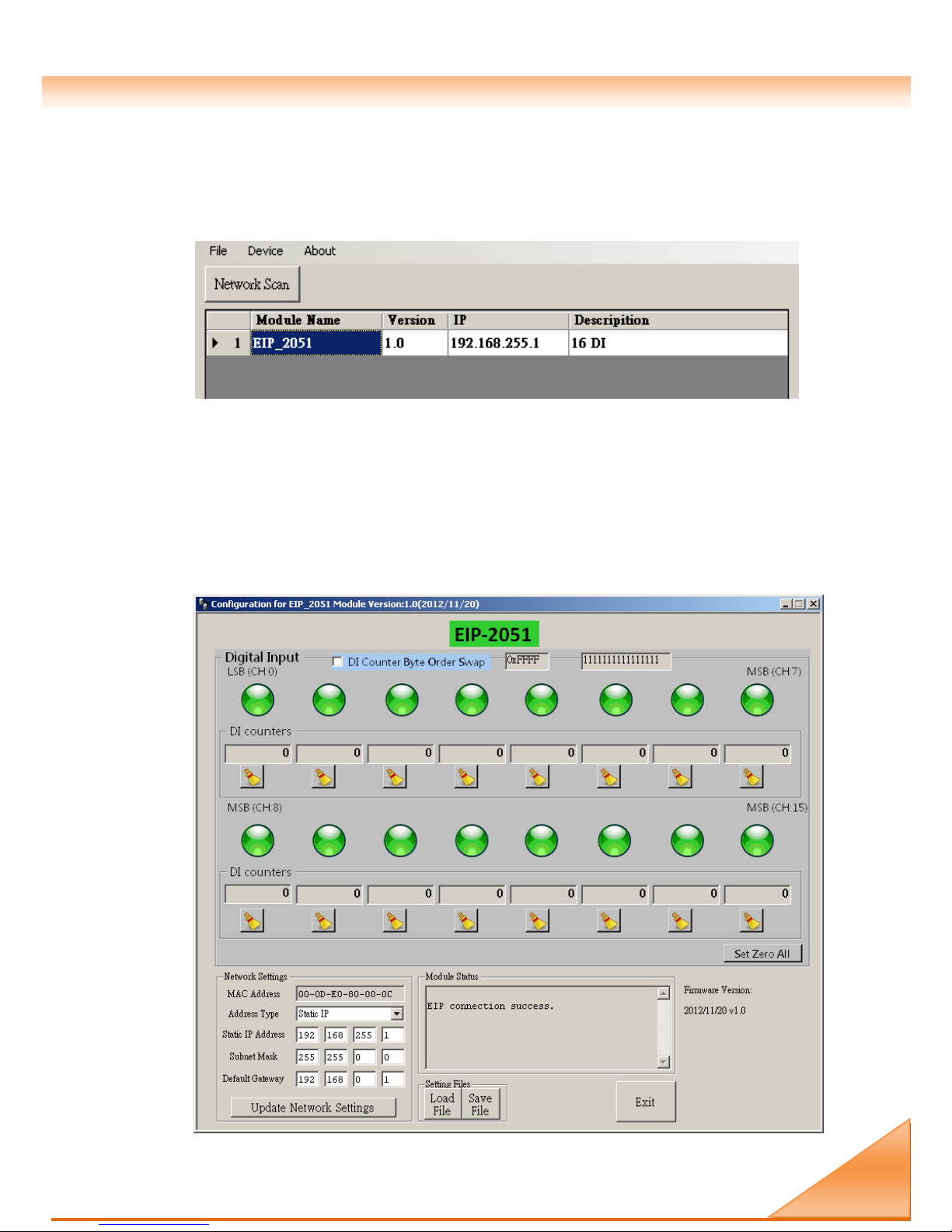
1. Double click the “EIP-2000 Utility” shortcut on the desktop.
2. Click the “Network Scan” button to search your EIP-2000 modules.
3. Click the EIP-2051 or other EIP-2000 modules on the device list below to open the
configuration dialog of EIP-2000. Each EIP-2000 module has its own configuration
interface.
4. You can observe the DI status with the green circles which is showed on the Digital Input
field.
4
Using the EIP-2000 Utility
Page 5
EIP-2051 Quick Start Guide
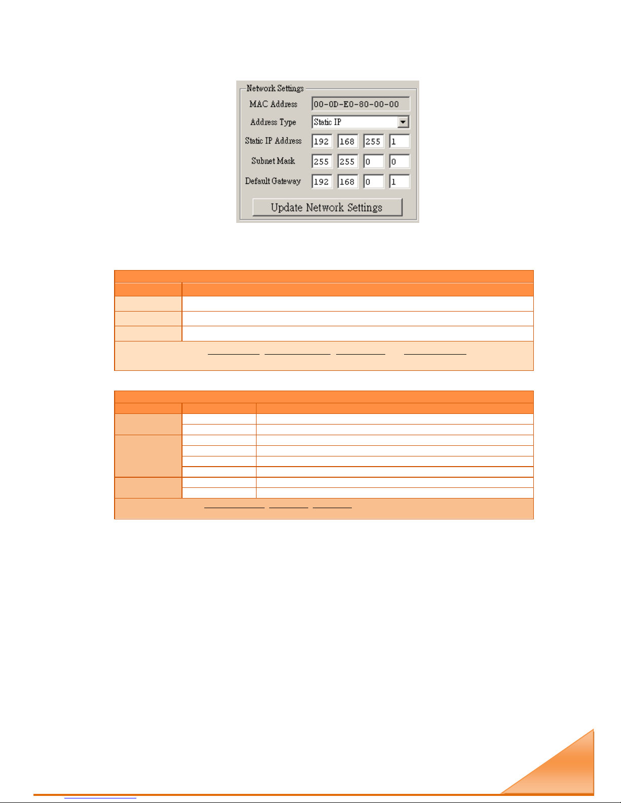
5. If the network settings have been changed, please click the “Update Network Settings”
button to update the configuration and reboot the module.
6. Configuration settings of EIP-2000
Network Settings
Item
Settings (default)
IP
192.168.255.1
Gateway
192.168.0.1
Mask
255.255.0.0
For configuration of the Address Type, Static IP Address, Subnet Mask and Default Gateway of the EIP-2000.
Please refer to section “4.2.1 Network Settings”
LED Indicator
LED
LED Status
Description
Power LED
Always On
Module is in Run mode.
Flashing
Module is in Init mode.
Status LED
Always On
EtherNet/IP connection is failed.
Blink per second
EtherNet/IP connection is successful.
Blink per 300 ms
EtherNet/IP disconnected during communication but still in Safe-Delay time.
Blink per 100 ms
Module is about to reboot.
I/O status LED
On
The DI is activated.
Off
The DI is inactivated.
For configuration of the Power On Value, Safe Value, Safe Delay for the EIP-2000. Please refer to section “4.2.2
Digital Settings”
Page 6
EIP-2051 Quick Start Guide
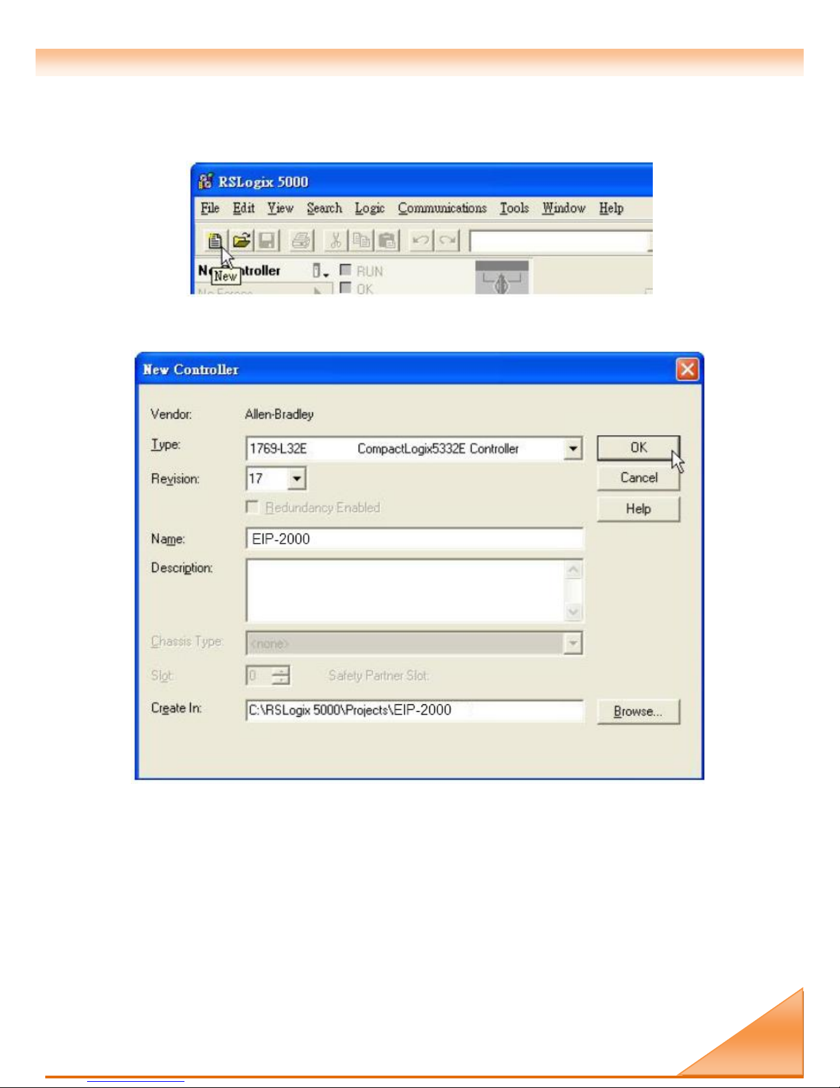
1. Open RSLogix 5000 and create a new project.
Figure5-1. Create a new project.
2. Select the PLC type and give the project a name.
Figure5-2. Set the PLC type and project name.
5
How to connect with Allen-Bradley PLC?
Page 7
EIP-2051 Quick Start Guide
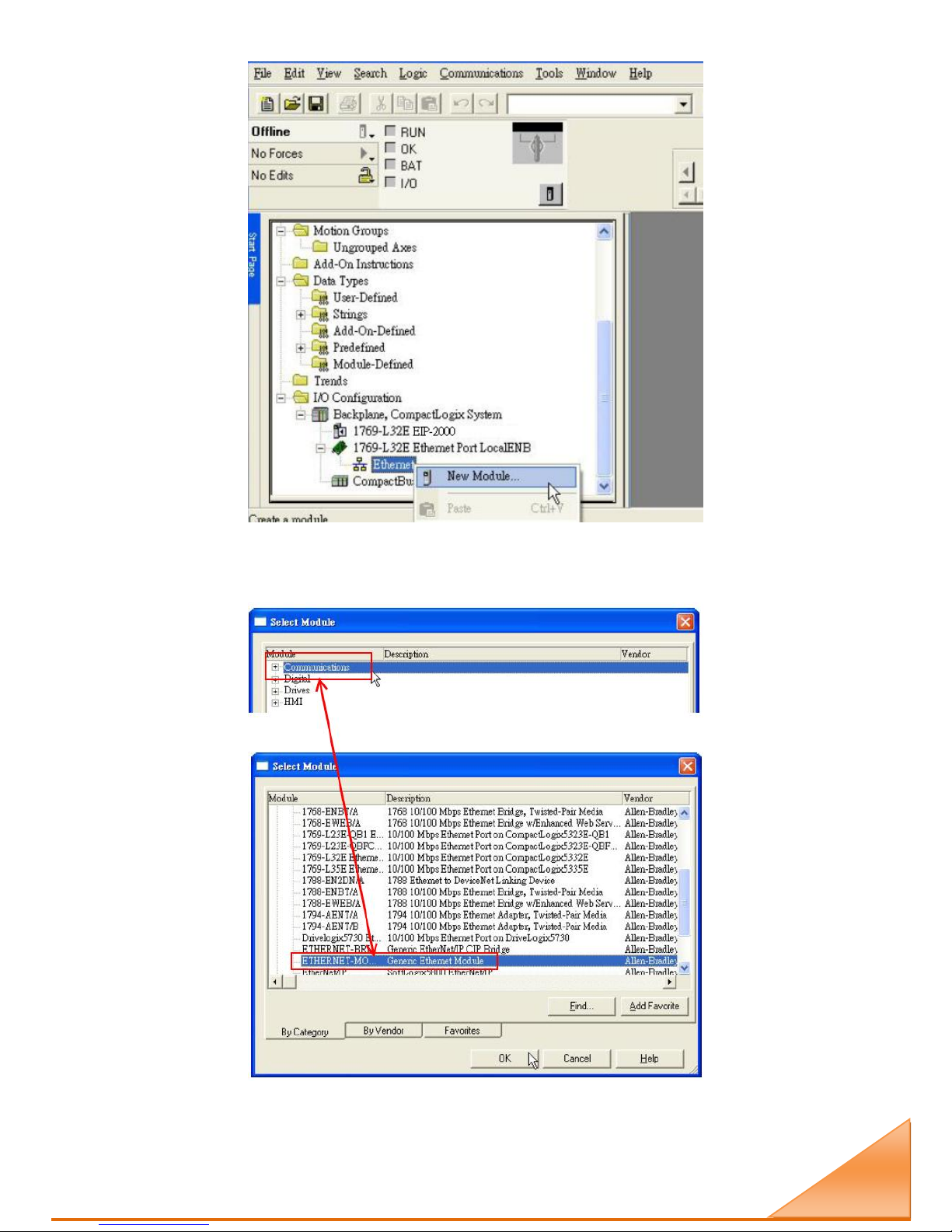
3. Create a new module in the “Ethernet” item.
Figure 5-3. Create a new module.
4. Select the “ETHERNET-MODULE” below “Communications” in the Select Module
window.
Figure5-4. Select “ETHERNET-MODULE”.
Page 8

EIP-2051 Quick Start Guide
5. Configure the new module parameters. The I/O length of new module must be the same with
the length of EIP-2051 I/O data(Table 5-1). The input data size is 66 bytes and output data
size is 2 bytes. The instance ID please refer to Table 5-2.
Figure5-5. The settings of EIP-2051 module
Table 5-1. Data Assembly of EIP-2051
Data
Assembly
Byte count
Description
Input
Assembly
66
1st Byte: DI status(DI0~DI7).
2nd Byte: DI status(DI8~DI15).
3rd~65th Byte: DI counters.
Output
Assembly
2
1st Byte: to set DI counters zero (DI0~DI7).
2nd Byte: to set DI counters zero (DI8~DI15).
Table 5-2. Instance ID table of EIP-2000
Implicit Message Information of EIP-2000
Instance
Instance ID
Data length
Input(T->O)
65
hex
(101)
Depends on modules. e.g.66
Out(O->T)
66
hex
(102)
Depends on modules. e.g.2
Configuration
64
hex
(100)
 Loading...