

ICPDAS DL-301, DL-303, DL-302 User Manual
DL301/DL302/DL303
CO/ CO2/Temperature/Humidity/Dew Point
Data Logger User Manual
Version: 1.1.0
Date: Aug. 2015
Edited by Sunny Chiu

Warranty
All products manufactured by ICP DAS are warranted against defective materials for a
period of one year from the date of delivery to the original purchaser.
Warning
ICP DAS assumes no liability for damages consequent to the use of this product.
ICP DAS reserves the right to change this manual at any time without notice. The
information furnished by ICP DAS is believed to be accurate and reliable. However, no
responsibility is assumed by ICP DAS for its use, nor for any infringements of patent s or
other rights of third parties resulting from its use.
Copyright
Copyright © 2015 by ICP DAS. All rights are reserved.
Contact Us
If you have any questions, please feel free to contact us via email at:
Service@icpdas.com
Service.icpdas@gmail.com

Contents
1. Introduction................................................................................................................1
2. Hardware ...................................................................................................................6
2.1 Specifications....................................................................................................6
2.2 Appearance .......................................................................................................8
2.3 Dimensions (unit: mm)....................................................................................12
2.4 Cabling for Power and Network ......................................................................13
3. Configuration via Touch Screen ...............................................................................15
3.1 Alarm &T emperature.......................................................................................17
3.2 DO & LCD.......................................................................................................19
3.3 Date & Time....................................................................................................21
3.4 Data Logger....................................................................................................22
3.5 Ethernet ..........................................................................................................23
3.6 RS-485............................................................................................................25
4. Configuration via Web Browser................................................................................26
4.1 Search the DL-300 logger...............................................................................26
4.2 Logging into the DL-300..................................................................................27
4.3 Home..............................................................................................................28
4.4 Network...........................................................................................................30
4.5 MQTT..............................................................................................................32
4.6 I/O Settings.....................................................................................................36
4.7 Message.........................................................................................................41
4.8 Accessible IP...................................................................................................43
4.9 Change Password...........................................................................................44
4.10 Logout...........................................................................................................46
5. Configuration via RS-485.........................................................................................47
6. Monitoring via Mobile Devices .................................................................................56
7. Utility to Get/Manage Data Log................................................................................57
8. FAQ..........................................................................................................................68
Q1: What is ABC (Automatic Baseline Correction)?..............................................68
Q2: Why I need to enable the ABC?.....................................................................68
Q3: Does the DL-302/DL-303 enable the ABC as the factory default setting?......68
Q4: What to do when the ABC is no work?...........................................................68
Q5: How to set the touch password?....................................................................69
Q6: How to cancel the touch password?...............................................................70
Q7: How to set the Accessible IP?........................................................................70

Q8: How to delete the Accessible IP settings?......................................................71
Q9: How to clear the data logged in a DL-300 module? .......................................71
Q10: How to calibrate the touch screen?..............................................................72
Q11: How to download firmware into a DL-300 module?......................................73
Q12: How to display message on the DL-300 with Modbus command?...............75
Appendix A: DCON Command Sets.............................................................................78
A-1. DL-301 DCON Command Sets .....................................................................78
A-2. DL-302 DCON Command Sets .....................................................................84
A-3. DL-303 DCON Command Sets .....................................................................90
Appendix B: ModbusMasterToolPC .............................................................................96
Appendix C: Modbus Address Table ..........................................................................100
C-1. DL-301 Modbus Address Mappings (Base 1)..............................................100
C-2. DL-302 Modbus Address Mappings (Base 1)..............................................107
C-3. DL-303 Modbus Address Mappings (Base 1)..............................................113
Revision History.........................................................................................................120
DL-300 Data Logger User Manual Version 1.1.0 Aug. 2015 - 1 -
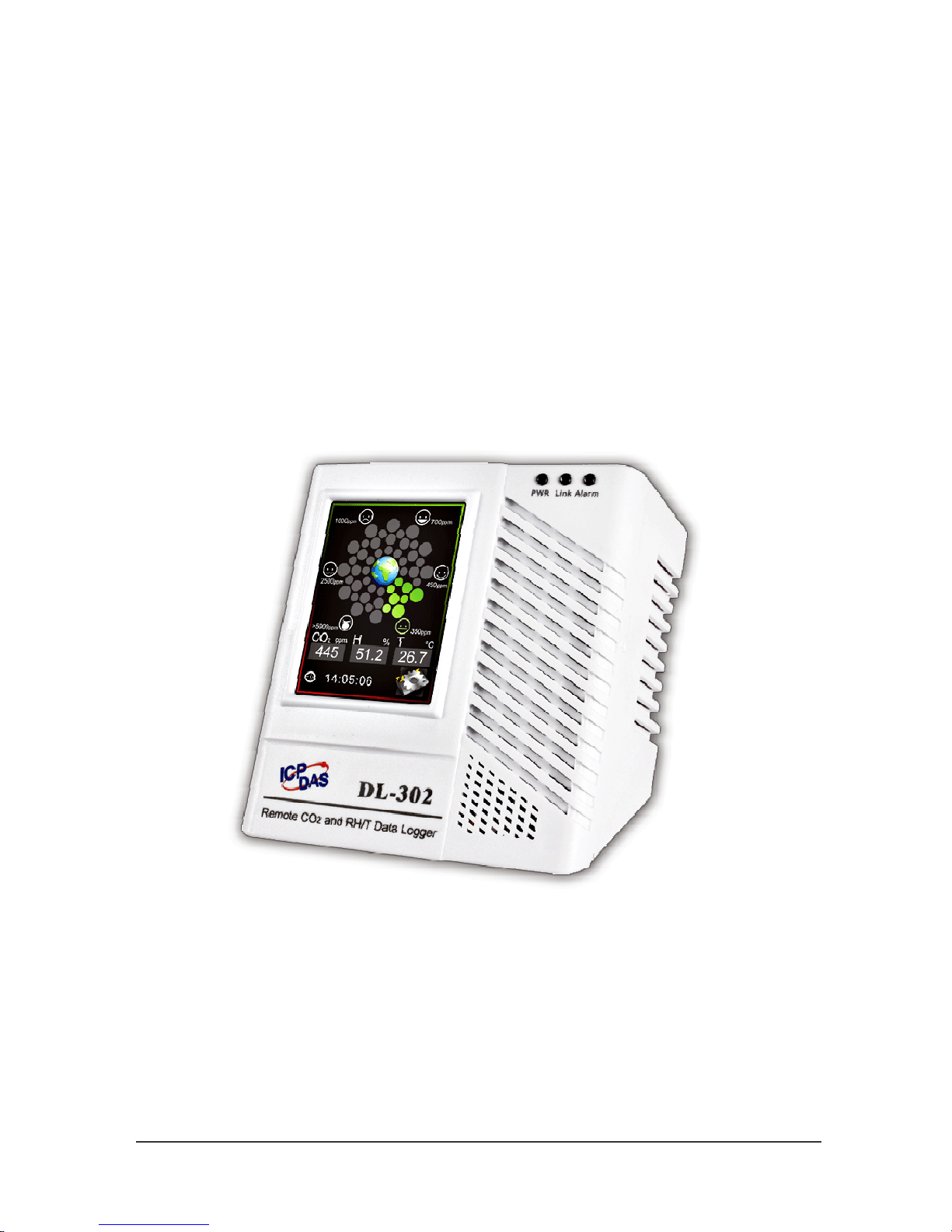
1. Introduction
The DL-300 series is a data logger designed to accurately measure and record the
concentration of carbon monoxide/carbon dioxide in the atmosphere, temperature and
humidity. It can display the real-time data and log the concentration of CO, CO2,
temperature and humidity with a date and time stamp for downloading later. The logging
interval is programmable and up to 450,000 data points can be stored in built-in,
non-volatile memory.
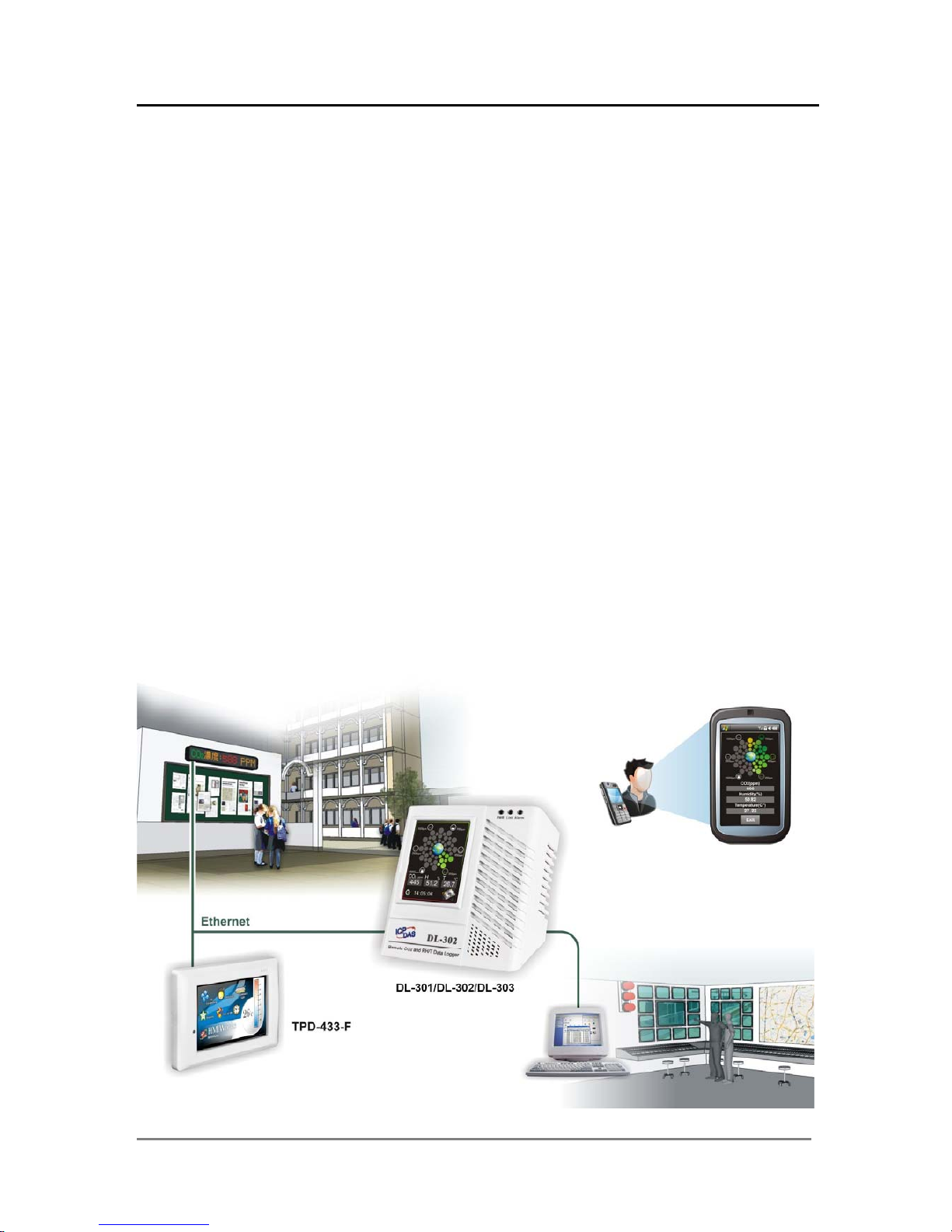
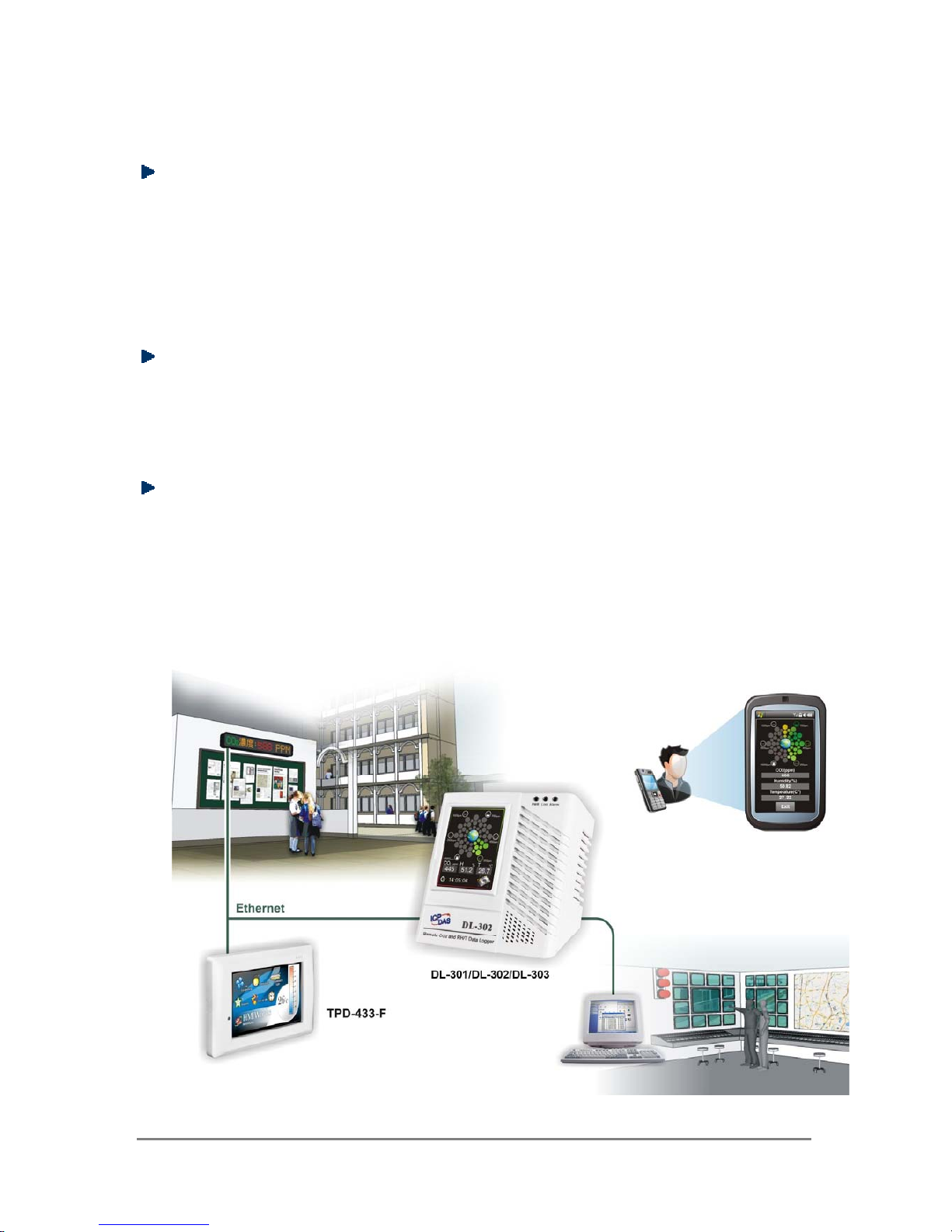
Users can configure a DL-300 module from the touch screen or via a regular web
browser when the module and PC are both connected to the same switch or Ethernet
segment. With free iAir app on users’ iOS or Android phones or tablets, they can get the
real data over a Wi-Fi network anytime and anywhere. The free DL300 Utility is a
convenient software tool to get the real-time data, show run charts and download data
from multiple devices running on Windows platform.
The DL-300 series contains RS-485, Ethernet and PoE communication interfaces, the
most common communication interfaces in industrial network. It supports a wide
operating temperature range of 0 ~ 50°C and easy to be installed by placing on a
horizontal surface such as a desktop, mounted on a DIN-rail, or mounted on the wall.

DL-300 Data Logger User Manual Version 1.1.0 Aug. 2015 - 2 -
Characteristics
Simultaneous display for CO/CO2 level, temperature, humidity and dew point
CO measurement range: 0 ~ 1000 ppm
CO2 measurement range: 0 ~ 9999 ppm
Nondispersive Infrared (NDIR) sensor with Automatic Baseline Correction
algorithm for CO
2
measurement
Able to store up to 450,000 records
2.8" LCD touch screen with resolution of 240 x 320 x 16
Supports displaying multilingual messages
Remote control with a standard web-browser
iAir App for iOS or Android mobile devices to monitor on-line data
Supports the DCON, Modbus RTU, Modbus TCP and MQTT protocols
One relay output for turning on/off alarm light/buzzer or IAQ control devices
Includes RS-485/Ethernet/PoE communication interfaces
Desktop, DIN-Rail or wall mounting
Wide operating temperature range of 0 ~ 50°C
RoHS compliant with no Halogen
DL-300 Data Logger User Manual Version 1.1.0 Aug. 2015 - 3 -
Features
NDIR Sensor
NDIR (Non-Dispersion Infrared) is based on one of the natural properties of CO2
molecules: CO2 molecules absorb light at a specific wavelength of 4.26 µm. This
wavelength is in the infrared (IR) range. High concentrations of CO2 molecules
absorb more light than low concentrations. NDIR sensor can detect fast and
accurately in a wide range of CO2 concentration.
Built-in Web Server
With the built-in Web server, users can easily log in to the DL-300 module via a
standard web browser to monitor the data and configure the settings without install
any software in the terminal.
Get Real-time Data Anywhere and Anytime
iAir App for iOS or Android Phones or Tablets is free and easy to install, it can
obtain the real-time data from DL-300 modules over a Wi-Fi network anytime and
anywhere. The iAir App can link to the DL-300 modules by specifying IP addresses
or by searching all the modules connected to the same Ethernet segment.
DL-300 Data Logger User Manual Version 1.1.0 Aug. 2015 - 4 -
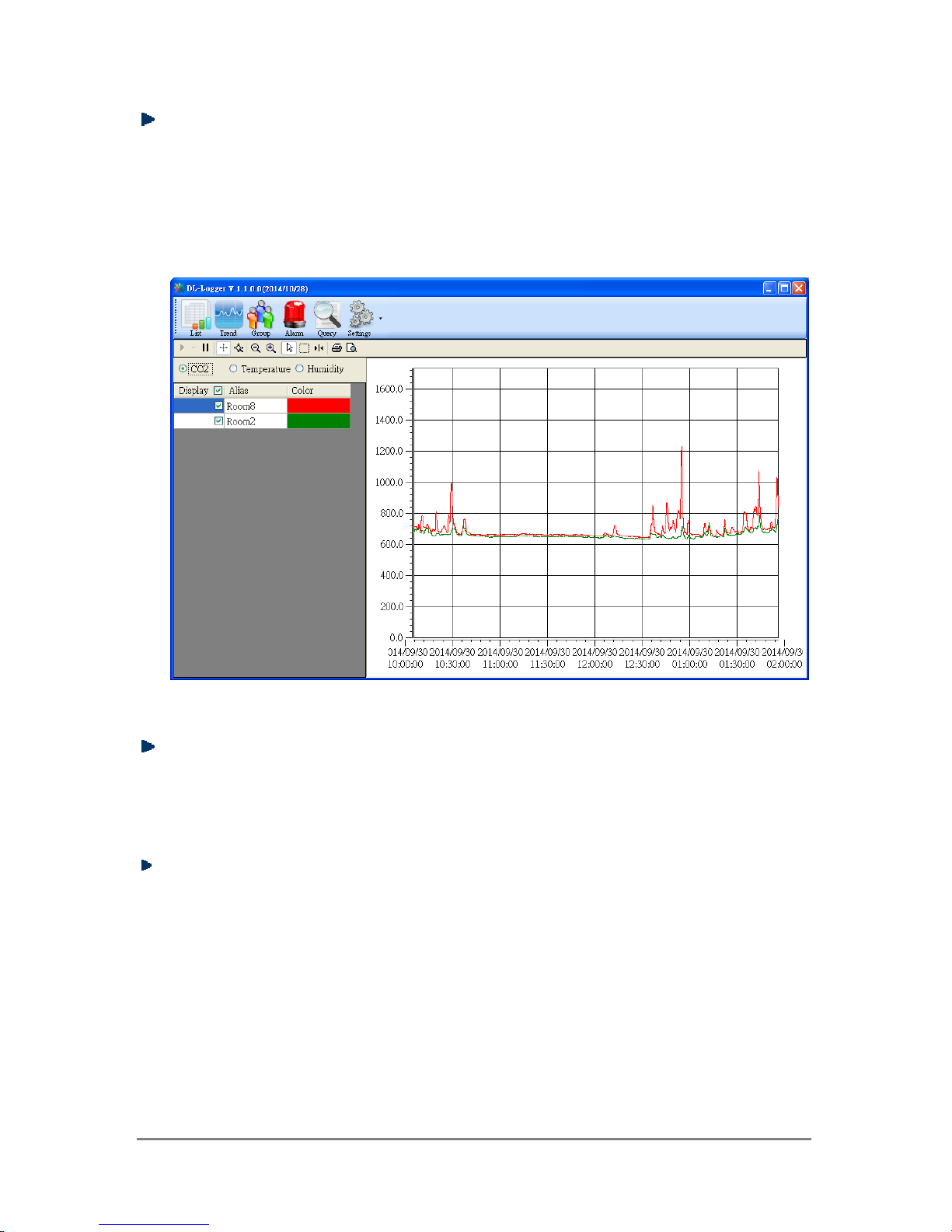
Data Logging Software
The DL300 Utility can be used to configure the modules, monitor real-time data and
show the run chart, log alarm events, group DL-300 modules so that the status of
distribution groups can be viewed and managed. The utility also allows the log data
to be downloaded and exported to a .CSV file that can then be imported into any
industry-standard software or spread sheet for analysis.
Easy integration with SCADA software
Modbus is one of the most popular protocols used in the industrial world.
Supporting traditional serial protocols of RS-485 and Ethernet protocols allow the
DL-300 series well-integrated into the HMI/SCADA systems.
Alarm
DL-300 series allows users to set high alarm level for CO/CO2/
Temperature/Humidity/Dew Point and low alarm level for
Temperature/Humidity/Dew Point, and to enable/disable the alarm functions. An
Alarm LED indicator on the front of the DL-300 module will flash when an alarm
event is activated, and a relay output related to all alarm events can be use to tap
an alarm light/sound or control the IAQ devices such as ventilators, air cleaners,
and filters. Beep alarm is available when the CO/CO2 high level alarm occurs.
.
DL-300 Data Logger User Manual Version 1.1.0 Aug. 2015 - 5 -
Screen Lock
Users can secure a DL-300 module by setting a screen lock via the web interface. If
the lock is set, users need to enter the correct password when they would like to
configure the DL-300 module.
Automatic Baseline Correction
The built-in ABC algorithm makes the CO2 sensor on the DL-302 and DL-303
maintenance-free. In most indoor applications, the carbon dioxide level drops to
nearly outside air - 400 ppm, and then the ABC algorithm constantly keeps track of
the lowest reading and slowly corrects it as the expected fresh air value of 400
ppm.
The ABC algorithm can not apply for the places where are no periods that the CO
2
concentration drops to background level such as greenhouses, hospitals, 24-hour
operation factories or stories. The ABC function needs be disabled where the
spaces the CO
2
concentration may be elevated at all times.
Easy Wiring
Support for RS-485, Ethernet and Power over Ethernet (PoE) interfaces for users
to choose the appropriate one to meet the field requirements.
Power over Ethernet (PoE)
The DL-300 series features true IEEE802.3af-compliant (classification, Class 1)
PoE technology that allows both power and data to be carried over a single
Ethernet cable. PoE provides a unified power system, as well as backup provisions
for critical building functions, without any additional cables, outlets or connections.
It can reduce the power supply wiring and maintenance costs, and improve system
scalability.
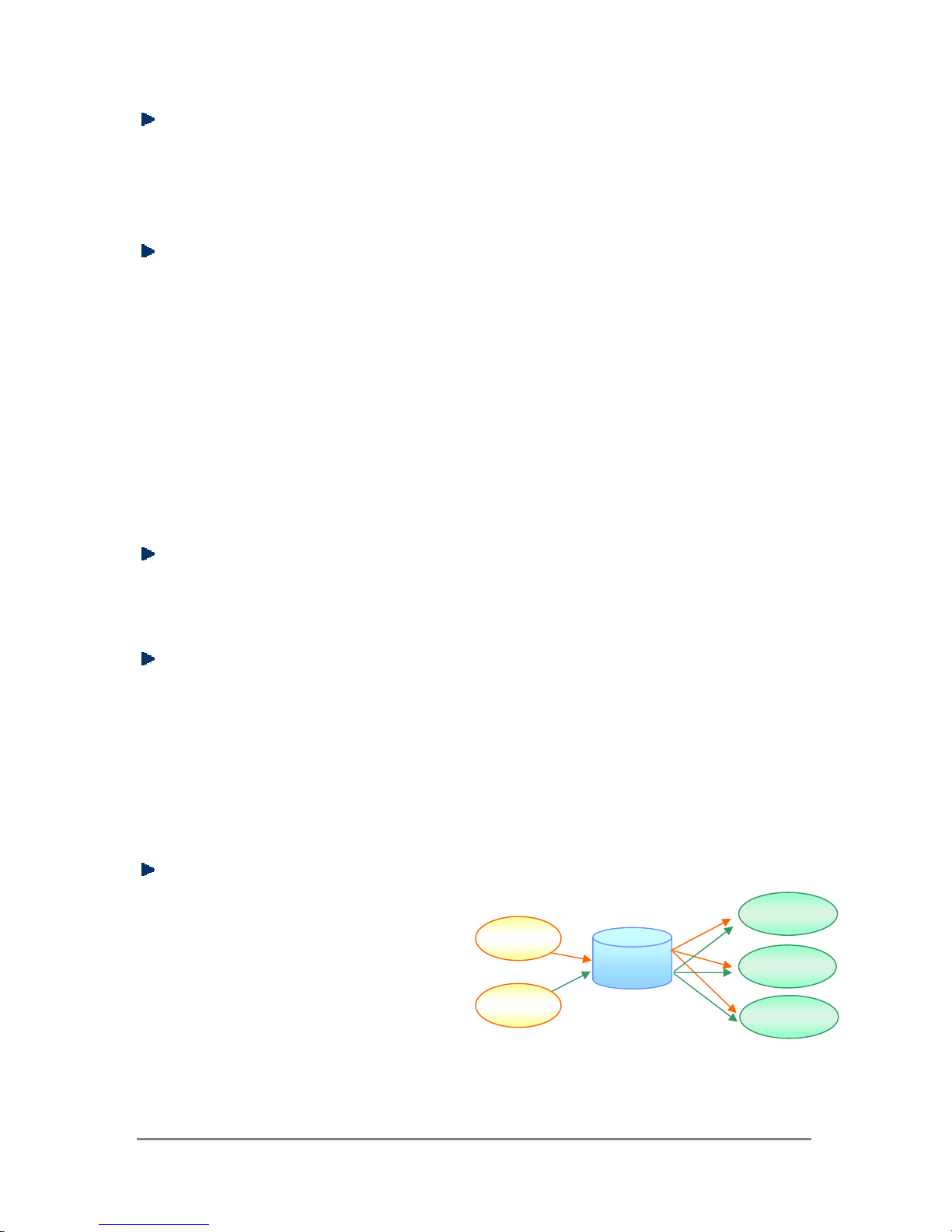
Support for MQTT protocol
MQTT is a protocol designed for the
efficient exchange of real-time data
with sensor and mobile devices. It
runs over TCP/IP and is in widest
use on the "machine-to-machine"
(M2M) and "Internet of Things"
applications today
Smartphone
MQTT
Broker
DL-301
DL-302
Mobile Tablet
Subscriber
DL-300 Data Logger User Manual Version 1.1.0 Aug. 2015 - 6 -
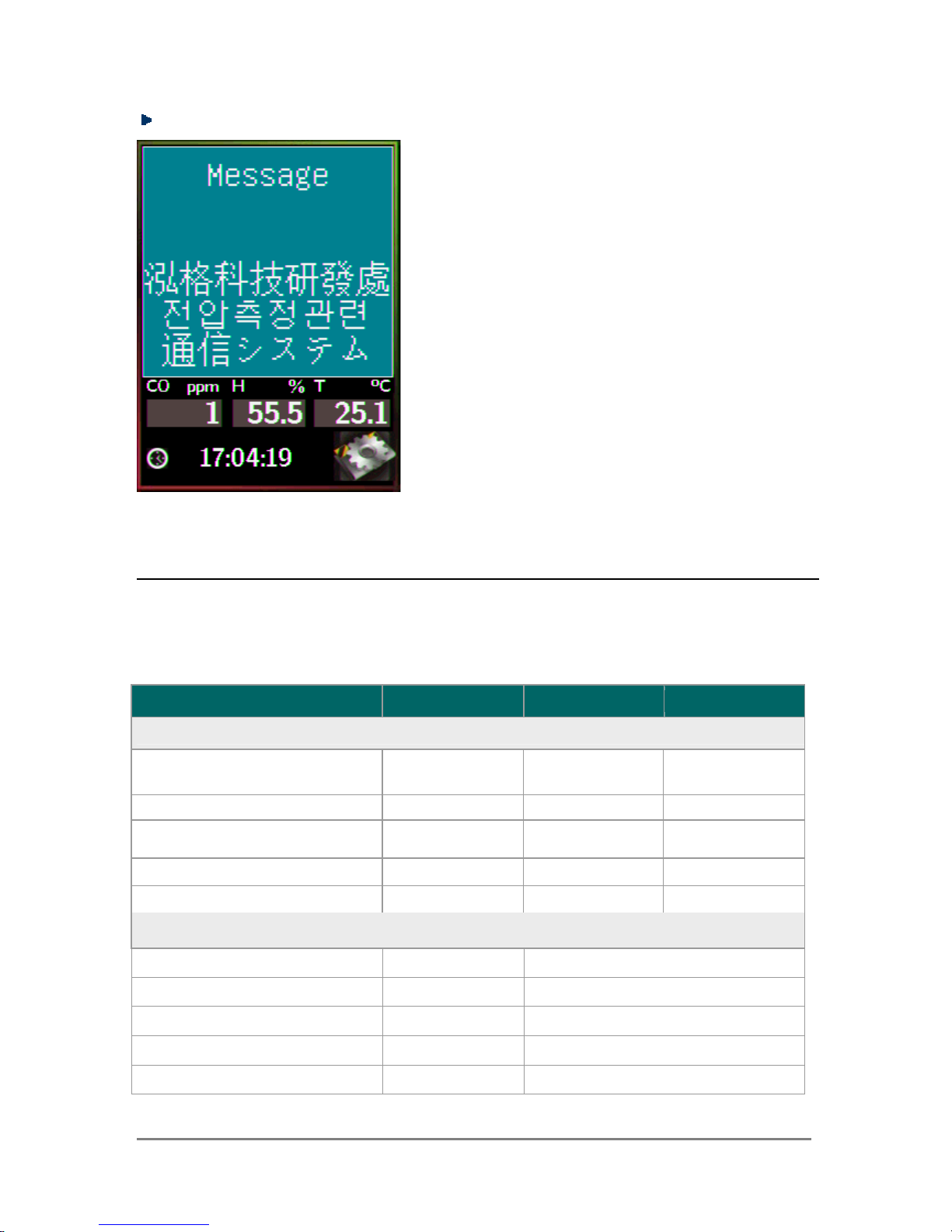
Display Multilingual Messages on Screen
2. Hardware
2.1 Specifications
Model DL-301 DL-302 DL-303
CO Measurement
Range
0 to 1000 ppm
(Electrochemical)
-
0 to 1000 ppm
(Electrochemical)
Resolution
1 ppm
-
1 ppm
Accuracy
±5% of measured
value
-
±5% of measured
value
Response Time
30 seconds
-
30 seconds
Warm-up Time
60 seconds
-
60 seconds
CO2 Measurement
Range
-
0 ~ 9999 ppm
Resolution
-
1 ppm
Accuracy
-
±30 ppm ±3%
Response Time
-
20 seconds
Warm-up Time
-
60 seconds
The display message function supports
multilingual character sets in UTF-8 encoding.
Users can remotely display pre-saved
messages or dynamic messages by Modbus
commands, or send a dynamic message
through the web interface.
A message is limited to six lines maximum and
14 half-width characters or 7 full-width
characters maximum each line.
DL-300 Data Logger User Manual Version 1.1.0 Aug. 2015 - 7 -
Temperature Measurement
Range -10 ~ +50°C
Resolution 0.1°C
Accuracy ±0.6°C
Relative Humidity Measurement
Range 0 ~ 100% RH, Non-condensing
Resolution 0.1% RH, Non-condensing
Accuracy ±5% RH, Non-condensing
Dew Point
Range
Calculated using temperature and relative humidity
Resolution
0.1°C
System
CO Alarm Yes - Yes
CO2 Alarm - Yes Yes
Real Time Clock Yes
Data Logger Yes, 450,000 Records
Alarm Relay Output
Form A×1, SPST. 30 VDC @ 16 A or 250 VAC @ 16 A
30 VDC @ 16 A or 250 VAC @ 16 A
Network Interface RS-485/Ethernet/PoE
Main Machine Interface
Touch Screen
2.8” TFT (Resolution: 240 x 320 x 16),
Defective Pixels <= 3
Backlight Life 20,000 hours
Brightness 160 cd/m2
Electrical
Powered via Terminal Block +12 ~ +48 VDC
Powered via PoE IEEE 802.3af, Class 1 (require a PoE switch or injector)
PoE
1.84 W (Max.) 2.65 W (Max.) 2.83 W (Max.)
Power Consumption
Non-PoE
1.74 W (Max.) 2.14 W (Max.) 2.24 W (Max.)
Mechanical
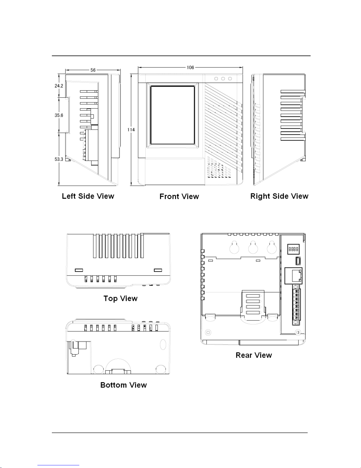
Dimensions (W x L x H) 106 mm x 114 mm x 56 mm
Installation Desktop, DIN-Rail or Wall Mounting
Environment
Operating Temperature 0 ~ +50°C
Storage Temperature -30 ~ +75°C
Humidity 10 ~ 90% RH, Non-condensing
DL-300 Data Logger User Manual Version 1.1.0 Aug. 2015 - 8 -
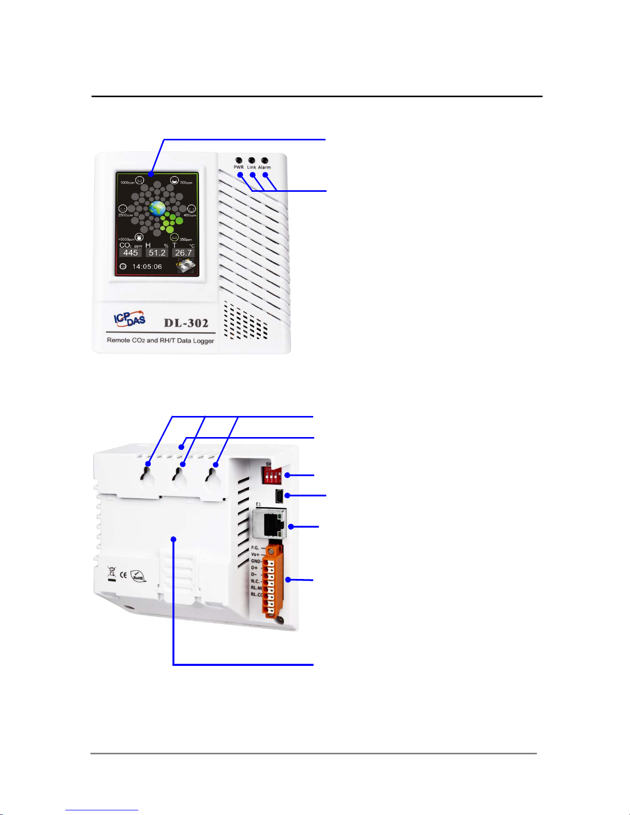
2.2 Appearance
2.8” LCD Touch Screen
LED Indicators:
Power
Ethernet Link
Alarm
DIP Switch
USB (only used to update Firmware)
PoE/Non-PoE Ethernet Port
Holes for Wall-mounting
Buzze
r
Connectors:
Power
Frame Ground
RS-485
Alarm Relay Output
DIN-Rail Mounting
DL-300 Data Logger User Manual Version 1.1.0 Aug. 2015 - 9 -
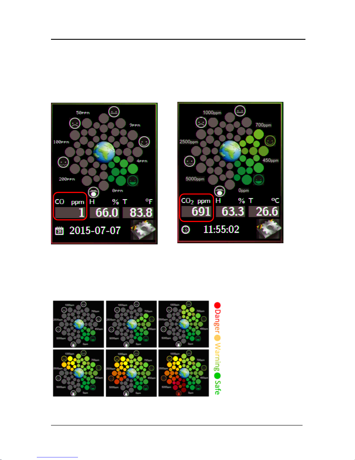
2.8” LCD Touch Screen
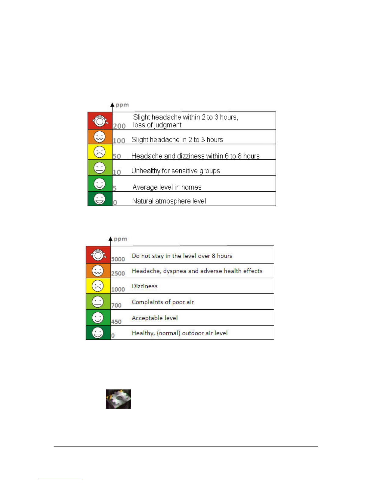
The DL-300 series is equipped with a touch screen user interface that allows
access to the configuration in the module. The center of the screen shows chart from
green to red to represent the concentration of CO/CO2 from low to high:
For CO
For CO
2
The CO/CO
2
concentration, temperature, humidity, dew point, alias name, date and
time are displayed in turn on the bottom left-hand side of the screen.
Touch the icon
at the bottom-right corner of the screen to enter the Settings
menu.
DL-300 Data Logger User Manual Version 1.1.0 Aug. 2015 - 10 -
LED Indicators
The three LED indicators from left to right are:
PWR: green for normal operation.
The PWR LED indicator flashes when the module is searched in the list of
iAir App and the icon is tapped for easier checking which module
is the one in the list.
Link: green for the Ethernet linked.
Alarm: red for alarm condition.
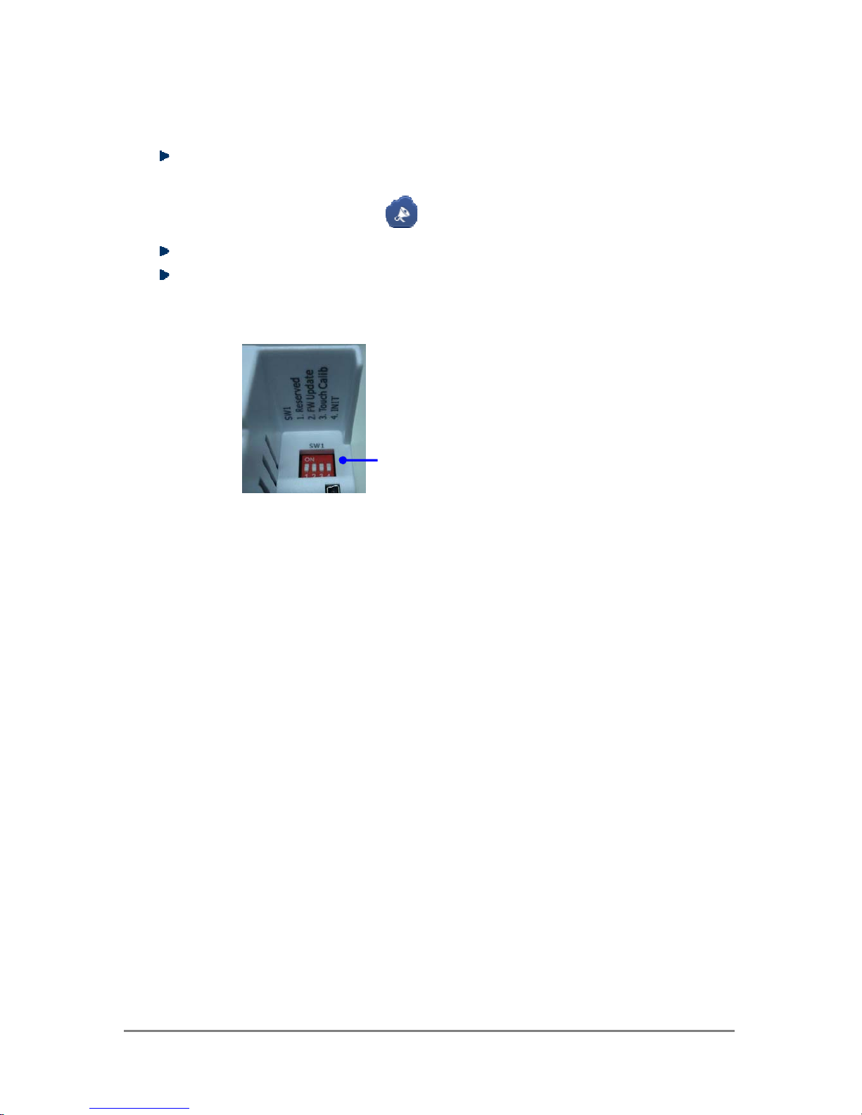
DIP Switch
USB
The USB port is used to update firmware only.
PoE/ non-PoE Ethernet port
The Ethernet port can be used to connect to a PoE switch or a non-PoE switch.
The functions are printed on the top beside the
SW1 DIP switch. All the 4 dip swit ches need be
turned to the off position for normal operation.
1. Reserved
2. FW Update: ON for updating firmware.
3. Touch Calib: ON for touch screen calibration.
4. INIT: ON for using the factory default settings
for communication
DL-300 Data Logger User Manual Version 1.1.0 Aug. 2015 - 11 -
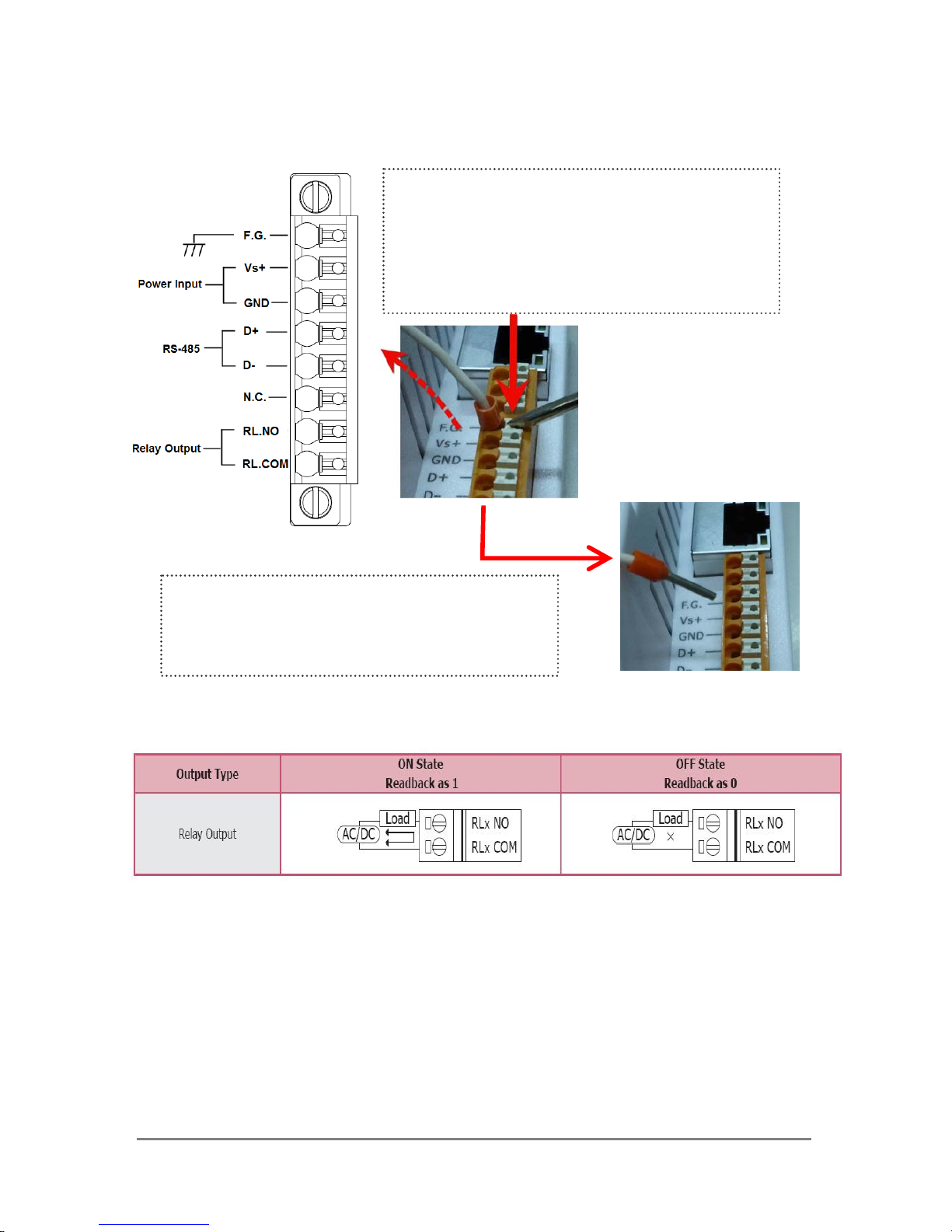
Connector for Power/ Frame Ground / RS-485/ Alarm Relay Output
Relay Output Wire Connection
The Push-in connector can easily connect and
detach solid wires or wires with wire-end
ferrules without using tools. Just push in the
solid wire to lock it and press the white button to
release the wire.
Wire requirement:
y Stripping length: 8 ~ 10 mm
y 0.20 - 1.5 mm² (IEC) / 28 - 16 AWG (UL)
DL-300 Data Logger User Manual Version 1.1.0 Aug. 2015 - 12 -
2.3 Dimensions (unit: mm)
DL-300 Data Logger User Manual Version 1.1.0 Aug. 2015 - 13 -
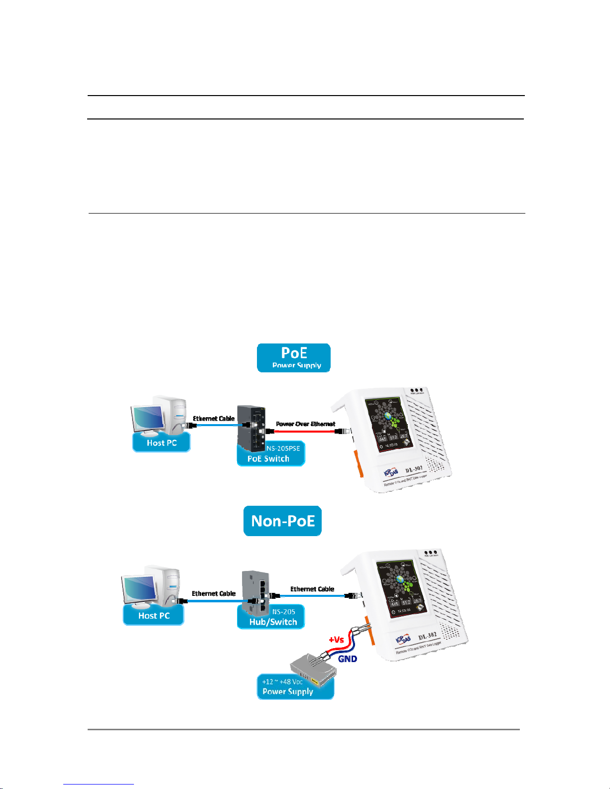
2.4 Cabling for Power and Network
Note
y Do not install the DL-300 module near a vent, a ventilation fan or a door where the
air flows faster. Also avoid putting the module on a desktop below the nose and
mouth to prevent incorrect measurement.
y Avoid installing in locations where the temperature is below 0°C or above 50°C.
y Avoid installing in locations near a strong electromagnetic field.
For connecting with a PC or a Android device
The DL-300 logger can connect to a PoE network without a power source or connect
to a non-PoE network. When using the Search function in iAir App on Android or iOS
mobile devices, mobile devices need to connect to the same subnet that the DL-300
connected to over Wi-Fi. Similarly to using the Search function in DL-300 Utility
running on Windows, the module and the host PC need to connect on the same
subnet, too.
DL-300 Data Logger User Manual Version 1.1.0 Aug. 2015 - 14 -
The iAir App and DL-300 Utility search the logger by broadcast, therefore only the
devices on the same subnet can be searched out. It means that the host PC, Android
devices and the logger must have the same broadcast address. The broadcast address
for an IPv4 device can be obtained by performing a bitwise OR operation between the
bit complement of the subnet mask and the IP address for a device. In other words, take
the device's IP address, and set to '1' any bit positions which hold a '0' in the subnet
mask.
For example, in an entire IPv4 subnet, the host PC or the Android device uses the
private IP address space 172.16.0.0/12 and subnet mask address 255.240.0.0, the
broadcast address is 172.16.0.0 | 0.15.255.255 = 172.31.255.255. Only the loggers
which have the same broadcast address could be searched out in the iAir App or
DL-300 Utility. Please contact with your network administrator to make sure the DL-300
logger is connected to the same sub-network that your Android devices or PC is
connected to.
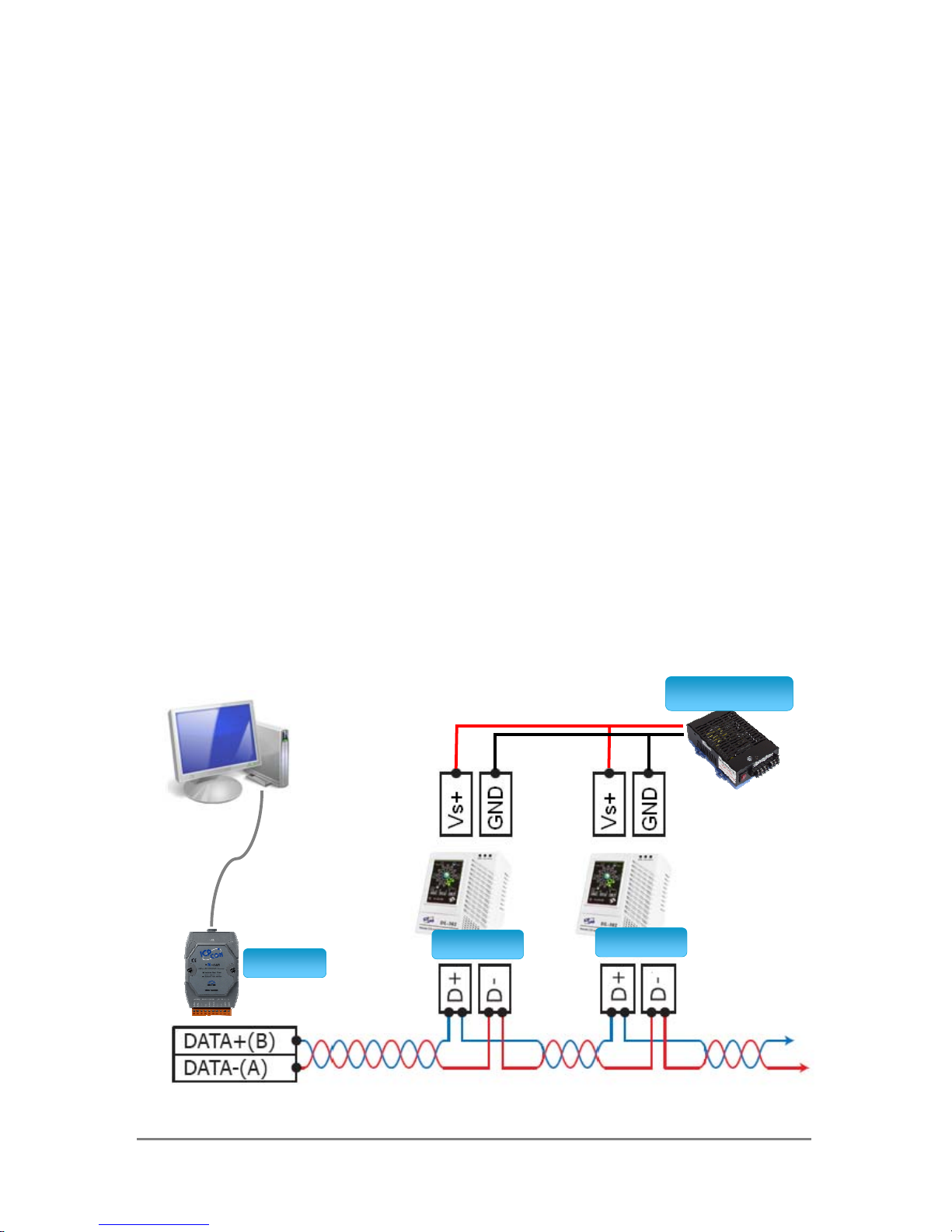
For connecting with PC via RS-485 network
The DL-300 logger can connect to the PC through a RS-485 network with power input
requirement of +12 ~ +48 VDC.
RS485Networ
k
DL302
PowerSupply
USB/RS485Converter
I7561
DL302
DL-300 Data Logger User Manual Version 1.1.0 Aug. 2015 - 15 -
3. Configuration via Touch Screen
Home screen of DL-300 logger:
CO/CO2
According to the concentration of CO/CO
2
in the air from low to high, the illustration at
the center of screen shows from green to red:
DL-300 Data Logger User Manual Version 1.1.0 Aug. 2015 - 16 -
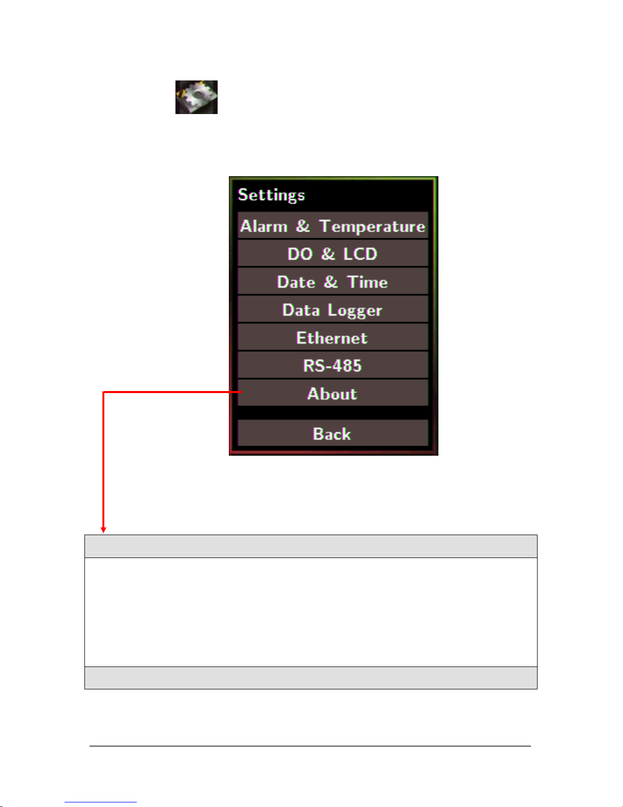
Touch the icon in the bottom-right corner of screen to enter the Settings
menu
About:Information about the unit
The information including:
- Model Name: DL-301/DL-302/DL-303
- Alias Name: The user-defined name for identifying a DL-300 more easily.
- Firmware Version: The data and version for the firmware
- IP Address: The IP address for the logger
- MAC Address: The MAC address for the logger
Back:Back to Home Screen
DL-300 Data Logger User Manual Version 1.1.0 Aug. 2015 - 17 -
Note
y The DL-300 logger comes with a resistive touch screen which senses input from
contact with nearly any object such as finger, stylus/pen or hand with gloves.
y Touching the < or > symbol beside a value can increase or decrease the value by
one. Long-pressing the < or > symbol beside a value can change the value more
quickly. Similarly touching the << or >> symbol beside a value can increase or
decrease the value by 100.
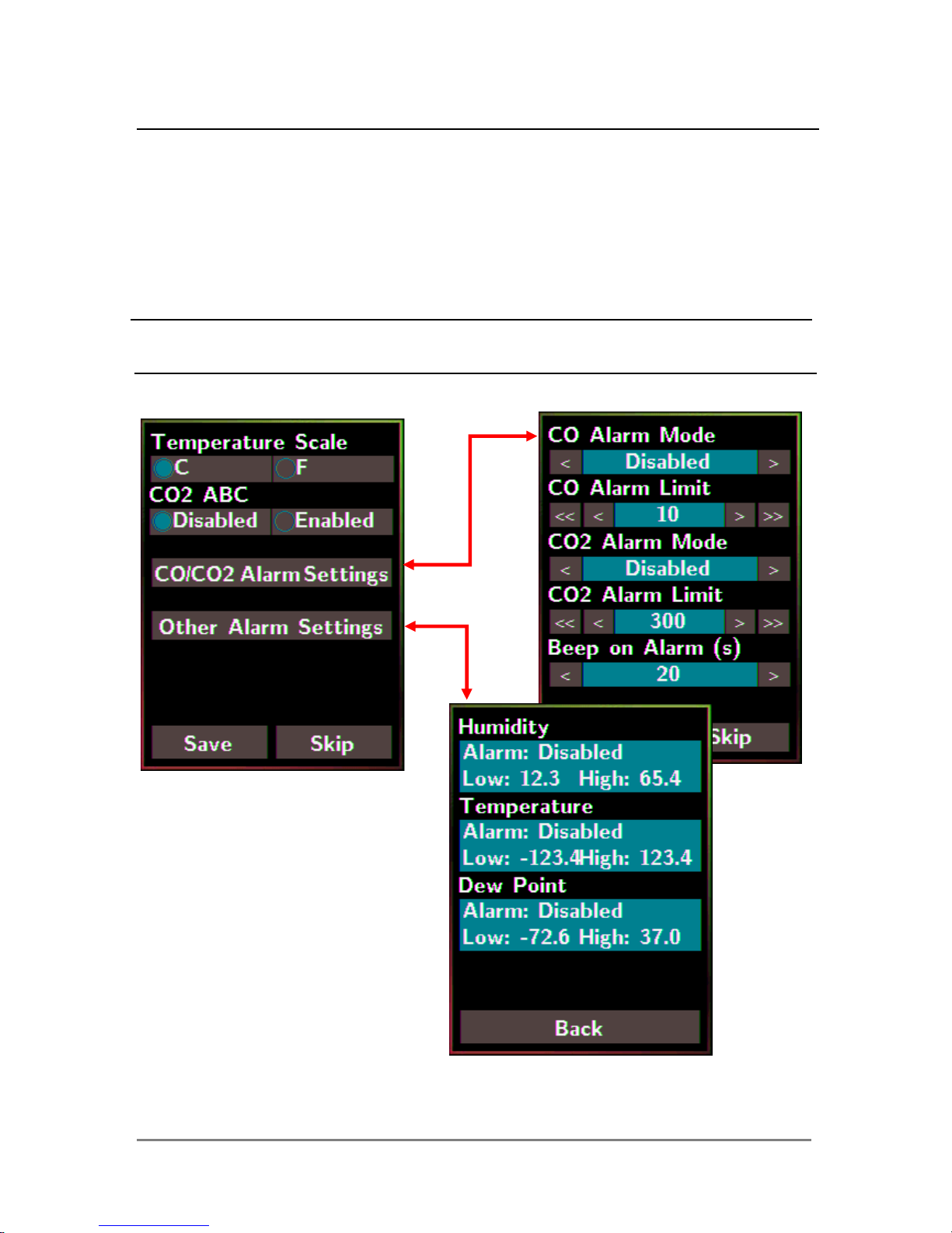
3.1 Alarm &Temperature
Tap the Alarm &Temperature item in the Settings menu to enter the sub-menu.
DL-300 Data Logger User Manual Version 1.1.0 Aug. 2015 - 18 -
Temperature Scale:
- °C (default)
- °F
CO2 ABC: (for DL-302/DL-303 only)
- Disabled: disables the CO2 ABC function (default)
- Enabled: enables the CO2 ABC function
CO/CO2 Alarm Mode:
- Disabled: disables the alarm function (default)
- Momentary:
y When the CO/CO
2
level goes higher than the value set in CO/CO2 Alarm
Limit, the Alarm LED lights red, the buzzer beeps as the setting in Beep
on Alarm(s), and the relay outputs ON signal which can be used to turn
on the user’s alarm device.
y When the CO/CO
2
level turns to lower than the value set in CO/CO2
Alarm Limit, the Alarm LED turns off; the relay outputs OFF signal.
- Latched:
y When the CO/CO
2
level goes higher than the value set in CO/CO2 Alarm
Limit, the Alarm LED lights red, the buzzer beeps as the setting in Beep
on Alarm, and the relay outputs ON signal which can be used to turn on
the user’s alarm device.
y When the CO/CO
2
level turns to lower than the value set in CO/CO2
Alarm Limit, the Alarm LED keeps red and the relay keeps ON till the
alarm status is cleared manually.
CO/CO2 Alarm Limit: Sets the high alarm level limit of CO/CO2 concentration
- CO Alarm Limit
y Default: 50 ppm
y Range: 0 ~ 1000 ppm
- CO2 Alarm Limit
y Default: 1000 ppm
y Range: 0 ~ 10000 ppm
Beep on Alarm: the alarm keeps beeping with setting for Beep on Alarm(s) in seconds.
The beep alarm is for High CO/CO2 alarm only.
- Continuously: continues beeping without stop (default)
- Disabled: disables the beep alarm
- 1~250: sets the time for beep alarm in seconds.
DL-300 Data Logger User Manual Version 1.1.0 Aug. 2015 - 19 -
Other Alarm Settings: Displays the alarm mode and high/low alarm limit settings for
Humidity , Temperature and Dew Point. Parameters on this page can be set through web
interface or Modbus/DCON commands.
- Alarm: Alarm mode, disabled by default.
- Low: low alarm limit settings
- High: high alarm limit settings
Save: Saves the modification and returns to the Settings menu.
All the changes take effect immediately after saving changes.
Skip: Returns to the Settings menu without saving any changes.
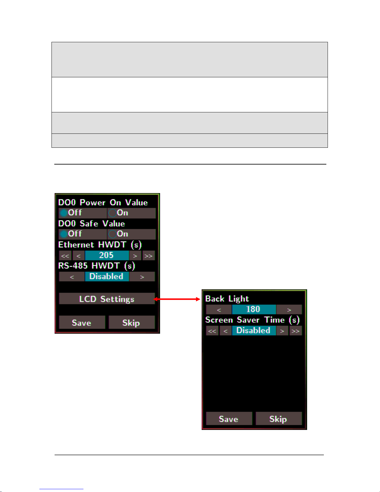
3.2 DO & LCD
Tap the DO & LCD item in the Settings menu to enter the sub-menu.
DL-300 Data Logger User Manual Version 1.1.0 Aug. 2015 - 20 -
DO0 Power On Value: Sets the relay output status when the DL-300 is powered on.
It is invalid when the any one alarm mode for CO/CO2/Humidity/Temperature/Dew
Point in Alarm &Temperature sub-menu is not disabled.
Default: Off
DO0 Safe Value: Sets the status of relay output when the Ethernet HWDT or RS-485
HWDT timeout occurs. The default setting is that a user needs to clear the timeout
status and then he can control the DO again; alternatively it can be set to control the
DO again without clear the timeout status by Modbus command. (Address: 00260)
It is invalid when the any one alarm mode for CO/CO2/Humidity/Temperature/Dew
Point in Alarm &Temperature sub-menu is not disabled.
Default: Off
Ethernet HWDT: Enables/Disables the Ethernet Host Watchdog Timer.
The Ethernet HWDT timeout will occur if the host does not visit the DL-300 through
the Ethernet network in the time period of setting for Ethernet HWDT, then the DO0
will output the safe value.
The DO0 save value is invalid when the any one alarm mode for
CO/CO2/Humidity/Temperature/Dew Point in Alarm &Temperature sub-menu is
not disabled.
y Default: Disabled
y Range: 5 ~ 65535 (unit: seconds)
RS-485 HWDT: Enables/Disables the RS-485 Host Watchdog Timer. The RS-485
HWDT timeout will occur and DO0 will output the safe value if the host does not
communicate with the DL-300 through the RS-485 network in the time period of
setting for RS-485 HWDT.
It is invalid when the any one alarm mode for CO/CO2/Humidity/Temperature/Dew
Point in Alarm &Temperature sub-menu is not disabled.
y Default: Disabled
y Range: 0.1 ~ 25.5 (unit: second)
LCD Settings: Sets the brightness of back light and the lapse time for screen saver
operation.
Backlight:
y Default: 180
y Range: 0 ~ 255
Screen Save Time (s)
y Default: 30
y Range: 0 ~ 65535 (unit: second), 0 = disables screen saver.
DL-300 Data Logger User Manual Version 1.1.0 Aug. 2015 - 21 -
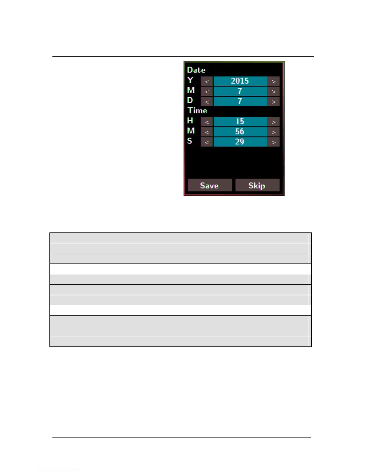
3.3 Date & Time
Tap the Date & Time item in
the Settings menu to enter the sub-menu.
Y: Sets the year from 2000 to 2159
M: Sets the month from 1 to 12
D: Sets the data from 1 to 31
H: Sets the hour from 0 to 23
M: Sets the minute from 0 to 59
S: Sets the second from 0 to 59
Save: Saves the modification and returns to the Settings menu.
All the changes take effect immediately after saving changes.
Skip: Returns to the Settings menu without saving any changes.
DL-300 Data Logger User Manual Version 1.1.0 Aug. 2015 - 22 -
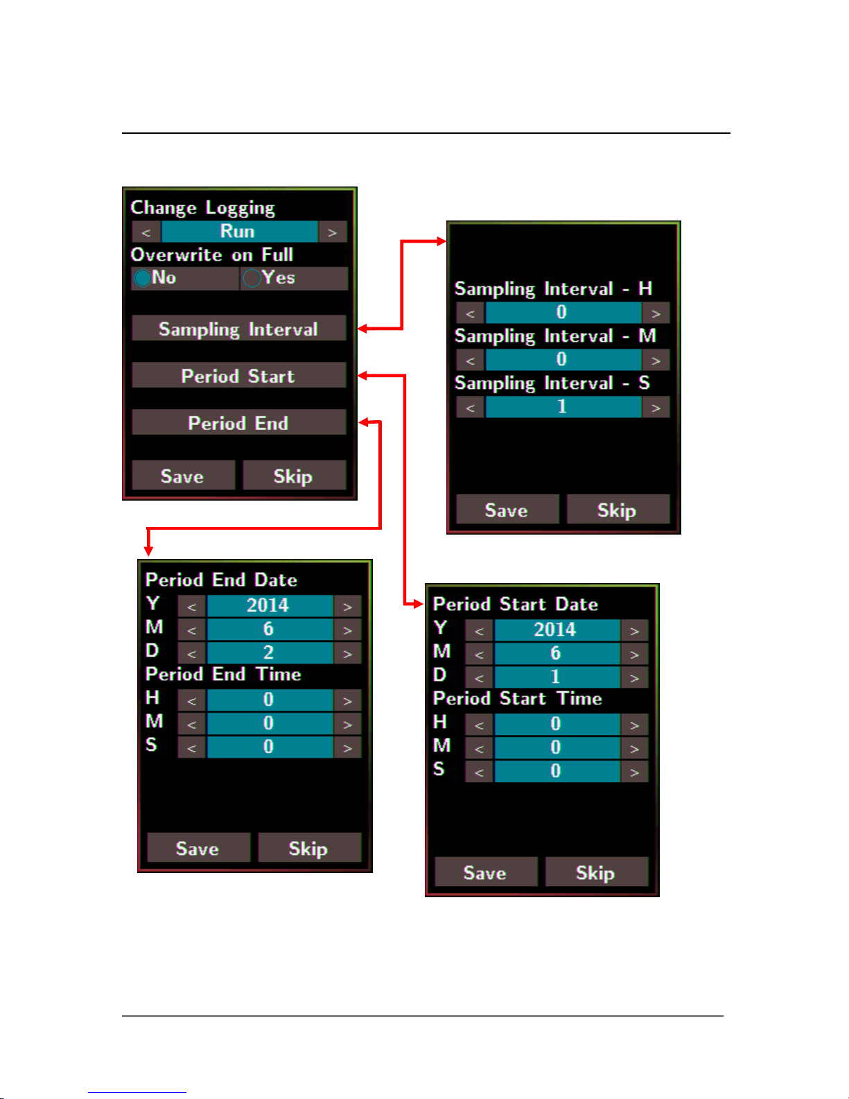
3.4 Data Logger
Tap the Data Logger item in the Settings menu to enter the sub-menu.
DL-300 Data Logger User Manual Version 1.1.0 Aug. 2015 - 23 -
Change Logging: Sets the mode for data logger
- Stop: stops logging data (default)
- Run: logs data continuously
- Period: logs data in the period of specified time
Overwrite on Full: Sets whether to overwrite old data by new ones when the memory
for data storage is full. (Over the upper limit of 450,000.)
- No: discards the new data (default)
- Yes: overwrites the old data by new ones
Sampling Interval: Sets the time interval for logging data. It is valid for both Run mode
and Period mode. Tap the Sampling Interval to enter the sub-menu.
Default: 10 (unit: seconds)
Period Start: Sets the start time for Period mode
Default: date: 2014/06/01, time: 00: 00 : 00
Period End: Sets the stop time for Period mode
Default: date: 2014/06/02, time: 00: 00 : 00
Save: Saves the modification and returns to the Settings menu.
All the changes take effect immediately after saving changes.
Skip: Returns to the Settings menu without saving any changes.
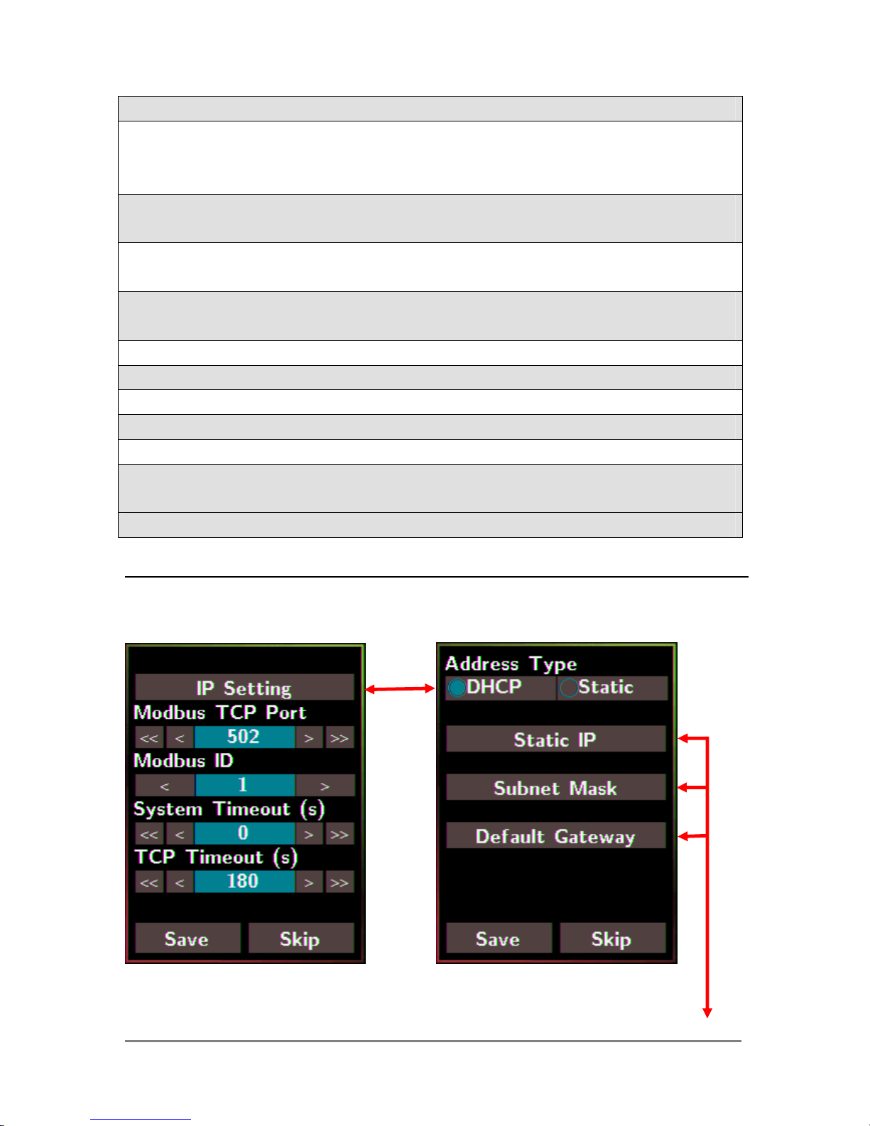
3.5 Ethernet
Tap the Ethernet item in the Settings menu to enter the sub-menu.
DL-300 Data Logger User Manual Version 1.1.0 Aug. 2015 - 24 -
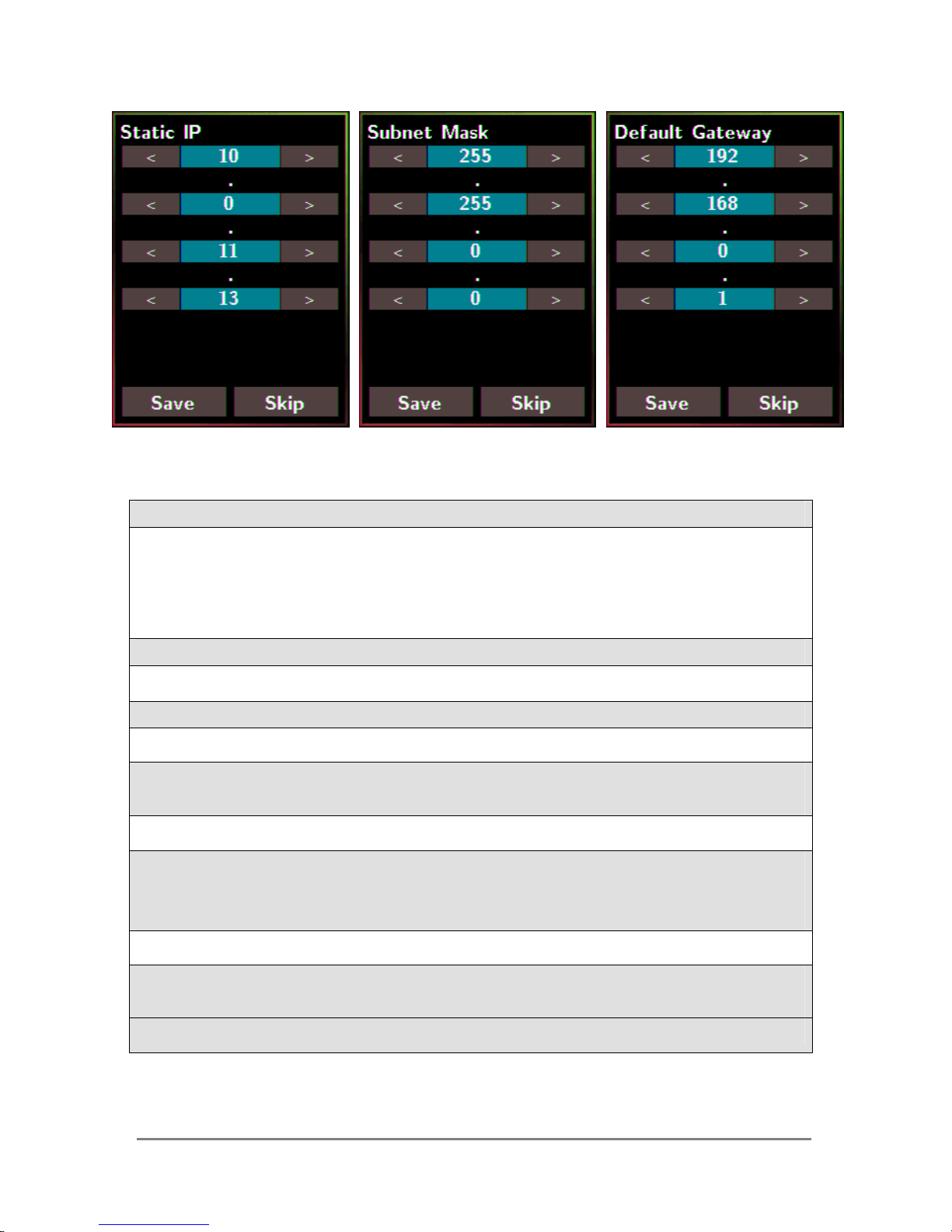
IP Setting: Taps the IP Setting item to enter the sub-menu.
Address Type: Static (default)
Static IP: 192.168.255.1 (default)
Subnet Mask: 255.255.0.0 (default)
Default Gateway: 192.168.0.1 (default)
Modbus TCP Port: Sets the port number for Modbus TCP communication
Default: 502
Modbus ID: Sets the ID for Modbus TCP communication
Default: 1
System Timeout: Sets the timeout for rebooting a DL-300 which is abnormal or failure
to communicate.
Default: 0 (unit: seconds)
TCP Timeout: Sets the timeout for TCP/IP communication. If there is no data received
from Ethernet port over the time period of setting for TCP timeout, the
established TCP/IP connections will be disconnected automatically.
Default: 180 (unit: seconds)
Save: Saves the modification and returns to the Settings menu.
All the changes take effect immediately after saving changes.
Skip: Returns to the Settings menu without saving any changes.
DL-300 Data Logger User Manual Version 1.1.0 Aug. 2015 - 25 -
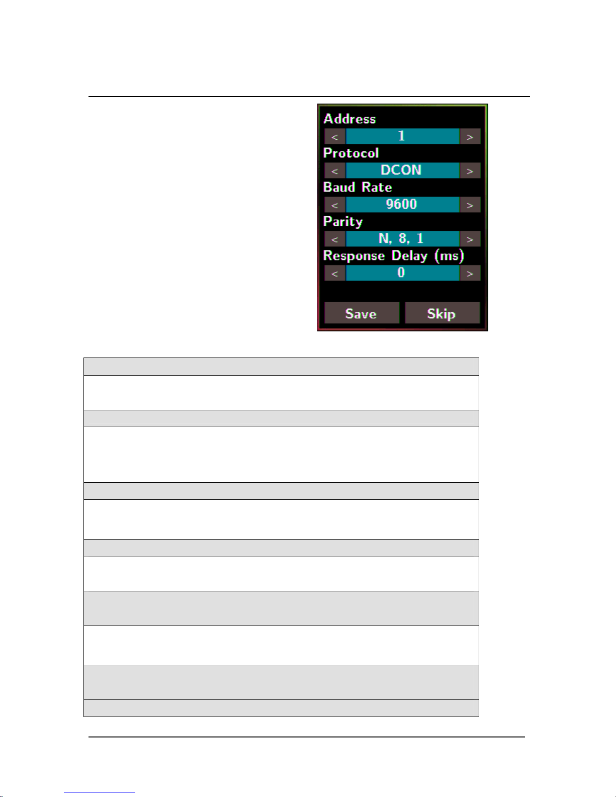
3.6 RS-485
Tap the RS-485 item in the Settings
menu to enter the sub-menu.
Address: Sets the address for a module.
Default: 1
Range: 0 ~ 255
Protocol: Sets the communication protocol.
- ModbusRTU (default)
- DCON
- DCONChkSum: uses DCON protocol and enables checksum
validation feature
Baud Rate
Default: 9600
Support Baud Rate: 1200/ 2400/ 4800/ 9600/ 19200/ 38400/ 57600/
115200 (unit: bps)
Parity
Default: N,8,1
Support format: N81, N82, E81, O81
Response Delay (ms): Sets the delay time between receiving the command
and sending the data.
Default: 0 ms
Range: 0 ~ 30 (unit: ms)
Save: Saves the modification and returns to the Settings menu.
All the changes take effect immediately after saving changes.
Skip: Returns to the Settings menu without saving any changes.
DL-300 Data Logger User Manual Version 1.1.0 Aug. 2015 - 26 -
4. Configuration via Web Browser
DL-300 logger has a built-in web server that provides simple web pages for
remote monitoring real-time data and configuring the logger with a standard
browser. For opening the web page in DL-300, the factory default IP address
(192.168.255.1), Subnet Mask (255.255.0.0) and Gateway (192.168.0.1) need
be set to available IP/Subnet Mask/Gateway addresses in your Ethernet
environment. The Ethernet configuration can be set by entering the Settings
menu from the touch screen or by web pages.
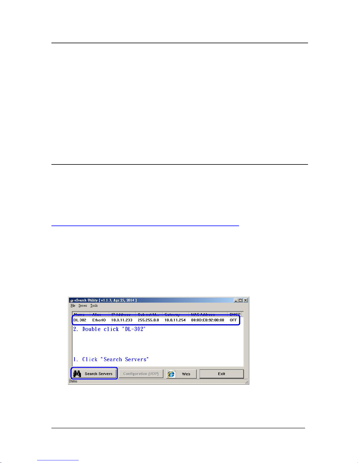
4.1 Search the DL-300 logger
eSearch is designed to search out the DL-300 logger connected on the same Ethernet
network, it supports for Linux and Windows and is needless to install.
The eSearch can be downloaded from
CD:\Napdos\dl-300\utility\esearch\
http://ftp.icpdas.com/pub/cd/usbcd/napdos/dl-300/utility/esearch/
Before running eSearch, turn off firewall on computer, and connect the computer and
DL-300 logger to Ethernet network.
1. Launch eSearch, click the Search Servers button to search the DL-300 modules
connected to the network, the modules searched out will be listed as below.
2. Double click the module name searched in the list.
 Loading...