

Page 1
Classification
UA-Series English Function Wizard FAQ-cnv-04
Author
Eva Li
Version
1.0.0
Date
2021, 04
Page
1 / 15
ICP DAS Co., Ltd. Technical Document
FAQ-CNV-04: UA Web UI Function Wizard – Module Communication Conversion -
How to Convert Modbus TCP / MQTT ? (Use DL-302)
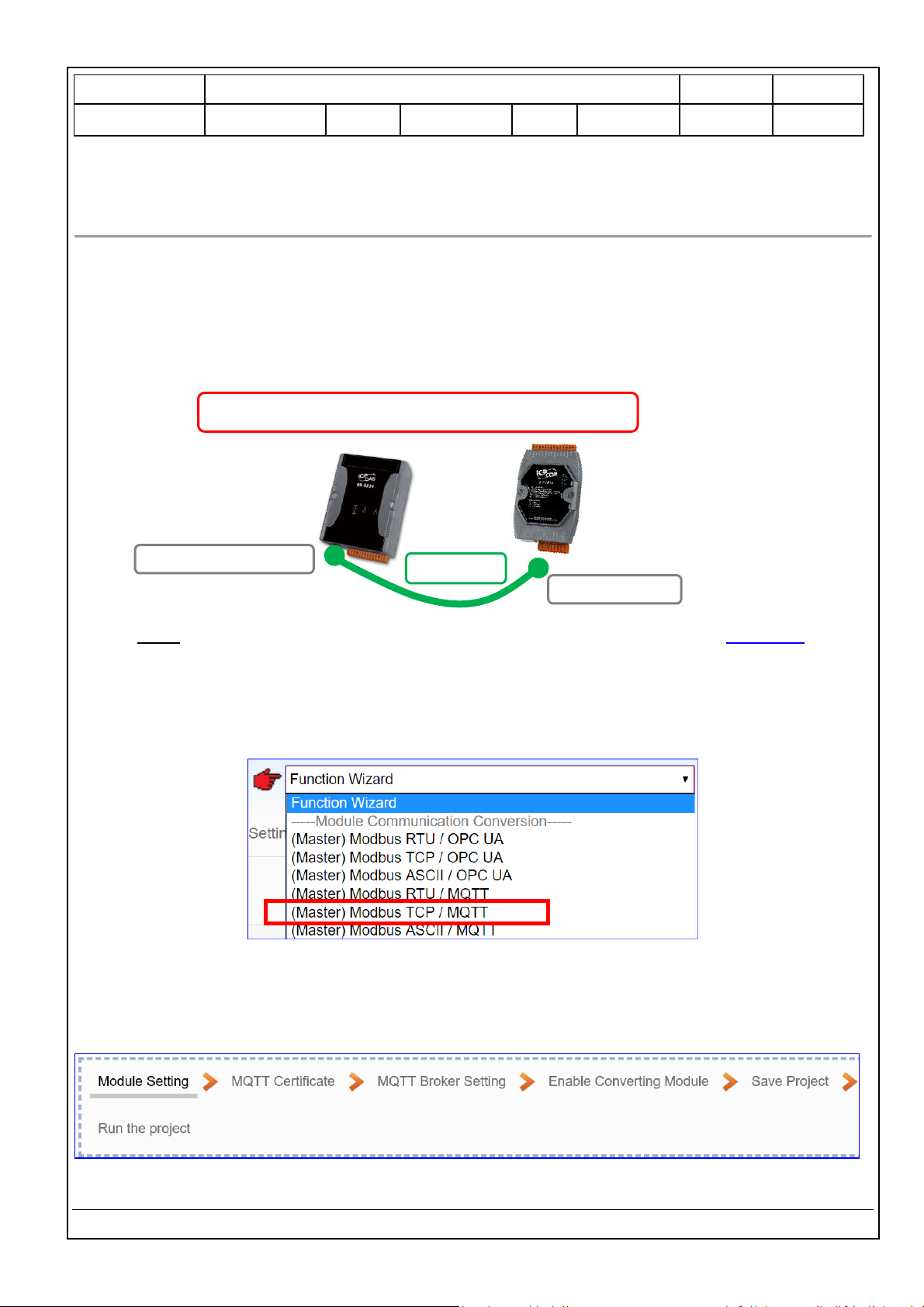
Modbus / MQTT Conversion include the conversion of MQTT and Modbus RTU / TCP / ASCII three
protocols. With the MQTT Service function, users can set the MQTT client to publish the message to the
specified broker or subscribe the topic, and so to read and write the single channel of the Modbus device
that connected to the controller.
Convert Setting: Modbus TCP and MQTT
Note: The hardware/network connection methods please see the UA Manual Chapter 2 .
When UA series controller connects the Modbus TCP (via Ethernet, as the picture) and read/write the
Modbus I/O via MQTT Broker, user can choose the item [Modbus TCP / MQTT] of the “Module
Communication Conversion” in the Function Wizard.
[Step Box]:
The Step Box of the [Modbus TCP / MQTT] has the steps as below. When enabling the Step Box, it autoenters the first step setting page (The step with a bold underline means it is the current step.). The user
just needs to follow the “Step Box” step-by-step and then can complete the project quickly and rightly.
Ethernet Port
Modbus
TCP
Modbus
Convert Setting: Modbus TCP and MQTT
Ethernet
LAN: Ethernet Port
UA Series
Controller
Page 2
Classification
UA-Series English Function Wizard FAQ-cnv-04
Author
Eva Li
Version
1.0.0
Date
2021, 04
Page
2 / 15
ICP DAS Co., Ltd. Technical Document
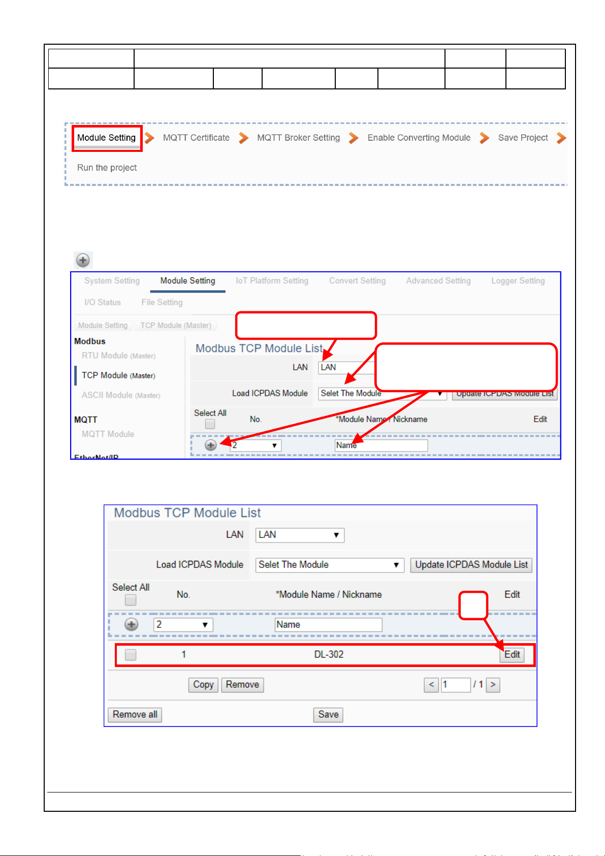
Step 1. Module Setting
This page is for setting the communication values of the connected modules.
The Ethernet port is LAN for connecting with the TCP module. If using ICP DAS module, select the
module and system will auto load the module data. If not, give a module name (Default: Name), click
[ ] button to add a new module.
Add a module (e.g. No.: 1, Name: DL-302) as below, and then click [Edit] button to enter the
“Module Content Setting” page.
If set up a wrong module, user can click the box in the left side of the module number and click the
[Remove] button to delete the module.
3
2. Select an ICP DAS module
or give a name, click “+” to add a
module.
1. Ethernet port: LAN
Page 3
Classification
UA-Series English Function Wizard FAQ-cnv-04
Author
Eva Li
Version
1.0.0
Date
2021, 04
Page
3 / 15
ICP DAS Co., Ltd. Technical Document
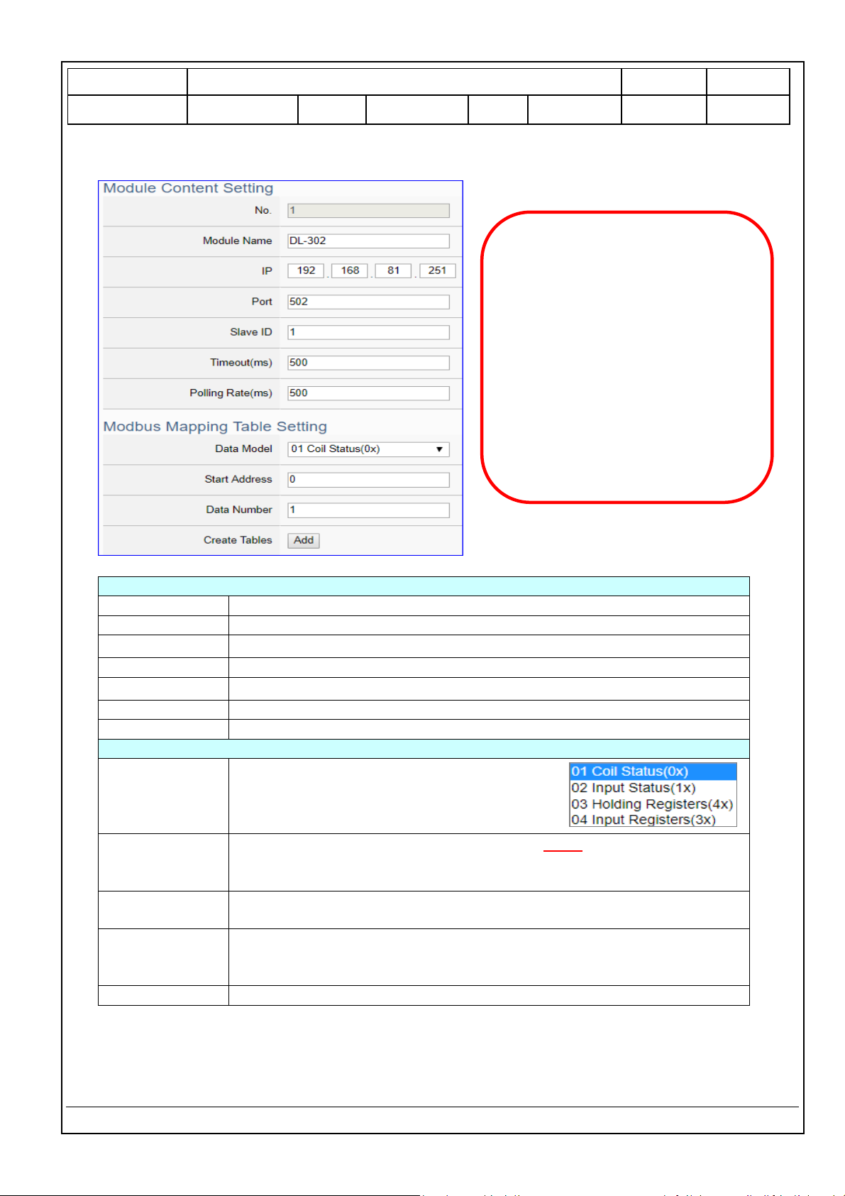
[Module Content Setting] page to set up IP and the Modbus address mapping table.
Module Content Setting
No.
The module number in the module list (Not editable here)
Module Name
Give a name, e.g. model number or name. Default: Name.
IP
Give the IP address of the connected module. Default: 0.0.0.0
Port
The port number for Modbus TCP. Default: 502
Slave ID
Set the Slave ID of the UA. (Range: 1 ~ 247)
Timeout
Set the timeout value for the module. Default: 500 ms
Polling Rate
Set a time interval for the command. Default: 500 ms
Modbus Mapping Table Setting
Data Model
System provides 4 Modbus data models “01”
~ “04” for mapping to address of
DO, DI, AO and AI. (ex. 01: DO
channels, 02: DI, 03: AO, 04: AI)
Start Address
The start address of the Modbus command. Note: the Start Address of
UA is bass on 0, even if some modules are bass on 1, here it needs to
follow UA to set bass on 0.
Data Number
The number of the Modbus address. Need to give enough number for
the DO, DI, AO, AI channels of the module. Default: 1.
Type
This item only when the data model is 03 or 04. Choose the suitable data
type: 16-bit Short, 16-bit Unsigned Short, 32-bit Long, 32-bit Unsigned
Long, 32-bit Float, 64-bit Double.
Create Tables
Click [Add] button, it will add a table in the Modbus mapping table.
The finished Modbus Mapping Table as below is in order of DO, DI, AO and AI.
This Example: DL-302
[IP] 192.168.81.251 (by user case)
[Modbus Mapping Table Setting]
Data Model: 04 Input Registers(3x)
Start Address: 0
Data Number: 6
Type: 16-bit Short
Click [Add]
Page 4
Classification
UA-Series English Function Wizard FAQ-cnv-04
Author
Eva Li
Version
1.0.0
Date
2021, 04
Page
4 / 15
ICP DAS Co., Ltd. Technical Document
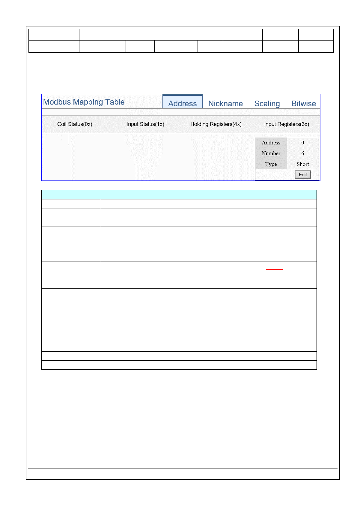
Address:
Display and edit the Modbus Mapping Table.
Modbus Mapping Table – Address Setting
Address Setting
The “Address Setting” page of the Modbus Mapping Table
Nickname Setting
Click can switch to the The “Nickname Setting” page of the Modbus
Mapping Table. (Next page)
Modbus Mapping
Table
Coil Status(0x): Mapping to DO Modbus address
Input Status(1x): Mapping to DI Modbus address
Holding Registers(4x): Mapping to AO Modbus address
Input Registers(3x): Mapping to AI Modbus address
Address
The start address of the Modbus command. Default: 0. Note: the Start
Address of UA is bass on 0, even if some modules are bass on 1, here it
needs to follow UA to set bass on 0.
Number
The number of the Modbus address. Need to give enough number for
the DO, DI, AO, AI channels of the module. At least 1.
Type
DO/DI type: Bool (Boolean)
AO/AI type: depend on setting of [Modbus Mapping Table Setting]
Edit
Click to change the address and Number.
Delete
Click to delete this address table.
Save
Click to save and exit this table editing.
Cancel
Click to exit without saving and back to the module list page.
OK
Click to save this page settings and back to the module list page.
Page 5
Classification
UA-Series English Function Wizard FAQ-cnv-04
Author
Eva Li
Version
1.0.0
Date
2021, 04
Page
5 / 15
ICP DAS Co., Ltd. Technical Document
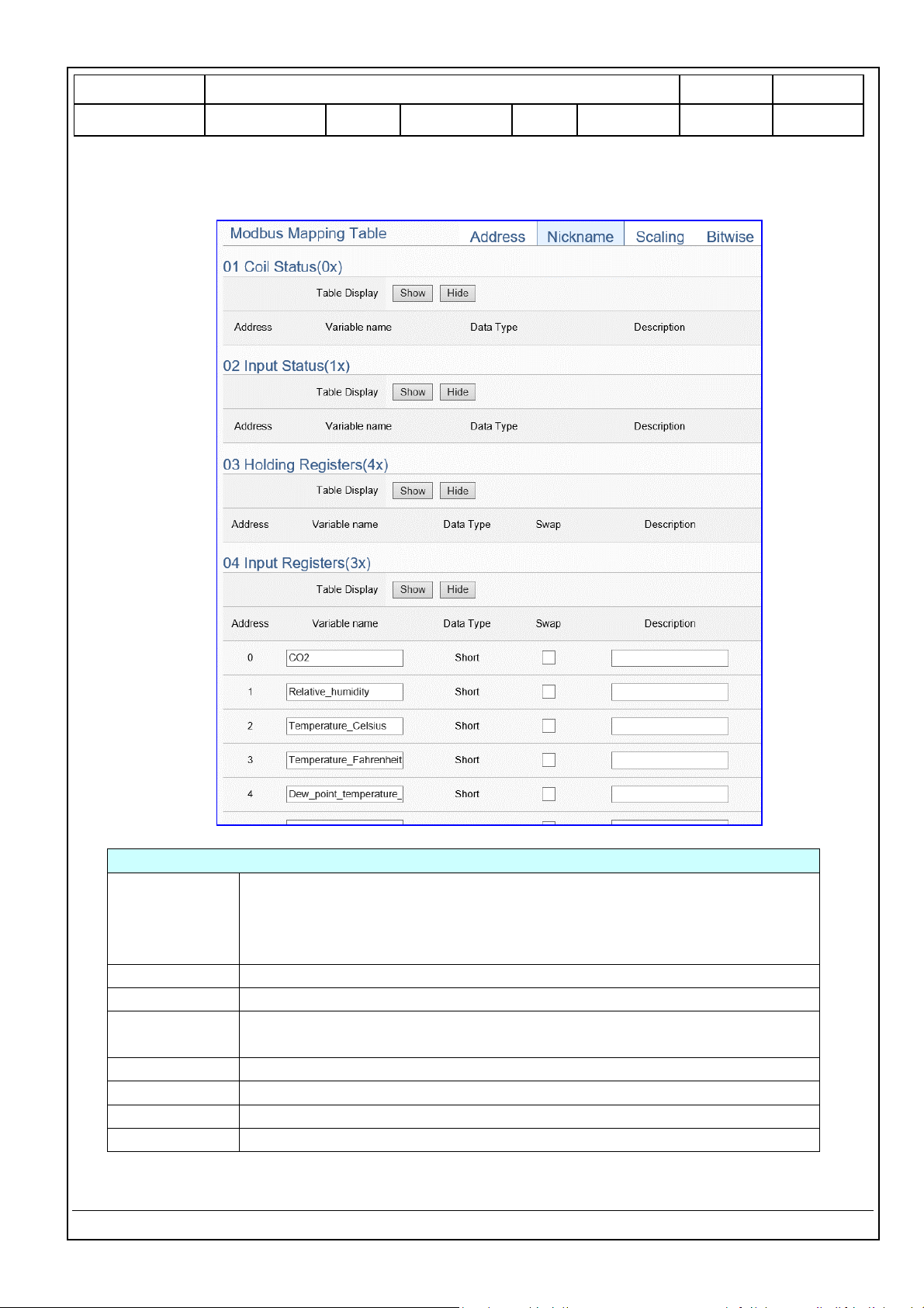
Nickname:
Setting the variable nickname and description.
Modbus Mapping Table – Nickname Setting
Modbus
Mapping Table
Coil Status(0x): Mapping to DO Modbus address
Input Status(1x): Mapping to DI Modbus address
Holding Registers(4x): Mapping to AO Modbus address
Input Registers(3x): Mapping to AI Modbus address
Table Display
Click [Show] to display all fields, click [Hide] to hide some fields.
Address
Modbus address. System auto arrange.
Variable name
The variable name of the mapping address. Default: Tag0 and auto
arrange the number. User can define the name.
Data Type
Display data type of the variable. (Not editable)
Swap
Check to swap the byte order (Lo-Hi/Hi-Lo) for 4-byte or 8-byte.
Description
Write a note for this variable.
OK
Click to save this page settings and back to the module list page.
Page 6

Classification
UA-Series English Function Wizard FAQ-cnv-04
Author
Eva Li
Version
1.0.0
Date
2021, 04
Page
6 / 15
ICP DAS Co., Ltd. Technical Document
Scaling:
Scaling is only available in the AI/AO settings of Modbus RTU/TCP. When the variable value needs to be
scaled or converted before output, click the "Advanced Setting" button of the variable on the Scaling
page, input the Min./Max./Offset of the Reference/Output items, add a description, and check "Enable"
box, The Scaling conversion function will be activated.
Modbus Mapping Table – Scaling
Modbus
Mapping Table
Holding Registers(4x): Mapping to AO Modbus address
Input Registers(3x): Mapping to AI Modbus address
Scaling do not support 01 Coil Status(0x):DO & 02 Input Status(1x):DI
Table Display
Click [Show] to display all fields, click [Hide] to hide some fields.
Address
Modbus address. System auto arrange.
Reference
The I/O variable of the Modbus address.
Output
The scaling variable for scaling output. User can define the variable name.
Scaling
Click [Show Detail] to set up the Scaling parameters, and click [Hide Detail] to hide
the parameters.
Fill in the Min/Max range values of the source in the Reference column. Fill in the
Min/Max range values after scaling in the Output column. If needs offset, fill the
offset value in the Offset item. Remember check “Enable” box.
Enable
Check the box of the variable can enable just that variable for scaling.
Description
Write a note for this variable.
OK
Click to save this page settings and back to the module list page.
Page 7

Classification
UA-Series English Function Wizard FAQ-cnv-04
Author
Eva Li
Version
1.0.0
Date
2021, 04
Page
7 / 15
ICP DAS Co., Ltd. Technical Document
Bitwise:
Bitwise is only available in the AI/AO settings of Modbus RTU/TCP. When the data needed to take out
the value of the specified bit, fill in the variable name in the specified Bit# of the required address, and
the value of the bit can be output to the filled variable.
The M-7055D has no AI/AO, so here uses other module’s setting screen as an example.
Modbus Mapping Table – Bitwise
Modbus
Mapping Table
Holding Registers(4x): Mapping to AO Modbus address
Input Registers(3x): Mapping to AI Modbus address
Bitwise do not support 01 Coil Status(0x):DO & 02 Input Status(1x):DI
Bitwise do not supports 32-bit Float & 64-bit Double data types.
Table Display
Click [Show] to display all fields, click [Hide] to hide some fields.
Address
Modbus address. System auto arrange.
Reference
The Bit# variables of the Modbus address.
Bitwise
Set up the variables for Bitwise. Click [Advanced Settings] to set up the Bitwise
parameters, and click [Hide] to hide the parameters.
Fill in the variable names to the Bit# that wanted to do the Bitwise. The value in
the fixed bit number will be assigned into the variable.
OK
Click to save this page settings and back to the module list page.
Page 8

Classification
UA-Series English Function Wizard FAQ-cnv-04
Author
Eva Li
Version
1.0.0
Date
2021, 04
Page
8 / 15
ICP DAS Co., Ltd. Technical Document
Step 2. MQTT Certificate
The [MQTT Certificate] is for setting up security communications to upload the MQTT Trusted Certificate,
Certificate and Private Key. The users upload the file to the UA controller according to the type of
obtained certificate. If you want to perform Broker authentication, you need to upload the Trusted
Certificate. If you want to perform the Broker/Client two-way authentication, you need to upload the
Credential and Private Key additionally. The user can skip this step if the user project does not use
certificate transmission security.
File Setting > MQTT Certificate > Upload the file to the controller
Trusted
Certificate
Select File: select the MQTT Trusted Certificate file of the device.
Upload: upload the MQTT Trusted Certificate file to the UA controller.
File format must be PEM. Extension name must be “pem / cer / crt”.
If select a wrong file, the system will show an error message.
Certificate
Select File: select the MQTT Certificate file of the device.
Upload: upload the MQTT Certificate file to the UA controller.
File format must be PEM. Extension name must be “pem / cer / crt”.
If select a wrong file, the system will show an error message.
Private Key
Select File: select the MQTT Private Key of the device.
Upload: upload the MQTT Private Key file to the UA controller.
File format must be PEM. Extension name must be “.key”.
If select a wrong file, the system will show an error message.
Page 9

Classification
UA-Series English Function Wizard FAQ-cnv-04
Author
Eva Li
Version
1.0.0
Date
2021, 04
Page
9 / 15
ICP DAS Co., Ltd. Technical Document
Step 3. MQTT Broker Setting
Click the next step, and enter the Step 3 [MQTT Broker Setting] of the UI setting.
This page is for setting the IoT platform and the MQTT Broker connection, e.g. the local or remote
broker, port, login information, etc.
We select the “Modbus RTU / MQTT” conversion at the beginning, so this step will auto enter the
[MQTT Connection > Local Broker] page of IoT Platform Setting. The “Step Box” will prevent the user
from selecting the wrong platform. User can choose the local or remote broker for the MQTT
connection.
The example uses local Broker.
Local Broker
MQTT Connection > Local Broker Setting
Port
The COM port of the Local MQTT Broker. System default: 1883
Anonymous Login
Check to allow anonymous login. Default: Check.
Save
Click to save the setting of this page.
Page 10

Classification
UA-Series English Function Wizard FAQ-cnv-04
Author
Eva Li
Version
1.0.0
Date
2021, 04
Page
10 / 15
ICP DAS Co., Ltd. Technical Document
If users apply a remote Broker, the screen will as follow.
Remote Broker:
MQTT Connection > Remote Broker List
Broker Name
The name of the remote MQTT Broker.
User can define the name, e.g. Broker1. Default: Name.
Click to add a new remote Broker.
Save
Click to save the settings of this page.
After creating a new Remote Broker (as below):
MQTT Connection > Remote Broker List
Broker Name
The name of the remote MQTT Broker.
User can define the name, e.g. Broker1. Default: Name.
IP / Domain
The IP address of the remote Broker. Default: 127.0.0.1
Port
The COM port of the remote Broker. Default: 1883
Edit / Remove
Click [Edit] can set the Broker.
Click the left box and [remove] can delete the Broker.
Save
Click to save the settings of this item.
Page 11

Classification
UA-Series English Function Wizard FAQ-cnv-04
Author
Eva Li
Version
1.0.0
Date
2021, 04
Page
11 / 15
ICP DAS Co., Ltd. Technical Document
MQTT Connection > Remote Broker > Broker Content Settings
Broker Name
The name of the remote MQTT Broker. (Editable)
IP / Domain
The IP address of the remote Broker. Default: 127.0.0.1
Port
The COM port of the remote Broker. Default: 1883
Keep Alive Time
The keep alive time. Default: 60 (second)
SSL/TLS
Check to enable the supporting of SSL/TLS security communication.
Default: uncheck.
Anonymous Login
Check to allow anonymous login. Default: Check.
OK
Click to save the settings and exit.
Page 12

Classification
UA-Series English Function Wizard FAQ-cnv-04
Author
Eva Li
Version
1.0.0
Date
2021, 04
Page
12 / 15
ICP DAS Co., Ltd. Technical Document
Step 4. Enable Converting Module
Click the next step, and enter the Step 3 [Enable Converting Module] UI setting
This step is for enabling the module for the Modbus TCP / MQTT conversion.
We select the “Modbus TCP / MQTT” conversion at the beginning, so this step will auto enter the
[MQTT > Modbus TCP (Master)] page of Conversion setting. The “Step Box” will prevent the user
from selecting the wrong platform.
Convert Setting > MQTT > Modbus TCP (Master) Module List
No.
The module number in the module list (Not editable here)
*Module Name
/ Nickname
The module name set in the module list (Not editable here)
All Enabled
Check [All Enabled] box to enable all modules in list for conversion.
Default: Uncheck.
Check the box of each module can enable just that module for
conversion.
Edit
Click to enter the “MQTT Client Setting” page to set up the Topic, QoS,
Publish, Subscribe …
The page number of the module list: Current page / Total pages. Click <
or > to go to the previous or next page.
Save
Click to save the settings of this page.
Page 13

Classification
UA-Series English Function Wizard FAQ-cnv-04
Author
Eva Li
Version
1.0.0
Date
2021, 04
Page
13 / 15
ICP DAS Co., Ltd. Technical Document
Click [Edit] button cauld enter the “MQTT Client Setting” page:
Convert Setting > MQTT > Modbus TCP (Master) – MQTT Client Setting
No.
The module number in the module list (Not editable here)
Module Name
The module name set in the module list (Not editable here)
Scan Rate(ms)
Set an update frequency for the task data. Default: 1000 (Unit: ms)
Dead Bend
Give a dead bend value for updating a float signal. Default: 0
Will Topic
Enter the title of a disconnect notice. Default: Null.
Will
Enter a disconnect notice. Default: Null.
MQTT
Connection
Check the Broker want to use Local Broker or Remote Broker.
Page 14

Classification
UA-Series English Function Wizard FAQ-cnv-04
Author
Eva Li
Version
1.0.0
Date
2021, 04
Page
14 / 15
ICP DAS Co., Ltd. Technical Document
Convert Setting > MQTT > Modbus TCP (Master) – Publish & Subscribe
Details
Click [Show] to display all fields, click [Hide] to hide some fields.
Name
The variable name of the mapping address. (Not editable here)
Attribute
Display data attribute of the variable. (Not editable)
Include: Read, Read/Write…
Data Type
Display data type of the variable that set in the Modbus Address
Mapping Table page. (Not editable) Include: Bool, Short, Float…
Subscribe Topic
The topic of receiving/subscribing data message.
Subscribe Qos
The subscribe Qos (Quality of Service) levels. Default: 2
0: Delivering a message at most once.
1: Delivering a message at least once.
2: Delivering a message at exactly once.
Publish Topic
The topic of sending/publishing data message.
Publish Qos
The publish Qos (Quality of Service) levels. Default: 2
0: Delivering a message at most once.
1: Delivering a message at least once.
2: Delivering a message at exactly once.
Retain
Check [Retain] box of the top row can store the broker message for all
variables in list. Check the box of each variable can store the broker
message just that variable. Default: Uncheck.
Enabled
Check [Enabled] box of the top row can enable all variables in list.
Check the box of each variable can enable just that variable for
conversion. Default: Uncheck.
OK
Click to save this page settings and back to the module list page.
Page 15

Classification
UA-Series English Function Wizard FAQ-cnv-04
Author
Eva Li
Version
1.0.0
Date
2021, 04
Page
15 / 15
ICP DAS Co., Ltd. Technical Document
Step 5. Save Project
The setting of this example is finished now. Click the next step [Save Project], the Step Box will show
an animation as below picture, that means the project is saving. When the animation vanished, the
project is saved completely.
Step 6. Run the Project
The project, after saving, needs to be executed. Click the next step [Run the Project]. This step can
also via the [System Setting > Controller Service Setting > Run Project] to Stop and Run the project.
When the words “Please wait” disappears, the new words “Success” appears, that means the UA
controller is running new project successfully. Then the Step Box will disappear automatically now,
and back to the first screen view of the Web UI.
The new project now completes the setting, uploading and running in the UA controller and can
process the conversion communication. Users can see the I/O status from the menu [I/O Status]. For
more about the Web UI settings, please refer to CH4 and CH5.
 Loading...