

CAN-8124/CAN-8224/CAN-8424 Quick Start User Guide (Version .2.0, Aug/2007) ------ 1
CA
N
-
8124/CA
N
-
8224/CA
N
-
8424
Quick Start User Guide
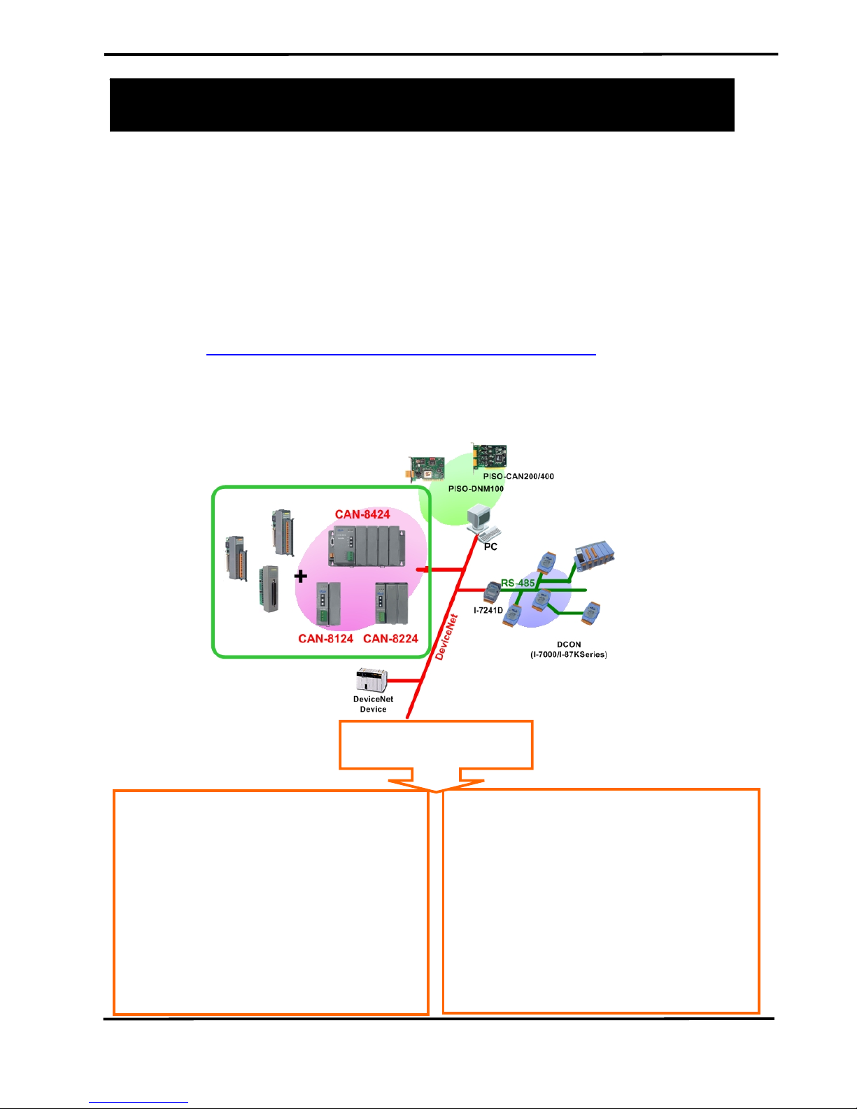
1. Introduction
This manual introduces the user to the methods used to implement
the CAN-8x24 devices into their applications in a quick and easy way.
This will provide users with only basic instructions. For more detailed
information, please refer to the user manual located on the ICPDAS CDROM or download it from the ICPDAS web site:
http://www.icpdas.com/download/download-list.htm
The goal for this manual is focused on helping users to quickly
familiarize themselves with the CAN-8x24 devices. Users can apply the
CAN-8x24 devices as follows.
● Complies with DeviceNet specification
Volume I, Release 2.0& Volume II,
Release 2.0
● Group 2 Only Slave; (non UCMMcapable)
● Supports Predefined Master/slave
Connection Set
● Supports Fragmented Explicit Message
● Dynamic Assembly Objects Mapping
● I/O operating modes: Polling, Bit-
Strobe, Change of State/Cyclic
● Supports Device Heartbeat message
● Supports Device Shutdown message
● EDS file dynamically
● Data rate and Node Address (MAC ID)
configured via rotary switch
Features
CAN-8124/CAN-8224/CAN-8424 Quick Start User Guide (Version .2.0, Aug/2007) ------ 2
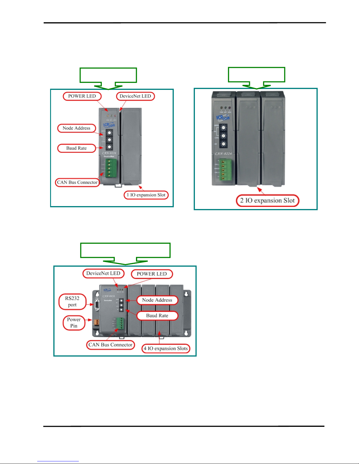
2.Hardware structure
z 8KDNSx Hardware Structure
z 8x20 Hardware Structure
CAN-8224
CAN-8124
-
CAN-8124/CAN-8224/CAN-8424 Quick Start User Guide (Version .2.0, Aug/2007) ------ 3
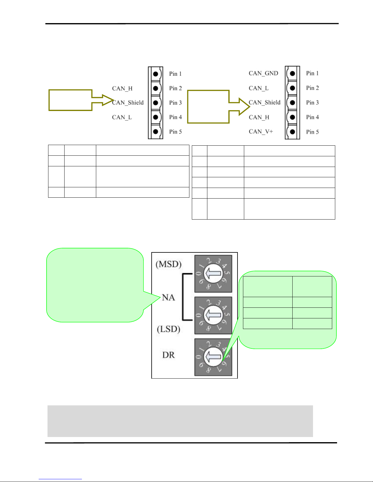
z Pin assignment
CAN-8424
CAN-8124
CAN-8224
z Rotary Switch
Note: If users set the illegal values of the rotary switch, the MOD led will flash when
the system is powered up. If this condition occurs, users must configure the
legal values of the switches and reset the device, and then the device should
work normally.
Pin. Signal Description
2 CAN_H CAN_H bus line (dominant high)
3
CAN_SH
LD
Optional CAN Shield
4 CAN_L CAN_L bus line (dominant low)
Pin Signal Description
1 CAN_GND Ground (0V)
2 CAN_L CAN_L bus line (dominant low)
3 CAN_SHLD Optional CAN Shield
4 CAN_H CAN_H bus line (dominant high)
CAN external positive
supply (I-8KCPSx power)
5 CAN_V+
MSD: the most significant
digit of the node address.
Rotary Switch
Value
Baud rate
(K BPS)
0 125
1 250
2 500
LSD: the low significant
digit of the node address

CAN-8124/CAN-8224/CAN-8424 Quick Start User Guide (Version .2.0, Aug/2007) ------ 4
z Terminal Resistance
z LED Description
PWR LED
condition status indicates
Off No power No power supply
Solid red Normal Device is working
MOD LED
condition status indicates
Off Normal Normal
Solid Critical fault Device has unrecoverable fault;
Flashing Non_critical fault
Device has recoverable fault; to recover:
Reconfigure device
Reset device
Perform error recovery
NET LED
condition status indicates
Off Off line DeviceNet is not online
Flashing On line DeviceNet is on line, but not communicating
Init solid Link failed
(Critical) Device has detected an error that
has rendered it incapable of communicating
on the link; for example, detected a
duplicate node address or network
configuration error
Solid On line, communicating DeviceNet is on communication

CAN-8124/CAN-8224/CAN-8424 Quick Start User Guide (Version .2.0, Aug/2007) ------ 5
3. How to Start
Select the necessary ICP DAS I-8K/I87K IO modules of ICP DAS in your
DeviceNet application.
CAN-8124/CAN-8224 just only
supports off-line mode.
After configuring the CAN-8x24 and
creating the specific EDS files, apply
the EDS file to your DeviceNet
application.
3. Produce the corresponding EDS file.
2. Select the proper module slot No. and
name for each I-8000/I-87K module
plugged in the CAN-8x24
1. Execute CAN Slave Utility in the on-
line/off-line mode

CAN-8124/CAN-8224/CAN-8424 Quick Start User Guide (Version .2.0, Aug/2007) ------ 6
4. Installation & Configuration
Before users first use the CAN-8x24, the CAN Gateway Utility can help to
configure and create EDS files.
Step 1: Please install the CAN Slave Utility. You can find the software from our web
site: http://www.icpdas.com/download/download-list.htm or the follow path of
“/CAN-CD/DeviceNet/Slave/CAN-8x24/Utility/ on the CD provided.
Step 2: There are 2 modes in the CAN Slave Utility. One mode is off-line and it allows
users to create EDS files off-line for the CAN-8x24. Another mode is on-line mode.
Before using the CAN Slave utility in the On-line mode with the CAN-8424, please
make sure that you have connected the COM1 port to the CAN-8424 with the available
COM port on your PC.
Note: In the on-line mode, users can define the needed assembly instance or
default assembly instance, and set the IO connection path. But in off-line mode,
we provide the default assembly instance for the CAN-8124/CAN-8224. The IO
connection path must be set via an explicit connection.
Off-line mode
On-line mode
For CAN-8124/CAN-8224
Only for CAN-8424

CAN-8124/CAN-8224/CAN-8424 Quick Start User Guide (Version .2.0, Aug/2007) ------ 7
5.The relationship between the application and assembly
objects
The components of the Assembly Objects
Example: In the demo, apply the I-87017 (slot 0), I-8024 (slot 1), I-8053 (slot 2) and I-
8057 (slot 3) into the CAN-8424.
Parts of the attributes in the Application instance
Slot
Address
Application
Instance ID
Module
name
DO
Length(Byte)
AO
Length(Byte)
DI
Length(Byte)
AI
Length(Byte)
0 0x01 87017 0 0 0 16
1 0x02 8024 0 8 0 0
2 0x03 8057 2 0 0 0
3 0x04 8053 0 0 2 0
The components of assembly objects
Assembly Object Instance
ID(Hex)
Data Length(Byte) Component modules
0x64 DO: 2 I-8053 (ch0~ch15)
0x65 AO: 8 I-8024 (ch0~ch3)
0x66 DI: 2 I-8057 (ch0~ch15)
0x67 AI: 8 I-87017 (ch0~ch3)
0x68 AI: 8 I-87017 (ch4~ch7)

CAN-8124/CAN-8224/CAN-8424 Quick Start User Guide (Version .2.0, Aug/2007) ------ 8
Application instance attributes
Attribute ID Description Method Data Type
Default
Value
0x01 Module name Get WORD 0
0x02 Module Type Get CHAR 0
0x03 Configuration Get Depend on the
number of channels
0
0x04 Total Channels Get CHAR 0
0x05 Total Length Get CHAR 0
0x06 Reserved Get CHAR 0
0x07 DO Length Get CHAR 0
0x08 AO Length Get CHAR 0
0x09 DI Length Get CHAR 0
0x0A AI Length Get CHAR 0
0x0B DO channel num Get CHAR 0
0x0C AO channel num Get CHAR 0
0x0D DI channel num Get CHAR 0
0x0E AI channel num Get CHAR 0
0x14 DO data Set Defined by module
channel num
0
0x15 AO data Set Defined by module
channel num
0
0x16 DI data Get Defined by module
channel num
0
0x17 AI data Get Defined by module
channel num
0
6.Steps toward implementing DeviceNet applications using
the command set:
1. Request the use of the Predefined Master/Slave Connection Set.
2. Set the Master’s Explicit Request Messages to set the expected_packet _rate
attribute for the IO connection to establish an I/O Connection Object State.
3. There are two ways to access IO modules. The first method is by way of the IO
connection object. The other is by using an explicit message to set/get the IO
attribute for the application object.
4. Release the use of the Predefined Master/Slave Connection Set.
 Loading...