

Page 1

ALM-06-WF User’s Manual
www.icpdas.com
Warranty
All products manufactured by ICP DAS are under warranty regarding
defective materials for a period of one year from the date of delivery to the
original purchaser.
Warning
ICP DAS assumes no liability for damages resulting from the use of this
product. ICP DAS reserves the right to change this manual at any time without
notice. The information furnished by ICP DAS is believed to be accurate and
reliable. However, no responsibility is assumed by ICP DAS for its use, or for any
infringements of patents or other rights of third parties resulting from its use.
Copyright
Copyright 2019 by ICP DAS. All rights are reserved.
Trademark
The names used for identification only may be registered trademarks of their
respective companies.
ALM-06-WF User’s Manual (Rev1.0, Feb./2019) ------------- 1
Page 2

ALM-06-WF User’s Manual
Document Revision
Version Date Description of changes
Rev1.0 2019-05-17 First release for ALM-06-WF
ALM-06-WF User’s Manual (Rev1.0, Feb./2019) ------------- 2
Page 3

ALM-06-WF User’s Manual
Table of Contents
1. Introduction .......................................................................................... 5
1.1 Wireless connection mode ................................................................... 5
1.2 Features .............................................................................................. 5
1.2.1 Features Description ........................................................................ 6
1.3 Specifications ...................................................................................... 7
2. Hardware.............................................................................................. 9
2.1 Outward Appearance .......................................................................... 9
2.1.1 LED Indicator ................................................................................. 10
2.1.2 Connector Pin Define ..................................................................... 10
2.2 Reset to default .................................................................................. 11
2.3 Dimensions ........................................................................................ 11
2.4 Wire Connection ............................................................................... 12
2.4.1 Wire connection define ................................................................... 12
2.4.2 I/O connection ................................................................................ 12
3. Software.............................................................................................. 14
3.1 ALM Utility(AP Mode) ..................................................................... 14
3.1.1 Main Screen ................................................................................... 14
3.1.2 Controller Status ............................................................................... 15
3.1.3 DI/DO Status & Control .................................................................... 15
3.1.4 Status Bar ........................................................................................ 15
3.1.5 Icon Button ...................................................................................... 16
3.1.6 Configuration/Setup ....................................................................... 17
3.2 Station Mode (STA) IP scanner ......................................................... 19
3.3 Alarm Mode & Audio Editor ............................................................. 20
3.4 Start your Edit .................................................................................. 21
3.4.1 Make a Micro SD from project ........................................................... 24
3.4.2 Insert a New MicroSD ....................................................................... 24
3.5 Alarm Mode Description ................................................................... 25
4. Application ......................................................................................... 29
4.1 Connection with Modbus TCP utility................................................. 29
5. Modbus Applications ........................................................................... 31
5.1 What is Modbus TCP/IP? ................................................................. 31
5.2 Protocol Description ......................................................................... 32
5.2.1 MBAP ............................................................................................. 32
5.2.2 Function Code .................................................................................. 33
5.2.3 Data ................................................................................................ 33
5.2.4 Response ......................................................................................... 34
ALM-06-WF User’s Manual (Rev1.0, Feb./2019) ------------- 3
Page 4

ALM-06-WF User’s Manual
5.2.5 Data Encoding .................................................................................. 34
5.3 ALM-06-WF Address Mapping ......................................................... 35
ALM-06-WF User’s Manual (Rev1.0, Feb./2019) ------------- 4
Page 5
ALM-06-WF User’s Manual
1. Introduction
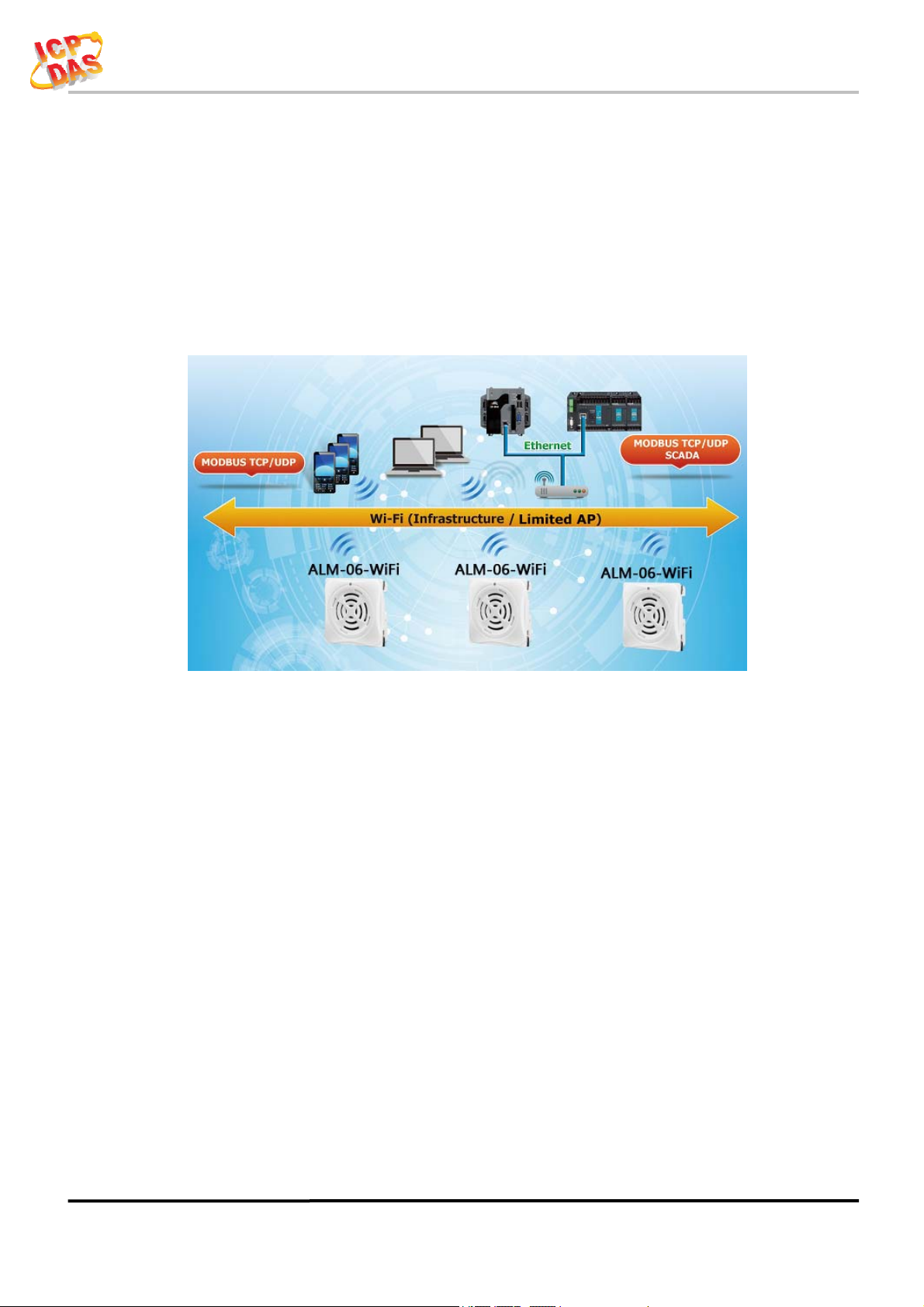
The ALM-06-WF have WLAN connection complies with the IEEE802.11b/g/n
standards. With the popularity of 802.11 network infrastructure, the ALM-06-WF make
an easy way to incorporate wireless connectivity into monitoring and configuration.
They also support Modbus TCP protocol and the network encryption configuration,
which makes perfect integration to SCADA software and offer easy and safe access for
users from anytime and anywhere.
Figure 1-1: Application architecture for the ALM-06-WF
1.1 Wireless connection mode
ALM-06-WF support both Access Point(AP) & Station(STA) wireless
connection modes of WLAN.
1.2 Features
Wi-Fi communication monitoring and configuration
Compatible with IEEE 802.11b/g/n standards
Support Access Point(AP, 1 Client) & Station(STA) modes for wireless networks
Support WEP, WPA and WPA2 wireless encryption
Support Modbus TCP monitoring
Support DHCP Server(AP), DHCP Client or Static IP(STA) network configuration
Wide operating temperature range
Wide power supply range
Photo couple input, Relay output
MP3 Audio Output, external Line out
Digital Volume control
8 Alarm mode support
ALM-06-WF User’s Manual (Rev1.0, Feb./2019) ------------- 5
Page 6

ALM-06-WF User’s Manual
1.2.1 Features Description
The ALM-06-WF offers the most comprehensive configuration to meet specific
application requirements. The following list shows the features designed to simplify
installation, configuration and application.
Compatible with IEEE 802.11b/g/n standards
ALM-06-WF complied with IEEE 802.11b/g/n standard from 2.4~2.5 GHz, and it
can be used to connect your wireless LAN.
Support Access Point(AP) & Station(STA) modes for wireless networks
AP mode lets you create a Limited AP(1 Client access allow) network with the
specified SSID to communicate directly with each other without the need for a wireless
access point.
STA mode is the more common network configuration where all wireless clients
connect to the wireless network via a WAP (Wireless Access Point).
Support WEP, WPA and WPA2 wireless encryption
WEP and WPA are common types of security that are used to protect wireless
networks. When WEP or WPA is turned on, ALM-06-WF uses a special security key
combination to allow only devices that know this key to connect to its wireless network.
This applies to laptops, smart device, or any other wireless device.
Support Modbus TCP protocols
The Modbus TCP server function on the ALM-06-WF can be used to provide data
monitoring from HMI/SCADA software built with Modbus TCP driver.
Also there is some other HMI Modbus App in Android Google Play you can use.
Built-in MP3 Audio decoder & Output
The Alarm sound output using MP3(MPEG1-Audio Layer Ⅲ) audio, it support most
of MP3 format(Sample Rate 24/44.1(prefer)/48 KHz, Bit Rate 32 64 96 128(prefer) 160
192 Kbit/s), include an 3W audio power amplifier & 1KΩ Impedance Line Out can send
the alarm sound to external PA(Power Amplifier) system.
Support 6 channel trigger input with 8 alarm mode
Include 6 channel Photo couple input & 8 kinds of mode for trigger alarm, it also
can be trigger an extend device using external Relay Output. All modes & MP3 audio
files can be monitoring, configuration & download from PC Utility, it also can monitor
status form Android APP.
ALM-06-WF User’s Manual (Rev1.0, Feb./2019) ------------- 6
Page 7

ALM-06-WF User’s Manual
r
r
1.3 Specifications
Table 1-1: System Specifications
Wi-Fi Interface
Antenna Chip Antenna
Output Power 18.0 dBm @ 1 DSSS/14.5 dBm @ 54 OFDM
Receive Sensitivity –95.7 dBm @ 1 DSSS/–74.0 dBm @ 54 OFDM
Interface Wi-Fi 2.4G
Standard Supported IEEE 802.11b/g/n
Wireless Mode Station & AP (1 Client)
Encryption WEP, WPA and WPA2
Service TCP, Modbus TCP
LED Indicators
One 2 colors LED, Blue for System status,
Power/Status
Purple(Blue+Red)for Connective status/Locato
Isolation
Intra-module Isolation,
Field-to-Logic
Protection
ESD (IEC 61000-4-2) ±8 kV Air for Random Point
EFT (IEC 61000-4-4) ±2 kV for Powe
Waterproof(IEC 60529) IP54 (Panel Mount Upright Position)
Power Requirements
Input Voltage Range 9 ~ 28 VDC with Reverse Protection (Vin to GND)
Power Consumption 0.7 W Standby.
Mechanism
Dimensions(WxLxH) 72 mm x 72mm x 22 mm
Installation Panel Mount/Wall Mount/DIN-Rail Mounting
Environment
Operating Temperature -20℃ ~ +75℃
Storage Temperature -30℃ ~ +85℃
Humidity 10% ~ 85% RH, Non-condensing
3000 VDC
ALM-06-WF User’s Manual (Rev1.0, Feb./2019) ------------- 7
Page 8

ALM-06-WF User’s Manual
Table 1-2: I/O Specification
Digital Input
Channels 6
Input Type Dry Contact: Sink
Dry Contact Level
Photo-Isolation 3750 VDC
Input Condition Pulse Width must > 150mSec or more
Digital Output
Channels 1
Output Type Form A
Contact Rating (Resistive Load) DC50V/100mA
Off Voltage Level: Open
On Voltage Level: Close to GND
Table 1-3: Audio Specification
Audio
Sound Pressure Level 99dB@1KHz/1meter
Volume Control
Number of Playback
Audio File Format
Sample Rate
Bit Rate
Audio Startup Time
Audio Output
Line out Impedance
Digital Volume Control
64(Max)
MPEG1-Audio Layer Ⅲ (MP3)
24/44.1(prefer)/48 KHz
32 64 96 128(prefer) 160 192 kbit/s
< 150ms
3W(Max)
1KΩ
Table 1-4: Storage Specification
Storage
Audio Files Locate
File System
File Transfer
ALM-06-WF User’s Manual (Rev1.0, Feb./2019) ------------- 8
Micro SD(T-Flash) up to 32GB, bundle 4GB
Fat16/32
PC Utility through Wi-Fi
Page 9
ALM-06-WF User’s Manual
)
r
2. Hardware
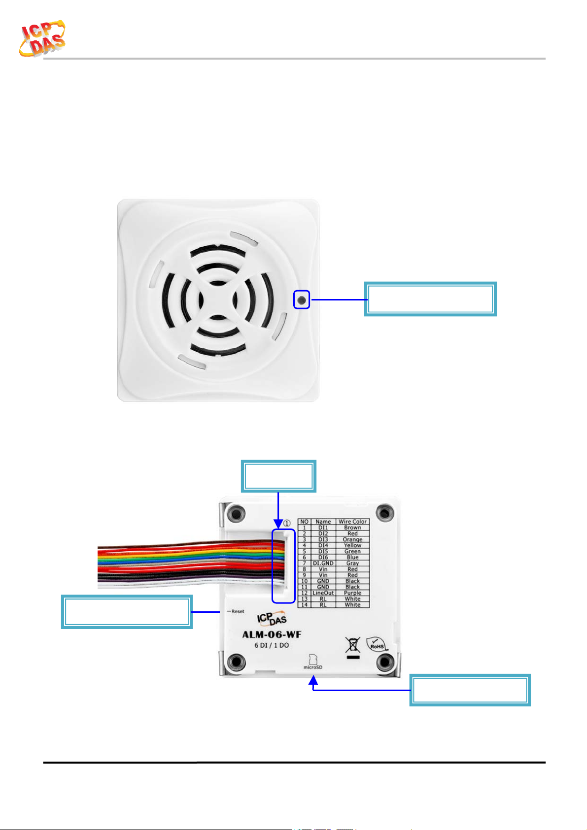
2.1 Outward Appearance
ALM-06-WF contains I/O connectors, Micro SD, Reset to Default and LEDs.
Power/Status LED
Reset to Default Switch
Figure 2-1: Front Panel
Connecto
Figure 2-2: Back Panel
Micro SD(T-Flash
ALM-06-WF User’s Manual (Rev1.0, Feb./2019) ------------- 9
Page 10
ALM-06-WF User’s Manual
2.1.1 LED Indicator
Table 2-1: System Status Indicator
System Status Indicator
LED Controller Status LED Status
Wi-Fi get Link
Power On Blue LED
PWR
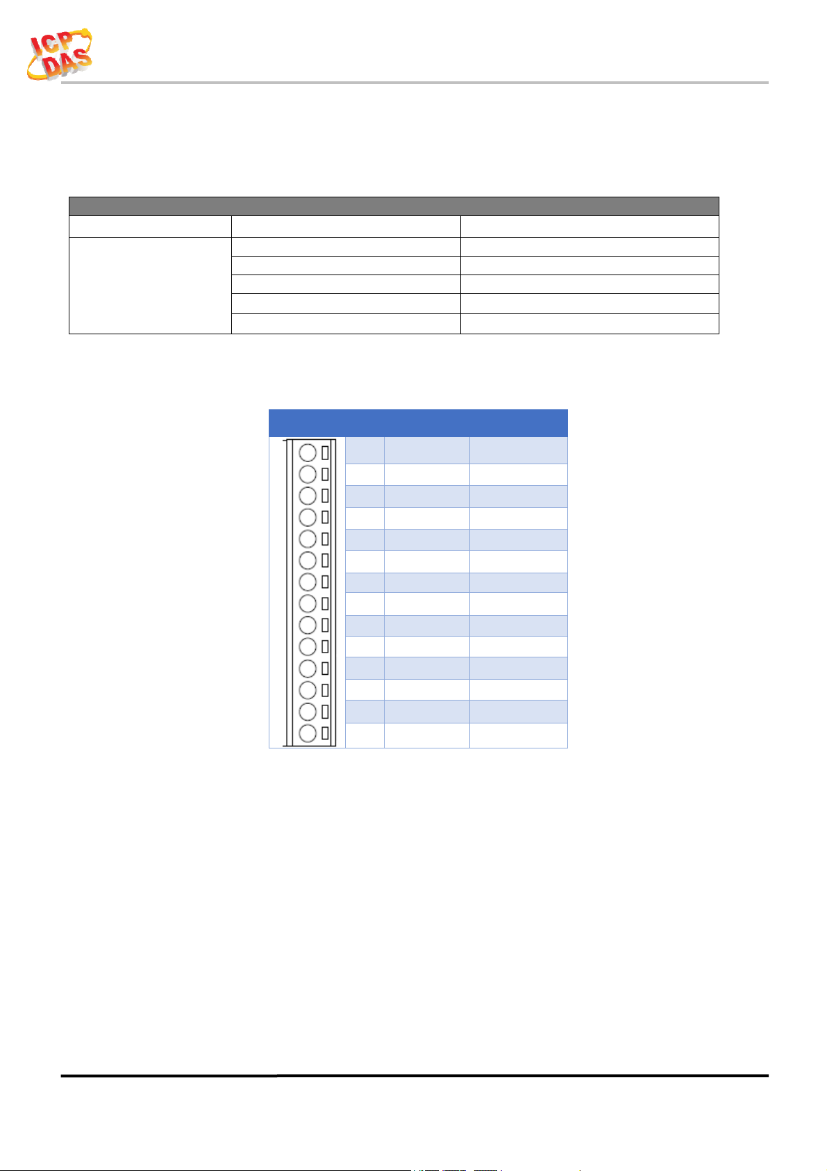
2.1.2 Connector Pin Define
Locator Red LED Blinking
Process reset to default Blue LED Blinking(Fast)
Alarm Status Red LED
Terminal NO Pin Name Wire Color
Purple(Blue + Red)
1 DI1 Brown
LED ON
2 DI2 Red
3 DI3 Orange
4 DI4 Yellow
5 DI5 Green
6 DI6 Blue
7 DI.GND Gray
8 Vin Red
9 Vin Red
10 GND Black
11 GND Black
12 Line Out Purple
13 RL White
14 RL White
Figure 2-3: I/O Connector of ALM-06-WF
ALM-06-WF User’s Manual (Rev1.0, Feb./2019) ------------- 10
Page 11
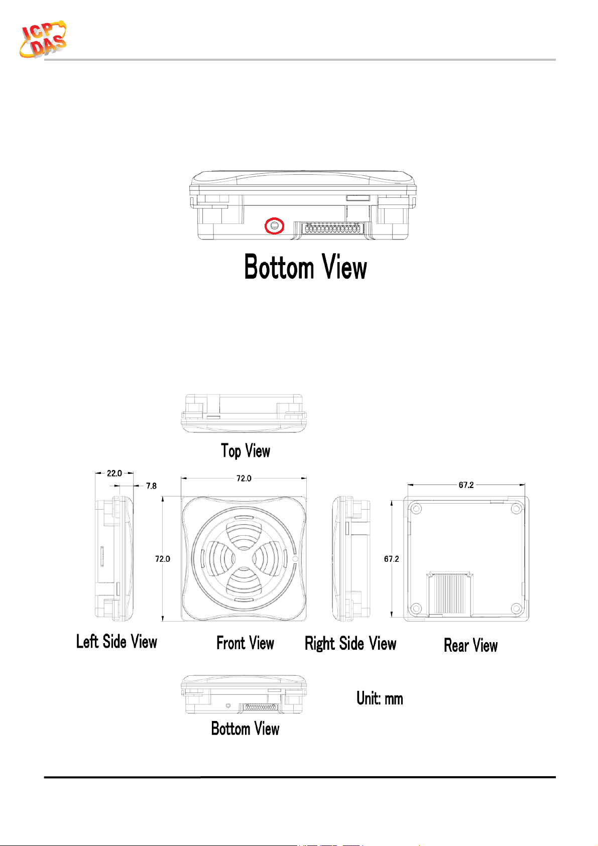
2.2 Reset to default
ALM-06-WF User’s Manual
Press & hold the reset button on the
LED quick flash then release to restore
bottom side over 6 Sec until the Red
ALM-06-WF default setting, default is
set in AP mode.
Figure 2-4: Reset button locate in the bottom side of ALM-06-WF
2.3 Dimensions
The diagrams below provide the dimensions of the ALM-06-WF to use in defining
your enclosure specifications. All dimensions are in millimeters.
Figure 2-5: Dimension of the ALM-06-WF
ALM-06-WF User’s Manual (Rev1.0, Feb./2019) ------------- 11
Page 12

ALM-06-WF User’s Manual
2.4 Wire Connection
2.4.1 Wire connection define
The following describe the wire color & function
2.4.2 I/O connection
2.4.2.1 Digital Input (DI) wiring
Figure 2-6: Wire color & function
Figure 2-7: DI Dry contact wiring
ALM-06-WF User’s Manual (Rev1.0, Feb./2019) ------------- 12
Page 13

ALM-06-WF User’s Manual
2.4.2.2 Relay Output wiring
Figure 2-8: Relay Output wiring
2.4.2.3 Line Out wiring
Figure 2-9: Line Out wiring
2.4.2.4 Power Input
Figure 2-10: Power Input
ALM-06-WF User’s Manual (Rev1.0, Feb./2019) ------------- 13
Page 14

ALM-06-WF User’s Manual
3. Software
The ALM Utility provides the simple way to operating and acquire I/O status.
ALM Utility can used the wireless network interface to configuration. Provide
AP(Access Point) & STA(Station) mode to connect the ALM-06-WF.
ALM Utility available on both Windows & Android application to operating and
configure the ALM-06-WF.
Utility Support Windows 7 (or later versions) and Android 5.0 (or later versions).
3.1 ALM Utility(AP Mode)
The following is the main screens provided by ALM Utility, these utility tools can be
thought as a useful tool for configuration and monitoring on the ALM-06-WF. It supplies
several functions, such as Monitoring, Configuration, Connection, Wi-Fi setting and F/W
upgrade, etc.., Only PC Utility support Audio & Alarm Configuration.
3.1.1
Main Screen
Figure 3-1: ALM Utility main screen
(From left to right is Windows Utility , Android App)
ALM-06-WF User’s Manual (Rev1.0, Feb./2019) ------------- 14
Page 15

ALM-06-WF User’s Manual
3.1.2 Controller Status
Show the connected controller information, user define Locate string, RSSI strength,
Device IP & Static IP button for changing device IP in STA mode.
3.1.3 DI/DO Status & Control
Show the DI/Relay Output status, The value can be read(DI) or set(Relay Output) in
this area.
Volume Control trackbar, range from 0(Mute)~10(Max).
Armed/DisArmed button for global alarm Enable/Disable.
Audio Configuration icon enter the configuration page (Only in PC Utility).
3.1.4 Status Bar
Show the F/W Version, Device’s Alarm mode, SD capacity, MAC address and
Device’s IP address.
ALM-06-WF User’s Manual (Rev1.0, Feb./2019) ------------- 15
Page 16

ALM-06-WF User’s Manual
r
3.1.5 Icon Button
ICON function
Setup
Open the Setup Screen (Android versions Setup
function under the
icon)
Find Controller
Refresh
Controlle
Refresh status
Only Android Device,
Red Led blinking, use to find the connected
Menu
Include setup, FW Version & About.
Audio
Configuration
Channel Test Simulation Channel Test. (Only in Android)
Audio Configuration page.
Table 3-1: icon Indicator
ALM-06-WF User’s Manual (Rev1.0, Feb./2019) ------------- 16
Page 17

ALM-06-WF User’s Manual
3.1.6 Configuration/Setup
Click apply icon
AP:
SSID Name
1. Default Controller’s SSID in Wi-Fi AP mode, will be ALM-06-xxxxxx.
Key Type
SSID Key
STA:
SSID Name
Figure 3-2: ALM Utility setup page
to save each subject’s setting, after finish all setting click
to make device take effect on new setting
Note: xxxxxx is the last 6 characters MAC address of your device.
AP mode SSID Key type (default is Open)
AP mode SSID Key, (default is None)
Wi-Fi AP’s SSID intent to connect (default is tWFHUB)
Key Type
Wi-Fi AP’s SSID Key Type (default is WPA/WPA2)
SSID Key
Wi-Fi AP’s SSID Key (default is 00000000)
ALM-06-WF User’s Manual (Rev1.0, Feb./2019) ------------- 17
Page 18

ALM-06-WF User’s Manual
Static IP:
IP: Specific an IP that is not been used.
Mask: Default will be 255.255.255.0.
Gateway: Basically define in the AP you are going to connect.
SSID
Key Type
Wi-Fi Mode:
Service Set Identifier: Connected devices must be the same SSID, SSID
length must not exceed 31 characters.
Key of Encryption, connected devices must with the same Key.
Open :No Key request.
WEP(Shared) :Key length must be 15 characters.
WPA/WPA2-PSK :Key length must between 8~15 characters.
Table 3-2: Station SSID & Key type configure
ALM Controller working mode (default is in AP)
AP (Access Point):
PC or Android Device connect to ALM Controller directly through
AP(Fixed IP:192.168.77.1), AP mode support only one connection, If Multiple
devices connect at a same time, only first connected devices can access.
STA(Station):
ALM Controller will auto connect to specific Wi-Fi AP, PC or Android
Device also need to connect to the same AP, then they can use those ALM
Controller in same domain.
*. Please check specific Wi-Fi AP is active and SSID/key is same as the setting
before use.
Location information:
Set the information for you to identify & locate those Controller easily, length
must under 31 characters.
Modbus Port:
Modify Modbus TCP Port (default is 502)
ALM-06-WF User’s Manual (Rev1.0, Feb./2019) ------------- 18
Page 19

ALM-06-WF User’s Manual
3.2 Station Mode (STA) IP scanner
There are lot of free IP scanner tools in both Windows & Android OS, for
example “Advanced IP Scanner” for Windows, “Network Analyzer” for Android,
those are high performance scanner tools on each OS.
ALM-06-WF User’s Manual (Rev1.0, Feb./2019) ------------- 19
Page 20

ALM-06-WF User’s Manual
k
k
3.3 Alarm Mode & Audio Editor
ALM-06-WF contain 8 kinds of alarm mode, Mode 0 ~ 3 are DI1~DI6 in single
independence channel trigger, in DIx channel priority, the priority of DI channel is
DI6 > DI5... > DI1.
Mode 4 ~ 7 are DI1~DI5 in Binary trigger & DI6 in single channel trigger, the
priority of DI channel in this mode is DI6 > 11111b(0x1F)>…> 00001b(0x01).
Alarm Mode
Mode Channel Trigger Function Mode Binary Trigger Function
0 General Playback 4 General Playback
1
2 Hold Repeat Playbac
3 Memory Once Playback 7 Memory Once Playback
Trigger Input priority Playback
Max 4 MP3 files can be add for each Channel or Binary trigger alarm, it will
playback from #1 to #4 for the trigger depend on the setting.
Relay output can set an extend alarm output to trigger other device.
All those setting can be done in PC Utility & can be monitor Armed/DisArmed
on both PC Utility or Android APP, show as below.
5 Trigger Input priority Playback
6 Hold Repeat Playbac
Figure 3-3: ALM-06-WF PC Utility Audio Editor page.
ALM-06-WF User’s Manual (Rev1.0, Feb./2019) ------------- 20
Page 21

ALM-06-WF User’s Manual
3.4 Start your Edit
Follow the step number,
(1) Select Job: Select Project or Device to Edit.
If Project Edit selected, you need to save project after finish edit.
In Device Edit selected, it will auto load the setting & audio file name from device,
same as Read Device button, in Device Edit mode audio file cannot be read back,
can only be modify or recover.
Write Device button will download all your setting & audio files into ALM-06-WF
device through Wi-Fi. Also you can copy all the file inside your project directory to
the Micro SD Card.
Volume Control trackbar, range from 0(Mute)~10(Max), same as main form.
To Create new project, use Load Project button, select the directory where you want
to put and add the new directory name, show as below.
Figure 3-4: New Project in Audio Editor.
ALM-06-WF User’s Manual (Rev1.0, Feb./2019) ------------- 21
Page 22

ALM-06-WF User’s Manual
(2) Add Audio: Double Click on which File No. you are going to add the audio file,
max 64 files can be assign.
File No. play back, select Play Source (Audio file original location) or Play Project
(Audio file in project) or Play Device (Audio file in ALM-06-WF device’s SD Card,
only when Device Edit selected), click File No. and press Play button to play, and Stop
button to break playback.
Click File No. and press the Delete button to remove file name in list, show as below.
Figure 3-5: Play Back & Delete File.
ALM-06-WF User’s Manual (Rev1.0, Feb./2019) ------------- 22
Page 23

ALM-06-WF User’s Manual
(3) Alarm Config: Frist you need to select Alarm Mode, then you can assign audio
File No. for each alarm channel from combo box, playback Repeat count & Alarm
Output Relay.
To simulation the alarm channel audio playback, select the channel from combo box,
press Channel test button to play, and Stop to break the playback, show as below.
Figure 3-6: Alarm Config Mode0~3 & Test Input.
Figure 3-7: Alarm Config Mode4~7 & Test Input.
ALM-06-WF User’s Manual (Rev1.0, Feb./2019) ------------- 23
Page 24

ALM-06-WF User’s Manual
3.4.1 Make a Micro SD from project
Copy all the file to the MicroSD root directory where your project directory locate,
this will be the same as Write Device from project.
3.4.2
To start a new MicroSD, please insert to a PC before use it, this will make Microsoft OS fill the
correct capacity into the MicroSD.
Insert a New MicroSD
ALM-06-WF User’s Manual (Rev1.0, Feb./2019) ------------- 24
Page 25

ALM-06-WF User’s Manual
3.5 Alarm Mode Description
Mode 0: Channel Trigger-General Playback
DI1 to DI6 playback in single independence trigger of 6 channels.
A pulse input triggered the Playback. Playback repeat when the input is not release.
When alarm in playback process, any input trigger will ignore.
The highest DIx channel priority input will take place after the previous playback complete.
Figure 3-8: ALM-06-WF Mode 0
Mode 1: Channel Trigger-Trigger Input priority Playback
DI1 to DI6 playback in single independence trigger of 6 channels.
When alarm in playback process, any trigger input will break & take place the previous
playback.
In this mode, it only playback once, even the input is not release.
Only when multi trigger in same time the highest DIx channel priority will take place
.
Figure 3-7: ALM-06-WF Mode 1
ALM-06-WF User’s Manual (Rev1.0, Feb./2019) ------------- 25
Page 26

ALM-06-WF User’s Manual
Mode 2: Channel Trigger- Hold Repeat Playback
DI1 to DI6 playback in single independence trigger of 6 channels.
When alarm in playback process, only higher DIx channel priority can break & take place the
previous playback.
Playback will repeat when input are not release & will stop immediately when input released.
When multi trigger in same time the highest DIx channel priority will take place
Figure 3-6: ALM-06-WF Mode 2
Mode 3: Channel Trigger- Memory Once Playback
DI1 to DI6 playback in single independence trigger of 6 channels.
When alarm in playback process, any trigger input will memory once for next playback.
In this mode, it only playback once, even the input is not release.
When multi trigger in same time the highest DIx channel priority will take place
Figure 3-7: ALM-06-WF Mode 3
ALM-06-WF User’s Manual (Rev1.0, Feb./2019) ------------- 26
Page 27

ALM-06-WF User’s Manual
Mode 4: Binary Trigger-General Playback
DI1 to DI5 are used as binary input, max 31 channels & DI6 in single channel.
A pulse input triggered the Playback. Playback repeat when the input is not release.
When alarm in playback process, any input trigger will ignore.
The highest binary channel priority input will take place after the previous playback complete,
DI6 is the most highest channel.
Figure 3-8: ALM-06-WF Mode 4
Mode 5: Binary Trigger-Trigger Input priority Playback
DI1 to DI5 are used as binary input, max 31 channels & DI6 in single channel.
When alarm in playback process, any trigger input will break & take place the previous
playback.
In this mode, it only playback once, even the input is not release.
The priority depend on trigger input, only when multi trigger in same time the highest binary
channel priority will take place, DI6 is the most highest channel.
.
Figure 3-9: ALM-06-WF Mode 5
ALM-06-WF User’s Manual (Rev1.0, Feb./2019) ------------- 27
Page 28

ALM-06-WF User’s Manual
Mode 6: Binary Trigger- Hold Repeat Playback
DI1 to DI5 are used as binary input, max 31 channels & DI6 in single channel.
When alarm in playback process, only highest binary channel priority can break & take place
the previous playback.
Playback will repeat when input are not release & will stop immediately when input released.
When multi trigger in same time the highest binary channel priority will take place, DI6 is the
most highest channel.
Figure 3-10: ALM-06-WF Mode 6
Mode 7: Binary Trigger- Memory Once Playback
DI1 to DI5 are used as binary input, max 31 channels & DI6 in single channel.
When alarm in playback process, any trigger input will memory once for next playback.
In this mode, it only playback once, even the input is not release.
The highest binary channel priority input will take place after the previous playback complete,
DI6 is the most highest channel.
Figure 3-11: ALM-06-WF Mode 7
ALM-06-WF User’s Manual (Rev1.0, Feb./2019) ------------- 28
Page 29

ALM-06-WF User’s Manual
4. Application
Users can use a Computer or Smart Device to communicate with the ALM devices in
the application. It can complete the purpose of control to wireless network by this way.
Figure 4-1: ALM + PC/Laptop/Smart Device application architecture
4.1 Connection with Modbus TCP utility
a. Open Modbus TCP utility and key in the IP address , Port as "502". Finally,
click the "Connect" button.
b. If the network settings are correct, this will immediately establish a
connection.
c. Use the function code "0x02", and set the Reference Number as "0x00", Bit
Count as "0x06" to get the 6 CHs DI value.
d.
Figure 4-2:Input Channels reading screen
ALM-06-WF User’s Manual (Rev1.0, Feb./2019) ------------- 29
Page 30

ALM-06-WF User’s Manual
e. Use the function code "0x01", and set the Reference Number as "0x00", Bit
Count as "0x01" to get the Relay Output value.
f.
Figure 4-3: Relay Status reading screen
g. Use the function code "0x05", and set the Reference Number as "0x00",
value as "0xFF" to turn on the Relay Output, & 0x00 to turn off.
h.
Figure 4-4: Relay output turn On/Off
ALM-06-WF User’s Manual (Rev1.0, Feb./2019) ------------- 30
Page 31

ALM-06-WF User’s Manual
5. Modbus Applications
The ALM-06-WF include a Modbus port that allows you to access terminals data
via Wi-Fi and communicates using a master-slave technique in which only one device
(the master) can initiate transactions (called queries). The other devices (slaves)
respond by supplying the requested data to the master, or by taking the action requested
in the query.
Most SCADA (Supervisor Control And Data Acquisition) and HMI software can
easily integrate serial devices via the Modbus protocol, such as Citect, ICONICS, iFIX,
InduSoft, Intouch, Entivity Studio, Entivity Live, Entivity VLC, Trace Mode, Wizcon,
Wonderware, etc.
For Android Device, a freeware HMI Modbus is easy to use.
5.1 What is Modbus TCP/IP?
Modbus is a communication protocol developed by Modicon in 1979.
Different versions of Modbus used today include Modbus RTU (based on serial
communication like RS485 and RS232), Modbus ASCII and Modbus TCP, which is the
Modbus RTU protocol embedded into TCP packets.
Modbus TCP is an internet protocol. The protocol embeds a Modbus frame into a
TCP frame so that a connection oriented approach is obtained thereby making it reliable.
The master query’s the slave and the slave responds with the reply. The protocol is
open and hence highly scalable.
ALM-06-WF User’s Manual (Rev1.0, Feb./2019) ------------- 31
Page 32

ALM-06-WF User’s Manual
5.2 Protocol Description
The Modbus protocol defines a simple protocol data unit independent of the
underlying communication layers. The mapping of Modbus protocol on network can
FCode
Data
(0 to 252 bytes)
introduce some additional fields on the application data unit.
Modbus/TCP Application Data Unit
Transaction ID
(2 bytes)
Protocol ID
(2 bytes)
MBAP Header Protocol Data Unit
Length
(2 bytes)
Unit ID
(1 bytes)
(1 bytes)
Figure 5-1: Modbus/TCP Application Data Unit
5.2.1 MBAP
The Modbus/TCP extension includes 7 additional bytes to the original Modbus
protocol, which allows for transport over the TCP/IP layers.
A dedicated header is used on TCP/IP to identify the Modbus Application Data
Unit. It is called the MBAP Header (MODBUS Application Protocol Header). The
MBAP Header consists of 7 bytes of information:
Fields
Transaction Identifier 2 bytes
Protocol Identifier 2 bytes 0 = Modbus protocol
Length 2 bytes Number of following bytes - Includes the Unit Identifier
Unit Identifier 1 byte Identification of remote slave
Length Description
Identification of Request/Response transaction – Copied
from request to response
Table 5-1: MODBUS Application Protocol Header
ALM-06-WF User’s Manual (Rev1.0, Feb./2019) ------------- 32
Page 33

ALM-06-WF User’s Manual
5.2.2 Function Code
The function code field of a Modbus data unit is coded in one byte. Valid codes are
in the range of 1 ... 255 decimal (the range 128 - 255 is reserved and used or exception
responses). When a Modbus request is sent from a Modbus Client to a Server device the
function code field tells the Server what kind of action to perform.
The Modbus/TCP feature of ALM series controller supports 6 function codes,
which allows the reading and writing of data contents of registers.
Function Code Descriptions
01 (0x01) Read Coil Status
02 (0x02) Read Input Status
03 (0x03) Read multiple Analog Output registers
05 (0x05) Force Single Coil
06 (0x06) Write single Analog Output registers register
16 (0x10) Write multiple Analog Output registers register
Table 5-2: Supports Function Codes of ALM series
Any other function code request will be returned with an error response indicating
the function code is not supported, as well as a request for too much data or data at a
register address that not present.
5.2.3 Data
The data field of Modbus request sent from a client to server devices contains
additional information that the server uses to take the action defined by the function
code. This can include items like discrete and register addresses, the quantity of items
to be handled, and the count of actual data bytes in the field.
The data field may be nonexistent (of zero length) in certain kinds of requests, in
this case the server does not require any additional information. The function code
alone specifies the action.
ALM-06-WF User’s Manual (Rev1.0, Feb./2019) ------------- 33
Page 34

ALM-06-WF User’s Manual
5.2.4 Response
If no error occurs related to the Modbus function requested in a properly received
Modbus PDU (Protocol Data Unit) the data field of a Modbus response from a server to
a client contains the data requested. If an error related to the Modbus function requested
occurs, the field contains an exception code that the server application can use to
determine the next action to be taken.
For example a client can read the ON/OFF states of a group of digital input or
output or it can read/write the data contents of a group of registers.
When the server responds to the client, it uses the function code field to indicate
either a normal response or that some kind of error occurred (called an exception
response). For a normal response, the server simply echoes to the request the original
function code.
For an exception response, the server returns a code that is equivalent to the
original function code from the request PDU with its most significant bit set to logic 1.
5.2.5 Data Encoding
Modbus uses a “big-endian” representation for address and data items. This means
that when a numerical quantity larger than single byte is transmitted, the most
significant byte (MSB, also called the high-order byte) is send first. The following subtopics describe the different byte of encoding and show how the data is encoded as it is
within the Modbus/TCP packet.
5.2.5.1 Binary
A binary item is represented as a single bit within a data word. All binary is packed
into 16-bits data words, which are accessed using function code 01 and 02. Therefore, a
single register contains 16 bits of binary data, each having a specific meaning.
Value 1st 2nd
0xAA55
(1010101001010101)
0xAA
(10101010)
0x55
(01010101)
Table 5-3: A single register contains 16 bits of binary data
ALM-06-WF User’s Manual (Rev1.0, Feb./2019) ------------- 34
Page 35

ALM-06-WF User’s Manual
5.2.5.2 16-bits Word
A 16-bits word item is transmitted with the most significant byte first. Function
code 03 and 04 read 16-bits items at a time; therefore, each of these data items will fit
within one register that is read.
Value 1st 2nd
0x1234 0x12 0x34
Table 5-4: A 16-bits word item
5.2.5.3 32-bits Double Word
A 32-bits word item is transmitted with the most significant byte first. Function 04
read 32-bits items at a time; therefore, each of these data items will fit within 2 register
that is read.
Value 1st Word 2nd Word
0x12345678 0x5678 0x1234
Table 5-5: A 32-bits double word item
5.3 ALM-06-WF Address Mapping
Address CH Descriptions Range Access Type
00001 1 Digital Output 0=OFF, 1=ON R
00002 2 ARMED Status 0=OFF, 1=ON R
Table 5-6: FC01 Read DO address (0xxxx)
Address CH Descriptions Range Access Type
10001~10006 1~6 Digital Input 0=OFF, 1=ON R
Table 5-7: FC02 Read DI address (1xxxx)
ALM-06-WF User’s Manual (Rev1.0, Feb./2019) ------------- 35
Page 36

ALM-06-WF User’s Manual
Address CH Descriptions Range Access Type
40001 1 Volume Level (0~10) INT16 R
Table 5-8: FC03 Read multiple AO address (4xxxx)
Address CH Descriptions Range Access Type
00001 1 Relay Output 0x00=OFF, 0xFF=ON W
00002 2 ARMED 0x00=OFF, 0xFF=ON W
00003 3 Stop Playback 0xFF=Stop Playback W
00009~00014 1~6 Simulation Channel Test 0xFF=Run Test W
Table 5-8: FC05 Write DO address (0xxxx)
Address CH Descriptions Range Access Type
40001 1 Volume Level (0~10) 16bit Word W
Table 5-9: FC06 Write single AO address (4xxxx)
Address CH Descriptions Range Access Type
40001 1 Volume Level (0~10) 16bit Word W
Table 5-10: FC16 Write multiple AO address (4xxxx)
Technical Support
If you have problems about using the ALM-06-WF controller, please contact ICP DAS
Product Support.
Email: service@icpdas.com
ALM-06-WF User’s Manual (Rev1.0, Feb./2019) ------------- 36
 Loading...