

Page 1
ACS-11P-MF Quick Start v1.0 2017/08
1/8
Quick Start
「 ACS-11P-MF」Package Checklist
The package includes the following items:
One ACS-11P-MF module
One Quick Start
One software utility CD
Cables(CA-012x2, CA-013x1, CA-019x1, CA-020x1)
Note:
If any of these items are missed or damaged, contact the local distributors
for more information. Save the shipping materials and cartons in case you
want to ship in the future.
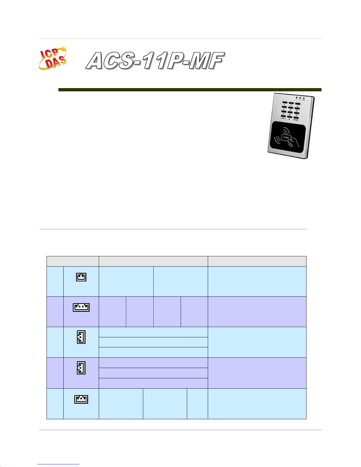
Pin assignments
Table 1: Connector Pin Assignment
Connector Type
Pin Assignment
Description
CN1
(CA-019)
D+
D-
RS-485(D+/D-)
Baud Rate (bps): 9600
Parity: NONE, Data Bits: 8, Stop Bits: 1
CN2
(CA-020)
DI0 G DI1
G
DI0(Door position detection)
DI1(Electric lock trigger)
(Digital Input, Dry Contact)
CN3
(CA-012)
NC
Electronic lock control
(Relay Output)
COM
NO
CN4
(CA-012)
NC
Door position alarm output
(Relay Output)
COM
NO
CN5
(CA-013)
COM
NO
NC
Anti-sabotage detection
(Relay Output)
Page 2
ACS-11P-MF Quick Start v1.0 2017/08
2/8
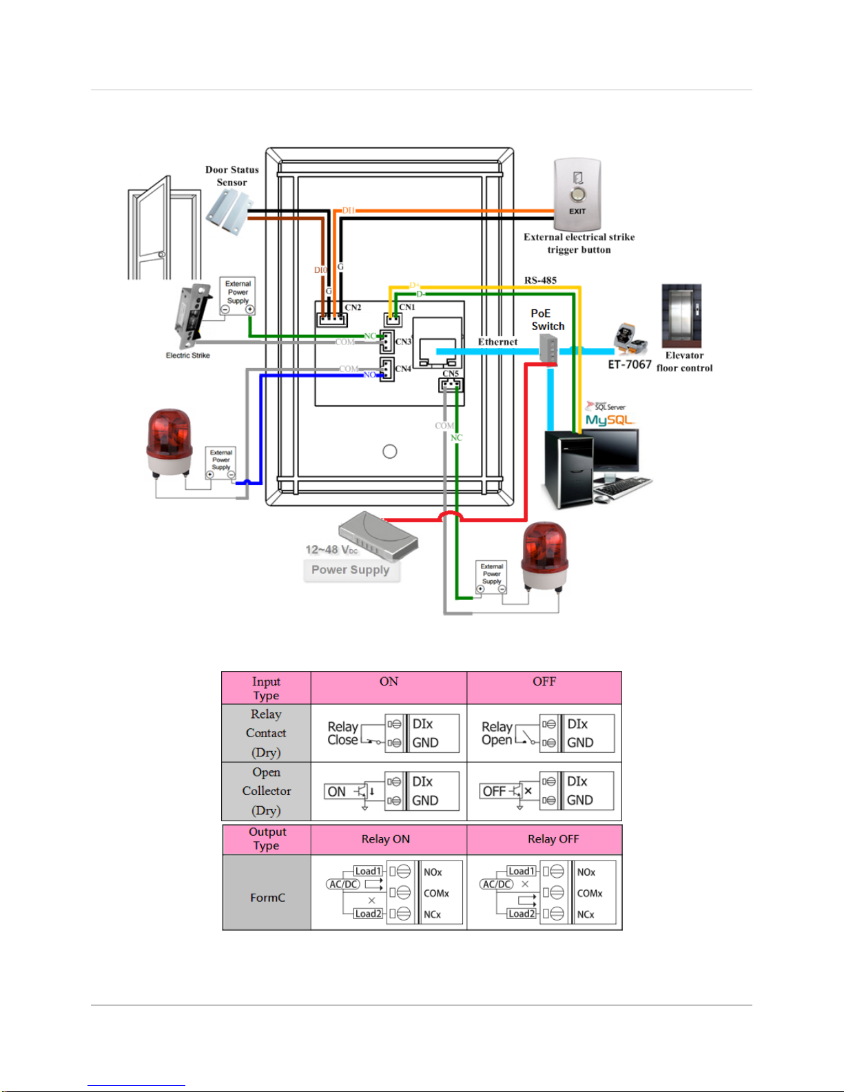
Hardware Installation
Figure 1: Wiring diagram
Figure 2: Wire connection
Page 3
ACS-11P-MF Quick Start v1.0 2017/08
3/8
Software Installation
Before use, associated software configuration, the steps described as
follows:
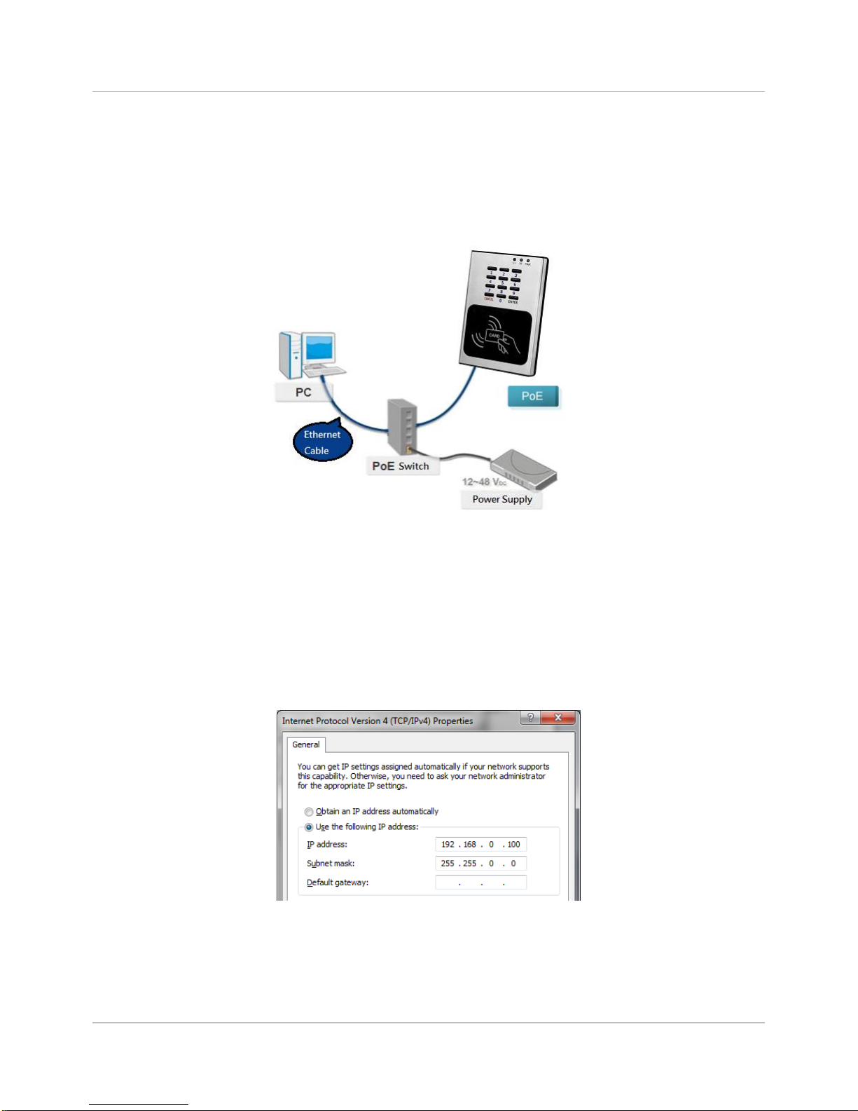
Connect to host PC, network and power supply
Figure 3: Host PC, Network and Power supply
01. Make sure that the network settings on the PC are properly configured
and functioning properly
a. Entry the IP address as "192.168.0.x", where "x" is a number
Between 1 and 254 except 1, Subnet mask as "255.255.0.0".
Finally, press "OK" button.
Figure 4: IP address configuration of Computer
02. Make sure that Windows Firewall or antivirus firewall is properly
configured to allow incoming connections, or temporarily disable these
features
Page 4

ACS-11P-MF Quick Start v1.0 2017/08
4/8
Execute access control setting program (ACS Config Utility)
01. ACS Config Utility can be obtained either from the companion CD or from
the ICP DAS FTP site at
http://ftp.icpdas.com/pub/cd/ba-ha/acs/acs-11-mf-tc/software/utility/
02. Click the "Search" button to search for your module
Figure 5: The main screen of the ACS Config Utility
03. Select network connection interface of PC
04. Click the "OK" button to wait for the search to complete
Figure 6: Select network connection interface
05. Display the device search list and select the module name
Figure 7: Device search list
Page 5

ACS-11P-MF Quick Start v1.0 2017/08
5/8
Add Mifare card number and Pass password
Figure 8: Add card number and password setting screen
A. Add Mifare card number
01. Select the voice number (0~39): 0
02. Floor control options: Check (enable) / Uncheck (disable)
03. Fill in the UID of card: 2632646384(4 Byte or 7 Byte UID)
04. Click the "Add UID" button
05. Display "Reply OK"; make sure to add the UID successfully
B. Add pass password
01. Select the voice number (0~39): 0
02. Floor control options: Check (enable) / Uncheck (disable)
03. Fill in the pass password: 1234(4 digits number)
04. Click the "Add PWD" button
05. Display "Reply OK"; make sure to add the pass password successfully
C. Mifare card induction test
01. Place the Mifare card close to the ACS-xxx-MF
02. ACS-xxx-MF will read the card UID and record the pass information
03. ACS-xxx-MF will open the electronic lock relay (CN4) and play the
specified voice
D. Pass password test
01. Enter the pass password in the ACS-xxx-MF keypad area, and press the
"OK" button
02. ACS-xxx-MF will read the pass password and record the pass information
03. ACS-xxx-MF will open the electronic lock relay (CN4) and play the
specified voice
01
02
03
04
05
Page 6

ACS-11P-MF Quick Start v1.0 2017/08
6/8
E. Read the pass records
01. Click the "Get Record" button to read a pass record
02. Display Card number [2632646384] / Pass password [1234]、
Status [Pass] and Time [Year/Month/day Hour:Minute:Second]
Figure 9: Read screen of pass records
Delete Mifare card UID and Pass password
Figure 10: Delete card number and password setting screen
A. Delete Mifare card UID
01. Fill in the UID of card: 2632646384(4 Byte or 7 Byte UID)
02. Click the "Del UID" button
03. Display "Reply OK"; make sure to delete the UID successfully
01
02
Password
Card UID
02
01
01
02
Page 7

ACS-11P-MF Quick Start v1.0 2017/08
7/8
B. Delete pass password
01. Fill in the pass password: 1234(4 digits number)
02. Click the "Del PWD" button
03. Display "Reply OK"; make sure to delete the pass password successfully
C. Mifare card induction test
01. Place the Mifare card that has deleted the card number close to the ACSxxx-MF
02. ACS-xxx-MF will read the card UID and record the pass information
03. ACS-xxx-MF will play "Invalid Card" voice
D. Pass password test
01. Enter the pass password in the ACS-xxx-MF keypad area, and press the
"OK" button
02. ACS-xxx-MF will read the pass password and record the pass information
03. ACS-xxx-MF will play "Invalid Password" voice
E. Read the pass records
01. Click the "Get Record" button to read a pass record
02. Display Card number [2632646384] / Pass password [1234]、
Status [Denied] and Time [Year/Month/day Hour:Minute:Second]
Figure 11: Read screen of pass records
01
02
Password
Card UID
02
01
Page 8

ACS-11P-MF Quick Start v1.0 2017/08
8/8
Troubleshooting
Item
Problem Description
Solution
1
Power Failure
(PWR LED Off)
1. Please return to the ICP DAS for inspection and
repair
2
Cards can not be used
1. Make sure cards support Mifare S50 standard
( ISO 14443-A)
2. EM and HID cards are not supported
3
How to find out IP address of
ACS-xxx-MF?
1. Entry the default IP operation mode
Step1. Press and hold the No. 1 key
Step2. Reset the power of ACS-xxx-MF
Step3. Now the PWR led flashes and IP address
is "192.168.0.1"
Step4. Enter the settings web page then find out
IP address
2. Use eSearch Utility
Step1. Launch eSearch.exe
Step2. Press "Search Servers" button then find
out IP address
Technical Support
If you have problems about using the ACS series module, please
contact ICP DAS Product Support.
Email: service@icpdas.com
 Loading...