

Page 1

WS-855A
User Manual
Version 2.2
<Product Overview>
15” TFT Display
10-slot Workstation
January 20, 2004
Page 2

1
Copyright Notice
© Copyright 2004 by ICP Electronics Inc. All rights reserved.
No part of this manual may be reproduced, copied, or translated without prior
notice to ICP Electronics Inc.
The information provided in this document is for reference only. We do not
assume any responsibility arising out of the application of the products. This
manual is subject to change without any notice.
WS-855A and ICP is trademark of ICP Electronics Inc.
Page 3

2
Table of Contents
Chapter 1. Product Information ........................................ 3
1.1. General Information................................................ 3
1.2. Product Specifications ............................................. 4
1.3. Dimensions............................................................ 6
1.4. Front Accessible CD-ROM, 3.5" FDD .......................... 7
1.5. The Membrane Keypad ............................................ 8
Chapter 2. System Setup .................................................. 9
2.1 Adding Cards ......................................................... 9
2.2 Disk Drives installation ............................................ 9
2.3 Power Supply Installation....................................... 11
2.4 Cooling Fan Installation ......................................... 12
2.5 Panel Mounting..................................................... 13
2.6 Rack Mounting ..................................................... 14
Chapter 3. Maintenance .................................................. 15
3.1 Power Supply....................................................... 15
3.2 Cooling Fan.......................................................... 15
3.3 Disk Drives .......................................................... 15
Appendix B Keypad........................................................... 17
A. Block Diagram............................................................. 17
B. Jumper Setting............................................................ 17
Appendix C User Mode OSD Item Description................... 19
Appendix D Touch Panel Controller................................... 22
Appendix E Touch Pad ...................................................... 23
Appendix F CHECK LIST ................................................... 24
Page 4

3
Chapter 1. Product Information
1.1. General Information
The WS-855A series workstations take advantage of modern flat-panel display,
CPU board, power supply and passive backplane for minimum size. It is an IBM
PC/AT compatible computer specially designed to meet the applications for
industrial working environments.
LCD Display
WS-855A is equipped with a color 1024x768 resolution 15" TFT LCD.
Versatile Passive Backplane
WS-855A can be equipped with PCI-10S (standard), PCI-10S2, BP-10S,
IP-10S or PX-10S 10-slot backplane.
Sealed-membrane Accessible Keypad
The sealed-membrane keypad has 59 data keys including 10 function keys to
allow users enter data directly. Users also can attach the external keyboard
through a connector on the front panel of WS-855A.
Power Switch, Ext. Keyboard and USB Port
The front lockable drive door protects the Power switch, Ext. board and the
USB port.
Optional Touch Screen
Touch Screen: Analog resistive type with RS-232 interface controller.
Power Supply
WS-855A is equipped with ACE-832A, 300W ATX industrial power supply.
Optional Power Supplies
ACE-925T/932T/828T –48VDC input
ACE-925C/828C +24VDC input
ACE-916V +12VDC input
Dimensions
483(W)x354(H)x265(D)mm.
Page 5

4
Product Specifications
Front Panel: Aluminum meets NEMA 4 or IP65.
8U Height, rack-mount or panel-mount with front LCD on/off switch.
Disk Drive Bay: Support one 5.25" Drive CD-ROM, one 3.5" FDD and one 3.5" HDD.
59 entry keys including 10 function keys.
Lockable drive door design & anti-vibration card clamp included.
Backplane: PCI-10S (standard), PCI-10S2, BP-10S, IP-10S, PX-10S 10-slot backplane.
12cm ball bearing cooling fan with removable fan filter.
Display Module
SPEC IFICATIONS WS-855A
LCD Type AU-15.0” XGA Color TFT-LCD
Single Supply Voltage +12 VDC
Panel Size 15” Diagonal
Viewing Area 304.1mm x 228.1mm
Number of Pixels 1024 (W) x 768 (H)
Pixel Format 1 pixel = R + G + B dots
Pixel Arrangement R, G, B Vertical Strip
Pixel Pitch 0.297mm (H) x 0.297mm (V)
LCD Display Colors 262K, 18bits
Brightness 250 cd/m2
Viewing Direction 6 o’clock (in direction of max. contrast)
Viewing Angle 60˚ (LEFT), 60˚(RIGHT), 40˚ (UP), 40˚ (DOWN)
Contrast Ratio > 400:1
Surface Treatment Anti-glare and Hard Coat 3H
Backlight Twin cold-cathode fluorescent lamps for side
lighting
Operating Temperature 0~50 ℃
Storage Temperature
LCD MTBF 50,000 hours
Backlight MTBF 25,000 hours (min)
Input VGA Input
OSD OSD built
Dynapro Touch Screen (Optional)
Type: Analog Resistive
Resolution: Continuous
Light transmission: Typical value 72%
Surface Hardness: 4H (Test condition: ASTM D3363-92A)
8-wire touch screen
Support driver: Supports DOS, Windows 3.1, 95, 98, 2000, NT.
Page 6

5
Industrial Power Supply
Power Supply: ACE-832A, 300W industrial power supply
Shock: 10 G peak acceleration (11 msec. duration)
Safety: meet UL/CSA/TUV
EMI: meet FCC/VDE class A
Environmental Specifications
Operating Temperature : 0 ~ 50℃
Relative Humidity: 10-95% @40 ℃ , non-condensing
Vibration: 5 to 17 Hz, 0.1"double-amplitude displacement,
17 to 500 Hz, 1.5 G Peak to peak
Page 7

6
1.2. Dimensions
The following diagram indicates the dimensions of WS-855A.
'
`
2
7
9
.
4
483
7
6
.
2
2
5
5
2
1
1
413.4
265
10
3
3
4
443
3
5
4
Page 8

7
1.3. Front Accessible CD-ROM, 3.5" FDD
WS-855A workstation is equipped with one 5.25˝CD-ROM and 3.5˝ FDD that can
be accessible by opening the front lockable drive door as shown in the following
diagram. Power ON/OFF switch, Ext.-keyboard and USB port are also accessible
through this same front lockable drive door.
** For detail OSD item description, please refer to Appendix C User
Mode Operation.
`
'
Page 9

8
1.4. The Membrane Keypad
The sealed-membrane keypad has 59 keys including 10 function keys to allow
users enter data directly. Users can also attach the external keyboard through a
connector on the front panel of WS-855A. A built-in controller will merge the
signals from the membrane keypad and general keyboard into one signal, which
acts as a standard IBM PC/AT keyboard.
'
`
Page 10

9
Chapter 2. System Setup
The WS-855A 15" TFT LCD 10-slot workstation is very easy to set up for
operation. All you have to do is to open the back cover, install your CPU card,
display control card, hard disk drive and other I/O cards required by your
application, and you are ready to mount into a 19" rack or within a panel and
start to operate.
2.1 Adding Cards
Before installing the cards, the rear cover should be removed first by releasing
the screws as illustrated in the diagram below. Then, users can slowly slide the
card in and carefully press it into the slot of backplane. Please use the clamps
shown in the diagram to affix your cards.
2.2 Disk Drives installation
WS-855A is equipped one 5.25" Drive CD-ROM, one 3.5" FDD and one 3.5" HDD
which should be installed from the rear of chassis. Users must use the clamps to
fix 5.25˝CD-ROM, 3.5˝FDD and 3.5˝HDD. Please refer to the diagrams below.
Card Clamp
Holdin g CLAMP
FOR:ISA-CARD
FOR :PCI-CARD
Page 11

10
Please install the drivers in the order shown in the diagrams below.
F
D
D
H
D
D
C
D
-
R
O
M
STEP 2
STEP 2
STEP 2
STEP 3
STEP 3
STEP 3
Page 12

11
2.3 Power Supply Installation
Power supply is equipped at the rear of workstation and some screws are
available to fasten it as shown below.
STEP 1
STEP 2
STEP 3
STEP 3
PS ON
BACKPLANE
WHITE
BLUE
BLACK
BROWN
P9
P8
P8
BACKPLANE
ACE-925A
POWER
SUPPLY
GND
Brown
Blue
White
Black
Brown
Blue
Black
White
1
7
P9
RED
BLACK
1
2
3
To: CPU card
To: CPU card
DUPONT
Button SW
BLACK
YELLOW
RED
Molex:5051-3
O
I
DUPONT
ACE-832A
SUPPLY
POWER
(ATX)
Page 13

12
2.4 Cooling Fan Installation
WS-855A is equipped with a 12 cm ball bearing cooling fan with removable fan
filter by the side of workstation. The following diagram shows the details of fan
and its accessories.
STEP 1
STEP 2
UNIT OF FILTER SETTING
12cm FAN
PCB GUIDE RAIL
Page 14

13
2.5 Panel Mounting
WS-855A can be mounted within a panel as shown in the following figure. Please
make sure that the dimensions of the case is within panel aperture so that your
screw holes line up with the mounting bolts on the flange of WS-855A.
Page 15

14
2.6 Rack Mounting
WS-855A can not only be mounted within a panel but also can be mounted in a
19" Rack. The following diagram shows how to mount WS-855A into the 19"
Rack.
Page 16

15
Chapter 3. Maintenance
There are some essential points that you need to know during maintenance or
upgrading process.
3.1 Power Supply
Please refer to the diagram of section 2.3 to unfasten the four screws so as to
take the power supply out for maintenance or upgrade.
Warning: Be sure to switch off the power supply and unplug the power cord
before you take off a part for either maintenance or upgrade.
3.2 Cooling Fan
WS-855A is equipped with 12 cm cooling fan with removable fan filter by the side
of the workstation. Please refer to the diagram of section 2.4. You have to open
the chassis and unfasten the four bolt kits to take the fan out for maintenance.
The filter is suggested to be replaced or cleaned at appropriate time depending on
the type of working environment the workstation is posted.
Warning: Do not use the wet filter to filter out the dirt.
3.3 Disk Drives
WS-855A is equipped with one 5.25" CD-ROM, one 3.5" FDD and one 3.5" HDD.
Please refer to the diagram of section 2.2 to uninstall 5.25" CD-ROM, 3.5" HDD
and 3.5" FDD.
Page 17

16
Appendix A Exploded Diagram
ITEM DESCRIPTION PART NO. QTY REMARK
1 Front Panel 42001-0025XX 1
2 59key pad membrane 42002-0011XX 1
3 Lockable front door 52100-000007 1
4 Touch pad units 19700-000003 1
5 OSD membrane 52100-000007 1
6 15” TFT LCD CPT-CLAA150XA03 23000-000037 1
7 Lock 45007-000104 1
8 Strengthened glass 15” 48113-333257 1 Optional
9 Front panel bracket 41002-0035XX 1
10 Display Bracket 41017-010702 1
11 Cover plate 41022-0007XX 1
12 KBD-01 Board 131KBD01-00-011 1
13 Back panel bracket 41003-0011XX 1
14 Power supply / ACE-832A ACE-832A 1 Optional
15 Lead CG-9A 46002-000200 7
16 Fan bracket 41009-0003XX 1
17 Filter bracket 41010-0003XX 1
18 Fan 12cm, 2 wire 31100-000018 1
19 Unit filer 46016-000400 1
20 Slide for driver 41021-000100 6
21 Rear cover screw 42005-000204 2
22 Rear cover 41022-0006XX 1
23 Card clamp 41015-0016XX 1
24 Driver bay (FDD + HDD) 41011-0024XX 1
25 Driver bay (CD-ROM) 41011-0025XX 1
26 PCI-10S PCI-10S 1 Optional
27 Bracket-10S 41005-0071XX 1
28 Power bracket 41024-0003XX 1
1
2
3
4
7
5
8
9
6
10
11
12
13 14
15
16
17
18
19
20
21
22
23
24
25
26
27
28
Page 18

17
Appendix B Keypad
A. Block Diagram
B. Jumper Setting
CON1
Pin1 Pin2 Pin3 Pin4 Pin5
+5V in GND GND DATA CLOCK
CON2
Pin1 Pin2 Pin3 Pin4 Pin5
+5V in GND GND DATA CLOCK
CON3
Pin1 Pin2 Pin3 Pin4 Pin5
+5V in GND GND DATA CLOCK
A203
Membrane 1
Membrane 2
Keyboard 1
Keyboard 2
PC
CON1
J
P4
CON2
CON
JP3
JP1
Page 19
18
JP3
Pin1 Pin2 Pin3 Pin4 Pin5
BTN0 BTN1 BTN2 BTN3 BTN4
Pin6 Pin7 Pin8
BTN5 BTN6 BTN7
JP1
Pin1 Pin2 Pin3 Pin4 Pin5
LINE0 LINE1 LINE2 LINE3 LINE4
Pin6 Pin7 Pin8 Pin9 Pin10
LINE5 LINE6 LINE7 POWER GOOD
LED- out
+5V in
Pin11 Pin12 Pin13
SCROLL LED
DRIVER out
NUM LED DRIVER
out
CAPS LED
DRIVER out
JP4
Pin1 Pin2 Pin3 Pin4 Pin5
BTN0 BTN1 BTN2 BTN3 BTN4
Pin6 Pin7 Pin8 Pin9 Pin10
BTN5 BTN6 BTN7 NC LINE8
Pin11 Pin12
LINE9 LINE10
JP2
Membrane JP2 (1-2)
52100-000182
52100-000183
OPEN
52100-00007
52100-000103
52100-000183
SHORT
Page 20

19
Appendix C User Mode OSD Item Description
Auto-Adjustment
This item will automatically adjust the H/V position, frequency, phase, and
black level.
Auto Phase
This item will automatically adjust the sampling.
Brightness
This item is used to adjust the brightness of screen. This function will also
adjust the offset value of ADC. Setting this value too high or too low will
destroy the quality of image.
Contrast
This item is used to adjust the contrast of screen. This function will also
adjust the gain value of ADC. Adjust this value too high or too low will
destroy the quality of image.
Page 21

20
DOS/GFX
It is used to select VGA input signal to either text mode or graphic mode.
(This item is only selectable on resolution of 720/640x400 or 720/640x350.)
400 and 350 standard IBM modes have the same Hsync. and Vsync. Values
so AV-9261 MPU cannot differentiate them automatically. For these modes,
users need to adjust them manually so as to match proper VGA mode.
H. Position
It is used to adjust horizontal display position of image.
V. Position
It is used to adjust vertical display position of image.
Language
It is used to select the languages using on OSD display. AV-9261 now can
support 2 languages on OSD display. English is the default language.
Page 22

21
Revert
It is used to reload original parameters from the factory’s OSD data area of
the system EEPROM 24c16 device to re-initialize AV-9261 system device.
When user adjust OSD data too much and did not gain better quality, user
can select this item and MPU will reload default BIOS setting and re-initialize
the system.
Save
It is used to save the parameters into the user OSD adjustment data area of
the system EEPROM 24c16 device and close OSD. Whenever users adjust any
parameters, it is needed to execute this item to save data into EEPROM. And
the next time you turn system’s power on, the MPU will use the stored data
to initialize the AV-9261 system.
Main Menu
Every level of OSD have the item name Main Menu, this item enables user
to leave current level and jump to upper level, or press you can press the
Return key.
Exit
Press EXIT key to exit OSD menu when OSD menu is on top of the level.
Page 23
22
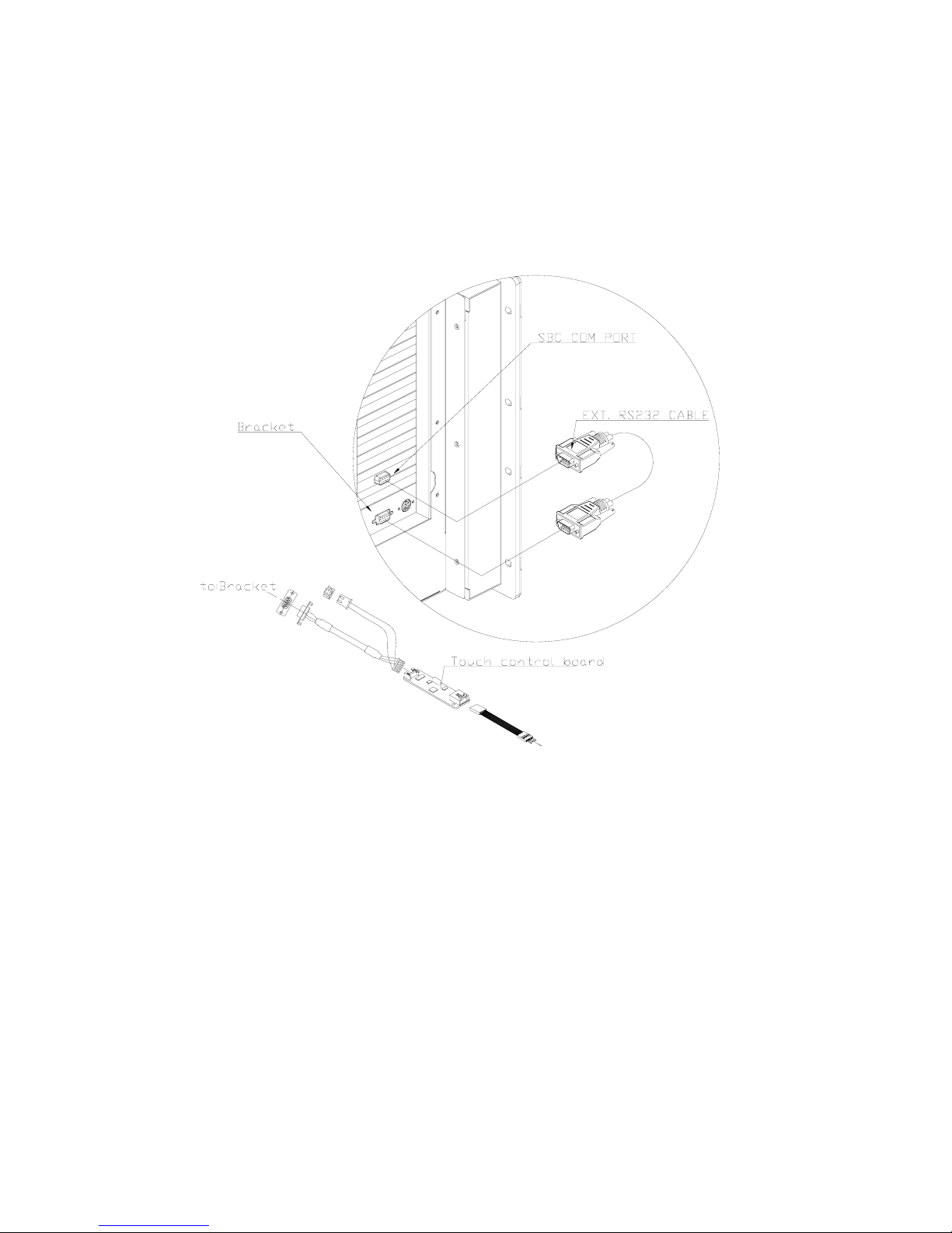
Appendix D Touch Panel Controller
Please refer to the following diagram for graphic illustration of how connection of
touch panel controller is done.
+
5
V
G
N
D
Touch screen
Page 24

23
Appendix E Touch Pad
TP-101 Touch Pad is PS/2 Mouse compatible. Users must connect the external
PS/2 Mouse cable as the in the figure below. Touch Pad is a pointing device for
computers and it detects the position of a finger over a touch-sensitive area. To
move the cursor, users have to lightly slide a finger over the smooth sensor area.
To “ click”, gently tap on the surface. This action is the same as clicking the left of
a mouse. If you “double click” it, the system will execute an operation.
TP-101 Assembly
Page 25

24
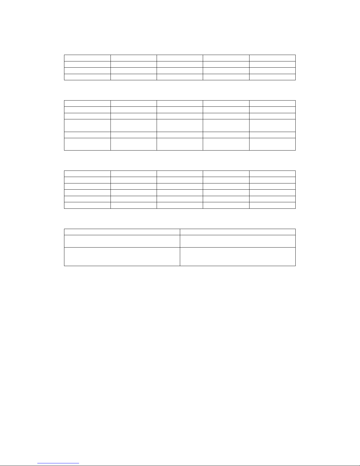
Appendix F CHECK LIST
ITEM
PART NO.
DESCRIPTION
Q’TY REMARK
1 32000-000002 ROUND CABLE.POWER CORD 175CM. 1 By POWER SUPPLY
2 32000-023200
ROUND CABLE.VGA CABLE M TO M. 15PIN
TO 15PIN.25CM.
1 By VGA CABLE
3 32000-000072 ROUND CABLE.MINI DIN M TO M (27.5CM) 2
By Touch pad to CPU
CARD x1
By KEYBOARD x1
4 32000-000050 D_SUB 9PIN F TO M/50M 1
For: Touch screen
(OPTIONAL)
5 41015-000302 HOLDING CLAMP (SHORT).. 4 By CARD CLAMP
6 41015-000402 HOLDING CLAMP (LONG) 3 By CARD CLAMP
7 19600-000003 UNIT SCREW WS serial.
7-1 44003-030061 SCREW.M3*6 10
7-2 44003-632041 SCREW.6#32*4 10
7-3 44003-632061 SCREW 6#32*6 10
7-4 44013-030061 SCREW PLATE.M3*6 10
7-5 44013-632041
SCREW PLATE 6#32*4.Φ5mm
5
7-6 44310-632061 Bronze Stick.6#32*6. H=5mm 12
7-7 44033-030061 SCREW M3*6... 10
7-8 44033-040062 SCREW M4*6. 10
1
4
2
3
7
6
54
 Loading...