

Page 1
NOTE: Read the entire instruction manual before starting
installation.
TABLE OF CONTENTS
PAGE
SAFETY CONSIDERATIONS ........................... 1
INTRODUCTION ...................................... 1
INSTALLATION ....................................... 1
CHECK EQUIPMENT .................................. 1
MOUNT FAN COIL .................................... 2
DUCTWORK SPECIFICATIONS ......................... 3
CONDENSATE DRAIN ................................. 3
FIELD INSTALLATION OF CONTROLS .................. 3
ELECTRICAL CONNECTIONS .......................... 3
SELECT PROPER BLOWER SPEED .................... 4
START-UP ........................................... 4
CARE AND MAINTENANCE ............................ 4
AIRFLOW PERFORMANCE ............................ 4
SAFETY CONSIDERATIONS
Improper installation, adjustment, alteration, service,
maintenance, or use can cause explosion, fire, electrical shock,
or other conditions which may cause death, personal injury or
property damage. Consult a qualified installer, service agency,
or your distributor or branch for information or assistance. The
qualified installer or agency must use factory-authorized kits or
accessories when modifying this product. Refer to individual
instructions packaged with kits or accessories when installing.
Follow all safety codes. Wear safety glasses, protective
clothing, and work gloves. Use quenching cloth for brazing
operations. Have a fire extinguisher available. Read these
instructions thoroughly and follow all warning or cautions
included in literature and attached to the unit. Consult local
building codes and the current editions of the National
Electrical Code (NEC) NFPA 70.
In Canada, refer to the current editions of Canadian Electrical
Code CSA C22.1.
Recognize safety information. This is the safety alert symbol
/K. When you see this symbol on the unit and in instructions
or manuals, be alert to the potential for personal injury.
Understand the signal words DANGER, WARNING, and
CAUTION. These words are used with the safety alert symbol.
DANGER identifies the most serious hazards which will result
in severe personal injury or death. WARNING signifies hazards
which could result in personal injury or death. CAUTION is
used to identify unsafe practices, which may result in minor
personal injury or product and property damage. NOTE is used
to highlight suggestions which will result in enhanced
installation, reliability, or operation.
INTRODUCTION
Fan Coils may be used for cooling or heat pump operation, with or
without electric heat. Models are available with factory installed
electric heaters (5 kW, 7.5 kW, or 11 kw) and with no heat.
Installations without electric heat require a Cooling Control Kit
(accessory part number AMWK001CK).
FEA and WAHA Fan Coils may be used for cooling or heat pump
operation, with or without electric heat. Models have factory installed
electric heaters (5 kW, 7.5 kW, or 11 kw).
FSA, FEA, and WAHA Fan Coils are designed to be installed in an
upflow position, free air return ONLY, suitable for closet or
flush-mount installations.
Units are designed for upflow applications only. Local codes
may limit this free-air-return type unit to installation in
single-level applications. When electric heater is not needed, a
factory approved accessory cooling control package is
required. See instructions packaged with accessory for
installation procedures.
ELECTRICAL OPERATION HAZARD
Failure to follow this warning could result in
personal injury or death.
Before installing or servicing unit, always turn off
all power to unit. There may be more than 1
disconnect switch. Turn off accessory heater
power if applicable. Lock out and tag switch with a
suitable warning label.
CUT HAZARD
Failure to follow this caution may result in personal
injury.
Sheet metal parts may have sharp edges or burrs.
Use care and wear appropriate protective clothing
and gloves when handling parts.
INSTALLATION
Check Equipment
Unpack unit and move to final location. Remove carton, taking
care not to damage unit. Inspect equipment for damage prior to
installation. File claim with shipping company if shipment is
damaged or incomplete. Locate rating plate on unit. It contains
information needed to properly install unit. Check rating plate to
be sure unit matches job specifications. A front access panel is
provided, which permits access to blower assembly and
electrical controls for removal and servicing.
NOTE: Minimum clearance of 21" (533 mm) is required in front
of access panel for servicing only. Installation clearance from
Specificationssubjectto change without notice. 664 01 5002 01 Dec. 2012
Page 2
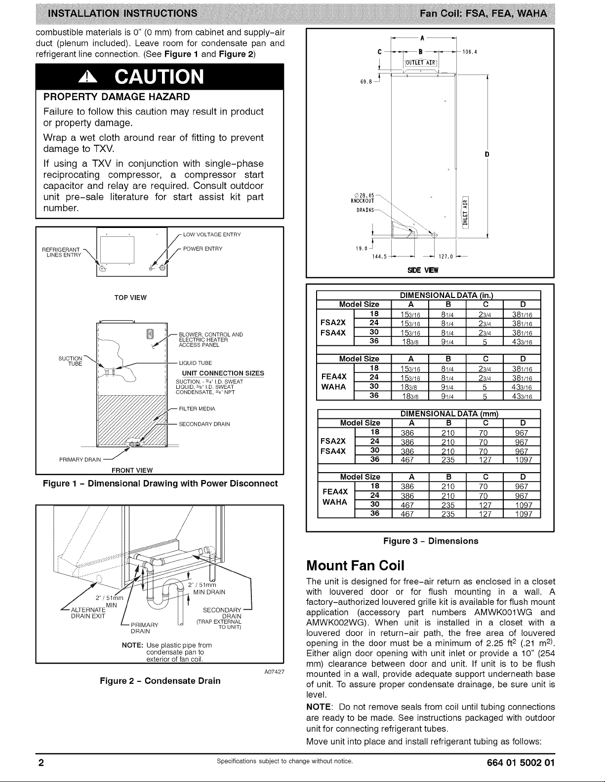
combustible materials is 0" (0 mm) from cabinet and supply-air
duct (plenum included). Leave room for condensate pan and
refrigerant line connection. (See Figure 1 and Figure 2)
PROPERTY DAMAGE HAZARD
Failure to follow this caution may result in product
or property damage.
Wrap a wet cloth around rear of fitting to prevent
damage to TXV.
If using a TXV in conjunction with single-phase
reciprocating compressor, a compressor start
capacitor and relay are required. Consult outdoor
unit pre-sale literature for start assist kit part
number.
REFRIGERANT -X
c B
69.8 _1
_28.45_
KNocKouT_-. _!
DRAINS_ \\\ ,i_.,I
_- \\
106.4
LINES ENTRY Ntk_
TOP VIEW
[_1 BLOWER, CONTROL AND
ACCESS PANEL
II LIQUID TUBE
UNIT CONNECTION SIZES
SUCTION. - 3/4"I.D. SWEAT
LIQUID, 3/d' I.D.SWEAT
CONDENSATE, 3/4"NPT
FILTER MEDIA
-- SECONDARY DRAIN
SUCTION -_,
TUBE
PRIMARY DRAIN j
!
FRONT VIEW
"_1 ELECTRIC HEATER
Figure 1 - Dimensional Drawing with Power Disconnect
SIDEVIEW
Model Size A B C D
DIMENSIONAL DATA (in.)
18 153/16 81/4 23/4 381/16
FSA2X 24 153/16 81/4 23/4 381/16
FSA4X 30 153/16 81/4 23/4 381/16
36 183/8 91/4 5 433/16
Model Size A B C D
FEA4X 24 153/16 81/4 23/4 381/16
WAHA 30 183/8 91/4 5 433/16
18 153/16 81/4 23/4 381/16
36 183/8 91/4 5 433/16
Model Size A B C D
DIMENSIONAL DATA (mm)
18 386 210 70 967
FSA2X 24 386 210 70 967
FSA4X 30 386 210 70 967
36 467 235 127 1097
Model Size A B C D
18 386 210 70 967
FEA4X 24 386 210 70 967
WAHA 30 467 235 127 1097
36 467 235 127 1097
Figure 3 - Dimensions
Mount Fan Coil
MIN DRAIN
MIN
DRAIN EXIT DRAIN
PRIMARY TO UNIT)
DRAIN
NOTE: Use plastic pipe from
condensate pan to
exterior of fan coil.
SECONDARY
(TRAP EXTERNAL
A07427
Figure 2 - Condensate Drain
2 Specifications subject to change without notice. 664 01 5002 01
The unit is designed for free-air return as enclosed in a closet
with Iouvered door or for flush mounting in a wall. A
factory-authorized Iouvered grille kit is available for flush mount
application (accessory part numbers AMWKOOlWG and
AMWK002WG). When unit is installed in a closet with a
Iouvered door in return-air path, the free area of Iouvered
opening in the door must be a minimum of 2.25 ft 2 (.21 m2).
Either align door opening with unit inlet or provide a 10" (254
mm) clearance between door and unit. If unit is to be flush
mounted in a wall, provide adequate support underneath base
of unit. To assure proper condensate drainage, be sure unit is
level.
NOTE: Do not remove seals from coil until tubing connections
are ready to be made. See instructions packaged with outdoor
unit for connecting refrigerant tubes.
Move unit into place and install refrigerant tubing as follows:
Page 3
1.Routetubingtoconnectionpoints.
2.Removeplugsfromliquidandsuctiontubes.
3.Brazeconnectionsusingeithersilverbearingor
non-silverbearingbrazingmaterial.Donotusesoft
solder(materialswhichmeltbelow800°F/ 427°0).
Consult local code requirements.
4. Pressurize system and leak-test. Repeat procedure until
leak-free.
ENVIRONMENTAL HAZARD
Failure to follow this caution may result in
environmental damage,
Do not vent refrigerant to atmosphere, Recover
during system repair or final unit disposal.
Ductwork Specifications
Connect supply-air duct over 3/4" (19 mm) flange provided on
supply-air opening. Secure duct to flange using applicable
fasteners for type of duct used, and seal duct-to-unit joint.
NOTE: Short duct runs tend to increase noise level.
When fan coil is equipped with an electric heater, install air
ducts in accordance with standards 90A and 90B of National
Fire Protection Association (NFPA). Use of flexible connectors
between ductwork and unit will prevent transmission of
vibration. When electric heater is installed, use heat-resistant
material for a flexible connector between ductwork and unit air
discharge connection. Ductwork passing through
unconditioned space must be insulated and covered with a
vapor barrier.
NOTE: Unit is intended for nonducted return-air applications.
Local codes may limit this unit to single-level applications.
Condensate Drain
Condensate pan has primary and secondary drain connections
to meet FHA requirements. (See Figure 2) These connections
have 3/4" (19 mm) female pipe threads. Tubing for all
condensate drains should be a minimum of 7/8" (22 mm) OD.
Drain lines from condensate pan to exterior of unit must be
plastic pipe. Drain should be pitched downward at a slope of 1"
per 10' (25 mm per 3 m). If coil is located in or above a living
space where damage may result from condensate overflow, a
separate 3/4" (19 mm) drain must be provided from secondary
drain connection.
Run this drain to a place in compliance with local installation
codes where it will be noticed when unit is operational.
Condensate flow from secondary drain indicates a plugged
primary drain.
Install a 2" (51 mm) trap in condensate drain line as close to
coil as possible. Make sure that the top of trap is below
connection to drain pan to prevent condensate from
overflowing drain pan. Prime trap with water. Insulate trap if
located above a living area and test condensate line for leaks.
Consult local codes for additional restrictions or precautions.
Field Installation of Controls
Units shipped from factory without controls require a
field-installed cooling control kit or heater. These kits are
completely assembled and factory-wired for easy installation.
See Installation Instructions packaged with control panel for
installation procedures. These unit Installation Instructions are
to be used in conjunction with instructions packaged with
heater or cooling control. When installing accessory heat,
optional cooling control kit is not required.
Electrical Connections
ELECTRICAL OPERATION HAZARD
Failure to follow this warning could result in
personal injury or death.
Before installing or servicing unit, always turn off
all power to unit. There may be more than 1
disconnect switch. Turn off accessory heater
power if applicable. Lock out and tag switch with a
suitable warning label.
NOTE: Before proceeding with electrical connections, make
certain that voltage, frequency, and phase correspond to that
specified on rating plate. Also, check to be sure that the service
provided by utility is sufficient to handle additional load imposed
by this equipment.
Refer to unit wiring label for proper field high- and low-voltage
wiring. Make all electrical connections in accordance with NEC
and any local codes or ordinances that might apply. Unit must
have a separate branch electrical circuit. When equipped with
factory- or field-installed control kit, the fan coil has a
factory-installed disconnect switch located within sight and
readily accessible to the unit.
ELECTRICAL SHOCK HAZARD
Failure to follow this warning could result in
personal injury or death.
Field wires on side of disconnect found in fan coil
remain live, even when pull-out is removed.
Service and maintenance to incoming wiring
cannot be performed until main disconnect switch
(remote to the unit) is turned off. Lock out and tag
switch with a suitable warning label.
Unit cabinet must have a continuous electrical
path to ground in order to minimize potential for
personal injury or death if an electrical fault should
occur. This ground may consist of electrical wire
or approved conduit when installed in accordance
with existing codes.
NOTE: All control kits are shipped from factory wired for
230VAC transformer operation. For 208VAC operation, move
black primary lead from 230VAC terminal to 208VAC terminal.
See Fig. 3 and 4 for field low-voltage wiring. See Fig. 1 for
location of the electrical inlets. For maximum ampacity and
over-current protection, see unit rating plate.
1. Provide power supply for unit being installed in
accordance with unit wiring diagram and rating plate.
2. Connect line-voltage leads to field lugs. Use copper wire
only.
3. Use UL listed conduit and conduit connector for
connecting line-voltage leads to unit and obtaining
proper ground. If conduit connection uses reducing
washers, a separate ground wire must be used.
Grounding can also be accomplished by using the
ground lug provided in the control box.
4. Install rubber grommet packed with unit in hole for
low-voltage wires.
664 01 5002 01 Specifications subject to change without notice. 3
Page 4

5. Connect low-voltage leads to thermostat and outdoor
unit. See Figure 4 and Figure 5 and the outdoor unit
wiring label.
RED
GRY
VlO
FAN COIL
(CONTROL)
R
G
W2
C AIR COND.
THERMOSTAT
--
A98330
Figure 4 - Wiring Layout Air Conditioning Unit
(Cooling and 1-Stage Heat)
THERMOSTAT (CONTROL)
FAN COIL
HEAT PUMP
(CONTROL)
4q= R
z;q_ C
minimum) wire to make low-voltage connections between
thermostat and unit. If thermostat is located more than 100 ft.
(30m) from unit as measured along low-voltage wire, use No.
16 AWG color-coded, insulated (35°C minimum) wire.
Model FSA
All control kits from the factory utilize a printed-circuit board
(PCB) which has a low voltage circuit protective fuse (5 amp.),
fan motor speed tap selection terminal (SPT), and time delay
relay(TDR) jumper. To disable the TDR feature, sever the
jumper wire JWl. (TDR) jumper.
Model FEA and WAHA
There is a 90 second time delay off that cannot be disabled.
Select Proper Blower Speed
Model FSA
Before operating unit, be sure that proper blower speed has
been selected. High speed tap is recommended for most
applications. For those applications requiring lower air flows,
low speed tap can be used.
Fan speeds are selected manually. To change the fan speed,
interchange the black and red fan motor leads on printed circuit
board terminal SPT (COM).
Model FEA and WAHA
Fan speeds are selected at the motor terminal block. To
change motor speeds, disconnect fan lead from terminal 2 and
move to desired tap; Low (1), Medium (2), High (3), and 0.50:
static (5). With a call for thermostat W signal, the motor speed
tap (4) wilt deliver the minimum airflow required for electric heat.
START-UP
Refer to outdoor unit Installation Instructions for system
Fq
Fq
VIO W2
t_ w2
fiq-o
Y
A9833t
Figure 5 - Wiring Layout Heat Pump Unit
(Cooling and 2-Stage Heat)
Refer to unit wiring instructions for recommended wiring
procedures. Use No. 18 AWG color-coded, insulated (35°C
Table 1 -Airflow Performance (Model FSA)
FSA
UNIT SIZE
18
24
30
36
- Airflow outside 450 cfm/ton.
NOTES:
1. Airflow based upon dry coil at 230v with factory approved filter and electric heater (2 element heater sizes 018 through 036). Airflow at 208 volts is approximately
10% lower.
2. Not recommended for use above 0.60 in. wc external static pressure.
BLOWER
SPEED
High
Low
High
Low
High
Low
High
Low
0.10 0.20 0.30 0.40 0.50
732
1128
1053
'40_:
1191
start-up instructions and refrigerant charging method details.
CARE AND MAINTENANCE
For continuing high performance and to minimize possible
equipment failure, it is essential that periodic maintenance be
performed on this equipment. Consult your local dealer as to
proper frequency of maintenance and availability of a
maintenance contract.
The ability to properly perform maintenance on this equipment
requires certain mechanical skills and tools. If you do not
possess these, contact your dealer for maintenance. The only
consumer service recommended or required is filter
maintenance.
EXTERNAL STATIC PRESSURE (in. wc)
CFM
9O8
699
1082
1011
1355
1157
678
861
662
1030
964
1295
1113
641 600
810 754
621 576
973 911
911 854
1227 1152
1061 1000
0.60
693
527
845
791
1068
931
4 Specifications subject to change without notice. 664 01 5002 01
Page 5

Table 2 - Airflow Performance (Model FEA and WAHA)
FEAandWAHA
UNITSIZE
Blower Speed
Tap5
Tap4
18
Tap3
Tap2
Tap 1
Tap5
Tap4
24
Tap3
Tap2
Tap 1
Tap5
Tap4
30
Tap3
Tap2
Tap 1
Tap5
Tap4
36
Tap3
Tap2
Tap 1
- Airflow outside 450cfm/ton.
NOTES:
1. Airflow based upon dry coil at 230v with factory approved filter and electric heater (2 element heater sizes 18 through 36).
2. Airflow at 208 volts is approximately the same as 230 volts because the X13 motor is a constant torque motor. The torque doesn't drop off at the speeds
the motor operates.
3. Not recommended for use above 0.60 in. external static pressure.
Table 3 - Air Delivery Performance Correction Component Pressure Drop (in. wc) at Indicated Airflow (Dry-To-Wet Coil)
FSA CFM
UNIT SIZE 500 600 700 800 900 1000 1100 1200 1300
18 0.034 0.049 0.063 ............
24 0.021 0.033 0.045 0.056 0.068 ........
30 ...... 0.056 0.068 0.079 0.090 ....
36 .......... 0.055 0.064 0.073 0.081
FEA
and CFM
WAHA
UNIT SIZE 500 600 700 800 900 1000 1100 1200 1300
18 0.034 0.049 0.063 ............
24 0.021 0.033 0.045 0.056 0.068 ........
30 ...... 0.056 0.068 0.079 0.090 ....
36 .......... 0.055 0.064 0.073 0.081
0.10 0.20
611
660
611
554
736
83O
736
616
1110
1025
1025
904
724
1217
1072
908
731
568
618
568
509
888
707
804
707
568
1085
988
988
864
684
1321
1190
1041
877
670
0.30
668
539
584
539
463
866
653
768
653
532
1049
960
960
839
631
1282
1157
1007
828
612
0.40
630
496
547
496
418
832
611
734
611
484
1022
924
924
797
581
1245
1128
968
776
576
0,50
6O2
451
5O5
451
388
797
579
699
579
429
991
894
894
762
546
1195
1093
920
741
524
0.60
564
42O
468
42O
348
764
528
647
528
378
958
85O
850
716
500
1135
1054
886
694
488
Table 4 - Air Delivery Performance Correction Component Pressure Drop (in. wc) at Indicated Airflow
AIR DELIVERY (CFM) 400 500 600 700 800 900 1000 1100
Electric 1-Element 5 kW 0.007 0.010 0.015 0.025 0.035 0.055 0.070 0.080
Heaters 2-Element 7.5 & 11 kW 0.010 0.012 0.018 0.028 0.050 0.075 0.100 0.130
Subtractthe above pressure dropcorrections from unit airflow data when that component or condition is used.The remaining externalstatic pressurewill be availablefor
the duct system.
International Comfort Product, LLC • PO Box 128 •
Lewisburg, TN 37091 USA
664 01 5002 01 Specifications subject to change without notice. 5
Page 6

NOTE: Read the entire instruction manual before starting
installation.
TABLE OF CONTENTS
PAGE
SAFETY CONSIDERATIONS ........................... 1
INTRODUCTION ...................................... 1
INSTALLATION ....................................... 1
CHECK EQUIPMENT .................................. 1
MOUNT FAN COIL .................................... 2
DUCTWORK SPECIFICATIONS ......................... 3
CONDENSATE DRAIN ................................. 3
FIELD INSTALLATION OF CONTROLS .................. 3
ELECTRICAL CONNECTIONS .......................... 3
SELECT PROPER BLOWER SPEED .................... 4
START-UP ........................................... 4
CARE AND MAINTENANCE ............................ 4
AIRFLOW PERFORMANCE ............................ 4
SAFETY CONSIDERATIONS
Improper installation, adjustment, alteration, service,
maintenance, or use can cause explosion, fire, electrical shock,
or other conditions which may cause death, personal injury or
property damage. Consult a qualified installer, service agency,
or your distributor or branch for information or assistance. The
qualified installer or agency must use factory-authorized kits or
accessories when modifying this product. Refer to individual
instructions packaged with kits or accessories when installing.
Follow all safety codes. Wear safety glasses, protective
clothing, and work gloves. Use quenching cloth for brazing
operations. Have a fire extinguisher available. Read these
instructions thoroughly and follow all warning or cautions
included in literature and attached to the unit. Consult local
building codes and the current editions of the National
Electrical Code (NEC) NFPA 70.
In Canada, refer to the current editions of Canadian Electrical
Code CSA C22.1.
Recognize safety information. This is the safety alert symbol
/K. When you see this symbol on the unit and in instructions
or manuals, be alert to the potential for personal injury.
Understand the signal words DANGER, WARNING, and
CAUTION. These words are used with the safety alert symbol.
DANGER identifies the most serious hazards which will result
in severe personal injury or death. WARNING signifies hazards
which could result in personal injury or death. CAUTION is
used to identify unsafe practices, which may result in minor
personal injury or product and property damage. NOTE is used
to highlight suggestions which will result in enhanced
installation, reliability, or operation.
INTRODUCTION
Fan Coils may be used for cooling or heat pump operation, with or
without electric heat. Models are available with factory installed
electric heaters (5 kW, 7.5 kW, or 11 kw) and with no heat.
Installations without electric heat require a Cooling Control Kit
(accessory part number AMWK001CK).
FEA and WAHA Fan Coils may be used for cooling or heat pump
operation, with or without electric heat. Models have factory installed
electric heaters (5 kW, 7.5 kW, or 11 kw).
FSA, FEA, and WAHA Fan Coils are designed to be installed in an
upflow position, free air return ONLY, suitable for closet or
flush-mount installations.
Units are designed for upflow applications only. Local codes
may limit this free-air-return type unit to installation in
single-level applications. When electric heater is not needed, a
factory approved accessory cooling control package is
required. See instructions packaged with accessory for
installation procedures.
ELECTRICAL OPERATION HAZARD
Failure to follow this warning could result in
personal injury or death.
Before installing or servicing unit, always turn off
all power to unit. There may be more than 1
disconnect switch. Turn off accessory heater
power if applicable. Lock out and tag switch with a
suitable warning label.
CUT HAZARD
Failure to follow this caution may result in personal
injury.
Sheet metal parts may have sharp edges or burrs.
Use care and wear appropriate protective clothing
and gloves when handling parts.
INSTALLATION
Check Equipment
Unpack unit and move to final location. Remove carton, taking
care not to damage unit. Inspect equipment for damage prior to
installation. File claim with shipping company if shipment is
damaged or incomplete. Locate rating plate on unit. It contains
information needed to properly install unit. Check rating plate to
be sure unit matches job specifications. A front access panel is
provided, which permits access to blower assembly and
electrical controls for removal and servicing.
NOTE: Minimum clearance of 21" (533 mm) is required in front
of access panel for servicing only. Installation clearance from
Specificationssubjectto change without notice. 664 01 5002 01 Dec. 2012
Page 7

combustible materials is 0" (0 mm) from cabinet and supply-air
duct (plenum included). Leave room for condensate pan and
refrigerant line connection. (See Figure 1 and Figure 2)
PROPERTY DAMAGE HAZARD
Failure to follow this caution may result in product
or property damage.
Wrap a wet cloth around rear of fitting to prevent
damage to TXV.
If using a TXV in conjunction with single-phase
reciprocating compressor, a compressor start
capacitor and relay are required. Consult outdoor
unit pre-sale literature for start assist kit part
number.
REFRIGERANT -X
c B
69.8 _1
_28.45_
KNocKouT_-. _!
DRAINS_ \\\ ,i_.,I
_- \\
106.4
LINES ENTRY Ntk_
TOP VIEW
[_1 BLOWER, CONTROL AND
ACCESS PANEL
II LIQUID TUBE
UNIT CONNECTION SIZES
SUCTION. - 3/4"I.D. SWEAT
LIQUID, 3/d' I.D. SWEAT
CONDENSATE, 3/4"NPT
FILTER MEDIA
-- SECONDARY DRAIN
SUCTION -_,
TUBE
PRIMARY DRAIN j
!
FRONT VIEW
"_1 ELECTRIC HEATER
Figure 1 - Dimensional Drawing with Power Disconnect
SIDEVIEW
Model Size A B C D
DIMENSIONAL DATA (in.)
18 153/16 81/4 23/4 381/16
FSA2X 24 153/16 81/4 23/4 381/16
FSA4X 30 153/16 81/4 23/4 381/16
36 183/8 91/4 5 433/16
Model Size A B C D
FEA4X 24 153/16 81/4 23/4 381/16
WAHA 30 183/8 91/4 5 433/16
18 153/16 81/4 23/4 381/16
36 183/8 91/4 5 433/16
Model Size A B C D
DIMENSIONAL DATA (mm)
18 386 210 70 967
FSA2X 24 386 210 70 967
FSA4X 30 386 210 70 967
36 467 235 127 1097
Model Size A B C D
18 386 210 70 967
FEA4X 24 386 210 70 967
WAHA 30 467 235 127 1097
36 467 235 127 1097
Figure 3 - Dimensions
Mount Fan Coil
MIN DRAIN
MIN
DRAIN EXIT DRAIN
PRIMARY TO UNIT)
DRAIN
NOTE: Use plastic pipe from
condensate pan to
exterior of fan coil.
SECONDARY
(TRAP EXTERNAL
A07427
Figure 2 - Condensate Drain
2 Specifications subject to change without notice. 664 01 5002 01
The unit is designed for free-air return as enclosed in a closet
with Iouvered door or for flush mounting in a wall. A
factory-authorized Iouvered grille kit is available for flush mount
application (accessory part numbers AMWKOOlWG and
AMWK002WG). When unit is installed in a closet with a
Iouvered door in return-air path, the free area of Iouvered
opening in the door must be a minimum of 2.25 ft 2 (.21 m2).
Either align door opening with unit inlet or provide a 10" (254
mm) clearance between door and unit. If unit is to be flush
mounted in a wall, provide adequate support underneath base
of unit. To assure proper condensate drainage, be sure unit is
level.
NOTE: Do not remove seals from coil until tubing connections
are ready to be made. See instructions packaged with outdoor
unit for connecting refrigerant tubes.
Move unit into place and install refrigerant tubing as follows:
Page 8

1.Routetubingtoconnectionpoints.
2.Removeplugsfromliquidandsuctiontubes.
3.Brazeconnectionsusingeithersilverbearingor
non-silverbearingbrazingmaterial.Donotusesoft
solder(materialswhichmeltbelow800°F/ 427°0).
Consult local code requirements.
4. Pressurize system and leak-test. Repeat procedure until
leak-free.
ENVIRONMENTAL HAZARD
Failure to follow this caution may result in
environmental damage,
Do not vent refrigerant to atmosphere, Recover
during system repair or final unit disposal.
Ductwork Specifications
Connect supply-air duct over 3/4" (19 mm) flange provided on
supply-air opening. Secure duct to flange using applicable
fasteners for type of duct used, and seal duct-to-unit joint.
NOTE: Short duct runs tend to increase noise level.
When fan coil is equipped with an electric heater, install air
ducts in accordance with standards 90A and 90B of National
Fire Protection Association (NFPA). Use of flexible connectors
between ductwork and unit will prevent transmission of
vibration. When electric heater is installed, use heat-resistant
material for a flexible connector between ductwork and unit air
discharge connection. Ductwork passing through
unconditioned space must be insulated and covered with a
vapor barrier.
NOTE: Unit is intended for nonducted return-air applications.
Local codes may limit this unit to single-level applications.
Condensate Drain
Condensate pan has primary and secondary drain connections
to meet FHA requirements. (See Figure 2) These connections
have 3/4" (19 mm) female pipe threads. Tubing for all
condensate drains should be a minimum of 7/8" (22 mm) OD.
Drain lines from condensate pan to exterior of unit must be
plastic pipe. Drain should be pitched downward at a slope of 1"
per 10' (25 mm per 3 m). If coil is located in or above a living
space where damage may result from condensate overflow, a
separate 3/4" (19 mm) drain must be provided from secondary
drain connection.
Run this drain to a place in compliance with local installation
codes where it will be noticed when unit is operational.
Condensate flow from secondary drain indicates a plugged
primary drain.
Install a 2" (51 mm) trap in condensate drain line as close to
coil as possible. Make sure that the top of trap is below
connection to drain pan to prevent condensate from
overflowing drain pan. Prime trap with water. Insulate trap if
located above a living area and test condensate line for leaks.
Consult local codes for additional restrictions or precautions.
Field Installation of Controls
Units shipped from factory without controls require a
field-installed cooling control kit or heater. These kits are
completely assembled and factory-wired for easy installation.
See Installation Instructions packaged with control panel for
installation procedures. These unit Installation Instructions are
to be used in conjunction with instructions packaged with
heater or cooling control. When installing accessory heat,
optional cooling control kit is not required.
Electrical Connections
ELECTRICAL OPERATION HAZARD
Failure to follow this warning could result in
personal injury or death.
Before installing or servicing unit, always turn off
all power to unit. There may be more than 1
disconnect switch. Turn off accessory heater
power if applicable. Lock out and tag switch with a
suitable warning label.
NOTE: Before proceeding with electrical connections, make
certain that voltage, frequency, and phase correspond to that
specified on rating plate. Also, check to be sure that the service
provided by utility is sufficient to handle additional load imposed
by this equipment.
Refer to unit wiring label for proper field high- and low-voltage
wiring. Make all electrical connections in accordance with NEC
and any local codes or ordinances that might apply. Unit must
have a separate branch electrical circuit. When equipped with
factory- or field-installed control kit, the fan coil has a
factory-installed disconnect switch located within sight and
readily accessible to the unit.
ELECTRICAL SHOCK HAZARD
Failure to follow this warning could result in
personal injury or death.
Field wires on side of disconnect found in fan coil
remain live, even when pull-out is removed.
Service and maintenance to incoming wiring
cannot be performed until main disconnect switch
(remote to the unit) is turned off. Lock out and tag
switch with a suitable warning label.
Unit cabinet must have a continuous electrical
path to ground in order to minimize potential for
personal injury or death if an electrical fault should
occur. This ground may consist of electrical wire
or approved conduit when installed in accordance
with existing codes.
NOTE: All control kits are shipped from factory wired for
230VAC transformer operation. For 208VAC operation, move
black primary lead from 230VAC terminal to 208VAC terminal.
See Fig. 3 and 4 for field low-voltage wiring. See Fig. 1 for
location of the electrical inlets. For maximum ampacity and
over-current protection, see unit rating plate.
1. Provide power supply for unit being installed in
accordance with unit wiring diagram and rating plate.
2. Connect line-voltage leads to field lugs. Use copper wire
only.
3. Use UL listed conduit and conduit connector for
connecting line-voltage leads to unit and obtaining
proper ground. If conduit connection uses reducing
washers, a separate ground wire must be used.
Grounding can also be accomplished by using the
ground lug provided in the control box.
4. Install rubber grommet packed with unit in hole for
low-voltage wires.
664 01 5002 01 Specifications subject to change without notice. 3
Page 9

5. Connect low-voltage leads to thermostat and outdoor
unit. See Figure 4 and Figure 5 and the outdoor unit
wiring label.
RED
GRY
VlO
FAN COIL
(CONTROL)
R
G
W2
C AIR COND.
THERMOSTAT
--
A98330
Figure 4 - Wiring Layout Air Conditioning Unit
(Cooling and 1-Stage Heat)
THERMOSTAT (CONTROL)
FAN COIL
HEAT PUMP
(CONTROL)
4q= R
z;q_ C
minimum) wire to make low-voltage connections between
thermostat and unit. If thermostat is located more than 100 ft.
(30m) from unit as measured along low-voltage wire, use No.
16 AWG color-coded, insulated (35°C minimum) wire.
Model FSA
All control kits from the factory utilize a printed-circuit board
(PCB) which has a low voltage circuit protective fuse (5 amp.),
fan motor speed tap selection terminal (SPT), and time delay
relay(TDR) jumper. To disable the TDR feature, sever the
jumper wire JWl. (TDR) jumper.
Model FEA and WAHA
There is a 90 second time delay off that cannot be disabled.
Select Proper Blower Speed
Model FSA
Before operating unit, be sure that proper blower speed has
been selected. High speed tap is recommended for most
applications. For those applications requiring lower air flows,
low speed tap can be used.
Fan speeds are selected manually. To change the fan speed,
interchange the black and red fan motor leads on printed circuit
board terminal SPT (COM).
Model FEA and WAHA
Fan speeds are selected at the motor terminal block. To
change motor speeds, disconnect fan lead from terminal 2 and
move to desired tap; Low (1), Medium (2), High (3), and 0.50:
static (5). With a call for thermostat W signal, the motor speed
tap (4) wilt deliver the minimum airflow required for electric heat.
START-UP
Refer to outdoor unit Installation Instructions for system
Fq
Fq
VIO W2
t_ w2
fiq-o
Y
A9833t
Figure 5 - Wiring Layout Heat Pump Unit
(Cooling and 2-Stage Heat)
Refer to unit wiring instructions for recommended wiring
procedures. Use No. 18 AWG color-coded, insulated (35°C
Table 1 -Airflow Performance (Model FSA)
FSA
UNIT SIZE
18
24
30
36
- Airflow outside 450 cfm/ton.
NOTES:
1. Airflow based upon dry coil at 230v with factory approved filter and electric heater (2 element heater sizes 018 through 036). Airflow at 208 volts is approximately
10% lower.
2. Not recommended for use above 0.60 in. wc external static pressure.
BLOWER
SPEED
High
Low
High
Low
High
Low
High
Low
0.10 0.20 0.30 0.40 0.50
732
1128
1053
'40_:
1191
start-up instructions and refrigerant charging method details.
CARE AND MAINTENANCE
For continuing high performance and to minimize possible
equipment failure, it is essential that periodic maintenance be
performed on this equipment. Consult your local dealer as to
proper frequency of maintenance and availability of a
maintenance contract.
The ability to properly perform maintenance on this equipment
requires certain mechanical skills and tools. If you do not
possess these, contact your dealer for maintenance. The only
consumer service recommended or required is filter
maintenance.
EXTERNAL STATIC PRESSURE (in. wc)
CFM
9O8
699
1082
1011
1355
1157
678
861
662
1030
964
1295
1113
641 600
810 754
621 576
973 911
911 854
1227 1152
1061 1000
0.60
693
527
845
791
1068
931
4 Specifications subject to change without notice. 664 01 5002 01
Page 10

Table 2 - Airflow Performance (Model FEA and WAHA)
FEAandWAHA
UNITSIZE
Blower Speed
Tap5
Tap4
18
Tap3
Tap2
Tap 1
Tap5
Tap4
24
Tap3
Tap2
Tap 1
Tap5
Tap4
30
Tap3
Tap2
Tap 1
Tap5
Tap4
36
Tap3
Tap2
Tap 1
- Airflow outside 450cfm/ton.
NOTES:
1. Airflow based upon dry coil at 230v with factory approved filter and electric heater (2 element heater sizes 18 through 36).
2. Airflow at 208 volts is approximately the same as 230 volts because the X13 motor is a constant torque motor. The torque doesn't drop off at the speeds
the motor operates.
3. Not recommended for use above 0.60 in. external static pressure.
Table 3 - Air Delivery Performance Correction Component Pressure Drop (in. wc) at Indicated Airflow (Dry-To-Wet Coil)
FSA CFM
UNIT SIZE 500 600 700 800 900 1000 1100 1200 1300
18 0.034 0.049 0.063 ............
24 0.021 0.033 0.045 0.056 0.068 ........
30 ...... 0.056 0.068 0.079 0.090 ....
36 .......... 0.055 0.064 0.073 0.081
FEA
and CFM
WAHA
UNIT SIZE 500 600 700 800 900 1000 1100 1200 1300
18 0.034 0.049 0.063 ............
24 0.021 0.033 0.045 0.056 0.068 ........
30 ...... 0.056 0.068 0.079 0.090 ....
36 .......... 0.055 0.064 0.073 0.081
0.10 0.20
611
660
611
554
736
83O
736
616
1110
1025
1025
904
724
1217
1072
908
731
568
618
568
509
888
707
804
707
568
1085
988
988
864
684
1321
1190
1041
877
670
0.30
668
539
584
539
463
866
653
768
653
532
1049
960
960
839
631
1282
1157
1007
828
612
0.40
630
496
547
496
418
832
611
734
611
484
1022
924
924
797
581
1245
1128
968
776
576
0,50
6O2
451
5O5
451
388
797
579
699
579
429
991
894
894
762
546
1195
1093
920
741
524
0.60
564
42O
468
42O
348
764
528
647
528
378
958
85O
850
716
500
1135
1054
886
694
488
Table 4 - Air Delivery Performance Correction Component Pressure Drop (in. wc) at Indicated Airflow
AIR DELIVERY (CFM) 400 500 600 700 800 900 1000 1100
Electric 1-Element 5 kW 0.007 0.010 0.015 0.025 0.035 0.055 0.070 0.080
Heaters 2-Element 7.5 & 11 kW 0.010 0.012 0.018 0.028 0.050 0.075 0.100 0.130
Subtractthe above pressure dropcorrections from unit airflow datawhen that componentor condition is used.The remainingexternal static pressurewill be available for
the duct system.
International Comfort Product, LLC • PO Box 128 •
Lewisburg, TN 37091 USA
664 01 5002 01 Specifications subject to change without notice. 5
 Loading...