

Page 1
These instructions must be read and understood completely before attempting installation.
Safety Labeling and Signal Words
DANGER, WARNING, CAUTION, and
NOTE
The signal words DANGER, WARNING,
CAUTION, and NOTE are used to identify levels of
hazard seriousness. The signal word DANGER is
only used on product labels to signify an immediate
hazard. The signal words WARNING, CAUTION,
and NOTE will be used on product labels and
throughout this manual and other manuals that may
apply to the product.
DANGER - Immediate hazards which will result in
severe personal injury or death.
WARNING - Hazards or unsafe practices which
could result in severe personal injury or death.
CAUTION - Hazards or unsafe practices which
may result in minor personal injury or product or
property damage.
NOTE - Used to highlight suggestions which will
result in enhanced installation, reliability, or
operation.
Signal Words in Manuals
The signal word WARNING is used throughout this
manual in the following manner:
The signal word CAUTION is used throughout this
manual in the following manner:
Signal Words on Product Labeling
Signal words are used in combination with colors
and/or pictures on product labels.
TABLE OF CONTENTS
Introduction .................................... 2
Check Equipment .............................. 2
Location ....................................... 2
Installation .................................. 2 - 6
Electrical Connections ....................... 6 - 7
Controls - FSA ................................ 7
Motor Speed Selection .......................... 8
Start-up Procedures ............................ 8
Care and Maintenance .......................... 8
DEATH, PERSONAL INJURY, AND/OR PROPERTY
DAMAGE HAZARD
Failure to carefully read and follow this warning
could result in equipment malfunction, property
damage, personal injury and/or death.
Installation or repairs made by unqualified per-
sons could result in equipment malfunction, prop-
erty damage, personal injury and/or death.
The information contained in this manual is in-
tended for use by a qualified service technician fa-
miliar with safety procedures and equipped with
the proper tools and test instruments.
Installation must conform with local building
codes and with the National Electrical Code
NFPA70 current edition.
66401500200 Feb2009
Page 2
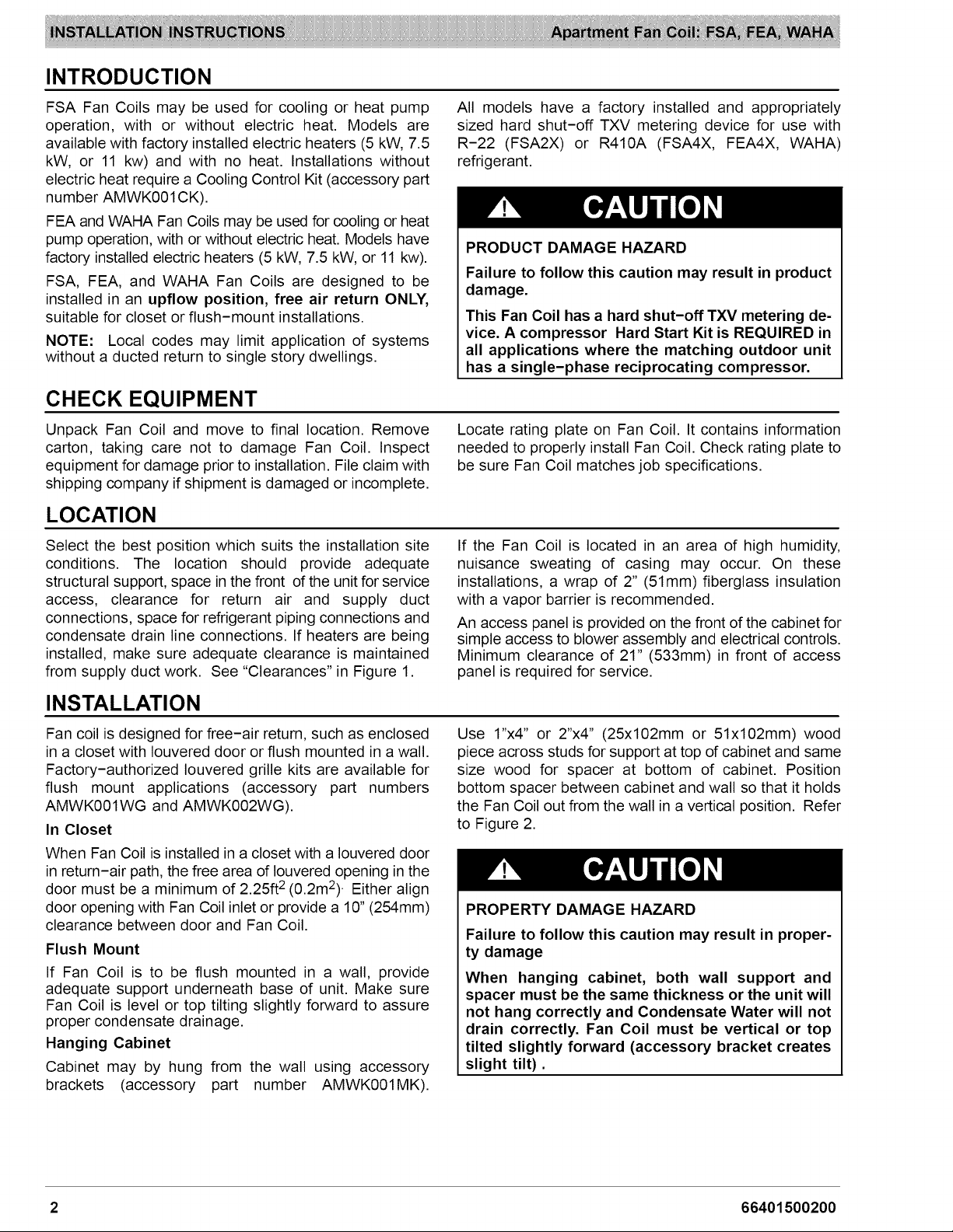
INTRODUCTION
FSA Fan Coils may be used for cooling or heat pump
operation, with or without electric heat. Models are
available with factory installed electric heaters (5 kW, 7.5
kW, or 11 kw) and with no heat. Installations without
electric heat require a Cooling Control Kit (accessory part
number AMWK001CK).
FEA and WAHA Fan Coils may be used for cooling or heat
pump operation, with or without electric heat. Models have
factory installed electric heaters (5 kW, 7.5 kW, or 11 kw).
FSA, FEA, and WAHA Fan Coils are designed to be
installed in an upflow position, free air return ONLY,
suitable for closet or flush-mount installations.
NOTE: Local codes may limit application of systems
without a ducted return to single story dwellings.
CHECK EQUIPMENT
Unpack Fan Coil and move to final location. Remove
carton, taking care not to damage Fan Coil. Inspect
equipment for damage prior to installation. File claim with
shipping company if shipment is damaged or incomplete.
LOCATION
Select the best position which suits the installation site
conditions. The location should provide adequate
structural support, space in the front of the unit for service
access, clearance for return air and supply duct
connections, space for refrigerant piping connections and
condensate drain line connections. If heaters are being
installed, make sure adequate clearance is maintained
from supply duct work. See "Clearances" in Figure 1.
All models have a factory installed and appropriately
sized hard shut-off TXV metering device for use with
R-22 (FSA2X) or R410A (FSA4X, FEA4X, WAHA)
refrigerant.
PRODUCT DAMAGE HAZARD
Failure to follow this caution may result in product
damage.
This Fan Coil has a hard shut-off TXV metering de-
vice. A compressor Hard Start Kit is REQUIRED in
all applications where the matching outdoor unit
has a single-phase reciprocating compressor.
Locate rating plate on Fan Coil. It contains information
needed to properly install Fan Coil. Check rating plate to
be sure Fan Coil matches job specifications.
If the Fan Coil is located in an area of high humidity,
nuisance sweating of casing may occur. On these
installations, a wrap of 2" (51mm) fiberglass insulation
with a vapor barrier is recommended.
An access panel is provided on the front of the cabinet for
simple access to blower assembly and electrical controls.
Minimum clearance of 21" (533mm) in front of access
panel is required for service.
INSTALLATION
Fan coil is designed for free-air return, such as enclosed
in a closet with Iouvered door or flush mounted in a wall.
Factory-authorized Iouvered grille kits are available for
flush mount applications (accessory part numbers
AMWK001WG and AMWK002WG).
In Closet
When Fan Coil is installed in a closet with a Iouvered door
in return-air path, the free area of Iouvered opening in the
door must be a minimum of 2.25ft 2 (0.2m2)• Either align
door opening with Fan Coil inlet or provide a 10" (254mm)
clearance between door and Fan Coil.
Flush Mount
If Fan Coil is to be flush mounted in a wall, provide
adequate support underneath base of unit. Make sure
Fan Coil is level or top tilting slightly forward to assure
proper condensate drainage.
Hanging Cabinet
Cabinet may by hung from the wall using accessory
brackets (accessory part number AMWK001MK).
Use 1"x4" or 2"x4" (25x102mm or 51x102mm) wood
piece across studs for support at top of cabinet and same
size wood for spacer at bottom of cabinet. Position
bottom spacer between cabinet and wall so that it holds
the Fan Coil out from the wall in a vertical position. Refer
to Figure 2.
PROPERTY DAMAGE HAZARD
Failure to follow this caution may result in proper-
ty damage
When hanging cabinet, both wall support and
spacer must be the same thickness or the unit will
not hang correctly and Condensate Water will not
drain correctly. Fan Coil must be vertical or top
tilted slightly forward (accessory bracket creates
slight tilt).
2 66401500200
Page 3
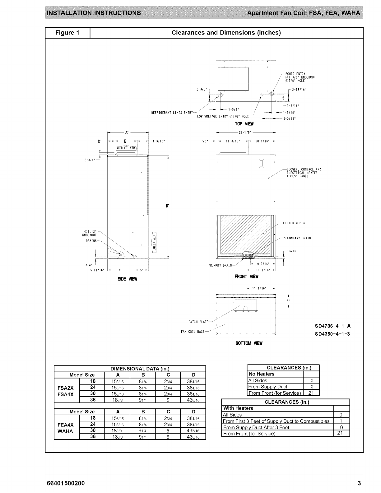
Figure1 [ ClearancesandDimensions(inches)
// _7/8" HOLE
REFRIGERANT LINES ENTRY LOW VOLTAGE EN _ 8" OLE ' _.. .
TOP VIEW
C" B" _4-3/16" 7/8"_ _11-3/16° _t0-t/t6 °_
2"314" _ ff
D"
rPOWER ENTRY
_t 318" KNOCKOUT
LOWER, CONTROL AND
LECTRICAL HEATER
ACCESS PANEL
_1.I2"
KNOCKOUT \.
DRAINS _
3/4" l ......................
5-11/t6"
SIDEVIEW
DIMENSIONAL DATA (in.)
Model Size A B C D
18 153/16 81/4 23/4 381/16
FSA2X 24 153/16 81/4 23/4 381/16
FSA4X 30 153/16 81/4 23/4 381/16
36 183/8 91/4 5 433/16
Model Size A B C D
18 153/16 81/4 23/4 381/16
FEA4X 24 153/16 81/4 23/4 381/16
WAHA 30 183/8 91/4 5 433/16
36 183/8 91/4 5 433/16
.........FILTER MEDIA
_ SECONDARY DRAIN
13116"
PRmARY i 9-7/16......
............ ti-1/16 ....
FRONTV_
11_1/16_ .
BOTTOMVIEW
CLEARANCES (in.)
No Heaters
All Sides 0
From Supply Duct 0
From Front (for Service) 21
CLEARANCES (in.)
With Heaters
All Sides
From First 3 Feet of Supply Duct to Combustibles
From Supply Duct After 3 Feet
From Front (for Service)
SD4786-4-1-A
SD4350-4-1-3
0
1
0
21
66401500200 3
Page 4

Figure 1
(cont) Clearances and Dimensions (mm)
c B
F
69,8 _
R8.45
KNOCKOUT
DRAINS--. _\
:: _ / _34.93 KNOCKOUT
60.3 l _,/ 71,4
/ ; // /:_ 61.9
REFRIGERANT LINES ENTRY / -- _" 41.3 // / "_ ; 39,7
LOW VOLTAGE ENTRY _22,23 HOLE / L- _ t31,8
TOP VIEW
562.0
106,4
2227i _284.2_255.6_
If
_" ACCESS PANEL
/::1
; .........POWER ENTRY
/ _22.23 HOLE
/ BLOWER, CONTROL AND
ELECTRICAL HEATER
t9.1t 1!4.5
_ VIEW
PATCH PLATE _ .-_
FAN COIL BASE--''_
DIMENSIONAL DATA (ram)
Model Size A B C D
18 386 210 70 967
FSA2X 24 386 210 70 967
FSA4X 30 386 210 70 967
36 467 235 127 1097
ModelSize A B C D
18 386 210 70 967
FEA4X 24 386 210 70 967
WAHA 30 467 235 127 1097
36 467 235 127 1097
FRONTVIEW
......................._ ..............._ .........._ ..........................__
: 281.0
BOTTOM VIEW
CLEARANCES (mm)
No Heaters
All Sides 0
From Supply Duct 0
From Front (for Service) 533
CLEARANCES (ram)
With Heaters
All Sides
From First 3 Feet of Supply Duct to Combustibles
From Supply Duct After 3 Feet
From Front (for Service)
SD4786-4-1-A
SD4350-4-1-3
0
25
0
533
4 66401500200
Page 5

Figure2 L
HangingCabinetonWall
Support Brackets
Duct Connections
Connect supply-air duct over 3/4" (19mm) flange
provided on supply-air opening. Secure duct to flange
using applicable fasteners for type of duct used, and seal
duct-to-unit joint.
NOTE: Short duct runs tend to increase noise level.
When fan coil is equipped with an electric heater, install
air ducts in accordance with standards 90A and 90B of
National Fire Protection Association (NFPA). Use of
flexible connectors between ductwork and Fan Coil will
prevent transmission of vibration.
When electric heater is installed, use heat-resistant
material for a flexible connector between ductwork and
Fan Coil air discharge connection.
Ductwork passing through unconditioned space must be
insulated and covered with a vapor barrier.
NOTE: Fan Coil is intended for non-ducted return-air
applications. Local codes may limit this unit to
single-level applications.
FIRE HAZARD
Failure to maintain proper clearances could result
in personal injury, death, and/or property damage.
When heaters are installed, maintain clearances
from combustible materials as specified on unit
rating plate. Do not use plastic lined or combus-
tible flexible ducting within 36 inches (914mm) of
the supply end of the fan coil.
Condensate Drain
Condensate pan has primary and secondary drain
connections to meet FHA requirements (refer to Figure
3). These connections have 3/4" (19mm) female pipe
threads (NPT).
Tubing for all condensate drains should be a minimum of
7/8" OD (22mm). Drain lines from condensate pan to
exterior of unit must be plastic pipe. Drain should be
pitched downward at a slope of 1 inch per 10 feet (25mm
per 3m).
If coil is located in or above a living space where damage
may result from condensate overflow, a separate 3/4"
(19mm) drain must be provided from secondary drain
connection. Run this drain to a place in compliance with
local installation codes where it will be noticed when unit is
operational.
Condensate flowing from secondary drain indicates a
plugged primary drain.
Install a 3" (76mm) trap in condensate drain line as close
to coil as possible. Make sure that the top of trap is below
connection to drain pan to prevent condensate from
overflowing drain pan. Prime trap with water. Insulate
drain if located above a living area and test condensate
line for leaks.
Consult local codes for additional restrictions or
precautions.
Figure 3 _ Condensate Drain
/ /
/ /
/ /
/ /
/ /
/ /
/ _
./
'_ALTERNATE
DRAIN EXIT
/'
/
/
/
............PRIMARY
DRAIN
NOTE: Use plastic pipe from
condensate pan to
exterior of fan coil,
3-tN. MIN TRAP
(.76mm)
SECONDARY DRAIN
(TRAP EXTERNAL TO UNIT)
A86005
66401500200 5
Page 6

RefrigerantLines
NOTE:Do not remove seals from coil until tubing
connections are ready to be made. See instructions
packaged with outdoor unit for connecting refrigerant
tubes.
ELECTRICAL CONNECTIONS
ELECTRICAL SHOCK HAZARD
Failure to turn off the main (remote) disconnect
device before working on incoming (field) wiring
could result in personal injury or death.
Incoming (field) wires on the line side of the dis-
connect found in the fan coil unit remain live, even
when the pull-out is removed. Service and main-
tenance to incoming (field) wiring cannot be safely
performed until the main disconnect switch (re-
mote to the unit) is turned off.
NOTE: Before proceeding with electrical connections,
make certain that voltage, frequency, and phase
correspond to that specified on rating plate. Also, check to
be sure that the service provided by utility is sufficient to
handle additional load imposed by this equipment. Refer
to unit wiring label for proper field high-voltage and
low-voltage wiring.
Make all electrical connections in accordance with NEC
and any local codes or ordinances that might apply.
Fan Coil must have a separate branch electrical circuit.
Heater supply circuit wire size and overcurrent protection
must comply with National Electrical Code (NEC) and UL
branch circuit requirements. Wires and overcurrent
protection, integral to the heater, are not required to meet
branch circuit requirements. Internal circuit protection of
60 amps (maximum)is acceptable.
The Cooling Control Kit (FSA) and the heater packages
provide a disconnect switch located within sight and
readily accessible to the unit.
NOTE: All control kits are shipped from factory wired for
230V transformer operation. When 208V transformer
operation is required, move the black primary lead from
the 230V terminal to the 208V terminal.
Refer to Figure 1 for location of the electrical inlets. Refer
to unit rating plate for minimum circuit ampacity (MCA)
and maximum fuse or circuit breaker (maximum
over-current protection - MOCP).
1. Provide power supply for Fan Coil in accordance
with unit wiring diagram and rating plate.
2. Connect line-voltage leads to field lugs. Use
copper wire only.
Move Fan Coil into place and install refrigerant tubing as
follows:
1. Route tubing to connection points.
2. Remove plugs from liquid and suction tubes.
3. Clean tubing and braze in place.
4. Pressurize system and leak test. Repeat
procedure until leak free.
3. Use UL listed conduit and conduit connector for
connecting line-voltage leads to unit and obtaining
proper ground. Grounding can also be
accomplished by using the ground lug provided in
the control box.
4. Install rubber grommet packed with unit in hole for
low-voltage wires.
5. Connect low-voltage leads to thermostat and
outdoor unit. Refer to Figures 4 and 5 and the
outdoor unit wiring label.
Use No. 18 AWG color-coded, insulated (35 °C
minimum) wire to make low-voltage connections
between thermostat and Fan Coil. If thermostat is located
more than 100 feet (31m)from Fan Coil as measured
along low-voltage wire, use No. 16 AWG color-coded,
insulated (35 °C minimum) wire. For FSA fan coil, all
control kits from the factory utilize a printed-circuit board
(PCB) which has a low voltage circuit protective fuse (5
amp), fan motor speed tap selection terminal (SPT), and
time delay relay (TDR)jumper. To disable the TDR
feature, sever the jumper wire JW1.
ELECTRICAL SHOCK HAZARD
Failure to establish uninterrupted or unbroken
ground could result in personal injury or death.
According to NEC, NFPA 70, and local codes, the
cabinet must have an uninterrupted or unbroken
ground in order to minimize potential for personal
injury or death if an electrical fault should occur.
The ground may consist of electrical wire or metal
conduit when installed in accordance with exist-
ing electrical codes. If conduit connection uses re-
ducing washers, a separate ground wire must be
used.
6 66401500200
Page 7

Figure4 [ Low Voltage - Air Conditioner
THERMOSTAT
m
[B-
IB-
[2>
FAN COIL
(CONTROL)
RED R
GRY G
VlO W2
Figure 5 _ Low Voltage - Heat Pump
THERMOSTAT
FAN COIL
(CONTROL)
HEAT PUMP
EB-
lE-
g3_
E3-
R
C
C
AIR CONDITIONER
CONTROLS- FSA Fan Coils
Fan Coils shipped from factory without heaters require a
field-installed cooling control kit or heater, These kits are
completely assembled and factory-wired for easy
installation,
See Installation Instructions packaged with heaters for
installation procedures, When installing accessory heat,
optional cooling control kit is not required,
Install Cooling Control Kit (accessory part number
AMWK00 lCK) when heater is not present:
1. Remove blower access panel (refer to Figure 6).
2. Install cooling control panel above blower motor on
blower side plate. Attach with provided screws.
3. Route thermostat leads through small knockout in
top of unit. Use grommet provided with cooling
control to protect leads where they pass through
casing.
4. Make low-voltage splice connections in
low-voltage control box.
5. Route blower motor power leads up through hole in
bottom of cooling control. Connect yellow common
wire to piggy-back common terminal on
transformer. Connect black (HI) or red (LOW)
speed tap wire to control board relay common
terminal (SPT). Refer to wiring label for proper
speed tap selection.
6. Route unit power supply through knockout in top of
unit and connect to line side of disconnect.
Connect ground wire to ground lug. Refer to wiring
label before making connections.
7. Remove disconnect pullout.
8. Replace blower access panel.
9. Replace disconnect pullout.
D
Fq
[D-
Figure 6
COOLING
CONTROL
DISCONNECT
VlO w2
Cooling Control Kit
NOTE: Top panel not shown for clarity
BLOWER
ACCESS
PANEL
W2
O
Y
A98333
I INDOOR
UNIT
A98335
66401500200 7
Page 8

MOTOR SPEED SELECTION - FSA Fan Coils
Before operating Fan Coil, be sure that proper blower
speed has been selected. High speed tap is
recommended for most applications. For those
applications requiring lower air flows, low speed tap can
be used.
Color Code For Motor Lead Wires
MOTOR SPEED TAP WIRE COLOR
C - Common Yellow
1 - High Black
2 - Low Red
NOTE: Fan speeds are selected manually. Tochange the
fan speed, switch the black and red fan motor leads on
printed circuit board terminal SPT (COM).
MOTOR SPEED SELECTION - FEA and WAHA Fan Coils
FEA and WAHA fan speed selection is done at the fan
motor.
The Violet wire connected to motor terminal 4 is the
default Electric Heat speed (provides the minimum
airflow required for electric heat operation). Do not
remove the Violet wire from motor terminal 4.
To change the cooling (and heat pump heating) motor
speed, reposition the Gray wire at fan motor speed
terminals labeled 1, 2, 3, or 5 (refer to Figure 7). Low
speed (1) is designed for mismatch outdoor unit
applications. Medium speed (2) is designed for straight
matched operations. High speed (3) is designed for
straight matched operations that need extra airflow.
Speed (5) is designed for extra high static (0.5 inch water
column) duct situations on straight matched systems.
Figure 7 [ Motor Speed Selection
}[[])ll]l]l] Ili_ 0I (I _IE
1 i
START-UP PROCEDURE
Refer to outdoor unit Installation Instructions for system
start-up instructions and refrigerant charging method
details.
CARE AND MAINTENANCE
The system should be regularly inspected by a qualified
service technician. Consult the servicing dealer for
recommended frequency.
Between visits, the only consumer service recommended
or required is air filter maintenance and condensate drain
operation.
Air Filter
Inspect air filters at least monthly and replace or clean as
required. Disposable type filters should be replaced.
Reusable type filters may be cleaned by soaking in mild
detergent and rinsing with cold water. Install filters with
the arrows on the side pointing in the direction of air flow.
Condensate Drain
During the cooling season check at least monthly for free
flow of drainage and clean if necessary.
PRODUCT DAMAGE HAZARD
Failure to follow this caution may result in poor
unit performance and/or product damage.
Never operate Fan Coil without a filter. Damage to
blower motor or coil may result. Factory autho-
rized filter kits must be used when locating the fil-
ter inside the unit.
8 66401500200
International Comfort Products, LLC
Lewisburg, TN 37091 USA
 Loading...