

Page 1
NTP6/TNESeries
Two-Stage Upflow/Horizontal
NDP6/TDESeries
Two-Stage Downflow
Non-condensing Furnace
SAFETY REQUIREMENTS
Recognize safety information. This is the safety-alert symbol _. When you see this symbol on the furnace and in instructions
manuals be alert to the potential for personal injury.
Understand the signal words DANGER, WARNING, or CAUTION. These words are used with the safety-alert symbol. DANGER
identifies the most serious hazards, those that will result in severe personal injury or death. WARNING signifies a hazard that could
result in personal injury or death. CAUTION is used to identify unsafe practices that could result in minor personal injuryor prod uctand
property damage.
Installing and servicing heating equipment can be hazardous due to gas and electrical components. Only trained and qualified person-
nel should install, repair, or service heating equipment.
Untrained service personnel can perform basic maintenance functions such as cleaning and replacing air filters. All other operations
must be performed by trained service personnel. When working on heating equipment, observe precautions in the literature, on tags,
and on labels attached to or shipped with the unit and other safety precautions that may apply.
Follow all safety codes. Inthe United States, follow all safety codes including the current edition National Fuel Gas Code (NFGC) NFPA
No. 54/ANSIZ223.1. In Canada, refer to the current edition of the National Standard Canada CAN/CGA-B149.1 - and .2-M91 Natural
Gas and Propane Installation Codes (NSCNGPI C). Wear safety glasses and work gloves. Have fire extinguisher available during start-
up and adjustment procedures and service calls.
These instructions cover minimum requirements and conform to existing national standards and safety codes. In some instances,
these instructions exceed certain local codes and ordinances, especially those that may not have kept up with changing residential
construction practices. We require these instructions as a minimum for a safe installation.
Design Certified
byAGA
/X
Manufactured by:
International Comfort Products Corporation (USA)
Lewisburg, TN USA 37091
Table of Contents
1.Installation............................... 2
2.Combustion&VentilationAir ................. 5
3.GasVentInstallation ....................... 7
4.HorizontalVenting ......................... 8
5.GasSupplyandPiping...................... 9
6.ElectricalWiring ........................
7. DuctworkandFilter(Upflow/Horizontal)......
8.DuctworkandFilter(Downflow).............
9.ChecksandAdjustments..................
10. FurnaceMaintenance...................
11.SequenceofOperation&Diagncstic........
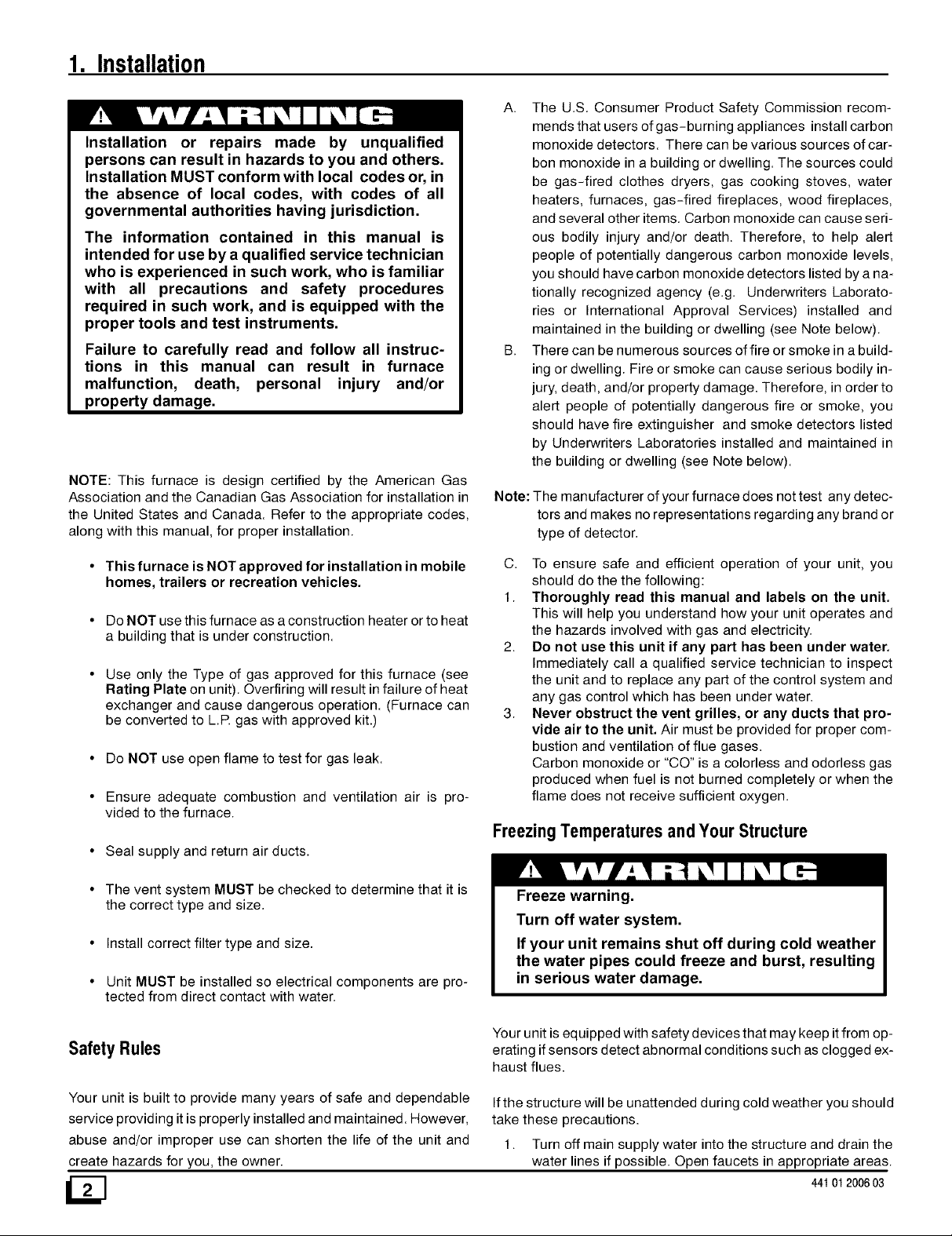
Fire or Explosion hazard.
This furnace is not designed for use in mobile
homes, trailers or recreational vehicles.
Such use could result in death, bodily injury
and/or property damage.
Printed in U.S.A. LP1 2/1/99 441 01 2006 03
12
13
14
17
18
19
Page 2
1. Installation
Installation or repairs made by unqualified
persons can result in hazards to you and others.
Installation MUST conform with local codes or, in
the absence of local codes, with codes of all
governmental authorities having jurisdiction.
The information contained in this manual is
intended for use by a qualified service technician
who is experienced in such work, who is familiar
with all precautions and safety procedures
required in such work, and is equipped with the
proper tools and test instruments.
Failure to carefully read and follow all instruc-
tions in this manual can result in furnace
malfunction, death, personal injury and/or
property damage.
NOTE: This furnace is design certified by the American Gas
Association and the Canadian Gas Association for installation in
the United States and Canada. Refer to the appropriate codes,
along with this manual, for proper installation.
A. The U.S. Consumer Product Safety Commission recom-
mends that users of gas-burning appliances install carbon
monoxide detectors. There can be various sources of car-
bon monoxide in a building or dwelling. The sources could
be gas-fired clothes dryers, gas cooking stoves, water
heaters, furnaces, gas-fired fireplaces, wood fireplaces,
and several other items. Carbon monoxide can cause seri-
ous bodily injury and/or death. Therefore, to help alert
people of potentially dangerous carbon monoxide levels,
you should have carbon monoxide detectors listed by a na-
tionally recognized agency (e.g. Underwriters Laborato-
ries or International Approval Services) installed and
maintained in the building or dwelling (see Note below).
B. There can be numerous sources of fire or smoke in a build-
ing or dwelling. Fire or smoke can cause serious bodily in-
jury, death, and/or property damage. Therefore, in order to
alert people of potentially dangerous fire or smoke, you
should have fire extinguisher and smoke detectors listed
by Underwriters Laboratories installed and maintained in
the building or dwelling (see Note below).
Note: The manufacturer of your furnace does not test any detec-
tors and makes no representations regarding any brand or
type of detector.
• This furnace is NOT approved for installation in mobile
homes, trailers or recreation vehicles.
• Do NOT use this furnace as a construction heater or to heat
a building that is under construction.
Use only the Type of gas approved for this furnace (see
Rating Plate on unit). Overfiring will result in failure of heat
exchanger and cause dangerous operation. (Furnace can
be converted to L.R gas with approved kit.)
• Do NOT use open flame to test for gas leak.
• Ensure adequate combustion and ventilation air is pro-
vided to the furnace.
• Seal supply and return air ducts.
• The vent system MUST be checked to determine that it is
the correct type and size.
• Install correct filter type and size.
• Unit MUST be installed so electrical components are pro-
tected from direct contact with water.
C. To ensure safe and efficient operation of your unit, you
should do the the following:
1. Thoroughly read this manual and labels on the unit.
This will help you understand how your unit operates and
the hazards involved with gas and electricity.
2. Do not use this unit if any part has been under water.
h-nrnediately call a qualified service technician to inspect
the unit and to replace any part of the control system and
any gas control which has been under water.
3. Never obstruct the vent grilles, or any ducts that pro-
vide air to the unit. Air must be provided for proper com-
bustion and ventilation of flue gases.
Carbon monoxide or "CO" is a colorless and odorless gas
produced when fuel is not burned completely or when the
flame does not receive sufficient oxygen.
FreezingTemperatures andYour Structure
Freeze warning.
Turn off water system.
If your unit remains shut off during cold weather
the water pipes could freeze and burst, resulting
in serious water damage.
Safety Rules
Your unit is built to provide many years of safe and dependable
service providing it is properly installed and maintained. However,
abuse and/or improper use can shorten the life of the unit and
create hazards for you, the owner.
/SJ
Your unit is equipped with safety devices that may keep itfrom op-
erating if sensors detect abnormal conditions such as clogged ex-
haust flues.
Ifthe structure will be unattended during cold weather you should
take these precautions.
1. Turn off main supply water into the structure and drain the
water lines if possible. Open faucets in appropriate areas.
44t 01200603
Page 3
Havesomeonecheckthestructurefrequentlyduringcold
weathertomakesureitiswarmenoughtopreventpipes
fromfreezing.Suggesttheycallaqualifiedserviceagency,
ifrequired.
Poison carbon monoxide gas hazard.
If this furnace is replacing a previously
common-vented furnace, it may be necessary to
resize the existing vent line and chimney to
prevent oversizing problems for the other
remaining appliances(s). See applicable codes
and Venting and Combustion Air Check in Gas
Vent Installation section.
Failure to properly vent this furnace or other
appliances can result in death, personal injury
and/or property damage.
iiiiiiiiiiiiiiiiiiiiiiii!:i¸ i¸I¸iiiiiiiiiiiiiiiiiiiii!i!!;_i¸ ii!i!i!i! i; !iiiii
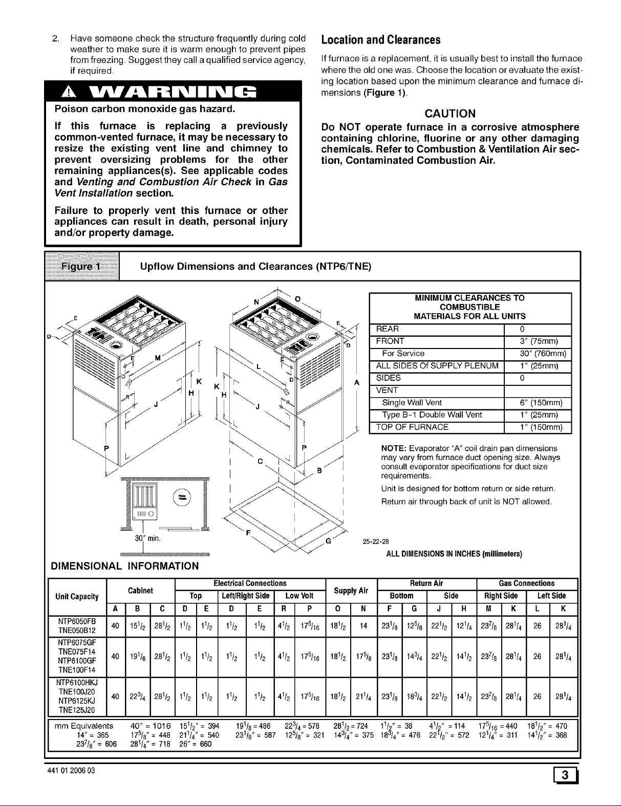
Upflow Dimensions and Clearances (NTP6/'rNE)
Locationand Clearances
Iffurnace is a replacement, it is usually best to install the furnace
where the old one was. Choose the location or evaluate the exist-
ing location based upon the minimum clearance and furnace di-
mensions (Figure 1).
CAUTION
Do NOT operate furnace in a corrosive atmosphere
containing chlorine, fluorine or any other damaging
chemicals. Refer to Combustion & Ventilation Air sec-
tion, Contaminated Combustion Air.
MINIMUM CLEARANCES TO
COMBUSTIBLE
MATERIALS FOR ALL UNITS
REAR 0
FRONT 3" (75mm)
For Service 30" (760mm)
ALL SIDES Of SUPPLY PLENUM 1" (25mm)
SIDES 0
VENT
Single Wall Vent 6" (150mm)
Type B-1 Double Wall Vent 1" (25mm)
TOP OF FURNACE 1" (150mm)
NOTE: Evaporator "A" coil drain pan dimensions
may vary from furnace duct opening size. Always
consult evaporator specifications for duct size
requirements.
Unit is designed for bottom return or side return.
Return air through back of unit is NOT allowed.
25-22-28
ALL DIMENSIONS IN INCHES (millimeters)
DIMENSIONAL INFORMATION
UnitCapacity
NTP6050FB
TNE050B12
NTP6075GF
TNE075F14
NTP6100GF 40 191/8 281/2 11/2 11/2 11/2 11/2 41/2 175/16 181/2 175/8 231/8 t43/4 221/2 141/2 237/8 281/4 26 281/.
TNE100F14
NTP6100HKJ
TNE10OJ20
NTP6125KJ
TNE125J20
mm Equivalents 40"= t016 151/2"= 394 191/8=486 223/4=578 281/2,_724 11/o2"= 38 41/2" =1t4 175/16=440 181/2"= 470
14"= 365 175/8"= 448 211/4"= 540 231/8'= 587 125/8"= 321 143/4 = 375 18_/4"= 476 22_/2"= 572 121/4 = 311 141/2"= 368
237/8"= 606 281/4"= 718 26"= 660
Cabinet
B C
A
40 14
151/2 281t2
40 223/4 281/2 11/2 11/2 11/2 11/2 41/2 175/16 181/2 211/4 231/8 t83/4 221/2 141/2 237/8 281/4 26 281/.
11/2 11/2 11/2 11/2 41/2 175/16
ElectricalConnections
Top Left/RightSide LowVolt
D E D E R P
SupplyAir
0 N
181/2
ReturnAir
Bottom Side
F G J H
231/8 t25/8 221/2 121/4
GasConnections
RightSide LeftSide
M K L K
237/8 281/4 26 2811,
44101 200603
Page 4
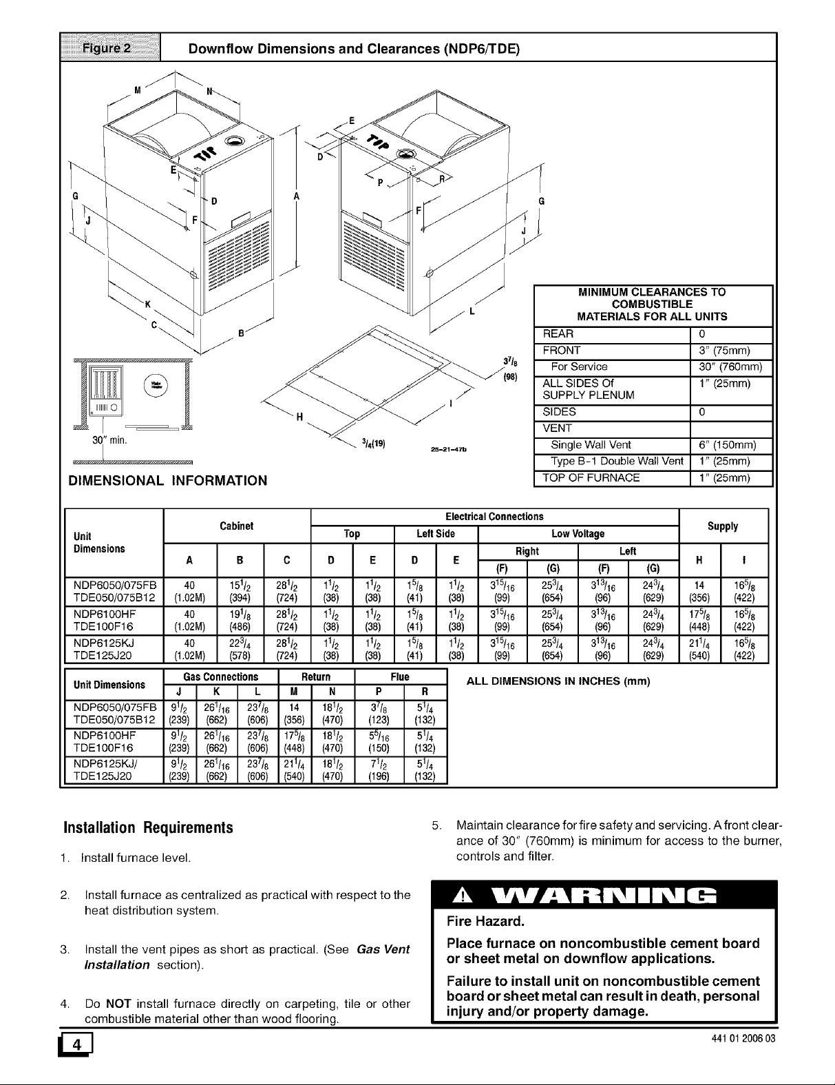
Downflow Dimensions and Clearances (NDP6/'rDE)
A o.
_'_'_ _ _1 _ -°" "< _ _ MINIMUM CLEARANCES TO
\K _ /I _ __ / / COMBUSTIBLE
_ \ _ _1 _ / / L MATERIALS FOR ALL UNITS
_,J'_ _ FRONT 3' (75mm)
_ _''"""""" _ ._ "''_ _ / 37'8 For Service 30" (760mm)
(,_ /._ _._" _ (98) ALLSIDESOf 1" (25mm)
_ "_ _ _'_f _1/I SUPPLY PLENUM
S,DES o
o ° VENT
/ REAR 0
' " " _'_- 3/4(19) 6" (150mm)
DIMENSIONAL INFORMATION TOP OF FURNACE 1" (25mm)
Unit
Dimensions
NDP6050/075FB 40 151/2 281/2 1_/2 11/2 15/8 11/2 14 165/8
TDE050/075Bt2 (1.02M) (394) (724) (38) (38) (4t) (38) (356) (422)
NDP6100HF 40 191/8 281/2 11/2 11/2 15/8 11/2 175/8 165/8
TDE100F16 (1.02M) (486) (724) (38) (38) (4t) (38) (448) (422)
NDP6125KJ 40 223/4 281/2 11/2 11/2 15/8 11/2 211/4 165/8
TDE125J20 (1.02M) (578) (724) (38) (38) (4t) (38) (540) (422)
Unit Dimensions
NDP6050/075FB
TDE050/075Bt 2
NDP6100HF
TDE100F16
NDP6125KJ/
TDE125J20
J K L M N P R
91/2 261/16 237/8 14 181/2 37/8 51/4
(239) (662) (606) (356) (470) (123) (132)
91/2 261/16 237/8 175/8 181/2 55/16 51/4
(239) (662) (606) (448) (470) (150) (132)
91/2 261/16 237/8 211/4 181/2 71/2 51/4
(239) (662) (606) (540) (470) (196) (132)
Cabinet
GasConnections Return Flue
Top Left Side
25-2_-47b Single Wall Vent
ElectricalConnections
D E
(F) (G) (F) (G)
315/16 253/4 313/16 243/4
(99) (654) (96) (629)
315/16 253/4 313/16 243/4
(99) (654) (96) (629)
315/16 253/4 313/16 243/4
(99) (654) (96) (629)
ALL DIMENSIONS IN INCHES (mm)
Type B-1 Double Wall Vent 1" (25mm)
LowVoltage
Right Left
Supply
H I
Installation Requirements
1. Install furnace level.
Install furnace as centralized as practical with respect to the
heat distribution system.
Install the vent pipes as short as practical. (See Gas Vent
Installation section).
Do NOT install furnace directly on carpeting, tile or other
combustible material other than wood flooring.
5. Maintain clearance for fire safety and servicing. A front clear-
ance of 30" (760mm) is minimum for access to the burner,
controls and filter.
Fire Hazard.
Place furnace on noncombustible cement board
or sheet metal on downflow applications.
Failure to install unit on noncombustible cement
board or sheet metal can result in death, personal
injury and/or property damage.
44t 012006 03
Page 5
6. Use a raised base if the floor is damp or wet at times.
Residential garage installations require:
• Burners and ignition sources installed at least 18" (457mm)
above the floor.
• Furnace must be located or physically protected from pos-
sible damage by a vehicle.
Horizontal FurnaceInstallation
IMPORTANT
NOTE: Inspect unit rating plate to be certain model number be-
gins with "NTP6 or TNE". This identifies unit as horizontally
mountable. If unit does NOT bear this designation, you may NOT
mount this unit horizontally. Horizontal furnace may not be
mounted on its back or front.
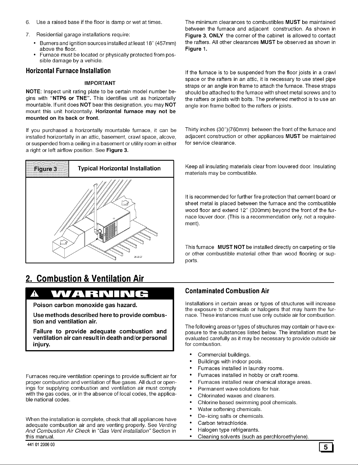
The minimum clearances to combustibles MUST be maintained
between the furnace and adjacent construction. As shown in
Figure 3, ONLY the corner of the cabinet is allowed to contact
the rafters. All other clearances MUST be observed as shown in
Figure 1.
If the furnace is to be suspended from the floor joists in a crawl
space or the rafters in an attic, it is necessary to use steel pipe
straps or an angle iron frame to attach the furnace. These straps
should be attached to the furnace with sheet metal screws and to
the rafters or joists with bolts. The preferred method is to use an
angle iron frame bolted to the rafters or joists.
If you purchased a horizontally mountable furnace, it can be
installed horizontally in an attic, basement, crawl space, alcove,
or suspended from a ceiling in a basement or utility room in either
a right or left airflow position. See Figure 3.
Typical Horizontal Installation
2. Combustion&VentilationAir
Thirty inches (30")(760mm) between the front ofthe furnace and
adjacent construction or other appliances MUST be maintained
for service clearance.
Keep all insulating materials clear from Iouvered door. Insulating
materials may be combustible.
It is recommended for further fire protection that cement board or
sheet metal is placed between the furnace and the combustible
wood floor and extend 12" (300mm) beyond the front of the fur-
nace louver door. (This is a recommendation only, not a require-
ment).
This furnace MUST NOT be installed directly on carpeting or tile
or other combustible material other than wood flooring or sup-
ports.
Contaminated CombustionAir
Poison carbon monoxide gas hazard.
Use methods described here to provide combus-
Installations in certain areas or types of structures will increase
the exposure to chemicals or halogens that may harm the fur-
nace. These instances must use only outside air for combustion.
tion and ventilation air.
Failure to provide adequate combustion and
ventilation air can result in death and/or personal
injury.
Furnaces require ventilation openings to provide sufficient air for
proper combustion and ventilation of flue gases. All duct or open-
ings for supplying combustion and ventilation air must comply
with the gas codes, or in the absence of local codes, the applica-
ble national codes.
When the installation is complete, check that all appliances have
adequate combustion air and are venting properly. See Venting
And Combustion Air Check in "Gas Vent Installation" Section in
this manual.
44101 2006 03 [_
The following areas or types of structures may contain or have ex-
posure to the substances listed below. The installation must be
evaluated carefully as it may be necessary to provide outside air
for combustion.
• Commercial buildings.
• Buildings with indoor pools.
• Furnaces installed in laundry rooms.
• Furnaces installed in hobby or craft rooms.
• Furnaces installed near chemical storage areas.
• Permanent wave solutions for hair.
• Chlorinated waxes and cleaners.
• Chlorine based swimming pool chemicals.
• Water softening chemicals.
• De-icing salts or chemicals.
• Carbon tetrachloride.
• Halogen type refrigerants.
• Cleaning solvents (such as perchloroethylene).
Page 6
• Printing inks, paint removers, varnishes, etc..
Air Openingsand Connecting Ducts
• Hydrochloric acid.
• Sulfuric Acid.
• Solvent cements and glues.
• Antistatic fabric softeners for clothes dryers.
• Masonry acid washing materials.
1. Total input rating for all gas appliances MUST be considered
when determining free area of openings.
2. Connect ducts or openings directly to outside.
3. When screens are used to cover openings, the openings
MUST be no smaller than 1/4" (6mm) mesh.
ConfinedSpace Installation
4. The minimum dimension of rectangular air ducts MUST NOT
be less than 3" (75mm).
NOTE: A confined space is defined as an area with less than 50 5. When sizing grille or louver, use the free area of opening. If
cubic feet(1.4m 3) per 1,000 BTUH input rating for all gas ap- free area is NOT stamped or marked on grill or louver, as-
pliances installed in the area. sume a 20% free area for wood and 60% for metal.
iiiiiiiii_;;;;;;;; ;;;;; ;;;;;;;;;; ;; ;;;i ¸ ;
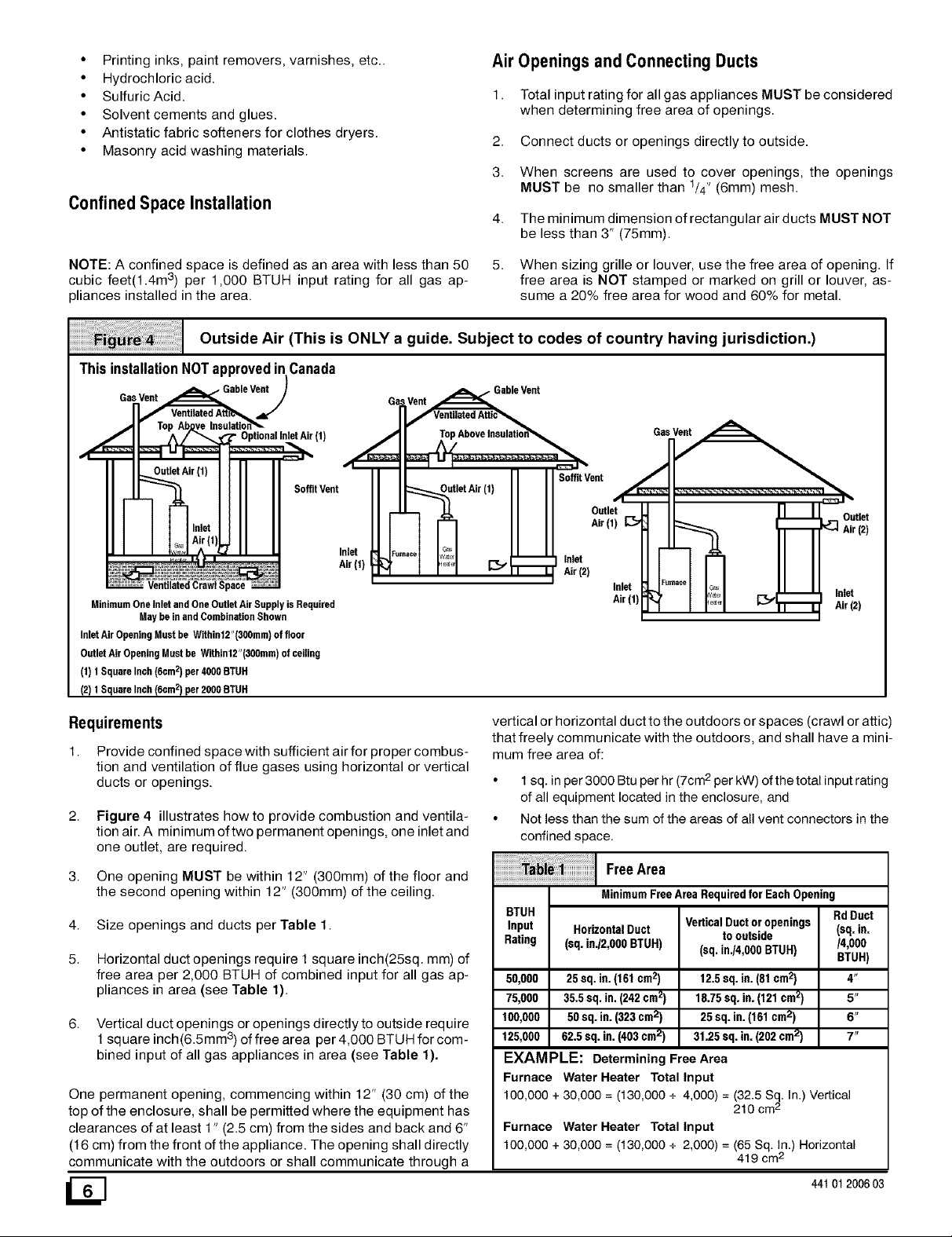
Outside Air (This is ONLY a guide. Subject to codes of country having jurisdiction.)
This installation NOT approved in Canada
_ L_. " Optional Inlet Air (1)
fl
_F'_ jr(l) Sofit Vent
I ' ' n So fflit ent
ut'etAir''II L
I ,_LL_, .LL II I Outlet
1 Inlet
VentilatedCrawlSpace
MinimumOneinletand OneOutletAirSupplyis Required
May be in andCombinationShown
inletAir OpeningMustbe Within12"(300mm)of floor
OutletAir Opening Must be Withint2"(300mm) of ceiling
(1) 1SquareInch(6cm2) per 4000BTUH
(2) 1SquareInch(6cm2) per 2000BTUH
INIII
Inlet
]_,....... I r_l r_l-_" Inlet
Air (1)
1"1 I I I _ I I L Air(2)
Requirements
1.
Provide confined space with sufficient air for proper combus-
tion and ventilation of flue gases using horizontal or vertical
ducts or openings.
Figure 4 illustrates how to provide combustion and ventila-
tion air. A minimum oftwo permanent openings, one inlet and
one outlet, are required.
3.
One opening MUST be within 12" (300mm) of the floor and
the second opening within 12" (300mm) of the ceiling.
4. Size openings and ducts per Table 1.
5. Horizontal duct openings require 1 square inch(25sq, mm) of
free area per 2,000 BTUH of combined input for all gas ap-
pliances in area (see Table 1).
6. Vertical duct openings oropenings directly to outside require
1square inch(6.5mm 3) of free area per 4,000 BTUH for com-
bined input of all gas appliances in area (see Table 1).
One permanent opening, commencing within 12" (30 cm) of the
top of the enclosure, shall be permitted where the equipment has
clearances of at least 1" (2.5 cm) from the sides and back and 6"
(16 cm) from the front of the appliance. The opening shall directly
communicate with the outdoors or shall communicate through a
/SJ
Inlet
Air (1)
vertical or horizontal duct to the outdoors or spaces (crawl or attic)
that freely communicate with the outdoors, and shall have a mini-
mum free area of:
• 1 sq. in per 3000 Btu per hr 2(7cm per kW) of the total input rating
of all equipment located in the enclosure, and
• Not less than the sum of the areas of all vent connectors in the
confined space.
_i_i I FreeArea
MinimumFreeArea Requiredfor Each Opening
BTUH
Input HorizontalDuct
Rating (sq. in./2,000BTUH)
50,000 25sq. in.(161cm2)
75,000 35.5 sq. in. (242cm2)
100,000 50sq. in.(323cm2)
125,000 62.5 sq. in.(403 cm2)
VerticalDuctoropenings
to outside
(sq. in.t4,OO0BTUH)
12.5sq. in.(81cm2)
18.75 sq.in. (121 cm2)
25sq. in.(161cm2)
31.25 sq.in. (202 cm2)
EXAMPLE: Determining Free Area
Furnace Water Heater Total Input
100,000 + 30,000 = (t30,000 + 4,000) = (32.5 Sq. In.) Vertical
Furnace Water Heater Total Input
100,000 + 30,000 = (t30,000 + 2,000) = (65 Sq. In.) Horizontal
210 cm 2
419 cm2
Rd Duct
(sq.in.
/4,000
BTUH)
4"
5"
6"
7"
44t 012006 03
Page 7

Unconfined Space Installation
Poison carbon monoxide gas hazard.
Most homes will require additional air.
An unconfined space or homes with tight
construction may not have adequate air infiltra-
tion for proper combustion and ventilation of
flue gases.
Failure to supply additional air by means of ven-
tilation grilles or ducts could result in death and/
or personal injury.
An unconfined space is defined as an area having a minimum vol-
ume of 50 cubic feet(1.4m 3) per 1,000 Btuh total input rating for all
gas appliances in area.
Adjoining rooms can be considered part of an unconfined area if
there are no doors between rooms.
An attic or crawl space may be considered an unconfined space
provided there are adequate ventilation openings directly to out-
doors. Openings MUST remain open and NOT have any means
of being closed off. Ventilation openings to outdoors MUST be at
least 1 square inch (25mm 2) of free area per 4,000 BTUH of total
input rating for all gas appliances in area.
In unconfined spaces, infiltration should be adequate to provide
air for combustion, ventilation and dilution of flue gases. However,
in buildings with unusually tight construction, additional air MUST
be provided using the methods described in section titled Con-
fined Space Installation:
Unusually tight construction is defined as: Construction with
1 Walls and ceilings exposed to the outside have a continuous,
sealed vapor barrier. Openings are gasketed or sealed and
2 Doors and openable windows are weather stripped and
Other openings are caulked or sealed. These include joints
around window and door frames, between sole plates and
floors, between wall-ceiling joints, between wall panels, at
penetrations for plumbing, electrical and gas lines, etc.
VentilationAir
Some provincial codes and local municipalities require ventilation
or make-up air be brought into the conditioned space as replace-
ment air. Whichever method is used, the mixed return air temper-
ature across the heat exchanger MUST not fall below 60°F (15 ° c)
or flue gases will condense in the heat exchanger. This will short-
en the life of the heat exchanger and possibly void your warranty.
3. GasVentInstallation
Poison carbon monoxide gas, fire and explo-
sion hazard.
Read and follow all instructions in this section.
Failure to properly vent this furnace can result in
death, personal injury and/or property damage.
Install the vent in compliance with codes of the country having ju-
risdiction, local codes or ordinances and these instructions.
These fan assisted combustion furnaces have been classified as
Category ][appliances which means that they MUST operate with
a negative vent pressure.
CategoryI Safe Venting Requirements
NOTE: The following instructions comply with the United States
National Fuel Gas Code. Based on the highest input rate on the
furnace rating plate.
If a Category ][vent passes through an attic, any concealed
space or floor, use ONLY Type B or Type L double wall vent
pipe. If vent pipe passes through interior wall, use type B vent
pipe with ventilated thimble ONLY.
2. Do NOT vent furnace into any chimney serving an open fire-
place or solid fuel burning appliance.
3. Use the same diameter Category ][connector or pipe as per-
mitted by the United States National Fuel Gas Code vent-
ing tables.
44101200603
4. Keep vertical Category ][vent pipe or vent connector runs as
short and direct as possible.
5.
Vertical outdoor runs of type B or ANY single wall vent pipe
below the roof line are NOT permitted.
6.
Slope all horizontal runs up away from furnace a minimum of
1/4" (6mm) per foot.
7.
Support all horizontal vent pipe every 6' (2m) using proper
clamps and metal straps.
8.
Check existing gas vent or chimney to ensure they meet
clearances and local codes.
The furnace MUST be connected to a factory built chimney or
vent complying with a recognized standard. Venting into a
masonry or concrete chimney is only permitted as out-
lined in the United States National Fuel Gas Code vent-
ing tables or Masonry Chimney section in these
instructions.
Poison carbon monoxide gas hazard.
If this furnace is replacing a previously
common-vented furnace, it may be necessary
to resize the existing chimney liner or vent to
prevent over sizing problems for the other
remaining appliances(s). See codes of country
having jurisdiction.
Failure to properly vent this furnace or other
appliances can result in death, personal injury
and/or property damage.
EZ3
Page 8
Venting and CombustionAir Check
NOTE: Ifthis installation removes an existing furnace from a vent-
ing system serving one or more other appliances, and to make
sure there is adequate combustion air for all appliances, MAKE
THE FOLLOWING CHECK.
1. Seal any unused openings in the venting system.
Visually inspect the venting system for proper size and hori-
zontal pitch to ensure there is no blockage or restriction, leak-
age, corrosion or other deficiencies which could cause an
unsafe condition.
7. After it has been determined that each appliance vents prop-
erly, return doors, windows, appliances etc. to their normal
condition.
8. If improper venting is observed, the cause MUST be cor-
rected.
NOTE: If flame pulls towards draft hood, this indicates sufficient
infiltration air.
Venting to Existing MasonryChimney
Insofar as is practical, close all doors and windows and all
doors between the space in which the appliance(s) remain-
ing connected to the venting system are located and other
spaces of the building.
Turn on clothes dryers and any appliance not connected to
the venting system. Turn on any exhaust fans, such as range
hoods and bathroom exhausts, so they will operate at maxi-
mum speed. Do not operate a summer exhaust fan. Close
fireplace dampers.
5. Follow the lighting instructions for each appliance being in-
spected. Adjust thermostat so appliance(s) will operate con-
tinuously.
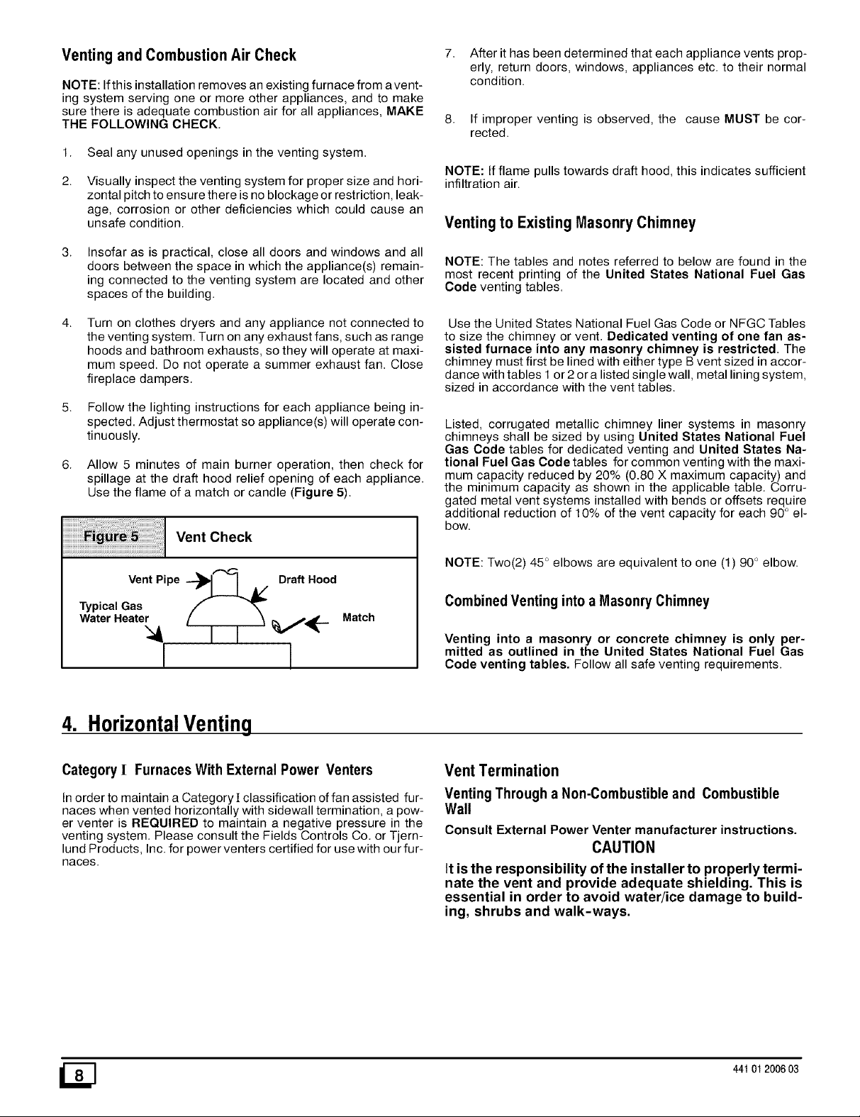
6. Allow 5 minutes of main burner operation, then check for
spillage at the draft hood relief opening of each appliance.
Use the flame of a match or candle (Figure 5).
Vent Check
Vent Pipe ---_ J A/ Draft Hood
Typical Gas
Water Heater
Match
I I
NOTE: The tables and notes referred to below are found in the
most recent printing of the United States National Fuel Gas
Code venting tables.
Use the United States National Fuel Gas Code or NFGC Tables
to size the chimney or vent. Dedicated venting of one fan as-
sisted furnace into any masonry chimney is restricted. The
chimney must first be lined with either type B vent sized in accor-
dance with tables 1 or 2or a listed single wall, metal lining system,
sized in accordance with the vent tables.
Listed, corrugated metallic chimney liner systems in masonry
chimneys shall be sized by using United States National Fuel
Gas Code tables for dedicated venting and United States Na-
tional Fuel Gas Code tables for common venting with the maxi-
mum capacity reduced by 20% (0.80 X maximum capacity) and
the minimum capacity as shown in the applicable table. Corru-
gated metal vent systems installed with bends or offsets require
additional reduction of 10% of the vent capacity for each 90 ° el-
bow.
NOTE: Two(2) 45 ° elbows are equivalent to one (1 90° elbow.
Combined Ventinginto a Masonry Chimney
Venting into a masonry or concrete chimney is only per-
mitted as outlined in the United States National Fuel Gas
Code venting tables. Follow all safe venting requirements.
4. HorizontalVenting
Category [ Furnaces With External Power Venters
Inorder to maintain a Category][ classification offan assisted fur-
naces when vented horizontally with sidewall termination, a pow-
er venter is REQUIRED to maintain a negative pressure in the
venting system. Please consult the Fields Controls Co. or Tjern-
lund Products, Inc. for power venters certified for use with our fur-
naces.
_] 44t 012006 03
Vent Termination
Venting Through a Non-Combustible and Combustible
Wall
Consult External Power Venter manufacturer instructions.
CAUTION
It isthe responsibility of the installer to properly termi-
nate the vent and provide adequate shielding. This is
essential in order to avoid water/ice damage to build-
ing, shrubs and walk-ways.
Page 9

5. GasSupplyand Piping
Orifice Sizing
Poison carbon monoxide gas, fire and explosion
hazard.
Models designated for Natural Gas are to be used
with Natural Gas ONLY, unless properly con-
verted to use with LP gas.
Failure to follow these instructions can result in
death, personal injury and/or property damage.
Gas Supply Requirements
• Use only the Type of gas approved for this furnace. See rat-
ing plate for approved gas type.
• Gas input must not exceed the rated input shown on the rat-
ing plate. Overfiring will result in failure of heat exchanger
and cause dangerous operation.
• De not allow minimum supply pressure to vary downward.
Doing so will decrease input to furnace. Refer to Table 2 for
Gas supply and manifold pressures.
Pressures
Gas Supply Pressure
Type
Natural 7" 14" 4.5"
Propane 11" 14" 11"
Recom- Max. Min.
mended
(1.7 kPa) (3.5 kPa) (1.1 kPa)
(2.7 kPa) (3.5 kPa) (2.7 kPa)
Manifold
Pressure
High Low
3.5" 1.7"
(0.9 (0.42
kPa) kPa)
10" 4.3"
(2.5 (1.07
kPa) kPa)
Natural Gas Input Rating Check
The gas meter can be used to measure input to furnace. Rating is
based on a natural gas BTU content of 1,000 BTU's per cubic foot.
Check with gas supplier for actual BTU content.
1. Turn OFF gas supply to all appliances other than furnace and
start furnace.
2. Time how many seconds it takes the smallest dial on the gas
meter to make one complete revolution. Refer to Example.
Note: If meter uses a 2 cubic foot dial, divide results (se-
conds) by two.
Example
Natural Gas No. of Seconds Time Per Cubic
BTU Content Per Hour Foot in Seconds
1,000 3,600 48
1,000 x 3,600 ÷ 48 = 75,000 BTUH
3.
Relight all appliances and ensure all pilots are operating.
BTU Per
Hour
75,000
NOTE: Factory sized orifices for natural and LP gas are listed in
the furnace Technical Support manual.
Ensure furnace is equipped with the correct main burner orifices.
Refer to Table 3 & Table 4 for correct orifice size for a given heat-
ing value and specific gravity for natural and propane gas.
OperationAbove 2000' Altitude
Fire, Explosion, Poison carbon monoxide gas haz-
ard.
This conversion shall be done by a qualified ser-
vice agency in accordance with the Manufactur-
er's instructions and all applicable codes and re-
quirements, or in the absence of local codes, the
applicable national codes.
Failure to follow these instructions exactly can re-
sult in death, personal injury and/or property dam-
age.
These units may be used at full input rating when installed at alti-
tudes up to 2000'. When installed above 2000', the high fire input
must be decreased 2% (natural) or 4% (LP) for each 1000' above
sea level. This may be accomplished by a simple adjustment of
manifold pressure or an orifice change, or a combination of a
pressure adjustment and an orifice change. The changes re-
quired depend on the installation altitude and the heating value of
the fuel. Table 3 & Table 4 show the proper furnace manifold
pressure and gas orifice size to achieve proper performance
based on elevation above sea level for both natural gas and pro-
pane.
To use the natural gas table, first consult your local gas utility for
the heating value of the gas supply. Select the heating value on
the vertical border and follow across the table until the appropriate
elevation for the installation is reached. The first value in the box
at the intersection of the heating value and elevation will be the
manifold pressure required. If a gas orifice change is also re-
quired, the box is shaded. The required orifice size is shown at the
bottom of the table.
Sea Level
High Altitude Input Rate = Nameplate x (Multiplier)
Input Rate
Elevation
2000'-2999'
3000'-3999'
4000'-4999'
5000'-5999'
6000'-6999'
7000'-7999'
High Altitude Multiplier
Natural LP Gas
0.96 0.92
0.94 0.88
0.92 0.84
0.90 0.80
0.88 0.76
0.86 0.72
44101 2006 03 [_
Page 10
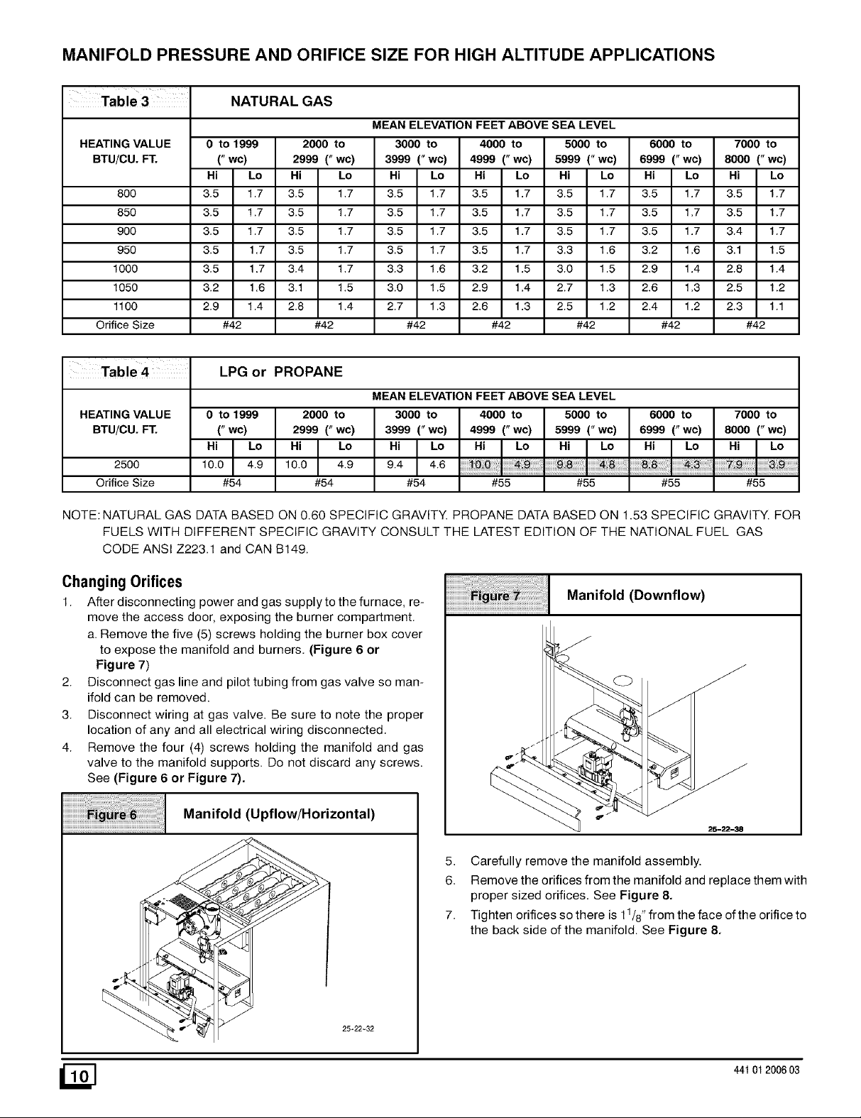
MANIFOLD PRESSURE AND ORIFICE SIZE FOR HIGH ALTITUDE APPLICATIONS
NATURAL GAS
MEAN ELEVATION FEET ABOVE SEA LEVEL
HEATING VALUE
BTUiCU. FT.
8OO
85O
900
950
1000
1050
1100
Orifice Size
HEATING VALUE
BTUiCU. FT.
0 to 1999
("wc)
Hi Lo
3.5 1.7
3.5 1.7
3.5 1.7
3.5 1.7
3.5 1.7
3.2 1.6
2.9 1.4
#42
2999 (" wc)
Hi Lo
3.5 1.7
3.5 1.7
3.5 1.7
3.5 1.7
3.4 1.7
3.1 1.5
2.8 1.4
LPG or PROPANE
0 to 1999
("wc)
2999 (" wc)
2000 to
#42
2000 to
3000 to 4000 to 5000 to
3999 (" wc) 4999 (" wc) 5999 (" wc)
Hi Lo
3.5 1.7
3.5 1.7
3.5 1.7
3.5 1.7
3.3 1.6
3.0 1.5
2.7 1.3
#42
MEAN ELEVATION FEET ABOVE SEA LEVEL
3000 to 4000 to 5000 to
3999 (" wc) 4999 (" wc) 5999 (" wc)
Hi Lo
3.5 1.7
3.5 1.7
3.5 1.7
3.5 1.7
3.2 1.5
2.9 1.4
2.6 1.3
#42
Hi Lo
3.5 1.7
3.5 1.7
3.5 1.7
3.3 1.6
3.0 1.5
2.7 1.3
2.5 1.2
#42
6000 to
6999 (" wc)
Hi Lo
3.5 1.7
3.5 1.7
3.5 1.7
3.2 1.6
2.9 1.4
2.6 1.3
2.4 1.2
#42
6000 to
6999 (" wc)
7000 to
8000 (" wc)
Hi Lo
3.5 1.7
3.5 1.7
3.4 1.7
3.1 1.5
2.8 1.4
2.5 1.2
2.3 1.1
#42
7000 to
8000 ("wc)
2500
Orifice Size
Hi I Lo10.0 4.9
#54
Hi I Lo10.0 4.9
#54
Hi I Lo9.4 4.6
#54 #55 #55
#55 #55
NOTE: NATURAL GAS DATA BASED ON 0.60 SPECIFIC GRAVITY. PROPANE DATA BASED ON 1.53 SPECIFIC GRAVITY. FOR
FUELS WITH DIFFERENT SPECIFIC GRAVITY CONSULT THE LATEST EDITION OF THE NATIONAL FUEL GAS
CODE ANSI Z223.1 and CAN B149.
ChangingOrifices
1. After disconnecting power and gas supply to the furnace, re-
move the access door, exposing the burner compartment.
a. Remove the five (5) screws holding the burner box cover
to expose the manifold and burners. (Figure 6 or
Figure 7)
2. Disconnect gas line and pilot tubing from gas valve so man-
ifold can be removed.
3. Disconnect wiring at gas valve. Be sure to note the proper
location of any and all electrical wiring disconnected.
4. Remove the four (4) screws holding the manifold and gas
valve to the manifold supports. Do not discard any screws.
See (Figure 6 or Figure 7).
Manifold (Upflow/Horizontal)
5. Carefully remove the manifold assembly.
6. Remove the orifices from the manifold and replace them with
proper sized orifices. See Figure 8.
7. Tighten orifices so there is 11/8"from the face of the orifice to
the back side of the manifold. See Figure 8.
Manifold (Downflow)
25-22-32
_] 44t 012006 03
Page 11
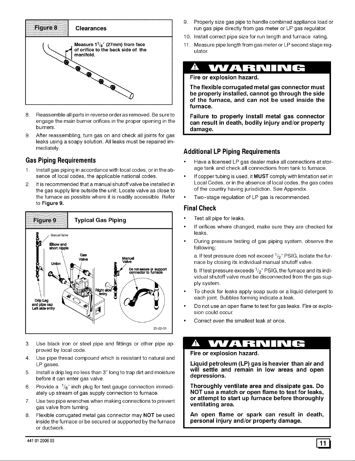
Clearances
Measure11/8"(27mm)from face
oforifice to the back side of the
manifold.
8. Reassemble all parts in reverse order as removed. Be sure to
engage the main burner orifices in the proper opening in the
burners.
9. After reassembling, turn gas on and check all joints for gas
leaks using a soapy solution. All leaks must be repaired im-
mediately.
Gas Piping Requirements
1. Install gas piping in accordance with local codes, or in the ab-
sence of local codes, the applicable national codes.
2. Itis recommended that a manual shutoff valve be installed in
the gas supply line outside the unit. Locate valve as close to
the furnace as possible where it is readily accessible. Refer
to Figure 9.
9. Properly size gas pipe to handle combined appliance load or
run gas pipe directly from gas meter or LP gas regulator.
10. Install correct pipe size for run length and furnace rating.
11. Measure pipe length from gas meter or LP second stage reg-
ulator.
Fire or explosion hazard.
The flexible corrugated metal gas connector must
be properly installed, cannot go through the side
of the furnace, and can not be used inside the
furnace.
Failure to properly install metal gas connector
can result in death, bodily injury and/or property
damage.
Additional LP Piping Requirements
• Have a licensed LP gas dealer make all connections at stor-
age tank and check all connections from tank to furnace.
• If copper tubing is used, it MUST comply with limitation set in
Local Codes, or in the absence of local codes, the gas codes
of the country having jurisdiction. See Appendix.
• Two-stage regulation of LP gas is recommended.
Final Check
Typical Gas Piping
Bbow_
nipple
Valve
25-22_31
3. Use black iron or steel pipe and fittings or other pipe ap-
proved by local code.
4. Use pipe thread compound which is resistant to natural and
LP gases.
5. Install a drip leg no less than 3" long to trap dirt and moisture
before it can enter gas valve.
6. Provide a 1/8" inch plug for test gauge connection immedi-
ately up stream of gas supply connection to furnace.
7. Use two pipe wrenches when making connections to prevent
gas valve from turning.
8. Flexible corrugated metal gas connector may NOT be used
inside the furnace or be secured or supported by the furnace
or ductwork.
• Test all pipe for leaks.
• If orifices where changed, make sure they are checked for
leaks.
• During pressure testing of gas piping system, observe the
following:
a. If test pressure does not exceed 1/2" PSIG, isolate the fur-
nace by closing its individual manual shutoff valve.
b. Iftest pressure exceeds 1/2"PSIG, the furnace and its indi-
vidual shutoff valve must be disconnected from the gas sup-
ply system.
• To check for leaks apply soap suds or a liquid detergent to
each joint. Bubbles forming indicate a leak.
• Do not use an open flame to test for gas leaks. Fire or explo-
sion could occur.
• Correct even the smallest leak at once.
Fire or explosion hazard.
Liquid petroleum (LP) gas is heavier than air and
will settle and remain in low areas and open
depressions.
Thoroughly ventilate area and dissipate gas. Do
NOT use a match or open flame to test for leaks,
or attempt to start up furnace before thoroughly
ventilating area.
An open flame or spark can result in death,
personal injury and/or property damage.
44101 2006 03 [_
Page 12
6. ElectricalWiring
Power Supply Wiring
The furnace MUST be electrically wired and grounded in accor-
dance with local codes, or in the absence of local codes, the appli-
cable national codes.
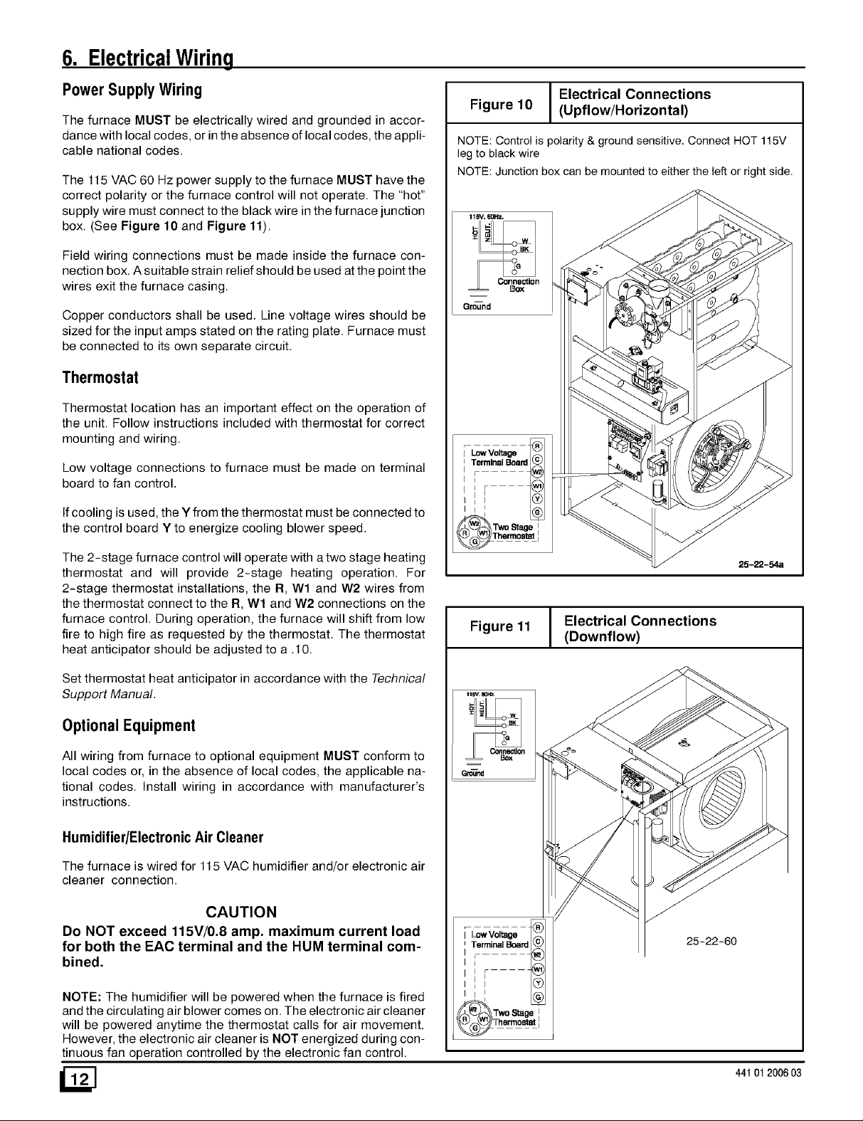
The 115 VAC 60 Hz power supply to the furnace MUST have the
correct polarity or the furnace control will not operate. The "hot"
supply wire must connect to the black wire in the furnace junction
box. (See Figure 10 and Figure 11).
Field wiring connections must be made inside the furnace con-
nection box. A suitable strain relief should be used at the point the
wires exit the furnace casing.
Copper conductors shall be used. Line voltage wires should be
sized for the input amps stated on the rating plate. Furnace must
be connected to its own separate circuit.
Thermostat
Thermostat location has an important effect on the operation of
the unit. Follow instructions included with thermostat for correct
mounting and wiring.
Low voltage connections to furnace must be made on terminal
board to fan control.
Ifcooling is used, the Y from the thermostat must be connected to
the control board Y to energize cooling blower speed.
The 2-stage furnace control will operate with a two stage heating
thermostat and will provide 2-stage heating operation. For
2-stage thermostat installations, the R, Wl and W2 wires from
the thermostat connect to the R, Wl and W2 connections on the
furnace control. During operation, the furnace will shift from low
fire to high fire as requested by the thermostat. The thermostat
heat anticipator should be adjusted to a .10.
Electrical Connections
Figure 10 (Upflow/Horizontal)
NOTE: Control is polarity & ground sensitive. Connect HOT 115V
leg to black wire
NOTE: Junction box can be mounted to either the left or right side.
115"V.60Hz.
=
Gm=und
Ilr
Two Stage t
@ ormo,= 1
25-22-54a
Figure 11
Electrical Connections
(Downflow)
Set thermostat heat anticipator in accordance with the Technical
Support Manual.
OptionalEquipment
All wiring from furnace to optional equipment MUST conform to
local codes or, in the absence of local codes, the applicable na-
tional codes. Install wiring in accordance with manufacturer's
instructions.
Humidifier/ElectronicAir Cleaner
The furnace is wired for 115 VAC hurnidifier and/or electronic air
cleaner connection.
CAUTION
Do NOT exceed 115V/0.8 amp. maximum current load
for both the EAC terminal and the HUM terminal com-
bined.
NOTE: The humidifier will be powered when the furnace is fired
and the circulating air blower comes on. The electronic air cleaner
will be powered anytime the thermostat calls for air movement.
However, the electronic air cleaner is NOT energized during con-
tinuous fan operation controlled by the electronic fan control.
/2N
Lowvol
I _ag
Terrnina_Board @ 25-22-60
I,
:=r ÷
Ill ®
_Two Stage i
44t 012006 03
Page 13

7. DuctworkandFilter(Upflow/Horizontal)on NTP6/TNE
If separate evaporator and blower unit is used, install good
sealing dampers for air flow control. Chilled air going through
Poison carbon monoxide gas hazard.
Do NOT draw return air from inside a closet or util-
ity room where furnace is located, Return air duct
MUST be sealed to furnace casing,
Failure to properly seal duct can result in death
and/or personal injury,
the furnace could cause condensation and shorten furnace
life. Dampers (purchased locally) can be either automatic or
manual. Manually operated dampers MUST be equipped
with a means to prevent furnace or air conditioning operation
unless damper is in the full heat or cool position.
DuctConnections
This furnace may be installed in only a bottom or side return ap-
plication. Return air through the back of the unit is NOT allowed.
Side connections can be made by cutting out the embossed area
shown in Figure 12.
Cutting Side Return Air Opening
Starting
Bottom returns can be made by removing the knockout panel in
the furnace base. Do NOT remove knock-out except for a bottom
return.
DuctDesignon NTP6iTNE
Design and install air distribution system to comply with Air Condi-
tioning Contractors of America manuals or other approved meth-
ods that conform to local codes and good trade practices.
Poison carbon monoxide gas hazard.
Cool air passing over heat exchanger can cause
condensate to form resulting in heat exchanger
failure.
This could result in death and/or personal injury,
• Installation of locking-type dampers are recommended in all
branches, or in individual ducts to balance system's air flow.
• Non-combustible, flexible duct connectors are recom-
mended for return and supply connections to furnace.
• If air return grille is located close to the fan inlet, install at least
one, 90° air turn between fan and inlet grille to reduce noise.
Ductwork installed in attic, or exposed to outside tempera-
tures requires a minimum of 2" of insulation with outdoor
type vapor barrier.
Ductwork installed in an indoor unconditioned space re-
quires a minimum of 1" of insulation with indoor type vapor
barrier.
Inspection Panel
A removable access panel should be provided in the outlet duct
when the furnace is installed without a cooling coil. This will allow
smoke or reflected light to be observable inside the casing to indi-
cate the presence of leaks in the heat exchanger. This access
cover shall be attached in such a manner as to prevent air leaks.
When the furnace is located in an area near or adjacent to the liv-
ing area, the system should be carefully designed with returns to
minimize noise transmission through the return air grille. Any
blower moving a high volume of air will produce audible noise
which could be objectionable when the unit is located very close
to a living area. It is often advisable to route the return air ducts
under the floor or through the attic.
• Refer to furnace Technical Support Manual (Blower Data)
for air flow information.
• Size ductwork to handle air flow for heating and air condition-
ing if used.
DuctInstallation Requirements
• When furnace supply ducts carry air outside furnace area,
seal return air duct to furnace casing and terminate duct out-
side furnace space.
• When a refrigeration coil is used in conjunction with this unit,
it must be installed on the discharge side of the unit to avoid
condensation on the heat exchanger.
44101200603
Filters
The furnaces, with 1600 or less CFM rating, are supplied with a
16" x 25" high velocity filter and rack. On these models, the sup-
plied filter rack may be mounted internally for bottom return or ex-
ternally for side return.
The furnaces with greater than 1600 CFM requires that both left
and right side returns are used in side return applications. Two 16"
x 25" high velocity filters and racks are provided with furnace. Fil-
ter racks must be mounted externally. If return air must be on one
side only, an optional 20" x 25" filter standoff rack kits can be
used. (See Figure 16) For bottom return, an optional 20" x 25"
filter rack kit can be mounted internally.
FilterRack Installation
Side Return
Center the filter rack on the side panel, flush with the bottom edge
of the furnace. Mark the fastening holes. Drill the fastening holes
in the side panel and fasten the filter rack in place with sheet metal
screws. See Figure 13 & Figure 15.
Page 14

CAUTION
If filters are only suitable for heating application, ad-
vise homeowner that filter size may need to be in-
creased if air conditioning is added.
Side Return Filter Rack
Bottom Return
When installing a bottom mounted filter rack, slide the two side
filter clips to the back of the furnace BEFORE installing. This will
allow the rack to clear the front raised edge of the furnace. Insert
rack into side clips first and push rack back until it is fully engaged
into back clip. When rack is in place, slide clips back into place
midway on rack as shown in Figure 14.
Bottom Mounted Filter Rack
Filters Installed on Two Sides
Filtel Filter
Optional Duct Standoff
20 x 25 Optional
Filter Rack
j/""
AW3192
Slide filter clipstowards back before removing
8. DuctworkandFilter(Downflow)on NDP6/TDE
Sub-Bases for Combustible Floors- Furnace Only 1. Cut the opening in the floor according to Table 5. The hole
The Subbase for Combustible Floors MUST be used when a
downflow furnace is set on combustible material even when the
furnace is installed on a coil box (cased coil).
NOTE: Supply opening is 37/8" from the rear of the furnace.
Therefore maintain a 37/8', clearance from a wall behind the fur-
nace (where applicable).
in the floor must be cut to the dimensions listed in Table 5
since the base is equipped with locating tabs that center the
base over the opening.
The opening inthe base is 11/4"(32mm) shorter and 11/8"(29mm)
narrower than the minimum required size of the opening in the
floor. This is done to maintain a 1" clearance between the floor
and the plenum.
2. Fabricate the plenum to the dimensions given in Table 5.
Note that the dimensions given are outside dimensions.
_] 44t 012006 03
Page 15
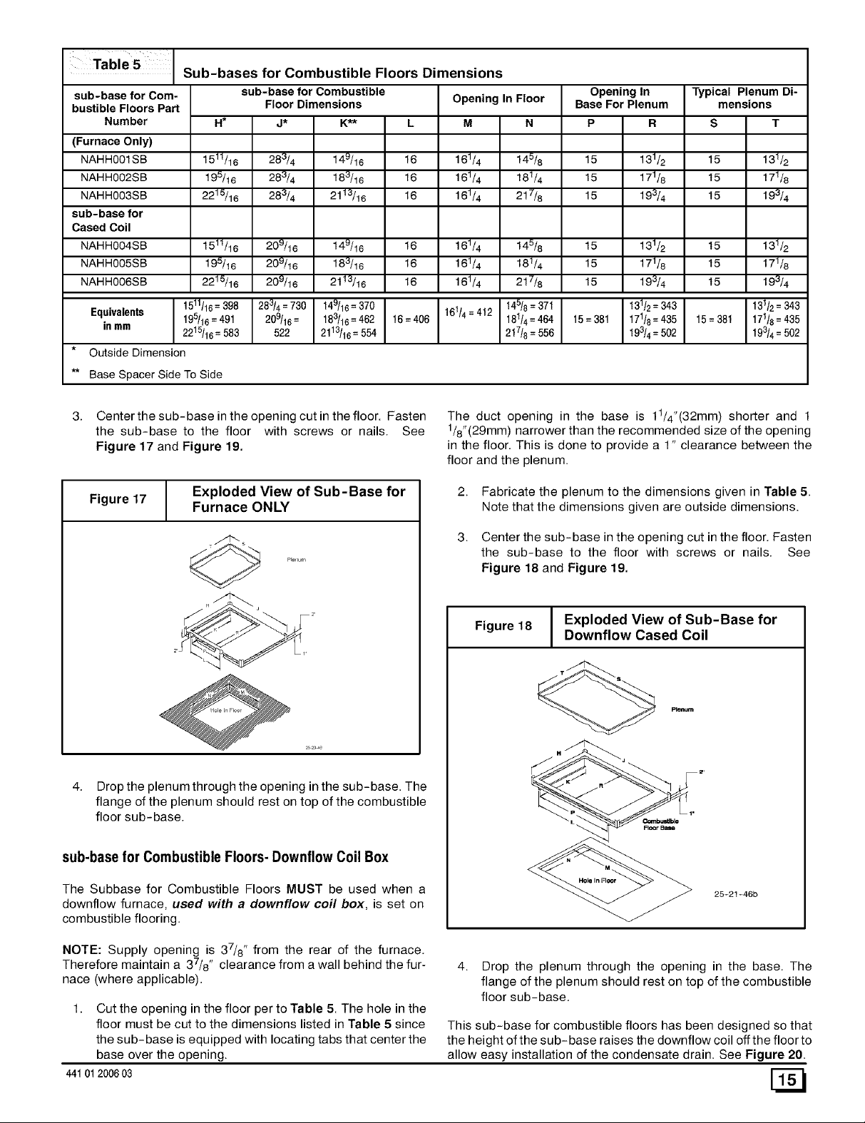
Table 5 Sub-bases for Combustible Floors Dimensions
sub-base for Com-
bustible Floors Part
Number
(Furnace Only)
NAHH001SB
NAHH002SB
NAHH003SB
sub-base for
Cased Coil
NAHH004SB
NAHH005SB
NAHH006SB
Equivalents
in mm
Outside Dimension
Base Spacer Side To Side
1511/16= 398
19_16=491
221_16 = 583
sub-base for Combustible
Floor Dimensions
H*
1511/16
195/16
2215/16
1511/16
195/16
2215/16
j* K_-,_
283/4 149/16
283/4 183/16
283/4 2t13/16
209/16 149/16
209/16 183/16
209/16 2t13/16
283/4 = 730 149/16= 370
209/16= 183/16= 462
522 2113/16= 554
Opening In Floor
L
16
16
16
16 161_
16 161_
16 161_
16=406 161/4=412
M N
161/4 145/8
161/4 181/4
161/4 217/8
145/8
181/4
217/8
145/8= 37t
181/4=464
217/8=556
Opening ln
Base For Plenum
P R
15 131_
15 171_
15 193/4
15 131_
15 171_
15 193/4
15=381 171/8=435
131/2=343 I
19_4= 502
Typical Plenum Di-
mensions
S T
t5 131_
t5 171/8
t5 19_4
t5 131_
t5 171/8
t5 19_4
t5=381 171/8=435
131/2=343
193/4=502
Center the sub-base in the opening cut in the floor. Fasten
the sub-base to the floor with screws or nails. See
Figure 17 and Figure 19.
Exploded View of Sub-Base for
Figure 17 Furnace ONLY
4. Drop the plenum through the opening in the sub-base. The
flange of the plenum should rest on top of the combustible
floor sub-base.
The duct opening in the base is 11/4"(32mm) shorter and 1
1/8"(29mm ) narrower than the recommended size of the opening
in the floor. This is done to provide a 1" clearance between the
floor and the plenum.
2,
Fabricate the plenum to the dimensions given in Table 5.
Note that the dimensions given are outside dimensions.
3,
Center the sub-base in the opening cut in the floor. Fasten
the sub-base to the floor with screws or nails. See
Figure 18 and Figure 19.
Figure 18 Downflow Cased Coil
Exploded View of Sub-Base for
sub-base for Combustible Floors- Downflow Coil Box
The Subbase for Combustible Floors MUST be used when a
downflow furnace, used with a downflow coil box, is set on
combustible flooring.
NOTE: Supply opening is 37/8" from the rear of the furnace.
Therefore maintain a 37/8', clearance from a wall behind the fur-
nace (where applicable).
1. Cut the opening in the floor per to Table 5. The hole in the
floor must be cut to the dimensions listed in Table 5 since
the sub-base is equipped with locating tabs that center the
base over the opening.
44101200603
25-21-46b
4. Drop the plenum through the opening in the base. The
flange of the plenum should rest on top of the combustible
floor sub-base.
This sub-base for combustible floors has been designed so that
the height of the sub-base raises the downflow coil offthe floor to
allow easy installation of the condensate drain. See Figure 20.
Page 16

Figure 19
sub-base
Insulation
Setting the Base
Furnace
Figure21 Filter Rack Installation
Wood Floor
25-21-05C
Non-Combustible Floor:
Set the furnace over the opening in the floor. If necessary, grout
around the base to seal air leaks between the base and the floor.
Figure 20 Condensate Line Raised by Base
25-20-52
1. Insert end of filter rack with 3/4" (19mm) flange into slot in
the back of the unit. See Figure 21.
2. With filter rack pushed back, insert front end with 1/4"
(6mm) flange into position and push into front slot. with filter
rack pushed as far forward as it will go, bend 1/4"(6mm)
flange and 3/4"(19mm ) flange up 90 degrees. See
Figure 21.
NOTE: Plenum must be fitted as close to the return air flange of
the unit as possible to eliminate any air bypassing the filters.
3. Filters can only be installed through the right hand side of
the unit blower opening. Slide filter into unit until it is in posi-
tion to be pushed up and over into place on the left hand
side of unit. See Figure 22.
4. Slide remaining filter into unit and up into place on right
hand side of unit. See Figure 22.
Figure 22 Filter Installation
f
A = 14"1350mm )
Filters:
The filters supplied with the furnace may be installed in the return
air plenum above the furnace. A filter rack is supplied with each
furnace. See Figure 21 and Figure 22.
NOTE: The return air plenum MUST extend a sufficient height
above dimension "A" (Figure 22) to provide for the attachment of
a return air duct or grille above the filters.
_] 44t 012006 03
25-21-05d
Page 17

9. ChecksandAdjustments
Startup
NOTE: Refer to startup procedures in the Users Information
Manual.
CAUTION
If any sparks, odors or unusual noises occur, immedi-
ately shut OFF power to furnace. Check for wiring er-
rors or obstruction to blower.
Gas Supply Pressure
Gas supply pressure should be within rninimum and rnaxirnum
values listed on rating plate. Pressures are usually set by gas sup-
pliers.
(See LP. Kit instruction manual for furnaces converted to LP.
gas)
ManifoldGas Pressure Adjustment
The low fire input rating of the furnace is 70% of the high fire input
rating that is shown on the furnace rating plate for operation at alti-
tudes up to 2,000'. The low fire/high fire regulator adjusting
screws are located on top of the valve and are marked LO and HI.
A small slotted blade screwdriver can be used to adjust the regu-
lators. Replace the regulator caps on the gas valve when the ad-
justments are complete.
The Honeywell SV][][gas valve is constructed with an ON/OFF
slide switch on top of the plastic housing. For furnace operation,
the slide switch must be in the ON position. For trouble shooting,
the gas valve is equipped with a green status light on top of the
plastic housing. (See Section 11. Sequence of Operation &
Diagnostics)
NOTE: Make adjustment to manifold pressure with burners oper-
ating.
screw counterclockwise to increase or clockwise to decrease
flame as required. Replace cap after adjusting screw.
iiiiiiiiiiiiiiiiiiiiiiiiiiiiiiiiiiiiiiiiiiiiiiiiiiiiiiiiiiiiiiiiiiiiiiiiii,_
Proper Flame _ /
Adjustment /_
Pilot Burner
/_ Flame Rod
_ / "_"_ Hot Surface
10-11-65
Main Burner Flame Check
Allow the furnace to run approximately 10 minutes then inspect
the main burner and pilot flames. See Figure 24.
Check for the following (Figure 24):
• Stable and blue flames. Dust may cause orange tips or
wisps of yellow, but flames MUST NOT have solid, yel-
low tips.
• Flames extending directly from burner into heat ex-
changer.
• Flames do NOT touch sides of heat exchanger
Ifany problems with main burner flames are noted, it may be nec-
essary to adjust gas pressures, or check for drafts.
Main Burner
Fire or explosion hazard.
Turn OFF gas at shut off before connecting U-
tube manometer.
Failure to turn OFF gas at shut off before con-
necting U-tube manometer can result in death
and/or personal injury.
1.
With gas OFF, Connect manometer to gas valve or maniflod
tap. Use manometer with a 0 to rain. 12" water column range.
2.
Turn gas ON and remove adjustment screw cover on gas
valve. Turn counterclockwise to decrease pressure and
clockwise to increase.
NOTE: Adjustment screw cover MUST be placed on gas valve
before reading manifold pressure and operating furnace.
3. For altitudes up to 2000', set pressure to value shown in
Table 3. For altitudes between 2000' to 8000', see Section
5. "Gas Supply and Piping" for correct pressure value.
Adjust PilotBurner
The furnace has a pilot flarne to light the rnain burner. The flame
should surround 3/8" to 1/2" of the flame rod. See Figure 23. To
adjust, remove cap from pilot adjusting screw on gas valve. Turn
44101 2006 03
Burner Face
10-10-78
Temperature Rise Check
The blower speed MUST be set to give the correct air temperature
rise through the furnace as marked on the rating plate. Tempera-
ture rise is the difference between supply and return air tempera-
tures.
To check temperature rise,use the following procedure:
1. Place thermometers in supply and return air registers as
close to furnace as possible, avoiding direct radiant heat
from heat exchangers.
2. Operate furnace on high fire for 10 minutes with all the reg-
isters and duct dampers open by using a jumper wire on R
to Wl and W2 thermostat connections on the fan board.
3. Take readings and compare with range specified on rating
plate.
Page 18

4. Ifthetemperatureriseisnotinthecorrectrange,theblower 2.
speedmustbechanged.Ahigherblowerspeedwilllower
thetemperaturerise.A lowerblowerspeedwillincrease
thetemperaturerise.
5. Repeatsteps2thru4withthefurnaceoperatingonIowfire
for10minutesbyusingajumperwireontheRtoW1ther-
mostatconnectionsonthefanboard.
6. Removethejumperwireaftertheadjustmentsarecom- 3.
plete.
ChangingBlower Speed
Electrical shock hazard.
Turn OFF power to furnace before changing speed
taps.
Failure to do so can result in death, personal injury
and/or property damage.
Since the manufacturer cannot establish the static pressure
that will be applied to the unit, it is the responsibility of the
installer dealer/contractor to select the proper speed taps for
the application when the unit is installed.
Change the heat or cool blower motor speed by removing the
motor lead from the "Heat" or "Cool" terminal and replace it
with the desired motor speed lead from the "Unused Motor
Lead" location. Connect the wire previously removed from
the "Heat" or "Cool" terminal to the vacated "Unused Motor
Lead" terminal.
Ifthe same speed must be used for both heating and cooling,
remove the undesired motor speed lead from the "Heat" or
"Cool" terminal and connect that lead to the open terminal at
"Unused Motor Lead" location or tape off. Attach a jumper
between the "Heat" and "Cool" terminals and the remaining
motor speed lead.
Note: When using the same speed on motors with (4) speed
leads, it will be necessary to tape off the terminal of the motor
speed lead removed from the "Heat" or "Cool" terminal with
electrical tape since an open terminal will not be available at
the "Unused Motor Lead" location.
Continuous Fan Operation
A terminal is provided on the electronic fan control located in the
circulating blower compartment for operation of the continuous
fan option. This connection is intended for the low speed motor
tap, and has a lower contact rating (8 amps) than the heat and
cool taps. When the low speed blower lead is connected to this
terminal, this will provide low speed blower operation whenever
the other two speeds (Heat or Cool) are not energized.
If it is necessary to change speeds, refer to steps below.
Refer to Furnace Wiring Diagram for location of the heating
and cooling speed taps located on the electronic fan control
as well as location of unused blower motor speed leads. Use
the chart (Table 6) to determine the blower motor speed set-
tings.
Table 6
Wire Color
Orange*
* Med-High speed may not be provided on all models.
Black
Blue
Red
Blower Speed Chart
Motor Speed
High
Med-High
Medium
Low
10.FurnaceMaintenance
CAUTION
It is recommended that the furnace be inspected and
serviced on an annual basis (before the heating sea-
son) by a qualified service technician.
Thoroughly check the system after modification to ensure the
proper operation of the circulating air blower in all modes of op-
eration.
Separate speed selectionsfor Heat, Cool, and Continuous
Fan
Connect low speed lead from circulating motor to the "Cont" ter-
minal at the electronic fan control. The appropriate motor leads
should already be connected to the "Heat" and "Cool" terminals.
Heating andContinuous Blower Speed the Same
If it is necessary to operate the heating speed and continuous
blower speed using the same blower speed, connect a jumper be-
tween the "Heat" and "Cont" terminals on the electronic fan con-
trol.
Note: There should be only ONE motor lead going to the "Heat"
and "Cont" terminals.
See "User's Information Manual".
_] 44t 012006 03
Page 19

11.SequenceofOperation& Diagnostics
The following is the normal operating sequence for the 2-stage control systern.
Cooling(Y) Request:
24 VAC signals applied to Y & G terminals of EFT (electronic fan tirner) control.
• Cool motor speed energized after 5 second Cool Fan On Delay time.
Y & G signals removed from EFT.
• Cool motor speed de-energized after 60 second Cool Fan Off Delay time.
Cooling (Y) and dehumidification (Y2) requests:
• 24 VAC signals applied to Y,Y2 & G terminals of EFT (electronic fan timer) control,
• Same operation as the cooling (Y) request, except the cooling speed is reduced 20% to compensate for high humidity conditions during
cooling operation. The cooling speed returns to the normal setting after the Y2 signal is removed.
CirculatingFan (G) Request:
24 VAC signals applied to G terrninals of EFT control.
• Low motor speed energized without delay.
G signal removed from EFT.
• Low motor speed de-energized without delay.
NOTE1) Furnaces with DC blower motors run a low circulating fan speed in response to G request.
NOTE2) Furnaces with PSC blower motors de-energize the Low Heat fan speed during the heat exchanger warm-up period on a
call for Heating that occurs during a G request.
NOTE3) Heating or Cooling requests received during a Fan request cause the fan speed to change to the appropriate heat or cool
speed after the selected Fan On Delay time expires. The fan returns to circulating speed after the selected Fan Off Delay time expires
following loss of the Heating or Cooling request.
HeatingRequest (two stagethermostat operation):
24 VAC signal applied to Wl terminal of EFT control.
• Inducer motor turns on at high speed.
• The high fire solenoid energizes.
• Following a 3 second prepurge delay, the pilot valve opens and the ignitor begins to warm up.
• After the pilot lights, the main burners energize and light (burners now at high fire rate).
• Timed from the opening of the main gas valve, the control will delay the selected Heat Fan On Delay time before switching the
inducer to low speed, de-energizing the high fire solenoid and the fan switches to Low Heat speed.
24 VAC signals applied to W1 and W2 terminals of EFT control.
• Same light-off routine as described above except that at the end of the selected Heat Fan On Delay, the inducer remains on high
fire, the high fire solenoid remains energized and the High Heat fan speed energizes.
W1 and W2 signals removed from EFT.
• The gas valve de-energizes and the main burners go out.
• The inducer runs at its present speed for a 5 second postpurge period.
• The fan switches to (or stays at) Low Heat speed.
• Timed from the gas valve de-energizing, the Low Heat fan speed de-energizes after the selected Heat Fan Delay time expires.
NOTE4) If a new Heating request arrives while the control is waiting inthe Heat Fan Off Delay time, the fan speed switches to High
Heat until the Heat Fan Off Delay expires or the Heat Fan On Delay expires for the new Heating request.
NOTE5) The EFT control responds without delay to the presence or loss of W2 (with W1 constant). W1 &W2 results in high inducer,
high fire and High Heat fan speed. W1 only results in low inducer, low fire and Low Heat fan speed.
HeatingRequest withGas Supply Line Shut Off:
24 VAC signals applied to Wl terminal of EFT control.
• Inducer motor turns on at high speed.
• The high fire solenoid energizes.
• Following a 3 second prepurge delay, the pilot valve opens and the ignitor begins to warm up.
• The ignitor glows red-hot for 30 seconds, then turns off.
• The igniter stays off for 25 seconds, then begins to warm-up again.
• The igniter glows red-hot for 30 seconds, then turns off.
• The pilot valve closes 3 seconds after the igniter de-energizes.
44101200603
Page 20

• The inducer de-energizes 5 seconds after the pilot valve closes.
• The SmartValve proceeds to soft lockout and flashes error code 6.
• The control exits soft lockout after 5 minutes and begins another ignition sequence.
GasValve DiagnosticCodes (See Figure 25)
Steady Flash = Normal Operation
2 Flashes
3 Flashes
4 Flashes
5 Flashes
6 Flashes
8 Flashes
9 Flashes
= Low Pressure Switch Stuck Closed
: Low Pressure Switch Stuck Open or
Manual ON/OFF Switch in OFF Position or
Aux. Limit Switch Open
= Limit Switch Open
= Flame Sensed Out of Sequence
= Control in Soft Lockout (Automatic Restart or Retry Delay)
= High Pressure Switch Stuck Closed
= High Pressure Switch Stuck Open
Figure 25
On/Off
INLET
Typical Gas Valve Honeywell
1
Diagnostic Light
(onsome models)
Pilot
OUTLET
25-22-25a
_] 44t 012006 03
 Loading...