

Page 1
Installation Instructions
SINGLEPACKAGEHEATPUMPS
PHF & HPFM Series - 2 to 5 TON
Printed in U.S.A.
518 01 1101 01 4-25-99
LP1
Page 2
Safety Labeling and Signal Words
Danger,Warning and Caution
The signal words DANGER, WARNING and CAUTION are
used to identify levels of hazard seriousness. The signal
word DANGER is only used on product labels to signify an
immediate hazard. The signal words WARNING and
CAUTION will be used on product labels and throughout
this manual and other manuals that may apply to the
product.
Signal Words
DANGER - Immediate hazards which WILL result in
severe personal injury or death.
WARNING - Hazards or unsafe practices which COULD
result in severe personal injury or death.
CAUTION - Hazards or unsafe practices which COULD
result in minor personal injury or product or property
damage.
Signal Words in Manuals
The signal word WARNING is used throughout this manual
in the following manner:
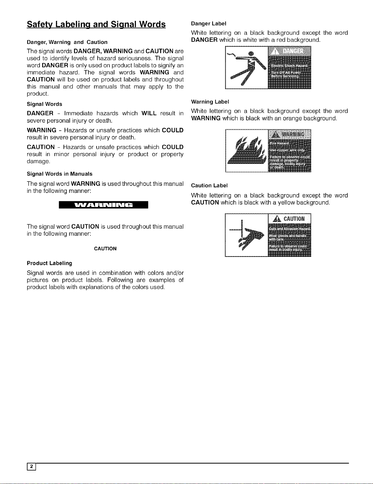
Danger Label
White lettering on a black background except the word
DANGER which is white with a red background.
Warning Label
White lettering on a black background except the word
WARNING which is black with an orange background.
Caution Label
White lettering on a black background except the word
CAUTION which is black with a yellow background.
The signal word CAUTION is used throughout this manual
in the following manner:
CAUTION
Product Labeling
Signal words are used in combination with colors and/or
pictures on product labels. Following are examples of
product labels with explanations of the colors used.
Page 3
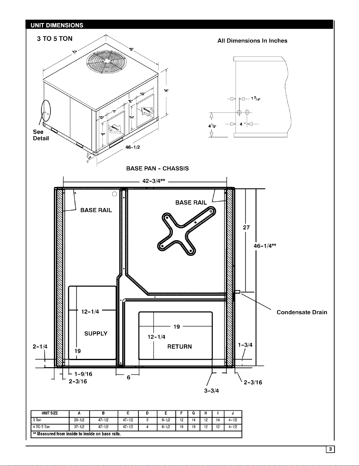
3 TO 5 TON All Dimensions In Inches
Detail
46-1/2
BASE PAN - CHASSIS
42 -3/4"*
©
BASE RAIL
-- 12-1/4
___ 19
I
1-9/16
2-3/16
SUPPLY
I
27
46- /4"*
Condensate Drain
1-3/4
/
2- 3/16
3-3/4
UNITSIZE A B C
3 Ton 29-1/2 47-1/2 47-1/2
4 TO5Ton 37-1/2 47-1/2 47-1/2
** Measured from inside to inside on base rails.
D
3
4
E F G H I J
9-1/2 12 14 12 14 4-1/2
6-1/2 19 19 12 12 4-1/2
131
Page 4
SAFE INSTALLATION
Installation or repairs made by unqualified persons can result
in hazards to you and others. Installation MUST conform with
local building codes or, in the absence of local codes, with the
ANSI Z223.1 and the National Electrical Code NFPA70-f 990 or
in Canada the National Standard CANiCGA B149-f and CSA
C.22.1 - Canadian Electrical Code Part 1.
The information contained in this manual is intended for use
by a qualified service technician familiar with safety proce-
dures and equipped with the proper tools and test instru-
ments.
Failure to carefully read and follow all instructions in this
manual can result in furnace malfunction, property damage,
personal injury and/or death.
• Seal supply and return air ducts.
• Check to see that filters are installed correctly and are
the proper type an size.
NOTE: It is the personal responsibility and obligation of the
customer to contact a qualified installer to ensure that the
installation is adequate and conforms to governing codes
and ordinances.
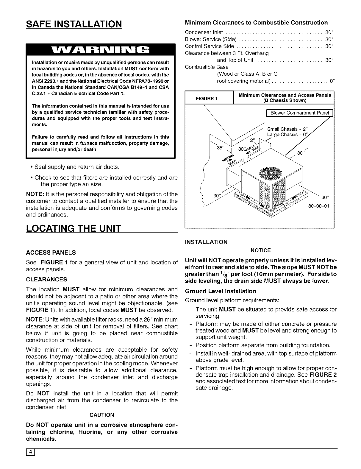
Minimum Clearances to Combustible Construction
Condenser Inlet .................................... 30"
Blower Service (Side) ............................... 30"
Control Service Side ................................ 30"
Clearance between 3 Ft. Overhang
and Top of Unit ........................ 30"
Combustible Base
(Wood or Class A, B or C
roof covering material) ..................... 0"
FIGURE 1
J Minimum Clearances and Access Panels
(B ChassisShown)
I Blower Compartment Panel
Small Chassis - 2"
Large Chassis
LOCATING THE UNIT
ACCESS PANELS
See FIGURE 1 for a general view of unit and location of
access panels.
CLEARANCES
The location MUST allow for minimum clearances and
should not be adjacent to a patio or other area where the
unit's operating sound level might be objectionable. (see
FIGURE 1). In addition, local codes MUST be observed.
NOTE: Units with available filter racks, need a26" minimum
clearance at side of unit for removal of filters. See chart
below if unit is going to be placed near combustible
construction or materials.
While minimum clearances are acceptable for safety
reasons, they may not allow adequate air circulation around
the unit for proper operation inthe cooling mode. Whenever
possible, it is desirable to allow additional clearance,
especially around the condenser inlet and discharge
openings.
Do NOT install the unit in a location that will permit
discharged air from the condenser to recirculate to the
condenser inlet.
CAUTION
INSTALLATION
NOTICE
Unit will NOT operate properly unless it is installed lev-
el front to rear and side to side. The slope MUST NOT be
greater than 1/8"per foot (10mm per meter). For side to
side leveling, the drain side MUST always be lower.
Ground Level Installation
Ground level platform requirements:
- The unit MUST be situated to provide safe access for
servicing.
- Platform may be made of either concrete or pressure
treated wood and MUST be level and strong enough to
support unit weight.
- Position platform separate from building foundation.
- Install in well-drained area, with top surface of platform
above grade level.
- Platform must be high enough to allow for proper con-
densate trap installation and drainage. See FIGURE 2
and associated text for more information about conden-
sate drainage.
DO NOT operate unit in a corrosive atmosphere con-
taining chlorine, fluorine, or any other corrosive
chemicals.
141
Page 5
Rooftop Installation
Rooftop platform requirements:
- The unit MUST be situated to provide safe access for
servicing.
- The existing roof structure MUST be adequate to sup-
port the weight of the unit or the roof MUST be
reinforced.
Check the weight of the unit in relation to the roof struc-
ture and local building codes or ordinances and
reinforce roof structure if necessary. See the last page
of this manual for unit weights.
- Support for the unit MUST be level and strong enough
to carry unit weight. The support may consist of a plat-
form or a combination of platform and roof beams or
curb.
- See Hoisting section for hoisting instructions.
HOISTING
NOTE: All access panels MUST be secured in place before
hoisting.
The unit should be hoisted with two lifting slings. Attach the
slings to rigging shackles that have been hooked through
holes in the base rail.
Two spreader bars MUST be placed on top of the unit to
protect the unit from damage from the pressure exerted by
the slings. Make sure that all equipment is adequate to
handle the weight of the unit and that the slings will not allow
the unit to shift.
Refer to on the back cover of this manual for illustrated
rigging instructions and weight chart.
DOWNFLOW CONVERSION
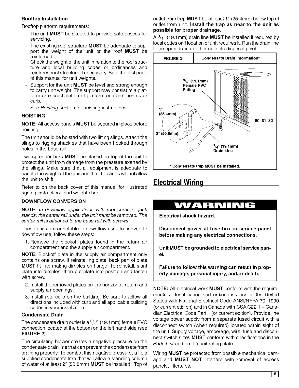
outlet from trap MUST be at least 1" (25.4mm) below top of
outlet from unit. Install the trap as near to the unit as
possible for proper drainage.
A 3/4" (19.1mm) drain line MUST be installed if required by
local codes or if location of unit requires it. Run the drain line
to an open drain or other suitable disposal point.
FIGURE 2
I N
(25.4mm)
2" (50.8mm)
* Condensate trap MUST be installed.
/ Condensate Drain Information*
1
3/4" (19.1mm)
Female PVC
Fitting
80-31-32
3/4" (19.1mm)
Drain Line
ElectricalWiring
NOTE: In downflow applications with roof curbs or jack
stands, the center rail under the un# must be removed. The
center rail is attached to the base rail with screws.
These units are adaptable to downflow use. To convert to
downflow use, follow these steps:
1. Remove the blockoff plates found in the return air
compartment and the supply air compartment.
NOTE: Blockoff plate in the supply air compartment only
contains one screw. If reinstalling plate, back part of plate
MUST fit into mating dimples on flange. To reinstall, slant
plate into dimples, then put plate into position and fasten
with screw.
2. Install the removed plates on the horizontal return and
supply air openings.
3. Install roof curb on the building. Be sure to follow all
directions included with curb and all applicable building
codes in your installation.
Condensate Drain
The condensate drain outlet is a 3/4" (19.1 mm) female PVC
connection located at the bottom on the left hand side (see
FIGURE 2).
The circulating blower creates a negative pressure on the
condensate drain line that can prevent the condensate from
draining properly. To combat this negative pressure, a field
supplied condensate trap that will allow a standing column
of water of at least 2" (50.8mm) MUST be installed. Top of
Electrical shock hazard.
Disconnect power at fuse box or service panel
before making any electrical connections.
Unit MUST be grounded to electrical service pan-
el.
Failure to follow this warning can result in prop-
erty damage, personal injury, and/or death.
NOTE: All electrical work MUST conform with the require-
ments of local codes and ordinances and in the United
States with National Electrical Code ANSI/NFPA 70-1990
(or current edition) and in Canada with CSA C22.1 - Cana-
dian Electrical Code Part 1 (or current edition). Provide line
voltage power supply from a separate fused circuit with a
disconnect switch (when required) located within sight of
the unit. Supply voltage, amperage, wire, fuse and discon-
nect switch sizes MUST conform with specifications in the
Parts List and on the unit rating plate.
Wiring MUST be protected from possible mechanical dam-
age and MUST NOT interfere with removal of access
panels, filters, etc.
151
Page 6

All exposed wiring and connections MUST be made with
weatherproof cable or wire unless installed in conduit.
LowVoltageWiring
Low voltage connections are made on the electronic control
board inside the electrical control compartment (see
FIGURE 5). For access, remove the electrical control ac-
cess panel).
Refer to the Parts List for the connection wiring diagram for
the applicable model and to the instructions included with
the thermostat.
Route low voltage wires through the port located at the bot-
tom left corner of the blower access panel side of the unit.
Route low voltage wires behind unit cornerpost, through the
wire clip provided, and up to the low voltage terminal board.
NOTE: If an Electric Heat Accessory is installed, see the
Electric Heat Accessory Installation Manual for low voltage
connections.
Thermostat
FIGURE 4 Connection Diagram
I ElectronicThermostat Low Voltage
Electronic Thermostat Subbase
- (White Rodgers: 1F92-71 and 1F94-71)
P -- - "1 f - -- "1
(2) ' (3) '
I I
, , , , (1)1
[C] [G] [R] [O] [Y1] [Wl] [W2] [El]
I I
i i
,, ,,r--
1 I 1 I 1 11 I
..... [¢ [¢
[C] [G] [R] [O1 [Y1] 1] 2]
Corn Fan 24V Rev. Pump Aux.
Valve Heat Emer.
Energ Cool Heat
Cool
Low Voltage Connections on Control Board.
Thermostat Subbase Notes:
(1) Common [C] may be shown as [B] or IX] on other types
of thermostats.
(2) Jumper subbase terminals [Y1] and [Wl].
(3) Jumper subbase terminals [W2] and [El].
, ,i Jumper Wire
i
I
The location ofthe thermostat has an important effect on the
operation of the unit. FIGURE 3 and FIGURE 4 show typi-
cal wiring connections for both manual and electronic
thermostats. FOLLOW THE INSTRUCTIONS INCLUDED
WITH THE THERMOSTAT FOR CORRECT LOCATION,
MOUNTING AND WIRING .
FIGURE 3 I Mechnical Thermostat Low Voltage
Connection Diagram
1
Mechanical Thermostat Subbase
- (White Rodgers: 1F58-34)
f - -- "1
(2) '
!
' ' (1)
[C] [G] [R] [O] [Y] [W2] [E]
Jumper Wire
[C] [G] [R] [O] [Y1] [Wl] [W2]
Corn Fan 24V Rev. Pump Aux.
Valve Heat Emer.
Ener Coo! Heat
Cool
Low Voltage Terminal Board at the Unit.
Thermostat Subbase Notes:
(1) Terminals [W2] and [E] already jumpered at subbase.
GroundConnections
A ground lug is installed on the control plate for the ground
connection (see FIGURE 5). Use a copper conductor of the
appropriate size from the unit to a grounded connection in
the electrical service panel or to a properly driven and elec-
trically grounded ground rod. See warning above.
LineVoltageWiring
Do NOT complete line voltage connections until unit is per-
manently grounded. All line voltage connections and the
ground connection MUST be made with copper wire.
Connections for line voltage are made on the unit electrical
control plate (see FIGURE 5). For access, remove the elec-
trical access panel.
Refer to applicable wiring diagram in the Parts List. Com-
plete the line service connections to the contactor 'U
terminals on the electrical control plate. Check all screwter-
minals to ensure they are tight.
NOTE: If an Electric Heat Accessory is installed, refer to the
Electric Heat Accessory Installation Manual to determine
line voltage connections. The Electric Heat Accessory
mounts inside the unit. Field supplied line voltage wires for
the Electric Heat Accessory (separate from the field sup-
plied line voltage wires to the unit) connect to the circuit
breaker(s) in the Electric Heat Accessory.
161
Page 7

Converting 230V Units to 208V
To convert 230V units to 208V:
and located, MUST NOT exceed the temperature limita-
tions for type T wire and MUST be installed according to the
manufacturer's instructions for the devices.
1. Turn electric power OFF.
2. Remove the electrical access panel.
3. Locate the 24V control transformer.
4. Remove wires from the terminal labeled "240V" onthe
24V control transformer and reconnect them to the
208V terminal of the 24V control transformer.
5. Replace the electrical access panel.
FieldInstalled Equipment
Wiring to be done in the field between the unit and other de-
vices, or between separate devices which are field installed
FIGURE 5 Typical Wiring Installation
FinalElectricalCheck
Make a final wiring check to be sure system is correctly
wired. Inspect field installed wiring and the routing to ensure
that rubbing or chafing due to vibration will not occur.
NOTE: Wiring MUST be installed so it is protected from pos-
sible mechanical damage.
t©
,ml
Control -_
Board
/ l _ _..._ "_
/
LT°Wrt.Vn°'_age [_ / ___ .._
Connections _"_ " _
, , ' " "_ Contactor
Transfo_
RI o w,lw_ GIo
Ground lug
171
Page 8

AirDistributionSystem
For airflow data (blower performance data, blower speed
tap settings, etc.) see the Parts List.
Ductwork
NOTE: The total heat gain/heat loss from the structure as
expressed in total Btu/hr MUST be calculated by manufac-
turer's method or in accordance with "A.S.H.R.A.E. Guide"
or "Manual J - Load Calculations" published by the Air
Conditioning Contractors of America or in Canada"H.R.A.I.
Residential Heating and Cooling Load Calculation Manual."
The total heat gain calculated should be equal to or less
than the cooling capacity output based on D.O.E. test
procedures, steady state efficiency times input.
Ductwork, supply registers, and return air grilles MUST be
designed and sized to handle the unit's cooling air vol-
ume requirements. If the unit is connected to an existing
system, the ductwork MUST be checked to make sure it is
adequate. Extra runs or larger duct sizes may have to be
installed.
Maximum recommended velocity intrunk ducts is 1000 feet
per minute (5.08m/s). Velocity in branches should not ex-
ceed 800 feet per minute (4.06m/s). Refer to the Parts List
for unit air volume requirements and system sizing recom-
mendations.
DuctworkConnections
The use of flexible, non -combustible connectors between
main trunk ducts and supply and return air plenums is rec-
ommended to minimize vibration transmission.
NOTE: Connect supply and return air plenums to unit in a
manner that will allow the top of the unit to be removed with-
out removing plenums. Plenums MUST be individually
sealed to unit casing. Ducts MUST be terminated inside
structure.
Filters
All return air MUST pass through a filter before entering the
unit. An electronic air cleaner, optional filter racks or other
accessible filter arrangements MUST be installed in the re-
turn air ductwork. Minimum recommended filter areas are
based on a velocity of 300 ft/min (1.2m/s) for disposable fil-
ters and 500 ft/min (2.54m/s) for washable high velocity
filters.
CAUTION
Do NOT operate the unit without all filters in place.
NOTE: Ductwork sizing affects temperature rise and cool-
ing temperature differential. Be sure to properly size
ductwork to the capacity and airflow characteristics of your
unit. Failure to do so can affect limit controls, compressors,
motors, and other components and will lead to premature
failure ofcomponents. This will also adversely affect day to
day unit performance.
Refer to unit rating plate for proper Electric Heat Accessory
sizing and see the Temperature Rise Check section in the
Electric Heat Accessory Installation Instructions.
DuctworkInsulation
It is recommended that ductwork installed outdoors have a
minimum of 2" (51mm) of fiberglass insulation and be cov-
ered by a weatherproof vapor barrier that is protected
against damage. Caulking and flashings, or other means
adequate to provide a permanent weather seal, must be
used.
It is recommended that ductwork installed in attics or other
areas exposed to outdoor temperatures have a minimum of
2" (51mm) fiberglass insulation and have an indoor type va-
por barrier.
181
Page 9

Start-up Procedures
Electrical shock hazard.
Use extreme care during all of the following
checks and procedures.
Make sure electric power is turned OFF as
instructed in appropriate steps.
Cooling, Heating (Heat Pump) and Auxiliary Electric
Strip Heat
NOTE: The cooling, heat pump and strip heat airflows
are all on the same speed tap. The refrigerant system
requires the same specific CFM for proper operation in
the cooling and the heat pump mode. For this reason,
cooling and heating airflow must be the same. DO NOT
SPLITOUT INTO A COOLING SPEED AND HEATING
SPEED.
Failure to follow this warning can result in prop-
erty damage, personal injury, and/or death.
CirculatingAir Blower
DeterminingBlower Speed
1. Turn electric power OFF.
2.
From the system design, determine the external static
pressure (ESP) for the supply ducts, return ducts and
registers, diffusers, grilles, dampers, heaters and fil-
ters.
3. To your system ESP determined in Step 2, add 0.05
In. W.C. for a wet coil.
4. From the system design, determine the desired cool-
ing airflow in cubic feet per minute (CFM).
. Locate the unit's Blower Performance Data table in
the tech data sheet for the unit's voltage. (The tech
data sheet is attached to the inside of the electrical ac-
cess panel and is also published in the Parts List.)
From the table, determine the speed tap the desired
airflow requires.
6. See next section, Speed Taps, to set the blower motor
speed terminal block (speed taps) determined in the
following steps.
SpeedTaps
After determining the required CFM and speed tap data
from the tech data sheet, follow the steps below to change
speeds if necessary.
NOTE: The yellow lead MUST always be connected to the
speed tap block atthe common quick connect terminal. The
terminal is identified as COM. Also, this is the only lead
which is 3/16" wide. All other quick connects are 1/4" wide.
Refer to the unit's wiring diagram, which is attached to the
inside of the electrical access panel and is also published in
the Parts List for the desired speed tap to achieve the re-
quired CFM for the applicable model.
CheckBefore Starting
Check that the blower motor speed terminal block is
set to the proper speed. Refer to the unit wiring dia-
gram and the Technical Labels in the Parts List.
2.
Check to see that clean, properly sized field supplied
air filters are installed in the return air duct.
3.
Inspect the inside of the unit to be sure that all wires
are in place and all tools, etc. are removed.
4. Replace all service access panels.
Check the unit's operation as outlined in the following
instructions. If any unusual sparking, odors or noises are
encountered, shut OFF electric power immediately. Re-
check for wiring errors, or obstructions in or near blower
motors.
Sequenceof Operation
CoolingMode:Energized(R,G,O,Y1)
De-energized(N/A)
(a)When high and low voltage is initially applied to
unit:
(1) On a call for cooling ......... :
The compressor and condenser fan will have a delay
on and will energize after 5 minutes. The evaporator
blower motor will energize immediately. The delay on
for the compressor and the condenser fan can be by-
passed by jumpering the test pins on the defrost
board control.
(2) When the cooling setpoint has been satis-
fied ......... :
The compressor and condenser fan will de-energize
immediately. The evaporator blower motor will have a
delay off and will de-energize after 30 seconds.
(b) When high and low voltage has been applied
to unit for morethan 5 minutes:
(1) On a call for cooling ......... :
The compressor and condenser fan will energize im-
mediately. The evaporator blower motor energize
immediately.
Page 10

(2) When the cooling setpoint has been satis-
fied ......... :
The compressor and condenser fan will de-energize
immediately. The evaporator blower motor will have a
delay off and will de-energize after 30 seconds.
(2) When the heating setpoint has been satis-
fied ......... :
The compressor and condenser fan will de-energize
immediately. The evaporator blower motor will have a
delay off and will de-energize after 30 seconds.
HeatingMode:Energized(R,G,Y1)
De-energized(0)
(a)When high and low voltage is initially applied to
unit:
(1) On a call for heating ......... :
The compressor and condenser fan will have a delay
on and will energize after 5 minutes. The evaporator
blower motor will have a delay on and will energize af-
ter 30 seconds. The delay on for the compressor and
the condenser fan can be by-passed by jumpering
the test pins on the defrost board control.
(2) When the heating setpoint has been satis-
fied ......... :
The compressor and condenser fan will de-energize
immediately. The evaporator blower motor will have a
delay off and will de-energize after 30 seconds.
(b) When high and low voltage has been appliedto
unitfor morethan 5 minutes
(1) On a call for heating ......... :
The compressor and condenser fan will energize im-
mediately. The evaporator blower motor will have a
delay on and will energize after 30 seconds.
Defrost Mode:Energized (R,G,Y1) De-energized (0)
Defrost Sensor Closed
On a call for defrost .........
(1)
When the defrost sensor closes (this can be simu-
lated by placing a jumper across the DFST and
T'STAT terminals on the control board) in the heating
mode,there is a 30,60 or 90 minute defrost on delay
before the defrost mode begins. This delay is deter-
mined by the jumper selection on the control board.
See Figure 7.
(2)
When defrost has been completed .........
This condition will be maintained until the defrost sen-
sor opens or for a mzximum of 10 minutes, whichever
comes first.
The TEST selection will speed up the defrost/heating cycle
for diagnostic purposes. When the jumper is in the TEST
position and Y is energized, the unit will cycle from heating
(10 seconds) to defrost (2 seconds) to heating (10 seconds)
to defrost (2 seconds) for a maximum of 8 times. If the
jumper is left in the TEST position, the control will ignore the
call for TEST and default to a 90 minute defrost cycle. If the
jumper is not installed, the control will default to a 90 minute
defrost cycle.
NOTE: A jumper across the DFST and T'STAT terminals is
not necessary in order to check out the defrost control.
11ol
Page 11

FIGURE 6 I Blower Motor Speed Taps (3-Speed and 4-Speed Motors)
SPEED DATA IN UNITS
TECHNICAL INFORMATION LABEL
I BE SURE TO CHECK BLOWER MOTOR I
ON THE UNIT
Operation
Electrical shock hazard.
Turn OFF electric power supply at disconnect
switch or service panel before removing any ac-
cess or service panel from unit.
Failure to follow this warning can result in prop-
erty damage, personal injury, and/or death.
Features
ScrollAnti-CycleTimer
All single phase heat pumps with scroll compressors are
equipped with a defrost control board which features an in-
ternal anti-short cycle timer that delays the start of the
compressor in the event of a power interruption. This fea-
ture is to allow pressure equalization throughout the system
\-_\ /
and prevent possible reverse rotation of the scroll compres-
sor.
Lossof Charge PressureSwitch
A low pressure switch on the liquid line (high side) has been
installed to prevent system damage due to a loss of charge.
The switch will open and de-energize the contactor if the
high side pressure drops below the set point of the switch.
DefrostControlTime IntervalAdjustment
Electrical shock hazard.
Turn OFF electric power supply at disconnect
switch or service panel before removing any ac-
cess or service panel from unit.
Failure to follow this warning can result in prop-
erty damage, personal injury, and/or death.
illl
Page 12

To adjust defrost interval:
TurningThe Unit Off
1.
Turn off all power to Heat Pump.
2.
Remove control box cover.
3.
Locate electronic control board.
4.
The Control Board has a jumper that allows you to
change the defrost time interval. (See Figure Below)
Change the desired time by removing the jumper and
placing the jumper on 30, 60, or 90.
30 = 30 minutes, 60 = 60minutes, 90 = 90 minutes.
FIGURE 7 Defrost Control
C°2trrd°l
_ ]__ _ Jumper placed

Maintenance
Air Filters,CondenserCoil and Condensate
DrainMaintenance
Refer to Home Owners Manual supplied with your heat
pump for information on filter sizes, condenser coil clear-
ances from shrubbery and condensate drainage
allowances.
CAUTION
Do NOT operate unit without filters in place. Inspect fil-
ters monthly and clean and/or replace as needed.
RefrigerationAccess Ports
This unit is equipped with refrigeration access ports
mounted onthe side of the unit. Refer to FIGURE 9 for iden-
tification of ports.
This unit is also equipped with internal access ports on the
suction and discharge tubing line which can be used for
evacuation, pull down and recharging of the refrigeration
system.
FIGURE 9 Typical Access Ports
Oil the condenser fan motor after five years of operation and
every five years thereafter.
Use SAE 10W30 motor oil. To oil, remove the hole plugs from
the motor end bells and add several drops (approximately
1/2 teaspoonful) of oil with a squeeze type, flexible tube oil-
er. Replace hole plugs after oiling. Do NOT over oil.
Clean the surrounding area and the condenser and evapo-
rator coils. Use caution to avoid damage to coil fins. Do not
use an acid-based cleaner on coated fin material.
BlowerMotorAccess
To remove the blower motor and/or the blower motor hous-
ing assembly, remove the blower access panel.
Refer to FIGURE 10 for a view of blower motor and
compartment.
FIGURE 10 1 Blower Motor and Housing
AnnualMaintenanceand Inspection
CondenserFan Motor
CAUTION
Do NOT use 3 in 1oil, penetrating oil, WD40 or similar
oils to oil motor bearings.
BlowerWire Color Identification
Use FIGURE 11 to identify wires on blower motor.
To change speed tap settings, see Speed Taps in the Start-
up Procedures section of this manual.
1131
Page 14

FIGURE 11 Wire Colors
8@ @@ 16b
CirculatingAir Blower
Visually inspect the blower wheel for accumulations of dirt
or lint. Clean the compartment and the blower wheel. Ifac-
cumulation is excessive on blower wheel, or does not easily
remove, it will be necessary to remove the blower assembly.
CAUTION
Do NOT use 3 in 1oil, penetrating oil, WD40 or similar
oils to oil motor bearings.
Oil the blower motor by adding 1/2 teaspoonful (lcc) of SAE
10W30 to each motor bearing. The blower motor should be
oiled after five years of operation and every five years there-
after.
1141
 Loading...