

Page 1
Installation Instructions
I PGAA / PGAC / PGAD - 11/2 to 5 TON
PGMD/PGME
COMBINATIONUNITS
GASHEAT/ELECTRICCOOL
TABLEOFCONTENTS
1. SAFETY LABELING AND SIGNAL WORDS .................... 2
DANGER,WARNINGAND CAUTION ............................... 2
SIGNALWORDS ............................................... 2
SignalWordsinManuals........................................ 2
PRODUCTLABELING ........................................... 2
DangerLabel ................................................ 2
WarningLabel ............................................... 2
CautionLabel................................................ 2
2. UNIT DIMENSIONS ..................................... 3-4
3. SAFE INSTALLATION REQUIREMENTS ...................... 5
4. LOCATING THE UNIT .................................... 5
ACCESSPANELS .............................................. 5
CLEARANCES................................................. 5
MinimumClearancesto CombustibleConstruction...................... 5
GROUNDLEVEL INSTALLATION................................... 5
ROOFTOPINSTALLATION...................................... 5-6
HOISTING .................................................... 6
DownflowConversion........................................... 6
HeatingVentAssembly ......................................... 6
CondensateDrain ............................................. 6
5. PRE- EXISTING COMMON VENT CHECK ...................... 7
6. GAS SUPPLY AND PIPING ................................ 7
GASPIPING .................................................. 7
GasPipeSize ............................................... 7
PIPINGAT UNIT ................................................ 7
Connections................................................. 7
ORIFICES .................................................... 7
OrificeSizes ................................................. 7
ChangingOrifices ............................................. 8
7. ELECTRICAL WIRING .................................... 8
UneVoltageWiring ............................................ 8
GroundConnections ........................................... 8
UneConnections .............................................8
THERMOSTAT/HEAT ANTICIPATOR ...............................8
FinalElectricalCheck .......................................... 8
8. DUCTWORK ........................................... 8
DuctworkInsulation ........................................ 9
DuctworkConnections.......................................... 9
FILTERS ..................................................... 9
9. START- UP PROCEDURES ................................ 9
CHECKBEFORESTARTING ...................................... 9
ReverseRotation(ScrollCompressorsOnly) .......................... 9
ManifoldGas PressureAdjustment ................................. 9
GASPRESSURES.............................................. 9
CIRCULATINGAIRBLOWER ..................................... 10
HEATINGSTAR-UPPROCEDURES................................ 10
TemperatureRiseCheck ....................................... 10
FANCONTROLCHECK ......................................... 10
SPEEDTAPS ................................................. 11
CONTINUOUSFANOPERATION .................................. 11
COOLING ................................................... 11
10. OPERATION ......................................... 12
COMBUSTIONIINDOORFANCONTROL............................. 12
SCROLLANTI-CYCLETIMER .................................... 12
11. MAINTENANCE ....................................... 12
MONTHLYMAINTENANCEANDINSPECTIONCHECKS ................. 12
Air Filters .................................................. 12
HEATINGSEASONCHECKS (MONTHLY) ........................... 12
Pilot Flame ................................................. 12
MainBurnerFlame ........................................... 12
ANNUALMAINTENANCEANDINSPECTION ......................... "12
CondenserFan Motor ......................................... 12
VENTASSEMBLY ............................................. 13
BLOWERMOTORACCESS ...................................... 13
Method1 .................................................. 13
Motorremovalandreplacement.................................. 13
Method2 .................................................. 13
Burners/ HeatExchangers/ FlueGas Passages ...................... t3
INSPECTIONANDCLEANINGOF BURNERASSEMBLY
/HEATEXCHANGERS/FLUEGASPASSAGES..................... 13-14
ForOaaiifiedServiceTechnicianOnly ........................... t3-t4
12. RIGGING INSTRUCTIONS .............................. 15
13. NOTES ............................................. 16
462 01 1004 00
10-23-01
Printed in U.S.A.
Page 2
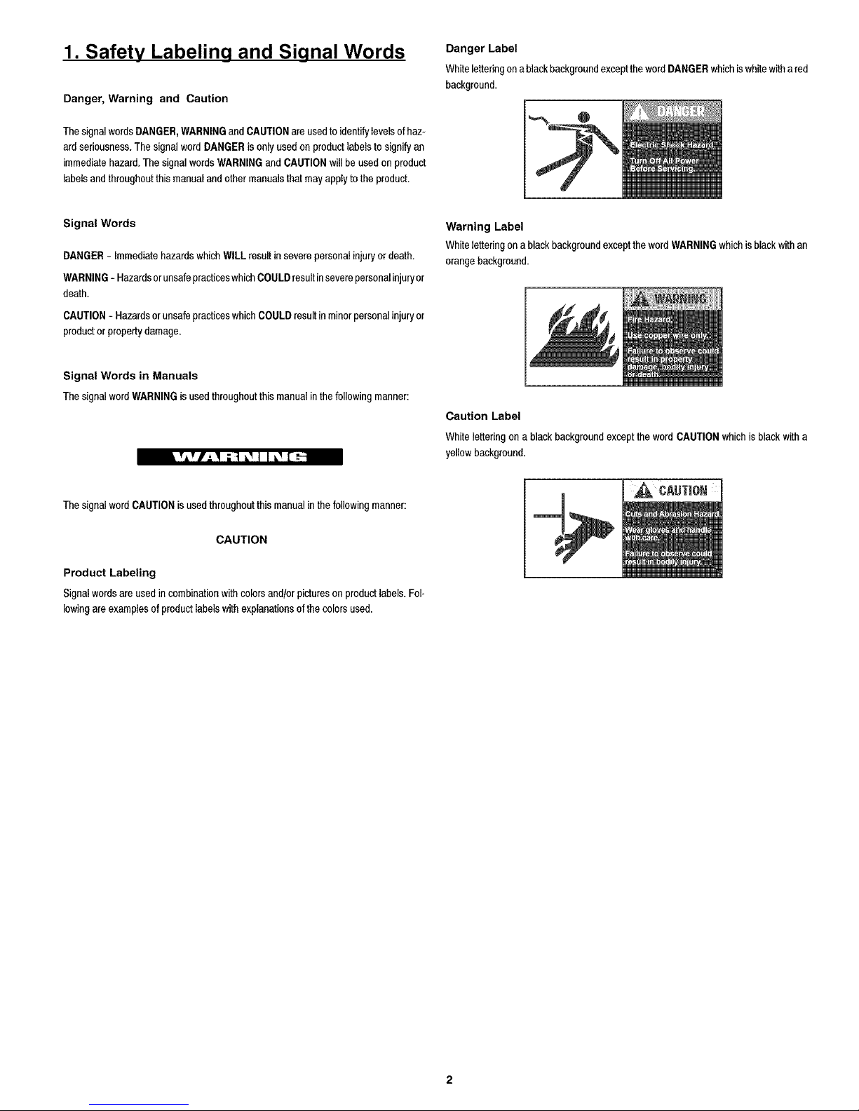
1. Safety Labeling and Signal Words
Danger, Warning and Caution
ThesignalwordsDANGER,WARNINGandCAUTIONareusedtoidentifylevelsofhaz-
ard seriousness.The signalword DANGERis onlyusedon productlabelsto signifyan
immediatehazard.The signalwordsWARNINGandCAUTIONwillbe used onproduct
labelsandthroughoutthis manualandothermanualsthat mayapplyto theproduct.
Danger Label
Whiteletteringonablackbackgroundexceptthe wordDANGERwhichiswhitewitha red
background.
Signal Words
DANGER- ImmediatehazardswhichWILLresultin severepersonalinjuryordeath.
WARNING- HazardsorunsafepracticeswhichCOULDresultinseverepersonalinjuryor
death.
CAUTION- HazardsorunsafepracticeswhichCOULDresultinminorpersonalinjuryor
productor propertydamage.
Warning Label
Whiteletteringon ablackbackgroundexceptthe wordWARNINGwhichisblackwithan
orangebackground.
Signal Words in Manuals
Thesignal wordWARNINGisusedthroughoutthismanualinthefollowingmanner:
Thesignal wordCAUTIONisusedthroughoutthismanualin thefollowingmanner:
CAUTION
Product Labeling
Signalwords areusedin combinationwithcolors and/orpictureson productlabels.Fol-
lowingareexamplesof productlabelswith explanationsofthe colors used.
Caution Label
Whiteletteringon a blackbackgroundexceptthe wordCAUTIONwhichisblackwitha
yellowbackground.
Page 3
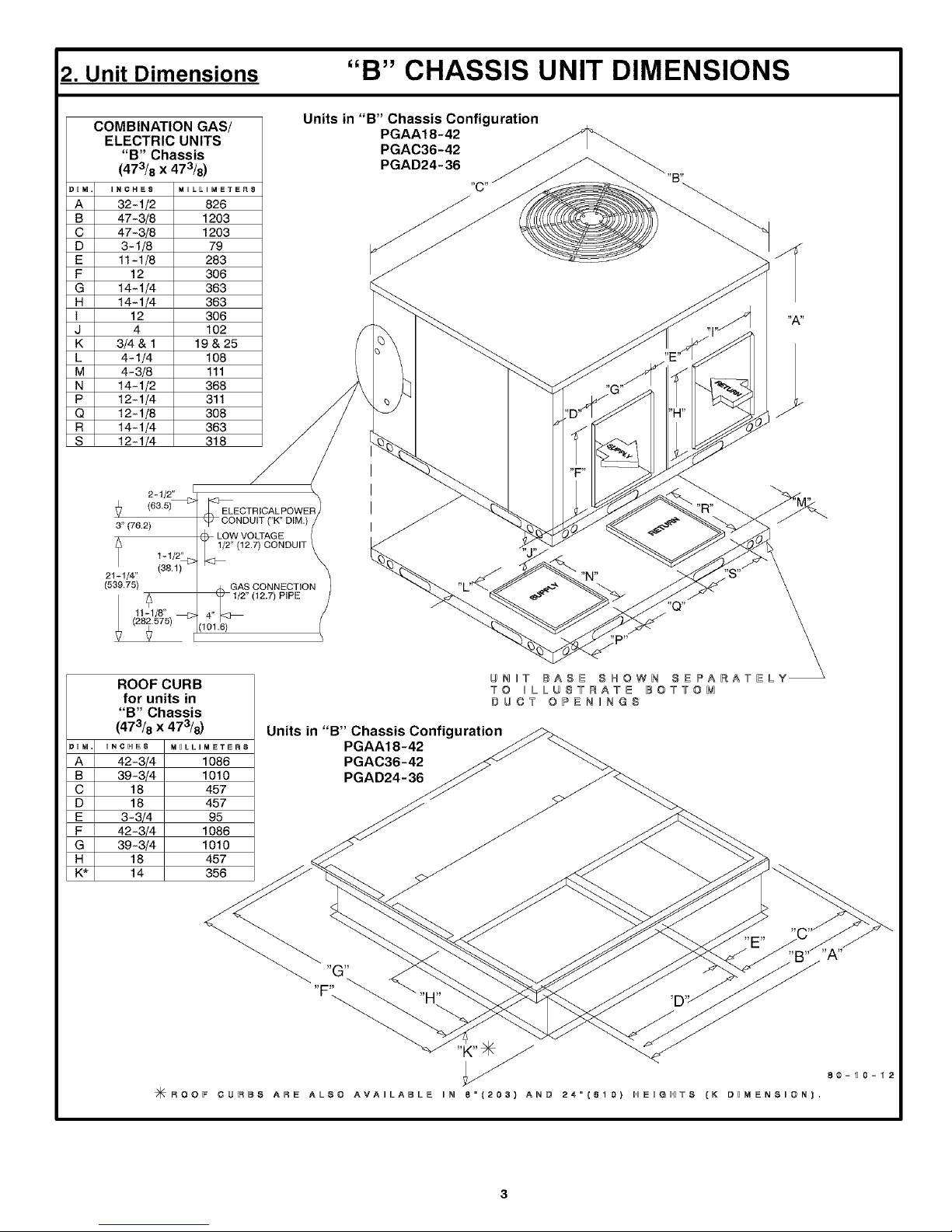
2. Unit Dimensions "B" CHASSIS UNIT DIMENSIONS
COMBINATION GAS/
A
B
C
D
E
F
G
H
I
J
K
L
M
N
P
Q
R
S
D01_<
A
B
C
D
E
F
G
H
K*
Units in "B" Chassis Configuration
PGAA18-42
ELECTRIC UNITS
"B" Chassis PGAC36-42 _ A
(473/8x473/8) PGAD24-36_ _ _ _"B"
INCHES MILLI_IETER "C" /__
32-1/2I 828
47-3/8 I 1203 / / (- _((_,(_..(_)_J))))))))]/ _. _.
47-378 I 1203 / / _ _._.___/JJJ _ "%1
3-1/8 I 79 / / ___/ _ /"
11-1/8 I 283 _ _ _/
12 I 306 _ //
14-1/4 I 363 _ //
14-1/4 I 363 _ //
12 I 306 __ _ _ "A"
4 102 'T'/"
4-1/4 to8 _ _ "E'_
12-1/4 311 // \_Xj _ _/'_ / _ -
12-118 308 / / 'D" // 'H" -"_/, /
14-1/4 363 / / y _ _O_
I
12-1/4 318
t&5)_> _._ _ ,,,
I-1/2'_
(539.75) _ } "",_ '_L"<,..,._ / _ _.. /_ \
11-1/8" _ 4"_
UNBT NAgN NHOWN 8NPARATNLY _
ROOFCURB TO ILLUSTRATE BOTTOM
for units in #UOT OPSN_I8
"B" Chassis
(473/8 x 473/8) Units in "B" Chassis Configuration_
"NCHES M,LI=IM_T_.8 PGAA18-42 _ _.
42-3/4 1086 PGAC36-42 _
3-3/4
42-3/4 1086 _ _ _ _
14 356
80-10-12
7_ROOF CU_E_S ARE ALSO AVA_LAE_LE I_ 8"(203} AND 24"(610) HEIGHTS (K D_MENSION).
Page 4
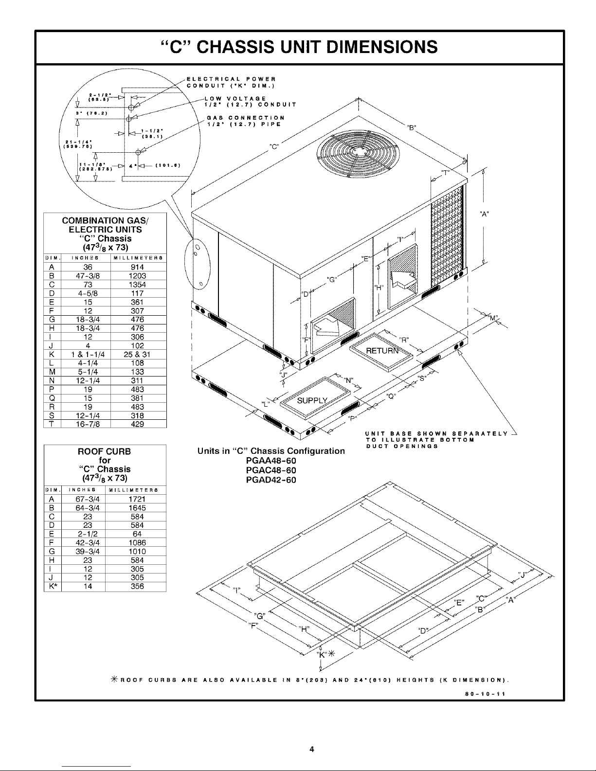
"C" CHASSIS UNIT DIMENSIONS
1-1/2"
COMBINATION GAS/
ELECTRIC UNITS
"C" Chassis
(473/8 X 73)
DgM. INCHES MILLIMETER8
A 36 914
B 47-3/8 t 203
C 73 1354
D 4-5/8 117
E 15 361
F 12 307
G 18-3/4 476
H 18-3/4 476
I 12 306
J 4 t02
K 1 & 1-1/4 25 & 31
L 4-1/4 108
M 5-1/4 133
N 12-1/4 311
P 19 483
Q 15 381
R 19 483
S 12-1/4 318
T 16-7/8 429
ROOF CURB
for
"C" Chassis
(473/8 X 73)
#_M. "NCHE8 M_LL_METER8
A 67-3/4 1721
B 64-3/4 1645
C 23 584
D 23 584
E 2-1/2 64
F 42-3/4 1086
G 39-3/4 1010
H 23 584
I 12 305
J 12 305
K* 14 356
(10t.8)
ELECTRICAL POWER
CONDUIT ('K' DIM.)
VOLTAGE
1/2" (12.7) CONDUIT
GAS CONNECTION
_/2" (12,7) P_PE
Units in "C" Chassis Configuration
PGAA48-60
PGAC48-60
PGAD42-60
UNIT BASE SHOWN SEPARAT
TO ILLUSTRATE BOTTOM
DUCT OPENINGS
"F\
-/_-ROOF CURBS ARE ALSO AVAILABLE IN 8"(208) AND 24"(810) HEIGHTS (K DIMENSION),
80-18-11
Page 5
3. SAFE INSTALLATION REQUIREMENTS
Installation or repairs made by unqualified persons can result
in hazards to you and others. Installation MUST conform with
local building codes or, in the absence of local codes, with the
ANSI Z223.1 and the National Electrical Code NFPA70-f 990 or
in Canada the National Standard CANiCGA B149-1 and CSA
C.22.1 - Canadian Electrical Code Part 1.
The information contained in this manual is intended for use
by a qualified service technician familiar with safety proce-
dures and equipped with the proper tools and test instru-
ments.
Failure to carefully read and follow all instructions in this
manual can result in furnace malfunction, property damage,
personal injury and/or death.
• DoNOT usethisfurnaceas aconstructionheater.
• Useonlythe Typeofgas approvedforthis furnace(SeeRatingPlate).
• DoNOT useopen flameto testfor gas leak.
• Sealsupplyand returnair ducts.
• Checkto seethat filtersareinstalledcorrectlyandarethepropertypeandsize.
NOTE:It isthepersonalresponsibilityandobligationofthecustomertocontacta qualified
installerto ensurethat theinstallationisadequateandconformsto governingcodesand
ordinances.
CAUTION
It is recommended that a qualified service technician check the heat
exchanger integrity every two (2) years, after the first four (4) years of
operation.
4. LOCATING THE UNIT
ACCESS PANELS
See FIGURE1forageneralviewofunitandlocationofaccesspanels.
Carbon monoxide poisoning hazard.
Do NOTinstalltheunit in alocationthatwillpermitdischargedairfromthecondenserto
recirculatetothe condenserinlet.
CAUTION
Do NOT operate unit in a corrosive atmosphere containing chlorine,
fluorine, or any other corrosive chemicals.
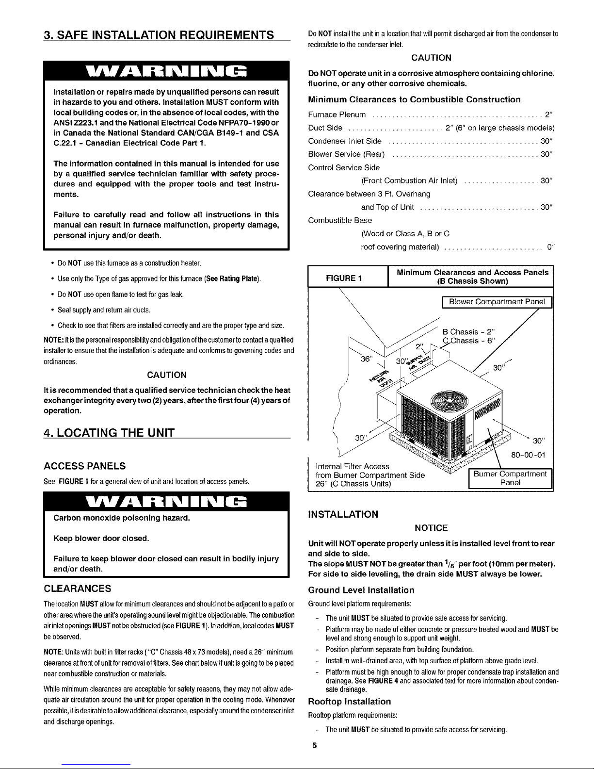
Minimum Clearances to Combustible Construction
Furnace Plenum ........................................... 2"
Duct Side ........................ 2" (6" on large chassis models)
Condenser Inlet Side ...................................... 30"
Blower Service (Rear) ..................................... 30"
Control Service Side
(Front Combustion Air Inlet) ................... 30"
Clearance between 3 Ft. Overhang
and Top of Unit .............................. 30"
Combustible Base
(Wood or Class A, B or C
roof covering material) ......................... 0"
FIGURE 1
\
I Minimum Clearances and Access Panels
(B Chassis Shown)
Blower Compartment Panel
I nternal Filter Access
from Burner Compartment Side
26" (C Chassis Units)
30"
80-00-01
Burner Compartment
Panel
Keep blower door closed.
Failure to keep blower door closed can result in bodily injury
and/or death.
CLEARANCES
ThelocationMUSTallowfor minimumclearancesandshouldnot beadjacentto apatioor
otherareawheretheunit'soperatingsoundlevelmightbeobjectionable.Thecombustion
airinletopeningsMUSTnotbeobstructed(seeFIGURE1).In addition,localcodesMUST
beobserved.
NOTE:Units withbuiltinfilterracks( "C" Chassis48x 73 models),need a26" minimum
clearanceatfrontofunitforremovaloffilters.Seechartbelowif unitisgoingtobe placed
nearcombustibleconstructionormaterials.
While minimumclearancesare acceptablefor safetyreasons,they may notallowade-
quateair circulationaroundthe unitfor properoperationinthecoolingmode.Whenever
possible,itisdesirabletoallowadditionalclearance,especiallyaroundthecondenserinlet
anddischargeopenings.
INSTALLATION
NOTICE
Unit will NOT operate properly unless it is installed level front to rear
and side to side.
The slope MUST NOT be greater than 1/8" per foot (10mm per meter).
For side to side leveling, the drain side MUST always be lower.
Ground Level Installation
Groundlevel platformrequirements:
- The unitMUSTbe situatedtoprovidesafo accessforservicing.
Platformmay be madeof eitherconcreteor pressuretreatedwoodand MUSTbe
level andstrongenoughto supportunitweight.
Positionplatformseparatefrom buildingfoundation.
Installin well-drainedarea,withtopsurface ofplatformabovegrade level.
Platformmust be highenoughto allowfor propercondensatetrapinstallationand
drainage.SeeFIGURE4 andassociatedtextfor moreinformationaboutconden-
satedrainage.
Rooftop Installation
Rooftopplatformrequirements:
- The unitMUST be situatedto providesafoaccessforservicing.
Page 6
- TheexistingroofstructureMUSTbeadequatetosupporttheweightoftheunitorthe
roofMUSTbereinforced.
Checktheweightoftheunitin relationtothe roofstructureandlocalbuildingcodes
orordinancesand reinforceroofstructureifnecessary.See FIGURE21onthe back
coverofthis manualforunit weights.
- Supportfortheunit MUSTbelevelandstrongenoughtocarryunitweight.Thesup-
portmayconsistof aplatformoracombinationof platformand roofbeamsorcurb.
- See Hoistingsectionbelowfor hoistinginstructions.
HOISTING
NOTE:All accesspanelsMUST besecuredin placebeforehoisting.
Theunitshouldbe hoistedwithtwo liftingslings.Attachtheslingsto riggingshacklesthat
havebeen hookedthroughholesin the baserail.
TwospreaderbarsMUSTbeplacedontop ofthe unitto protecttheunitfromdamagefrom
thepressureexertedbythe slings.Makesurethatallequipmentisadequatetohandlethe
weightofthe unit andthatthe slingswill not allowthe unitto shift.
RefertoFIGURE21on thebackcoverof thismanualforillustratedrigginginstructionsand
weightchart.
DOWNFLOW CONVERSION
These unitsare adaptableto downflowuse. Toconvert to downflowuse,follow these
steps:
1. Removethe blockoffplatesfoundin the returnaircempartmentandthe supplyair
compartment.SeeFIGURE2.
NOTE:Blockoffplateinthesupplyaircempartmentonlycontainsonescrew.Ifreinstalling
plate,backpartofplateMUSTfitintomatingdimplesonflange.Toreinstall,slantplateinto
dimples,thenput plate intopositionand fastenwithscrew.
2. Instanthe removedplateson thehorizontalreturnand supplyair openings.
3. Installroofcurb on the building.Besure to followall directionsincludedwithcurb
andallapplicablebuildingcodesinyourinstallation.(SeePages2 or3forappropri-
atecurbto usewithyour model.)
FIGURE 2 Blockoff Plate (Return Air Compartment)
I
FIGURE 3 l Heating Vent Assembly
Flue Support
(Shipped mounted to unit
Flue Cover
\
CAUTION
DO NOT OPERATE THE UNIT WITHOUT THE VENT ASSEMBLY
INSTALLED
Condensate Drain
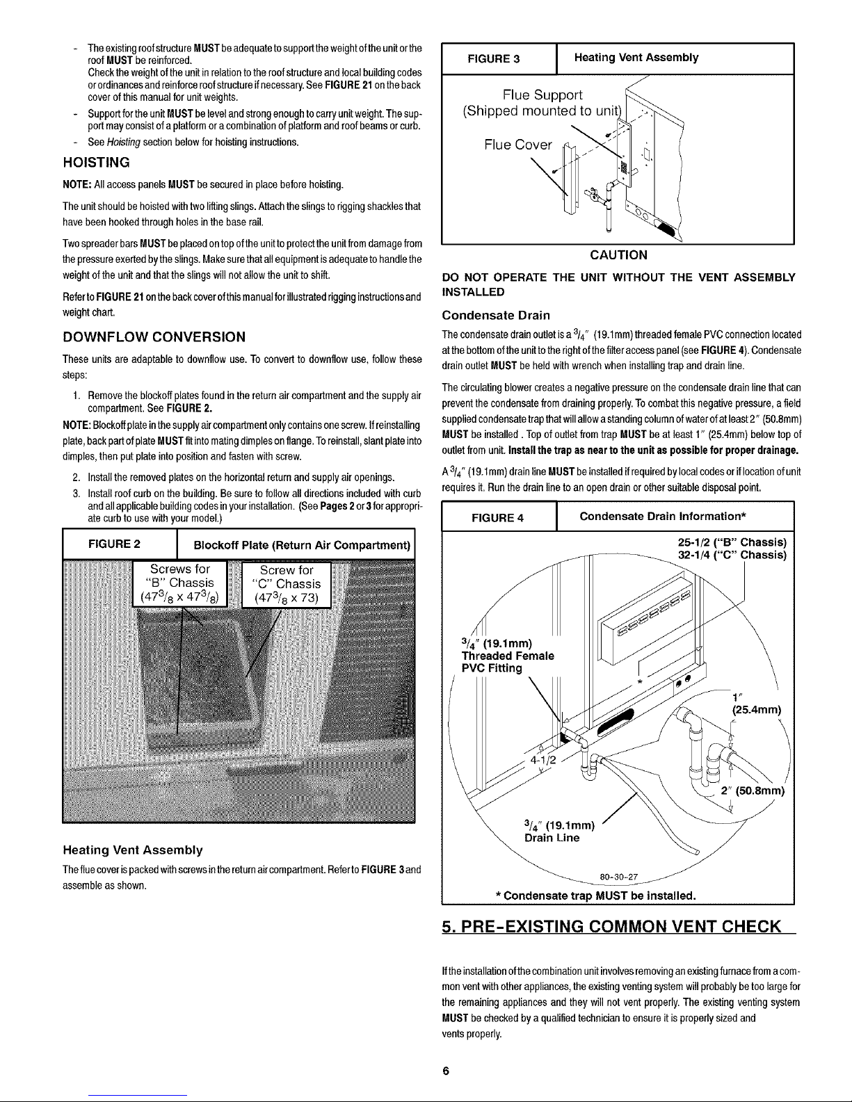
Thecondensatedrainoutletisa 3/4"(19.1mm)threadedfemalePVCconnectionlocated
atthe bottomofthe unittotherightofthe filteraccesspanel(see FIGURE4).Condensate
drainoutletMUSTbe heldwith wrenchwheninstallingtrapand drainline.
Thecirculatingblowercreatesa negativepressureonthe condensatedrainline thatcan
preventthe condensatefromdrainingproperly.Tocombatthis negativepressure,a field
suppliedcondensatetrapthatwillallowastandingcolumnofwaterofat least2" (50.8mm)
MUSTbe installed. Topofoutletfromtrap MUSTbeat least1" (25.4mm)belowtopof
outletfromunit.Install the trapas nearto the unit aspossiblefor properdrainage.
A3/4"(19.1mm)drainlineMUSTbeinstalledif requiredbylocalcodesoriflocationofunit
requiresit.Runthedrainline toan opendrainorothersuitabledisposalpoint.
I Condensate Drain Information*
FIGURE 4
A
25-1/2 ("B" Chassis)
32-1/4 ("C" Chassis)
3/4" (19.1mm)
Threaded Female
PVC Fitting
I r,
(25.4mm)
2" (50.8mm)
Heating Vent Assembly
Thefluecover ispackedwithscrewsinthereturnaircompartment.RefertoFIGURE3and
assembleas shown.
* Condensate trap MUST be installed.
5. PRE-EXISTING COMMON VENT CHECK
Iftheinstallationofthecombinationunitinvolvesremovinganexistingfurnacefromacom-
monventwithother appliances,the existingventingsystemwillprobably betoo largefor
the remainingappliancesand they willnotvent properly.The existingventingsystem
MUSTbe checkedby a qualifiedtechnicianto ensureit isproperlysizedand
ventsproperly.
Page 7

6. GAS SUPPLY AND PIPING
NOTE:Becausethere aremanytypesofliquifiedpetroleum(LP)gases,thetermLPas
usedinthis manualrefersto propanegas. Ifyouintendto useanytypeofLP gas,proper
precautionsMUSTbeusedinthehandling,piping,and useofsuchgas.NOTE:In Cana-
da,installationsMUSTbe performedby licensedLPinstallers.
TheUL/CSARatingPlatelocatedonthesidepanelonthe unitcontainsthemodelnumber,
typeof gasand gas inputrating,and otherimportantinformation.
Fire and/or explosion hazard.
Make certain the unit is equipped to operate on the type of gas
available. Models designated as natural gas are to be used with
natural gas only. Models designated for use with liquefied pe-
troleum (LP) gas are shipped with orifices sized for commer-
cially pure propane gas. They MUST not be used with butane or
a mixture of butane and propane unless properly sized orifices
are installed by a licensed LP installer.
Failure to follow this warning can result in property damage,
personal injury, and/or death.
GAS PIPING
The gassupplyline MUSTbe of adequatesize tohandlethe Btu/hr requirementsand
lengthoftherunforthe unitbeinginstalled.Determinethe minimumpipesizefor natural
gasfromthetable inFIGURE5 orFIGURE6. Basethelengthof therunfrom thegas
meterorsourcetothe unit.
Gas Pipe Size
Btu ratingsofall other gas appliancesMUSTbe consideredfor sizingof maingas line.
Checkgaslineto installationforcompliancewith localcodes or,in the absenceof local
codes,withtheNationalFuelGasCodeANSIZ223.1orin CanadatheNationalStandard
CAN/CGAB149-1 orcurrenteditions.
FIGURE 5
Gas Pipe Size, Length and Btuihr Capacity
for Schedule 40 Iron Pipe (English)
NATURAL GAS
Pipe Length Btu/hr (in thousands)
(includes
Fittings) 3/4" 1" 11/4" 11/2" 2"
20' t90 350 730 1,t00 2,100
40' t 30 245 500 760 1,450
60' t05 195 400 610 1,150
LP GAS
Pipe Length Btu/hr (in thousands)
(Includes
Fittings) 1/2" 3/4" 1" 11/4 " 11/2"
20' t89 393 732 1,496 2,299
40' t29 267 504 1,039 1,559
60' t 03 217 409 834 1,275
Gas Pipe Size, Length and Btu/hr Capacity
FIGURE 6 for Schedule 40 Iron Pipe (English)
Pipe Length
(Includes
Fittings) 3/4" 2"
6.1m 56 615
12.2m 38 425
18.3m 31 337
Pipe Length
(Includes
Fittings) 1/2" 11/2"
6.1 m 55 674
t2.2m 38 457
t8.3m 30 374
NATURAL GAS
kW**
1" 11/4" 11/2"
103 214 322
72 147 223
57 117 179
LP GAS
kW**
3/4" 1" 11/4"
1t5 215 438
78 t 48 305
64 t 20 244
**kW (Kilowatts) is the metric equivalent of Btu/hr.
PIPING AT UNIT
Connections
NOTE: The ruleslistedapplyto naturaland LP gaspipe installations.
1. Ifinstallationisfor LPgas,haveLP gasinstalleruseTW0- STAGEREGULATION
andmakeallconnectionsfromstoragetankto unit.
2. Use blackironor steelpipeandfittingsor otherpipeapprovedbylocal code.
3. Ifceppertubing isused,it MUSTcemplywith limitationsetin Fuel GasCode.
NOTE: Ifa gas connectoris used,it MUSTbe acceptableto local authority.Connector
UUST NOTbeusedinsidethefurnaceorbesecuredorsupportedbythefurnaceorduct-
work.
Fire and/or explosion hazard.
Gas connector M UST be properly installed and can NOT be
used inside the furnace.
Failure to do so can result in property damage, bodily inju-
ry or death,
4. Use pipejointcompoundonexternal(male)threadsONLY.JointcempoundMUST
beresistanttoany chemicalactionofLP gases(NOTAG). DoNOTputpipecom-
poundon last2 threadsof pipe.
5. Usegroundjoint unionsandinstalla drip legno lessthan3 inches(76ram)Iongto
trapdirtandmoisturebeforeit canentergas valve.
CAUTION
Overtightening assembly may cause damage to the gas valve and/or
wiring and may misalign the burners.
6. Use a wrenchongas valvewhenmakingconnectionsto preventgas valvefrom
turning.Do NOTusea pipewrench on the gasvalve body.
7. Providea _t8inch(3ram)NationalPipeThread(NPT)plugfortestgaugecennection
immediatelyupstreamof thegas supplyconnectionto thefurnace ifnoneis sup-
pliedwiththe gasvalveof unit.
8. Installa manualshutoffvalve andtightenanjoints securely.
9. Makesure pilottube and burnerorificesarecheckedfor leakage.
ORIFICES
Orifice Sizes
Orificesizes BUST be matchedto the heatingvalueof the gas (see FIGURE7 and
TABLE1).CheckwithyourgassupplierandtheNationalFuelGas Code ANSIZ223.1.
Page 8

FIGURE8 I Manifold/OrificeMeasurement
NOTE:An LP ConversionKit MUSTbe usedfor conversionto LP gas.
NOTE:For elevationsabove2000 feet (610meters),the Btuinputrating MUSTbe re-
ducodby 4%for each 1000feet (305meters)abovesea level,unlessthegassupplier's
Btuflt3contenthasalreadybeenadjustedfor altitude.Check Table 1.
FIGURE 7 Orifice Sizes
Pilot
Gas Specific Btuift 3 Orifice
Type Gravity (kJ/L) Sizes
Natural 0.6 1000 .018#
2500 .012#
Propane
1.53
#Adjust pilot flame as needed
TABLE 1: Equivalent Orifice Sizes at High Altitudes
(Includes 4% input reduction for each 1,000 ft.
NaturalGasManifoldOrificeSize Requiredby Elevation
BTU 0'- 2000' 4500'
INPUT 2000' 4000' 5000' 6000' 7000' 8000' 9000' 10000'
40.000to 44 45 46 47 47 48 48 49
60,00
90,000to 43 44 45 45 46 47 47 48
150,000
LPGas ManifoldOrifice Size RequiredbyElevation
BTU 0'- 2000' 4500'
INPUT 2000' 4000' 5000' 6000' 7000' 8000' 9000' 10000'
40.000to 55 56 56 56 56 56 56 57
60,000
90,000to 54 55 55 55 55 56 56 56
150,000
* 2-1/2 & 3 Ton with 3 burners.
** 3-1/2 & 4 ton with 4 burners.
Changing Orifices
Electrical shock, fire and/or explosion hazard.
Sh ut off electric power at unit discon nect or service panel and
shut off gas at manual shut off valve before beginning the fol-
lowing procedure.
Changing orifices requires a qualified service technician.
Failure to follow this warning can result in property damage,
personal injury, and/or death.
1. Shut OFFgasat manualshutoffvalve.
2. Shut OFFelectricpoweratunit disconnector servicepanel.Ifunit isstillrunning,
allow2.5 minutesafter gasshut off beforeturningoffpower.
3. Disconnectthewiresfromthe gasvalve.
4. Removethe four screwsholdingthe manifoldtothe manifoldbrackets.
5. Carefullyremovethe manifoldwiththe gas valveattached.
6. Removethe orificesfromthemanifoldwith a 7/16"box end orsocketwrench.
7. Checkto be surethat the sizeof eachorificeis correctforthe Btu inputdesired.
Measure 11/16" (27mm) from
face of orifice to back edge of
_ manifold pipe.
8. Installthecorrectorifices.Gaugethesizeoftheorificeswitha newtwistdrillbit ofthe
correctsize.
Makesurethattheorificesgoinstraightsothat theyforma rightangle (90°) to the
manifoldpipe.
Tightenthe orificessothat thereisa 11/16" (27mm)distancebetweenthefacesof
theorificesto theback ofthe manifoldpipe.
Measurethe distancewitha setof calipers.Ifyoudo nothavea calipers,you can
use an adjustablewrenchand measurebetweentheface ofthejaws.
9. Reassembleinreverseorder.
7. ELECTRICAL WIRING
Electrical shock hazard.
Disconnect power at fuse box or service panel before making
any electrical connections.
Unit MUST be grounded to electrical service panel.
Failure to follow this warning can result in property damage,
personal injury, and/or death.
NOTE:All electricalworkMUSTconformwiththerequirementsof localcodes andordi-
nancesandthe NationalElectrical CodeANSI/NFPA-No.70-1990 or currentedition.
Providelinevoltagepowersupplyfromaseparatefusedcircuitwithadisconnectswitch
locatedwithinsight of theunit.
Foraccess,removetheheateraccesspanelandthecontrolboxcover.See FIGURE1for
accesspanellocation. Wiring MUSTbe protectedfrom possiblemechanicaldamage.
Line Voltage Wiring
Connectionsforlinevoltagearemadeinthe unitcontrolbox.Foraccess,removetheburn-
er accesspanelandthe controlboxcover.
Ground Connections
DoNOTcompletelinevoltageconnectionsuntilunitispermanentlygrounded.Alllinevolt-
ageconnectionsand theground connectionMUSTbe madewith copperwire.
Agroundlugisinstalledinthe controlboxforthegroundconnection.Useacopperconduc-
torof theappropriatesizefromthe unitto agroundedconnectionintheelectricalservice
panelor a properlydrivenand electricallygroundedgroundrod.Seewarning above.
Line Connections
Completethelineserviceconnectionstothe contactor'L'terminalsinsidethecontrolbox.
Refertoapplicablewiringdiagram.Checkallscrewterminalsto ensurethey aretight.
THERMOSTAT/HEAT ANTICIPATOR
Thelocationofthethermostathasanimportanteffectontheoperationoftheunit. FOL-
LOW THE INSTRUCTIONSINCLUDEDWITH THETHERMOSTATFOR CORRECT
MOUNTINGANDWIRING.
Set thethermostatheatanticipatorto.58 in accordancewiththermostatinstructions.
Page 9

FinalElectricalCheck
1. MakeafinaIwiringchecktobe suresystemiscerrectlywired.Inspectfieldinstalled
wiringandtheroutingtoensurethatrubbingorchafingduetovibrationwillnot occur.
NOTE:Wiring MUSTbe installedsoit isprotectedfrompossiblemechanicaldamage.
8. DUCTWORK
Maximum recommendedvelocity in trunk ducts is 1000 feet per minute.Velocity in
branchesshould notexceed 800feetper minute.
FIGURE 9 Capacities Air Delivery
Nominal Tons
Air Conditioning
Up Thru 2
21/2
3
31/2
4
41/2
5
61/3
Nominal Air
Flow Cubic Feet
per Minute
800-900
900-1100
1100-t300
Recommended Filter Sizes
Sq. In. Surface Area/Nominal Size
Disposable Filters Cleanable Filters
400 or 20 x 25 246 or 15 x 20
487 or 20 x 30 301 or 14 x 25
576 or 14 x 25 (2Req.) 356 or 16 x 25
Unit Size
Heating Input
1000 x Btuh
40 and 50
40, 50, 75 and 100
40, 50, 75 and 100
1300-1500 665 or 16 x 25 (2Req.) 411 or 20 x25 (2Req.) 75, 100 and 125
1500-1700 753 or 20 x 25 (2 Req.) 466 or 20 x 25 100 and 125
1700-1900 841 or 20 x 25 (2 Reg.) 521 or 24 x 25 125
1900-2100 960 or 20 x 30 (2 Req.) 575 or 24 x 25 125
2300-2500 1108 or 20 x 30 (2 Req.) 685 or 24 x 30 150
NOTE: Minimum recommended filter areas are based on a velocity of 325 ft./rain, for disposable filters and 525 ft./min, for high velocity filters (washable).
NOTE:Ductworksizingaffectstemperatureriseandcoolingtemperaturedifferential.Be
sureto properlysizeductworkto thecapacityandairflowcharacteristicsofyour unit.Fail-
uretodoso canaffectlimitcontrols,compressors,motors,andothercomponentsandwill
leadto prematurefailure ofcomponents. Thiswillalsoadverselyaffectday to dayunit
performance.Referto rating plateand TemperatureRiseCheck,Page21.
Ductwork Insulation
Ductworkinstalledoutdoorsshould have a minimum of2" fiberglassinsulationand a
weatherproofvapor barrier,tt shouldbe protectedagainst damage.Caulkingand flash-
ings,orother meansadequatetoprovidea permanentweatherseal,should beused.
Ductworkinstalledin atticsor other areas exposedto outsidetemperaturesshould be
installedwithaminimumof2" fiberglassinsulationandhavean indoortypevapor barrier.
Ductwork Connections
Theuseofflexible, non-combustibleconnectorsbetweenmaintrunk ductsand supply
andreturnair plenumsis recommendedto minimizevibrationtransmission.
NOTE: Connectsupplyandreturnairplenumsto unitina mannerthatwillallowthe top of
theunitto beremovedwithoutremovingplenums.PlenumsMUST beindividuallysealed
tounit casingwithductsterminatinginsidestructure.
FILTERS
Allreturnair MUSTpassthroughafilterbeforeenteringtheunit.Anelectronicaircleaner,
optionalfilterracks,or otheraccessiblefilterarrangementMUSTbeinstalledinthe return
airductwork.MinimumrecemmendedfilterareasarelistedinFIGURE9andarebasedon
avelocityof325 _min for disposablefiltersand 525 ft!minfor highvelocityfilters(wash-
able).
CAUTION
9. START-UP PROCEDURES
Fire and/or explosion hazard.
Do NOT attempt to light the pilot or burner with a match or
flame of any kind.
Failure to follow this warning can result in property damage,
personal injury, and/or death.
CHECK BEFORE STARTING
1. Checkthat the blowermotor speed terminal block or thesetting of the variable
speedpulleyisrunningthe correct heatingand coolingspeeds.
2. Checkto seethatclean, properlysizedairfilters areinstalled.
3. Replaceall serviceaccesspanels.
Reverse Rotation (Scroll Compressors Only)
ThreephasescrollcompressorequippedunitsCANrunin reverseif improperlywired.If
thecompressormakesanunusuallyloudnoise,orif highandIowsidepressuresarenear-
lyidentical,thisindicatesreverserotation.Tocorrect,reverseanytwowiresatlinevoltage
connectionsONLY. DoNOT re-wireanycircuitsinsidethe unitto attemptcorrectionof
reverserotation.
Manifold Gas Pressure Adjustment
NOTE:Makeadjustmentto manifoldpressurewithburnersoperating.
DO NOT OPERATE THE UNIT WITHOUT A FILTER.
Page 10

Fireorexplosionhazard.
NOTE: Adjustmentscrew coverMUSTbe placedon gasvalvebefore readingmanifold
pressureand operatingfurnace.
Turn OFF gas at shut off before connecting U-tube ma-
nometer.
Failure to properly seal duct can result in personal injury
and/or death.
I
FIGURE 10
[ Honeywell Gas Valve
Inlet Pressure
Tap (Hidden)
Wiring
Terminals
INLET
Outlet
Pressure
Tap
Pilot Adjustment
25-50-06
GAS PRESSURES
1. Do NOTallowgas supplypressuretofall belowthelistedminimums.Doingso wUl
decreaseinputtofurnace.Referto FIGURE11 for gassupplypressures.
2. GasinputMUSTNOT exceedratedinputshownonratingplate.
3. Do NOTallowpressuresto exceedthemaximumlimitsas listedin FIGURE11.
FIGURE 11 Gas Pressures
Natural Gas LP Gas
Minimum 4.5"W.C. (1120 Pa) 1t" W.C. (2740 Pa)
Inlet
Recommended 7" W.C. (t740 Pa) 1t" W.C. (2740 Pa)
Inlet
Maximum 13" W.C. (3230 Pa) 13" W.C. (3230 Pa)
Inlet
Manifold 3.5" W.C. (870 Pa) 10" W.C. (2490 Pa)
Pressure
Manifold Pressures
Manifoldpressuresare coveredin the startupproceduresection.Refer to Chapter 9
Start-Up Procedureson Page20.
1. Withgas OFF,ConnectU-Tubemanometertotappedopening ongas valve.Use
manometerwitha 0to 12incheswatercolumnrange.
FIGURE 12 Manifold Pressure Settings
Gas Type Manifold Pressure
Natural 3.5 Inches Water Column (870 Pa)
Propane 10 Inches Water Column (2490 Pa)
2. TurngasONand removeadjustmentscrewceverongasvalve.Turnccunterclock-
wisetodecreasepressureand clockwiseto increase.
Fire and/or explosion hazard.
Do NOT adjust manifold pressure more than ± 0.3 inches
water column to obtain rated input.
Failure to properly set input pressure can result in proper-
ty damage, personal injury and/or death.
3. Set pressuretovalueshowninFIGURE12, -+0.07kPa(0.3inches)waterceNmn.
Pressureisalsolistedonfurnaceratingplate.InNOcaseshouldfinalmanifoldpres-
surevarymorethan -+0.07kPa(0.3inches)watercolumn.
CIRCULATING AIR BLOWER
Checktheunit'soperationasoutlinedinthefollowinginstructions.If anyunusualsparking,
odorsorunusualnoisesareencountered,shutoffelectricpowerimmediately.Recheckfor
wiringerrors,or obstructionsinornear blowermotors.
1. SetthermostatHeat-Coolselectorto OFF
2. Set thermostatfan switchto AUTO.
3. TurnelectricpowerON. Nothingshouldstartrunning.
4. Turn manualgasvalve ON.
5. Turngas controlvalve ON.
6. Set thermostatfan switchto ON.
7. Resetthermostatfan switchto AUTO.
HEATING START-UP PROCEDURE
1. Adjustthermostatsetting aboveroomtemperatureandset thermostatselectorto
HEAT.The combustionair blowershouldcome ON.
2. Theignitorshouldbeginto glowand pilotflameshouldlight.Referto Lighting/Oper-
atingInstructionslabel locatedon BurnerAccess Panelof unit.
NOTE:On acall forheat theignitorand pilotvalvewill remainenergizeduntila flameis
detectedby the flamesensor. It maytakeseveralminutesto purgethe air outof thegas
linesat initialstart-up ofthe unit.
3. Once theflame sensordetectsthata flameis present,the hotsurfaceignitorwill
de-energizeand themain burnerswill lightfrom the pilot.
4. 30 secondsafterthe burnerslight,the circulatingblowershouldbeginto run.
Fire and/or explosion hazard.
Do NOT attempt to light the pilot or burner with a match or
flame of any kind.
Failure to follow this warning can result in property damage,
personal injury, and/or death.
Temperature Rise Check
NOTE:Air temperatureriseisthe temperaturedifferencebetweensupplyand returnair.
Witha properlydesigneddistributionsystem,the properamountoftemperaturerisewill
normallybeobtainedwhentheunitis operatingatratedinputwiththe recommendedblow-
er speed.
The temperature rise must be within the specifications marked on the unit
rating plate.
To check the temperature rise through the unit, place thermometers in the
supply and return air ducts as close to the unit as possible,
Open ALL registers and duct dampers, Operate unit AT LEAST 15 minutes
before taking readings.
If the correctamountof temperatureriseis not obtainedwhenoperatingonthe recom-
mendedblowerspeed,itmay be necessarytochangetheblowerspeed.A fasterblower
speedwilldecreasethe temperaturerise.Aslowerblowerspeedwillincreasethetemper-
aturerise.
10
Page 11

NOTE:TheblowerspeedMUSTbesettogivethe correctairtemperaturerisethroughthe
furnaceas markedon theratingplate. SeeFIGURE14 for moreinformation.
3. After 15minutesofoperationcheckthelimitcontrolfunction byblockingthe
returnairgrille(s).
AfterseveralminutesthemainburnersandpilotshouldgoOFEThe circulatingair
blowershould continuetorun.
Removeairrestrictions.Pilotandmainburnersshouldrelightafteracooldownperi-
odof afew minutes.
4. Adjustthethermostatsettingbelow roomtemperature.
Pilotand mainburnersandcombustionair blowershouldgo OFE
Thecirculatingairblowershouldcontinueto runfor 60, 100, t40 or t80 seconds.
Thistime isadjustable. See FIGURE13formore information.
5. Set thermostatHeat-Cool selectortoOFE
FAN CONTROL CHECK
FIGURE 13 / Fan Delay DIP Switch Settings
1
Fan Off Delay (140 sec. is factory setting)
60 sec 100 sec 140 sec 180 sec
Fan On Delay (30 sec. is factory setting)
1 2 3
60 sec
1 2 3
30 sec
The FanControlhasadjustablesettingsforthecirculatingairblowertodelay it "ON" and
"OFF".
1. The"ON" delayisfactorypre-setat 30seconds. Itcanbe adjustedto60seconds.
2. The"OFF" delayisfactorypresetat 140seconds. Itcanbeadjustedto60,100 and
150seconds,respectively.
Referto FIGURE13for properDIP switchsettings.
3. Operatethefurnaceand ensurethatthe blowerturnsON and OFFattheappropri-
atetimeto providethedesiredcomfortlevel.
SPEED TAPS
AfterdeterminingnecessaryCFMandspeed tapdata,followthesteps belowto change
speeds.
1. Referto FIGURE14 andlocatethespeedtap blockonblower motor.
2. TheyeUowleadMUSTalwaysbe connectedtothespeedtap blockatthe common
quickconnectterminal.Theterminalisidentifiedas COM.Also,this isthe onlylead
whichis3116"wide.All otherquickconnectsare 114"wide.
3. Ifit hasbeen determinedthatcoolingandheatingspeedsareneededonthe same
speedtap, removethered heatingleadfromthe speedtap blockandconnectitto
theinsulatedmaleterminalonthe blackcoolinglead.Then placetheinsulatedblack
femalequickconnectto the requiredspeedtap.
CONTINUOUS FAN OPERATION
Anoptionalterminalmaybe providedon theelectronicfan controllocatedinthe electrical
controlbox foroperationofthe continuousfanoption. Thisconnectionisintendedforthe
lowspeedmotortap,andhas a lowercontactrating(8amps)thantheheatandcooltaps.
Whenthelowspeedblowerleadisconnectedto thisterminal,thiswillprovidelowspeed
bloweroperationwheneverthe othertwospeeds (Heator Cool) arenot energized.
Thoroughlycheckthe systemaftermodificationtoensuretheproperoperationofthecircu-
latingair blowerinallmodesof operation.
Separate Speed Selections for Heat, Cool and Continuous
Fan
Connectlowspeedleadfromcirculatingmotortothe"Cent"terminal atthe electronicfan
control. The appropriatemotor leadsshould already be connectedto the "Heat" and
"Cool" terminals.
Note: Seenextsection"Heatingand ContinuousBlowerSpeedthe Same"iflowspeedis
requiredfor heatingto obtaindesiredtemperaturerise.
Heating and Continuous Blower Speed the Same
If is is necessaryto operate theheatingspeedand continuousblowerspeed usingthe
sameblowerspeed, connecta jumperbetweenthe "Heat" and"Cont" terminalsonthe
blower.
Note: Thereshouldbe onlyONEmotor lead goingto the"Heat" and "Cont" terminals.
COOLING
1. Turnelectricpower OFF
2. Set thermostatHeat-Cool selectto COOL
3. Adjustthermostatsettingto belowroomtemperature.
4. TurnpowerON,forapproximatelyone minute,then OFE Duringpowerapplication
checkthefollowing:
a.Contactor- ContactsClosing
b.Compressor- ON
c. Condenserfanmotor - ON
d.CirculatingAir Blower - ON aftera 30seconddelay
5. Turn powerOFF,checkthefollowing:
a. Contactorcontactsopening.
b. Compressor- OFF
c. Condenserfanmotor- OFF
d. Circulatingblower - OFF aftera 30seconddelay.
Page 12

FIGURE 14 I Blower Motor Speed Taps (3-Speed and 4-Speed Motors)
I BE SURE TO CHECK BLOWER MOTOR I
SPEED DATA IN UNITS
TECHNICAL INFORMATION LABEL
ON THE UNIT
10. OPERATION
Electrical shock hazard.
Turn off electric power supply at disconnect switch or service
panel before removing any access or service panel from unit.
Failure to follow this warning can result in property damage,
personal injury, and/or death.
COMBUSTION/INDOOR FAN CONTROL
Allfunctionsofthecembustionandindoorblowerarecontrolledbythefancontrolmodule.
Ona callfor heat:
Thefancontrolenergizesthecembustionblower.Oncethecombustionairprovingswitch
closes,theignitionsequencebegins.Thefan controlwillsensewhenthemainoperatorof
gasvalvehasbeenenergizedtherebyfiringtheburnersandstartingthe "delayon"timing
sequenceof the indoorblower.
NOTE: Ifthecontrolsensesthatone ofthe safety limitshasopened,thecombustionand
indoorfans willoperateuntilthe limitresets.
Ona callfor cooling:
Thefancontroldelaysthestartoftheindoorblowerfor30ceconds.0ncethethermostatis
satisfied,thefan controlwilloperatetheblowerfor30 additionalseconds.
\
-\
\
SCROLL ANTI-CYCLE TIMER
Single phasescrollcompressorequippedunits are equipped withan anti-cycle device
whichdelaysstartofthecompressorinthe eventofa powerinterruption.Thisfeatureisto
allowpressureequalizationthroughoutthe systemandto preventpossiblereverserota-
tion ofthescrollcompressor.Three phaseunitsdo notrequirethis device.
11. MAINTENANCE
MONTHLY MAINTENANCE AND INSPECTION
CHECKS
Air Filters
CAUTION
Do NOT operate without air filters.
Inspectfiltersat leastmonthlyandreplaceorcleanasrequired.Washablefiltersmaybe
cleanedbysoakinginmilddetergentandrinsingwithcoldwater.Replacefilterswiththe
arrowsonthesidepointinginthedirectionofairflow.Dirtyfiltersarethemostcommon
causeofinadequateheatingorcoolingperformance,andofcompressorfailures.
HEATING SEASON CHECKS (MONTHLY)
Pilot Flame
Whilethemainburnerison,theflameshouldenveloptheupperpartoftheflamesensor.
Main Burner Flame
Flamesshouldbestableandsolidblue,(dustmaycauseorangetipsortheymayhave
wispsofyellow,buttheyMUSTnothavesolidyellowtips).Theyshouldextenddirectlyinto
12
Page 13

theheatexchangertubesandtheturbulatorsshouldgloworange(afteraboutfiveminutes
ofoperation).Mainburnerflameshouldbeinspectedmonthly.
FIGURE 15 I Normal Flame
i
Turbulator will glow
orange when hot.
Flame should be
stable and solid
blue.
Usingalightand mirror (asrequired)inspecttheinsideofthe venthood and theinlet air
openinginthe burnercompartment. Lookfor sootand severerustorcorrosionandany
obstructionsdueto leaves,spiderwebs,etc. Cleanas required.
COOLING SEASON CHECKS (MONTHLY)
Condenser Coil
Keepthe condenserinletandoutletareacleanandfreeofleaves,grassclippingsorother
debris. Grassshouldbe kept shortin frontof the condenserinlet. Shrubbery MUSTbe
trimmedbackso it is nocloserthan 30 inchesto unit.
Condensate Drain
Checkfor condensatedrainage. Cleanas required.
NOTE: Whenunit isoperatingincooling modeunderhighhumidityambientconditions,
condensatecan form in the burner compartmentand may drip from the front of the
compartment.Thisconditionis NOTharmfulto the unit.
ANNUAL MAINTENANCEANDINSPECTION
Electrical shock hazard.
Turn off electric power supply at disconnect switch or service
panel before removing any access or service panel from unit.
Failure to follow this warning can result in property damage,
personal injury, and/or death.
Theannualinspectionshouldincludelubricationandcleaningas requiredtoensureeffi-
cientoperationoftheunit.Tosimplifyaccess,removeallaccesspanelsandthe top from
theunit ifpossible.
Condenser Fan Motor
Oilthecondenserfanmotor afterfiveyears of operationandeveryfive yearsthereafter.
VENT ASSEMBLY
Burn hazard.
Flue cover may be hot! Allow adequate time for flue cover to
cool.
Failure to follow this warning can result in property damage
or personal injury.
UseSAE 10W30motoroil.Tooil,removetheholeplugsfromthemotorendbellsand add
severaldrops(approximately1/2teaspoonful)ofoilwithasqueezetype,flexibletubeoiler.
Replacehole plugsafteroiling. Donot overoil.
Cleanthesurroundingareaandthecondenserandevaporatorcoils.Usecautiontoavoid
damagetocoil fins.
BLOWER MOTOR ACCESS
RefertoFIGURE16foraviewofblowermotorandcompartment.
FIGURE 16 Blower Motor and Housing
Method 1
Thismethodallowsyoutoworkonthemotorandhousingwhilestillintheunit.The blower
motorcanbe replacedwiththismethod,butsomemaypreferto work onthe housingas-
semblyseparately.Ifthis is your preference,usemethod2.
1. Removethe bloweraccesspanel
2. Removethe fourscrewssecuringtheblower motorhousing.Ifunit hasa support
bracket,removethetwo screwssecuringthebracket.
3. Removethe two redwiresattachedto the limitswitch.
4. Slideentirehousingtowardyou.Thiswillalloweasieraccesstothespeedtapblock,
motor,and wires.
5. After access,replaceall wires,screws,andconnections.
Motor removal and replacement
Theblower motormaybereplacedwhile accessingit usingmethod1. Toreplacemotor,
reach behindblowerhousingand locate blowerwheelsetnut. Loosenset nut,allwires
frommotor,andfourpinsonmountingcradle.Pullmotortowardsyou.Toreplacemotor,
reversethisprocedure.
Method 2
Thismethodisrequiredtoreplaceorrepairblowerwheel,blowerhousing,oranyunreach-
able componentsbehindblowerassembly.
1. Repeatsteps 1through 4in method 1.
13
Page 14

2.Removeallscrewsaroundrimofunittop,(exceptscrewswhichareinaccessible
becauseofproximitytostructure).
3.Raiseunittopatcernerofunitctosesttobloweratleast2"andplaceasturdybrace
atleast2"thickbetweentopandunitcorner.SeeFIGURE17.A2X4pieceofwood
isidealforthis.
4.Disconnectallwiresfromhousingandslidehousingoutofunit.Reversethisprom
cesstoreinstall.
FIGURE 17
Circulating Air Blower
Blower Access Showing Lid
Propped with 2X4
Visuallyinspectthe blowerwheelfor accumulationsof dirtorlint. Cleanthecompartment
andthe blower wheel.If accumulationisexcessiveonblower wheel,or does noteasily
remove,itwillbe necessaryto removethe blowerassembly.
Oilblowermotorby adding1I2teaspoonful(lcc) of SAE 10W30to eachmotorbearing.
The blowermotorshouldbe oiledafterfiveyearsof operationandevery fiveyearsafter.
CAUTION
Do not use 3 in I oil, penetrating oil, WD40 or similar oils to oil motor
bearings.
Burners / Heat Exchangers / Flue Gas Passages
Toinspectthe burners,heat exchangerand interiorflue gas passages,usea light and
smallmirroron an extensionhandle.
Checktheexteriorofthe heatexchangerandthe interiorflue gaspassagesforany evi-
denceof deteriorationdueto corrosion,crackingor other causes.Ifsigns ofscalingor
sootingexist,removethe burnersand clean theheat exchanger,asrequired.
INSPECTION AND CLEANING OF BURNER
ASSEMBLY/HEAT EXCHANGERS/FLUE GAS
PASSAGES
For Qualified Service Technician Only
See FIGURE18, FIGURE19 and FIGURE20foridentificationofparts.
1. Disconnectelectricalpowertounit.
2. TurnOFFgasatmanualshutoftvalve.
3. Removeburneraccesspanel.
4. Removetheventassemblyfluecover.
5. Disconnectgas pipeatunion.
6. Disconnectwiresfrom gasvalve,noteconnections.
7. Removescrewsthatsecuretheflameshieldand removegascontrolvalve,man-
ifoldand burnersas anassembly.
8. Removecollectorbox,injectorplate,and restrictorplate, includinggaskets.See
FIGURE19.
9. Holdthe burnerassemblyverticallyandlightly tapit againsta woodblock. Clean
alsowithastiffbrush.Severecasesoflintcloggingmayrequirewashingtheburners
in hotwater.
10.Removeturbulatorsand clean with small brush.Reinspectaftercleaningand re_
placeturbulatorsif defective.
11.Cleanfluegas passagesbyusingsmall brushesanda vacuumcleaner.It maybe
necessarytofabricatehandleextensionsforthebrushestoreachtheareasthat re-
quire cleaning. Reinspect after cleaning and replace the heat exchanger if
defective.
12.Reinstallpartsand gasketsin reverseorder.Onsparktopilotmodelscheck
thesparkgap. 1t8inchis requiredbetweenthe igniterand pilot hood.
13.Turn gason and checkfor leaks.
14.Installall accesspanels,turnpoweronand checkfor normaloperation.
FIGURE 18 Access to Burners
FIGURE 19
Burners, Valve, and Burner Box
Removed
FIGURE 20 Burner Assembly Removed
Gas Valve
14
Page 15

RIGGINGINSTRUCTIONS
A WARNING
FAILURE TO FOLLOW THESE INSTRUCTIONS
CAN RESULT IN PROPERTY DAMAGE,
BODILY INJURY OR DEATH.
ALL PANELS MUS] BE IN PLACE WHEN RGGING AND I FliNG.
HOOK RIGGNG SHACKLES _HROUGH HOLES IN BASE RAL, AS SHOWN IN DEw,AlL A
USE SPREADER BARS, WHLN RGGNG, TO PREVLNT UNIT DAMAGE.
BE SURE RIGGNG AND SHACK ES ARE SUFFCIENT TO HAND E WEGHT ISTED BE OW.
SPREADER BARS
DETAIL A
HEIGHT
CAB NET
B
C
LENGTH /
WIDTH
COOING
CAPAC TY
RANGE
.53.5 TONS
.}6.3 TONS
LENGIH
N MM
48,00 1219
73.00 185
WIDTH
IN MM
48.00 1219
48,00 1219
HEIGHT
iN MM
35_00 838
36.50 927
MAX_ WEGql
LB KG
450 204
700 318
"11
0
C
m
c
o
m_
o
Page 16

14. Notes
16
Page 17

INTERNATIONAL COMFORT PRODUCTS
LIMITED WARRANTY CERTIFICATE
For Cooling & Heating Products
SAVE THIS CERTIFICATE. It gives you specific legal rights, and you may also have other rights which may vary from state to state and
province to province.
If your unit needs servicing, contact a qualified dealer or qualified service technician of your choice. When requesting service, please have the model
and serial number from each unit in your heating and/or cooling system readily available. Ifyour dealer needs assistance, the distributor is available to
provide support and we, in turn, support its efforts.
Fill in the installation date and model and serial numbers of the unit in the space provided below and retain this Limited Warranty for your files.
GENERAL TERMS
Subject to the conditions and limitations stated herein, during the term of this Limited Warranty, we will provide a replacement for any functional
component part (as defined below) of your unit found to be defective in materials or workmanship. The term of this Limited Warranty is five years from
installation on Residential Products and one year from installation on Commercial Products. Except as otherwise stated in the "Additional Terms"
section, this Limited Warranty covers only the original purchaser and subsequent transferees, and only while the unit remains at the site of the original
installation (except for mobile home installations), and onty if the unit is installed inside the continental United States, Puerto Rico, Alaska, Hawaii or
Canada. In addition, the Limited Warranty applies only if the unit is installed and operated in accordance with the printed instructions accompanying the
unit, and in compliance with alt applicable installation and building codes and good trade practices. As used in this Limited Warranty, "installation"
means the original installation of the unit.
TH ERE ARE EXCEPTIONS to this Limited Warranty as described on the reverse side of this page. All replacement parts will be warranted for the
unused portion of the warranty coverage period on the unit. The part to be replaced must be returned by the dealer to a distributor that sells products for
International Comfort Products, in exchange for the replacement part. In lieu of providing areplacement part, we may, at our sole option, refund to you
an amount equal tothe distributor's component purchase price from us, orprovide to you acredit equal to that amount to be applied toward the purchase
of any new unit that we distribute. Ifa credit for a new unit is given in tieu of a replacement part, the rating plate from the unit being replaced must be
submitted on a warranty claim, and you rdealer must make the unit being replaced available to our distributor for disposition. As acondition towarranty
coverage, the unit must receive yearly maintenance, as described in the owner's manual, by a dealer. Satisfactory proof of yearly service by adealer
may be required.
"Functional component parts" include only the following: blower motor, unit-mounted sensors & timers, condenser motor, evaporator coil, condenser
coil, condenser fan, capacitor, transformer, single-phase strip heat elements, expansion device, reversing valve, solenoid valve, service valve,
electronic and electro-mechanical control board, ignitor, ignition module, draft inducer assembly, burner pilot, gas valve, limit control, pressure switch,
relays and contactors, blower wheel, interlock switch, crosslighter, pilot shield, gas & oil burners, oil pump assembly, accumulators and factory installed
driers and strainers.
This Limited Warranty DOES NOT COVER any labor, material, refractory chambers, oii nozzles, refrigerant, refrigerant inspection and refrigerant
reclaiming, freight and/or handling charges associated with any repair or replacement and such charges will be your responsibility.
Toestablish the installation date for any purpose under this Limited Warranty, you must retain the original records that can establish the installation date
ofyour unit. Ifyou donot providesuchdocumentsthe start dateoftheterm ofthis LimitedWarrantywillbe based uponthedate ofunit manufacture, ptus
thirty (30) days. In establishing that the required yearly service has occurred, you must furnish proof of yearly service by a qualified service technician.
This Limited Warranty does not cover: (a) failure or damages caused by accident, abuse, negligence, misuse, riot, fire, flood, or Acts of God (b)
damages caused by operating the unit where there is a corrosive atmosphere containing chlorine, fluorine, or any other damaging chemicals (other
than those found in a normal residential environment) (c) damages caused by an unauthorized alteration or repair of the unit affecting its stability or
performance (d) damages caused by improper matching or application of the unit or the unit's components (e) damages caused by failing to provide
proper maintenance and service to the unit in accordance with this Limited Warranty Certificate and the printed instructions originally provided with the
unit (f) any expenses incurred for erecting, disconnecting, or dismantling the unit (g) parts or supplies used in connection with service or maintenance,
such as refrigerant, refractory chambers, oil nozzles, filters, or belts (h) damage, repairs, inoperation or inefficiency resulting from faulty installation or
application (i) electricity or fuel costs or any increase in electricity or fuel cost whatsoever including additional or unusual use of supplemental electric
heat (j) units which have not had the required yearly maintenance described elsewhere in this limited warranty.
In no event shall we be liable for any incidental, consequential, or special damages or expenses in connection with any use or failure of this unit.
We have not made. do not make. and hereby disclaim any implied condition or implied warranty of fitness for a particular use or purpose, and
anv implied condition or implied warrantv of merchantabilitv, to the fu Ilest extent allowed bv law. We make no express or implied warranties
except as stated in this Limited Warrantv certificate.
No one is authorized to change this Limited Warranty or to create for us any other obligation or liability in connection with this unit. Any implied
warranties shall last for the term of the expressed warranty contained herein. Some states and provinces do not allow the exclusion or limitation of
incidental or consequential damages or do not allow limitations on how long an implied warranty or condition lasts, so the above limitations or exclusions
may not apply to you. The provisions of this Limited Warranty are in addition to and not amodification of orsubtraction from any statutory warranties and
other rights and remedies provided by law.
Please refer to reverse side of this page for additional terms.
Model No.
Serial No. Date Installed
Effective on units installed After July 1, 2002,
USA: International Comfort Products Corporation (USA) • 650 Hell-Quaker Avenue * P.O. Box 128 • Lewisburg, Tennessee 37091 • (931-270-4100)
CANADA: International Comfort Products division of UTC Canada Corporation • 6060 Burnside Court, Unit 1, Mississauga, Ontario L5T 2T5
(905-795-8113).
Manufacturers of Airquest, Arcoaire, Clare, Comfortmaker, Dettson, Hell, Keeprite, Lincoln, Tempstar and other quality brand name private label
products.
Part No. 401 06 1010 18 (Orig. 8/9/2002)
Page 18

ADDITIONAL TERMS FOR RESIDENTIAL APPLICATIONS ONLY
The Additional Terms for the components listed below are in addition to, and subject to, the General Terms on the reverse side of this page.
Warranty coverage is limited to parts that fail due to defect in materials or workmanship during the specified term.
CENTRAL GAS & OIL FURNACE HEAT EXCHANGERS*
Gas Model Series: C9MPV. HgMPV. TgMPV. CgMPT. H9MPT. T9MPT. C9MPD. HgMPD. TgMPD: Limited Lifetime Warranty on heat exchangers. If
a heat exchanger on one of these furnaces fails due to defect in the part, we will provide a replacement part or, at our option, credit toward the purchase
of a new furnace manufactured by us. This additional Limited Warranty runs only to the original purchaser, and tasts only for as tong as the originat
purchaser tives in the home where the furnace is initially installed.** Itis not transferable to any subsequent owner. Ifthe furnace was not installed in the
home owned by the original purchaser, if the original purchaser setls the home to a subsequent owner, or if proof of originat purchase cannot be
provided, then the limited warranty is only for 20 years from the date of original installation.
Gas Model Series: GDL. GNL. TNE. TDE. NTC7. NDC7. NTP6. NDP6. TDE. NTV6. VNE: A replacement heat exchanger will be provided for any
heat exchanger that fails in one of these furnaces due to defect for 25 years from the originat date of installation.
Gas Model Series: NTC6. GNE. GDE. NDN6. NTG3. NDN3. FBF. NBF. NDF. NTN3. NTN6. NNE. N9MPI. N9MP2. FUH: A replacement heat
exchanger witt be provided for any heat exchanger that faits in one of these furnaces due to defect for 20 years from original date of installation.
Oil Model Series: OLR(105, 160, 182), OCF, OLE OUF, NOLE NOUF, OLB, OHB, ODH, FLO, MBO, LBO, NOMF: Limited Lifetime Warranty on
heat exchangers. Ifa heatexchangerononeofthesefurnacesfailsduetodefectinthepart, wewitl provide a replacement part or, at our option, credit
toward the purchase of a new furnace manufactured by us. This additional Limited Warranty runs only to the original purchaser, and tasts only for as
long as the original purchaser lives in the home where the furnace is initially installed.** It is not transferable to any subsequent owner. If the furnace
was not installed in the home of the original purchaser, ifthe original purchaser sells the home to a subsequent owner, or if proof of original purchase
cannot be provided, then the limited warranty is only for 20 years from the date of original installation.
Oil Fired Floor Furnace: NFO: A replacement heat exchanger witl be provided for any heat exchanger that faits due to defect for 10 years from
installation with the following limitation: during the sixth through tenth year, any credit toward your purchase of a component or toward the purchase of
any new unit wilI be in an amount equal to the distributor's purchase price reduced by 20 percent for each year after the fifth year.
ADDITIONAL TERMS FOR OIL FURNACE APPLICATIONS ONLY
1) OIL BURNERS - A replacement for 5 years from date of original installation for Oil Burner Parts.
2) OPTIONAL ACCESSORIES AND FUNCTIONAL PARTS: A replacement for 5 years from date of original installation. (Refractory and
oil nozzles not included)
GAS/ELECTRIC PACKAGED UNITS HEAT EXCHANGERS
Model series: PGAD. PGAA. PGMD. PGME. PGF. GPFM. PGC. GPCM: A replacement for 10 years from original date of installation.
COMPRESSORS:*
1) Premium Model Units: HAC0. HAC2. HAC4. CAC0. CAC2. CAC4. KAC0. TCA0. TCA2. TCA4. HHP0. HHP2. HHP4. CliP0. CliP2. CliP4.
TCH0. TCH2. TCH4. PGME. PYMC. PHAD. PGAD. PA95. PAPC. PAK. APK: Tothe original purchaser a replacement for 10 years from original date
of installation, only if the unit is installed with factory matched coils, except air conditioner condensing units with a nominal SEER of 10 may be matched
with evaporator coils of the same nominal tonnage regardless of manufacturer and in accordance to factory recommendations. This limited 10-year
warranty is not transferable to any subsequent owner. HOWEVER, ifthe unit was not installed in the home owned by the original purchaser, if the
purchaser sells the home to a subsequent owner, or if proof of original purchase cannot be provided, then the limited warranty is only for 5years from the
original date of installation.**
2) All Other Models: Air Conditioners. Heat PumPs. & Combination Gas/Electric Units: NAC0. NAC2. NHP0. NHP2. AO. A2. HO. H2. PGF.
PGC, GPFM, GPCM, PAE APFM, PHE HPFM, PGAA, PGMD, PA55, PH55, PAPA, PYPA: A replacement for 5 years from date of original
installation, onty if: (a) air conditioner condensing units with SEER rating in the range of 10 to 11 SEER are matched with evaporator coils of the same
nominal tonnage regardless of manufacturer and in accordance to factory recommendations, or (b) heat pump condensing units are used with factory
matched coils, unless written approval to do otherwise is obtained from manufacturer.
ADDITIONAL TERMS FOR COMMERCIAL APPLICATIONS ONLY
For purposes of this warranty a commercial application isone in which: the product has over 5 tons nominal cooling capacity, or is designed
for operation with 3 phase electrical power, or is installed in a commercial establishment such as a beauty or hair salon, hospital, school,
restaurant, church, hotel etc..
3-Phase Models: PGF, GPFM, GPF, PGAD, PGME, PGB, PGMG, PGMF, PGS, PGE, APE, PAE, PAB, PAMD, PAS, PAl=,APFM, APF, PHB, PHE,
PYMD, HPB, PHS, CAC, ACC, CAE, ACE, CHC, HCC, CHE, HCE:
The additional Terms of the components listed below are in addition to and subject to the General Terms on the reverse side of this page.
1) GAS FIRED HEAT EXCHANGERS (ALL MODELS):* A replacement for 10 years from date of originat installation.
2) COMPRESSORS (ALL MODELS):* A replacement for 5 years from date of original installation.
3) OPTIONAL ACCESSORIES AND FUNCTIONAL COMPONENT PARTS (ALL MODELS):*
A replacement for 1 year from date of original installation.
4) COMMERCIAL OIL MODELS: OLR210, OLR350, OTF210, AMT3, AMT4, AMP3: Ten(10) Year Limited Warranty on heat exchangers.
*To receive advantage of your limited warranty, you must provide proof of yearly service by a qualified service technician.
**To receive advantage of your warranty, you must retain the original records that can establish the installation date and proof of purchase of the unit.
MINI SPLITS:
Summary - Mini Splits Warranted for one (1) year on all replacement parts.
Additional terms for Mini Splits:
The additional Terms of the components listed below are in addition to, and subject to, the General Terms on the reverse side of this page.
1) Compressors (All Models): A replacement compressor wili be provided for atIcompressors that faii due to defect for 5 years from date of original
installation.
2) Optional Accessories and Functional Components Parts (All Models):
A replacement part will be provided for alt parts that fail due to defect for one (1) year from date of original installation.
Failu re to maintain the equipment through annual maintenance by a qualified service technician shall void the warranty. Proof of service wili berequired
with ati warranty claims. Proof of purchase and installation date must be submitted with ali claims.
 Loading...