

Page 1
Installation Instructions
!
PGF, PGC, PGS, GPFM, GPCM, GPSM
11/2to 5 TON
COMBINATION UNITS
GAS HEAT / ELECTRIC COOL
Models
PGF018K040F
PGF024K040F
PGF024K060F
PGF030K060F
PGF030K080F
PGF036K060F
PGF036K080F
PGF036K100F
PGF042K080F
PGF042K100F
PGF048K080F
PGF048K120F
PGF060K100F
PGF060K140E
PGC018K040F
PGC024K040F
PGC024K060F
PGC030K060F
PGC030K080F
PGC036K060F
PGC036K080F
PGC036K100F
PGC042K080F
PGC042K100F
PGC048K080F
PGC048K120F
PGC060K100F
PGC060K140F
PGS024K060F
PGS030K080F
PGS036K080F
PGS036K100F
PGS042K080F
PGS042K100F
PGS048K120F
PGS060K140E
GPFM18K040F
GPFM24K040F
GPFM24K060F
GPFM30K060F
GPFM30K080F
GPFM36K060F
GPFM36K080F
GPFM36K100F
GPFM42K080F
GPFM42K100F
GPFM48K080F
GPFM48K120F
GPFM60K100F
GPFM60K140E
GPCM18K040F
GPCM24K040F
GPCM24K060F
GPCM30K060F
GPCM30K080F
GPCM36K060F
GPCM36K080F
GPCM36K100F
GPCM42K080F
GPCM42K100F
GPCM48K080F
GPCM48K120F
GPCM60K100F
GPCM60K140F
GPSM24K060F
GPSM30K080F
GPSM36K080F
GPSM36K100F
GPSM42K080F
GPSM42K100F
GPSM48K120F
GPSM60K140E
462 01 1006 00 4-18-05
Printed in U.S.A.
Page 2
[IJ_lliI]I LV4:1l [.,-'][I]l [.,-_
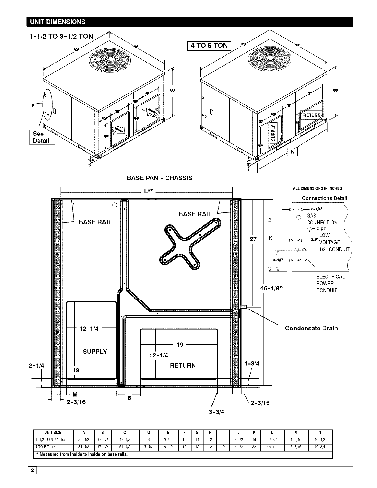
1-1/2 TO 3-1/2 TON
[ 4 TO 5 TON
I/lliI "A"
BASE PAN - CHASSIS
©
BASE RAIL
L_-k
BASE RAIL
12-1/4 --
191 SUPPLY _
I
M
2-3/16
19
12-1/4
RETURN
3-3/4
46 - 1/8"*
2-3/16
ALL DIMENSIONS IN INCHES
Connections Detail
AS /
ONNECTtON (
1/2 \
<F-1-3/4" VOLTAGE _
ELECTRICAL
POWER
CONDUIT
Condensate Drain
UNITSIZE A B C
1-112TO3-1/2 Ton 29-1/2 47-1/2 47-1/2
4 TO5 Ton* 37-1/2 47-1/2 51-1/2
** Measured from inside to inside on base rails.
D E F G H I J K L M
3 9-1/2 12 14 12 14 4-1/2 16 42-3/4 1-9/16
7-1/2 5-1/2 19 12 12 19 4-1/2 22 46-1/4 5-3/16
N
46-1/2
49-3/4
Page 3
3. SAFE INSTALLATION REQUIREMENTS
FIRE, EXPLOSION, ELECTRICAL SHOCK, AND
CARBON MONOXIDE POISON HAZARD
Failure to carefully read and follow all instructions in
this manual could result in furnace malfunction,
property damage, personal injury and/or death.
Installation or repairs made by unqualified persons can
result in hazards to you and others. Installation MUST
conform with local building codes or, in the absence of
local codes, with the ANSI Z223.1 and the National
Electrical Code NFPA70-1990 or in Canada the
National Standard CANiCGA B149-1 and CSA C.22.1 -
Canadian Electrical Code Part 1.
The information contained in this manual is intended
for use by a qualified service technician familiar with
safety procedures and equipped with the proper tools
and test instruments.
• Do NOT use this furnace as a construction heater.
• Use only the Type of gas approved for this furnace (See
Rating Plate).
• Do NOT use open flame to test for gas leak.
• Seal supply and return air ducts.
• Check to see that filters are installed correctly and are
the proper type an size.
NOTE: It is the personal responsibility and obligation of the
customer to contact a qualified installer to ensure that the
installation is adequate and conforms to governing codes
and ordinances.
NOTE: Units with available filter racks ( 3-1/2 to 5 ton), need
a 26" minimum clearance at side of unit for removal of
filters. See chart below if unit is going to be placed near
combustible construction or materials.
While minimum clearances are acceptable for safety
reasons, they may not allow adequate air circulation around
the unit for proper operation in the cooling mode. Whenever
possible, it is desirable to allow additional clearance,
especially around the condenser inlet and discharge
openings.
Do NOT install the unit in a location that will permit
discharged air from the condenser to recirculate to the
condenser inlet.
Do NOT operate unit in a corrosive atmosphere
containing chlorine, fluorine, or any other corrosive
chemicals.
Minimum Clearances to Combustible Construction
Furnace Plenum .................................... 2"
Duct Side ................. 2" (6" on large chassis models)
Condenser Inlet ................................... 30"
Blower Service (Side) .............................. 30"
Contro! Service Side
(Front Combustion Air inlet) ............. 30"
Clearance between 3 Ft. Overhang
and Top of Unit ........................ 30"
Combustible Base
(Wood or Class A, B or C
roof covering material) .................... 0"
I
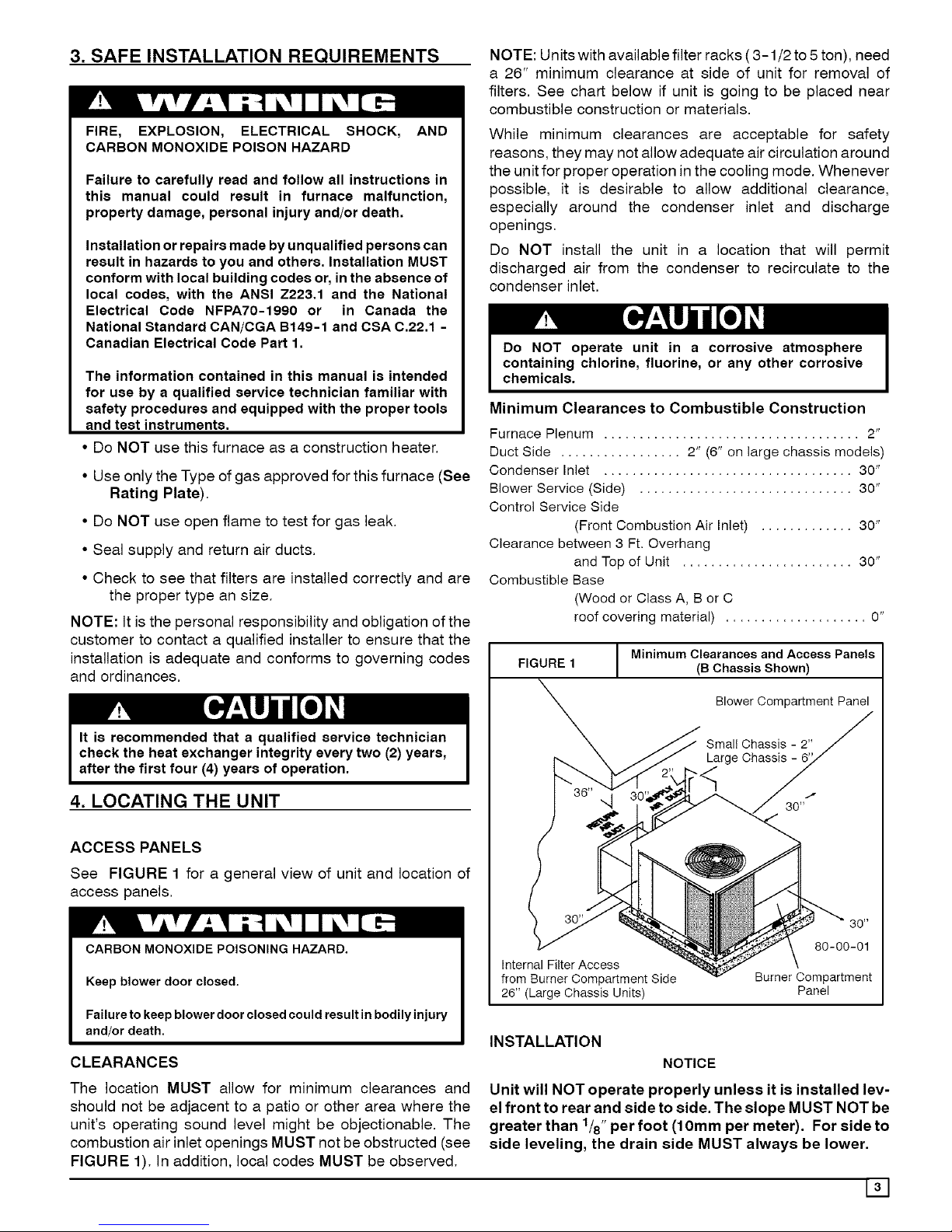
FIGURE 1
Minimum Clearances and Access Panels
(B Chassis Shown)
Blower Compartment Panel
Small Chassis - 2"
Large Chassis
4. LOCATING THE UNIT
ACCESS PANELS
See FIGURE 1 for a general view of unit and location of
access panels.
CARBON MONOXIDE POISONING HAZARD.
Keep blower door closed.
Failure to keep blower door closed could result in bodily injury
and/or death.
CLEARANCES
Internal Filter Access
from Burner Compartment Side
26" (Large Chassis Units)
INSTALLATION
NOTICE
80-00-01
Burner Compartment
Panel
The location MUST allow for minimum clearances and
should not be adjacent to a patio or other area where the
unit's operating sound level might be objectionable. The
combustion air inlet openings MUST not be obstructed (see
FIGURE 1). In addition, local codes MUST be observed.
Unit will NOT operate properly unless it is installed lev-
el front to rear and side to side. The slope MUST NOT be
greater than 1/8"per foot (10mm per meter). For side to
side leveling, the drain side MUST always be lower.
131
Page 4
Ground Level Installation
Ground level platform requirements:
- The unit MUST be situated to provide safe access for
servicing.
Platform may be made of either concrete or pressure
treated wood and MUST be level and strong enough to
support unit weight.
Position platform separate from building foundation.
Install in well-drained area, with top surface of platform
above grade level.
Platform must be high enough to allow for proper con-
densate trap installation and drainage. See FIGURE 3
and associated text for more information about conden-
sate drainage.
Rooftop Installation
Rooftop platform requirements:
- The unit MUST be situated to provide safe access for
servicing.
- The existing roof structure MUST be adequate to sup-
port the weight of the unit or the roof MUST be
reinforced.
Check the weight of the unit in relation to the roof struc-
ture and local building codes or ordinances and
reinforce roof structure if necessary. See the last page
of this manual for unit weights.
- Support for the unit MUST be level and strong enough
to carry unit weight. The support may consist of a plat-
form or a combination of platform and roof beams or
curb,
- See Hoisting section for hoisting instructions,
HOISTING
NOTE: All access panels MUST be secured in place before
hoisting.
The unit should be hoisted with two lifting slings. Attach the
slings to rigging shackles that have been hooked through
holes in the base rail.
Two spreader bars MUST be placed on top of the unit to
protect the unit from damage from the pressure exerted by
the slings. Make sure that all equipment is adequate to
handle the weight of the unit and that the slings will not allow
the unit to shift.
Refer to FIGURE 17 on the back cover of this manual for
illustrated rigging instructions and weight chart.
DOWNFLOW CONVERSION
NOTE: In downflow applications with roof curbs or jack
stands, the center rail under the unit must be removed. The
center rail is attached to the base rail with screws.
These units are adaptable to downflow use. To convert to
downflow use, follow these steps:
1. Remove the blockoff plates found in the return air
compartment and the supply air compartment.
NOTE: Blockoff plate in the supply air compartment only
contains one screw. If reinstalling plate, back part of plate
MUST fit into mating dimples on flange. To reinstall, slant
plate into dimples, then put plate into position and fasten
with screw.
2. Install the removed plates on the horizontal return and
supply air openings.
3, Install roof curb on the building. Be sure to follow all di-
rections included with curb and all applicable building
codes in your installation.
Heating Vent Assembly
Refer to FIGURE 2 and assemble as shown.
FIGURE 2
Heating Vent Assembly
Atta£t?with 2 screws
Heen_ingi__ _
Flue Pipe
DO NOT OPERATE THE UNIT WITHOUT THE VENT
ASSEMBLY INSTALLED
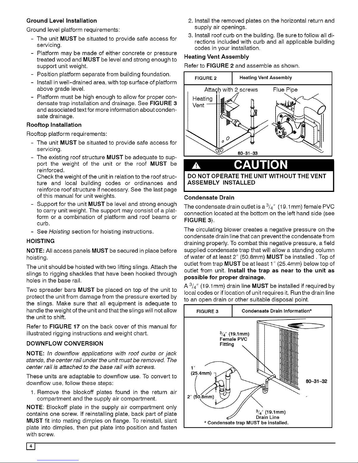
Condensate Drain
The condensate drain outlet is a 3/4" (19.1 mm) female PVC
connection located at the bottom on the left hand side (see
FIGURE 3).
The circulating blower creates a negative pressure on the
condensate drain line that can prevent the condensate from
draining properly. To combat this negative pressure, a field
supplied condensate trap that will allow a standing column
of water of at least 2" (50.8mm) MUST be installed. Top of
outlet from trap MUST be at least 1" (25.4mm) below top of
outlet from unit. Install the trap as near to the unit as
possible for proper drainage,
A3/4" (19.1mm) drain line MUST be installed if required by
local codes or if location of unit requires it. Run the drain line
to an open drain or other suitable disposal point.
FIGURE 3 / Condensate Drain Information*
1
3/4" (19,1mm)
Female PVC
Fitting X
3/4" (19.1mm)
Drain Line
* Condensate trap MUST be installed.
80-31-32
141
Page 5
5. PRE-EXISTING COMMON VENT CHECK
If the installation of the combination unit involves removing
an existing furnace from a common vent with other
appliances, the existing venting system will probably be too
large for the remaining appliances and they will not vent
properly. The existing venting system MUST be checked by
a qualified technician to ensure it is properly sized and
vents properly.
6. GAS SUPPLY AND PIPING
NOTE: Because there are many types of liquified petroleum
(LP) gases, the term LP as used in this manual refers to
propane gas. Ifyou intend to use any type of LP gas, proper
precautions MUST be used inthe handling, piping, and use
of such gas. NOTE: In Canada, installations MUST be
performed by licensed LP installers.
The UL/CSA Rating Plate located on the side panel on the
unit contains the model number, type of gas and gas input
rating, and other important information.
FIRE AND/OR EXPLOSION HAZARD
Failure to follow this warning could result in property damage,
_ersonal injury, and/or death.
Make certain the unit is equipped to operate on the type of gas
available. Models designated as natural gas are to be used with
natural gas only. Models designated for use with liquefied petro-
leum (LP) gas are shipped with orifices sized for commercially
pure propane gas. They MUST not be used with butane or a mix-
ture of butane and propane unless properly sized orifices are
installed by a licensed LP installer.
GAS PIPING
The gas supply line MUST beofadequate size to handle the
Btu/hr requirements and length of the run for the unit being
installed. Determine the minimum pipe size for natural gas
from the table in FIGURE 4 or FIGURE 5. Base the length
of the run from the gas meter or source to the unit.
Gas Pipe Size
Btu ratings of all other gas appliances MUST beconsidered
for sizing of main gas line. Check gas line to installation for
compliance with local codes or, in the absence of local
codes, with the National Fuel Gas Code ANSI Z223.1 or in
Canada the National Standard CAN/CGA B149-1 or
current editions.
FIGURE 4
Gas Pipe Size, Length and Btu/hr Capacity
for Schedule 40 Iron Pipe/En_llish)
NATURAL GAS
Pipe Length Btu/hr (in thousands)
(Includes
Fittings) 3/4" 1" 11/4" 11/2" 2"
20' 190 350 730 1,100 2,100
40' 130 245 500 760 1,450
60' 105 195 400 610 1,150
LP GAS
Pipe Length Btu/hr (in thousands)
(Includes
Fittings) 1/2" 3/4" 1 " 11/4" 11/2"
20' 189 393 732 1,496 2,299
40' 129 267 504 1,039 1,559
60' 103 217 409 834 1,275
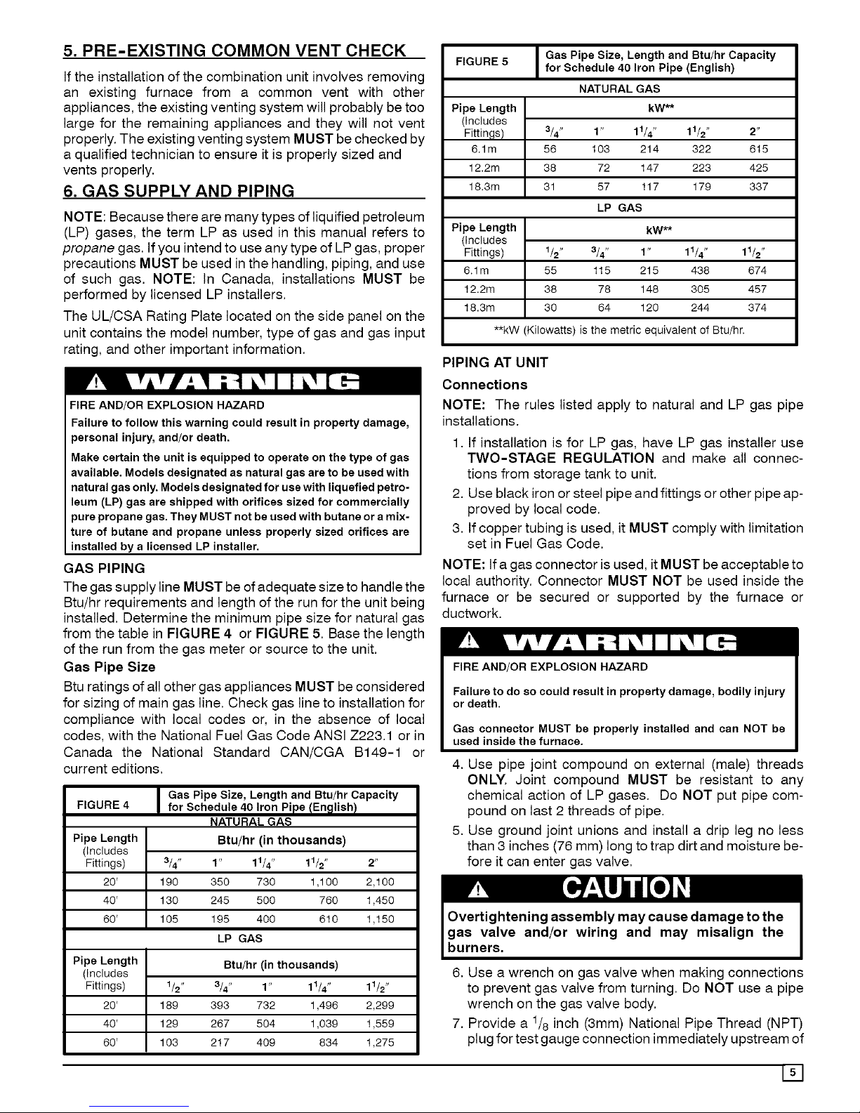
Gas Pipe Size, Length and Btu/hr Capacity
FIGURE 5
for Schedule 40 Iron Pipe (English)
Pipe Length
(Includes
Fittings)
6.1m
3/4" 2"
56 615
12.2m 38 425
18.3m 31 337
Pipe Length
(Includes
Fittings) 1/2" 11/2"
6.1m 55 674
12.2m 38 457
18.3m 30 374
**kW (Kilowatts) is the metric equivalent of Btu/hr.
NATURALGAS
kW**
1" 11/4" 11/2"
103 214 322
72 147 223
57 117 179
LP GAS
kW**
3/4" 1" 11/4"
115 215 438
78 148 305
64 120 244
PIPING AT UNIT
Connections
NOTE: The rules listed apply to natural and LP gas pipe
installations.
1. If installation is for LP gas, have LP gas installer use
TWO-STAGE REGULATION and make all connec-
tions from storage tank to unit.
2. Use black iron or steel pipe and fittings or other pipe ap-
proved by local code.
3. If copper tubing is used, it MUST comply with limitation
set in Fuel Gas Code.
NOTE: If a gas connector is used, it MUST be acceptable to
local authority. Connector MUST NOT be used inside the
furnace or be secured or supported by the furnace or
ductwork.
FIRE AND/OR EXPLOSION HAZARD
Failure to do so could result in property damage, bodily injury
or death.
Gas connector MUST be properly installed and can NOT be
used inside the furnace.
4. Use pipe joint compound on external (male) threads
ONLY. Joint compound MUST be resistant to any
chemical action of LP gases. Do NOT put pipe com-
pound on last 2 threads of pipe.
5. Use ground joint unions and install a drip leg no less
than 3 inches (76 mm) long to trap dirt and moisture be-
fore it can enter gas valve.
6. Use a wrench on gas valve when making connections
to prevent gas valve from turning. Do NOT use a pipe
wrench on the gas valve body.
7. Provide a 1/8 inch (3mm) National Pipe Thread (NPT)
plug for test gauge connection immediately upstream of
[]
Page 6

the gas supply connection to the furnace ifnone is sup-
plied with the gas valve of unit.
8. Install a manual shutoff valve and tighten all joints se-
curely.
9. Make sure pilot tube and burner orifices are checked for
leakage.
ORIFICES
Orifice Sizes
Orifice sizes MUST be matched to the heating value of the
gas (see FIGURE 6 AND TABLE 1 & 2). Check with your
gas supplier and the National Fuel Gas Code ANSI Z223.1.
NOTE: An LP Conversion Kit MUST be used for conversion
to LP gas.
TABLE 1 & 2: Equivalent Orifice Sizes at High Altitudes
NOTE: For elevations above 2000 feet (610 meters), the
Btu input rating MUST be reduced by 4% for each 1000 feet
(305 meters) above sea level, unless the gas supplier's
Btu/ft3 content has already been adjusted for altitude.
Check Table 1 & 2 for the proper orifice sizes.
FIGURE 6 Orifice Sizes
Gas Specific Btu/ft 3
Type Gravity (k J/L)
Natural 0.6 1000
Propane 1.53 2500
#Adjust pilot flame as needed
Pilot
Orifice
Sizes
,018#
,011#
Table 1 NATURAL GAS ORIFICE SIZING
MEAN ELEVATION FEET ABOVE SEA LEVEL
0to 2000 2001 to 4001 to 5001 to 6001 to 7001 to 8001 to 9001 to
4000 5000 6000 7000 8000 9000 10000
Orifice Kit Orifice Orifice Orifice Orifice Orifice Orifice Orifice
Gas Output Drill # Number Drill # Drill # Drill # Drill # Drill # Drill # Drill #
040, 060, 080 44 1172664 45 46 47 47 48 48 49
100 41 1098575 43 43 43 44 44 45 46
120, 140 42 1098575 43 43 44 44 45 46 47
NOTE: The orifice sizes in the chart above derate the input rate at 4% per 1000 feet above sea level for altitudes exceeding 2000 feet
above sea level. If converting from LP gas to Natural Gas at altitudes exceeding 2000 feet above sea level, a .018 pilot orifice (part #
503211 ) and gas valve conversion kit (part # 1147772) are required for conversion OR use kit # 1172664 plus the required orifice size #
shown in Table 1. Natural Gas data is based on 0.60 specific gravity, a heating value of 1030 Btu/Cu. Ft., and 3.5" W.C. manifold pressure.
For fuels with different specific gravity, consult the National Fuel Gas Code ANSI Z223. ! -2002/N FPA 54-2002 or National Standard of
Canada, Natural Gas and Propane installation Code CSA B149.1-00.
Table2 LP GASORIFICESIZING
MEANELEVATIONFEETABOVESEA LEVEL
0to2000 2001to4000 4001to 7000 7001to9000 9001to 10,000
Orifice Kit Orifice Kit Orifice Kit Orifice Kit Orifice Kit
GasOutput Drill # Number Drill # Number Drill # Number Drill # Number Drill # Number
040,060,080 55 1172663 55 1172663 56 1172665 56 1172665 57 1172666
100,120,140 54 1172662 55 1172663 55 1172663 56 1172665 56 1172665
NOTE: The orifice sizes in the chart above derate the input rate at 4% per 1000 feet above sea level for altitudes exceeding 2000 feet
above sea level. LP Gas data is based on 1.52 specific gravity, a heating value of 2500 Btu/Cu. Ft., and 10.0" W.C. manifold pressure. For
fuels with different specific gravity, consult the National Fue! Gas Code ANSI Z223.1-2002/NFPA 54-2002 or National Standard of
Canada, Natural Gas and Propane installation Code CSA B149.1-00.
Changing Orifices 2. Shut OFF electric power at unit disconnect or service
3,
4,
ELECTRICAL SHOCK, FIRE AND/OR EXPLOSION HAZARD
Failure to follow this warning could result in property dam-
age, personal injury, and/or death.
Shut off electric power at unit disconnect or service panel and
shut off gas at manual shut off valve before beginning the fol-
lowing procedure.
Changing orifices requires a qualified service technician.
1. Shut OFF gas at manual shut off valve.
panel. If unit is still running, allow 2.5 minutes after gas
shut off before turning off power.
Disconnect the wires from the gas valve and discon-
nect pilot tubing from valve.
Remove the four screws holding the manifold to the
manifold brackets.
5. Carefully remove the manifold with the gas valve at-
tached.
6. Remove the orifices from the manifold with a 7/16" box
end or socket wrench.
7. Check to be sure that the size of each orifice is correct
for the Btu input desired.
Page 7
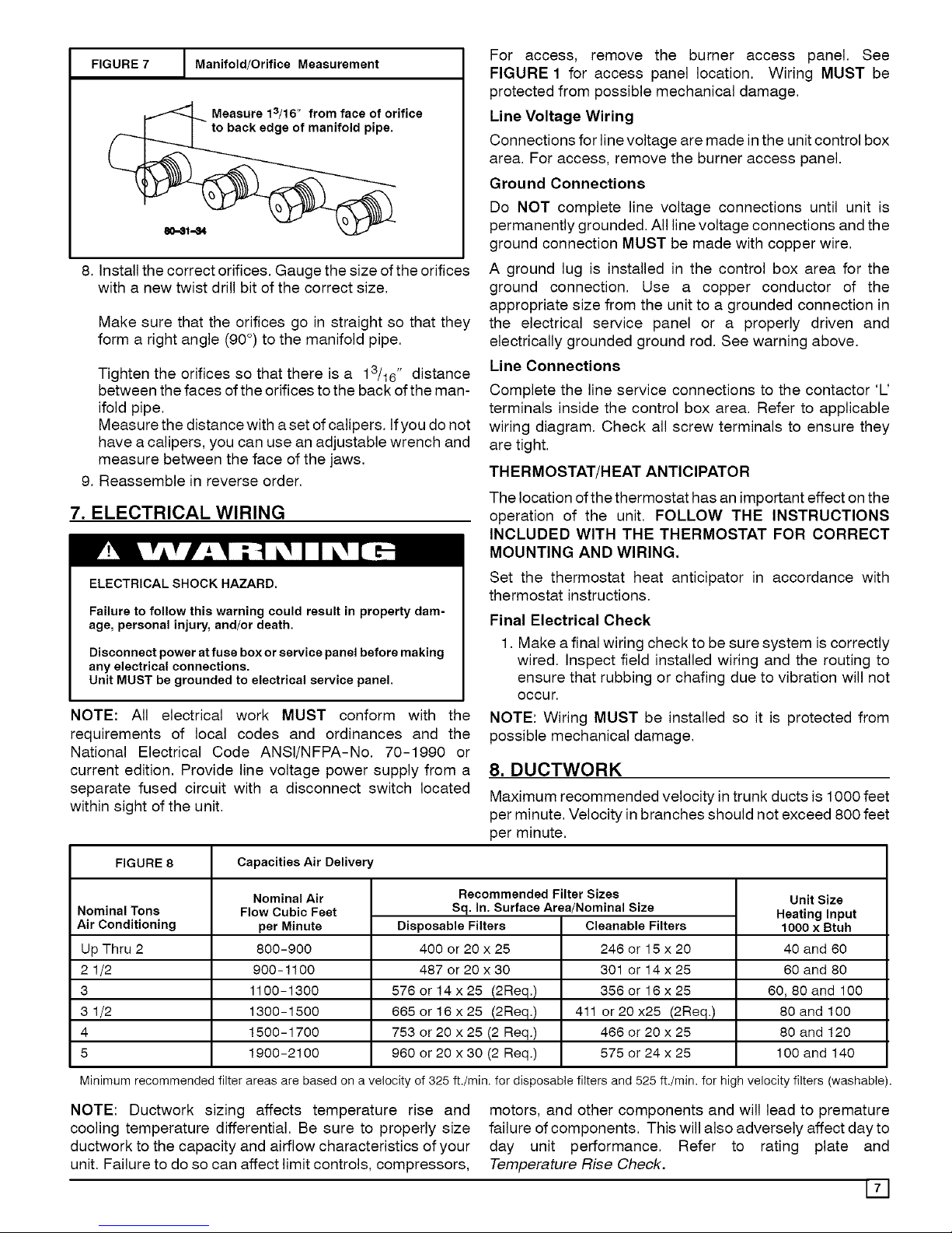
FIGURE 7
I Manifold/Orifice Measurement
Measure 13/16" from face of orifice
to back edge of manifold pipe.
8. Install the correct orifices. Gauge the size of the orifices
with a new twist drill bit of the correct size.
Make sure that the orifices go in straight so that they
form a right angle (90°) to the manifold pipe.
Tighten the orifices so that there is a 13/16" distance
between the faces of the orifices to the back of the man-
ifold pipe.
Measure the distance with a set of calipers. Ifyou do not
have a calipers, you can use an adjustable wrench and
measure between the face of the jaws.
9. Reassemble in reverse order.
7. ELECTRICAL WIRING
ELECTRICAL SHOCK HAZARD.
Failure to follow this warning could result in property dam-
age, personal injury, and/or death.
Disconnect power at fuse box or service panel before making
any electrical connections.
Unit MUST be grounded to electrical service panel.
NOTE: All electrical work MUST conform with the
requirements of local codes and ordinances and the
National Electrical Code ANSI/NFPA-No. 70-1990 or
current edition. Provide line voltage power supply from a
separate fused circuit with a disconnect switch located
within sight of the unit,
For access, remove the burner access panel. See
FIGURE 1 for access panel location. Wiring MUST be
protected from possible mechanical damage.
Line Voltage Wiring
Connections for line voltage are made inthe unit control box
area. For access, remove the burner access panel.
Ground Connections
Do NOT complete line voltage connections until unit is
permanently grounded. All line voltage connections and the
ground connection MUST be made with copper wire,
A ground lug is installed in the control box area for the
ground connection. Use a copper conductor of the
appropriate size from the unit to a grounded connection in
the electrical service panel or a properly driven and
electrically grounded ground rod. See warning above.
Line Connections
Complete the line service connections to the contactor 'L'
terminals inside the control box area. Refer to applicable
wiring diagram. Check all screw terminals to ensure they
are tight.
THERMOSTAT/HEAT ANTICIPATOR
The location ofthe thermostat has an important effect on the
operation of the unit. FOLLOW THE INSTRUCTIONS
INCLUDED WITH THE THERMOSTAT FOR CORRECT
MOUNTING AND WIRING.
Set the thermostat heat anticipator in accordance with
thermostat instructions.
Final Electrical Check
1, Make a final wiring check to be sure system is correctly
wired. Inspect field installed wiring and the routing to
ensure that rubbing or chafing due to vibration will not
occur.
NOTE: Wiring MUST be installed so it is protected from
possible mechanical damage.
8. DUCTWORK
Maximum recommended velocity in trunk ducts is 1000 feet
per minute. Velocity in branches should not exceed 800 feet
per minute,
FIGURE 8 Capacities Air Delivery
Nominal Tons
Air Conditioning
Up Thru 2
2 1/2
3
3 1/2
4
5
Nominal Air
Flow Cubic Feet
per Minute
800-900
900-1100
1100-1300
1300-1500
1500-1700
1900-2100
Recommended Filter Sizes
Sq. In. Surface Area/Nominal Size
Disposable Filters Cleanable Filters
400 or 20x25 246 or15x20
487or20x30 301 or14x25
576 or 14 x 25 (2Req.)
665 or 16 x 25 (2Req.)
753 or 20 x 25 (2 Req.)
960 or 20 x 30 (2 Req.)
356or16x25
411 or20x25 (2Req.)
466 or 20 x 25
575 or 24 x 25
UnitSize
Heatinglnput
1000 x Btuh
40 and 60
60 and 80
60,80 and 100
80 and 100
80 and 120
100 and 140
Minimum recommended filter areas are based on a velocity of 325 ft./min, for disposable filters and 525 ft./min, for high velocity filters (washable).
NOTE: Ductwork sizing affects temperature rise and
cooling temperature differential. Be sure to properly size
ductwork to the capacity and airflow characteristics of your
unit. Failure to do so can affect limit controls, compressors,
motors, and other components and will lead to premature
failure of components. This will also adversely affect dayto
day unit performance. Refer to rating plate and
Temperature Rise Check.
171
Page 8

Combustion Blower Pipe Installation
Remove the combustion blower pipe from the right corner of
burner compartment and position the end of the pipe with
the screw hole over the opening of the combustion blower.
The other end of the pipe should now be aligned through the
opening in the side panel of unit. The pipe should slightly
protude through the opening in the side panel.
Remove (1) chisle pointed #10 screw (self drilling) taped to
the vent cap. Position the screw to the hole in the pipe and
drill through the combustion blower outlet securing the pipe
to the combustion blower.
Ductwork Insulation
Ductwork installed outdoors should have a minimum of 2"
fiberglass insulation and a weatherproof vapor barrier. It
should be protected against damage. Caulking and
flashings, or other means adequate to provide a permanent
weather seal, should be used.
Ductwork installed in attics or other areas exposed to
outside temperatures should be installed with a minimum of
2" fiberglass insulation and have an indoor type vapor
barrier.
Ductwork Connections
The use of flexible, non-combustible connectors between
main trunk ducts and supply and return air plenums is
recommended to minimize vibration transmission.
NOTE: Connect supply and return air plenums to unit in a
manner that will allow the top of the unit to be removed
without removing plenums. Plenums MUST be individually
sealed to unit casing with ducts terminating inside structure.
FILTERS
All return air MUST pass through a filter before entering the
unit. An electronic air cleaner, optional filter racks, or other
accessible filter arrangement MUST be installed in the
return air ductwork. Minimum recommended filter areas
are listed in FIGURE 8 and are based on a velocity of 325
ft/min for disposable filters and 525 ft/min for high velocity
filters (washable).
CAUTION
DO NOT OPERATE THE UNIT WITHOUT A FILTER.
9. START-UP PROCEDURES
FIRE AND/OR EXPLOSION HAZARD
Failure to follow this warning could result in property dam-
age, personal injury, and/or death.
Do NOT attempt to light the pilot or burner with a match or
flame of any kind.
CHECK BEFORE STARTING
1. Check that the blower motor speed terminal block is
running the correct heating and cooling speeds.
2. Check to see that clean, properly sized air filters are
installed.
3. Replace all service access panels.
Reverse Rotation (Scroll Compressors Only)
Three phase scroll compressor equipped units CAN run in
reverse if improperly wired. If the compressor makes an
unusually loud noise, or if high and low side pressures are
nearly identical, this indicates reverse rotation. To correct,
reverse any two wires at line voltage connections ONLY. Do
NOT re-wire any circuits inside the unit to attempt
correction of reverse rotation.
Manifold Gas Pressure Adjustment
NOTE: Make adjustment to manifold pressure with burners
operating.
FIRE OR EXPLOSION HAZARD,
Failure to properly seal duct could result in personal injury
and/or death.
Turn OFF gas at shut off before connecting U-tube ma-
nometer.
FIGURE 9
Inlet Pressure
Tap (Hidden)
Honeywell Gas Valve
On/Off Switch
Ignitor
Wiring
Harness
INLET .Control
Wiring
\ Harness
\
1<_ Outlet
Pressure
Tap
Pilot Adjustment
OUTLET
GAS PRESSURES
1. Do NOT allow gas supply pressure to fall below the
listed minimums. Doing so will decrease input to fur-
nace. Refer to FIGURE 10 for gas supply pressures.
2. Gas input MUST NOT exceed rated input shown on rat-
ing plate.
3. Do NOT allow pressures to exceed the maximum limits
as listed in FIGURE 10.
Page 9

FIGURE 10 Gas Pressures
Natural Gas LP Gas
Minimum 4.5"W.C. (1120 Pa) 11" W.C. (2740 Pa)
Inlet
Recommended 7" W.C. (1740 Pa) 11" W.C. (2740 Pa)
Inlet
Maximum 13" W.C. (3230 Pa) 13" W.C. (3230 Pa)
Inlet
Manifold 3.5" W.C. (870 Pa) 10" W.C. (2490 Pa)
Pressure
Manifold Pressures
Manifold pressures are covered in the startup procedure
section. Refer to Chapter 9 Start-Up Procedures.
1. With gas OFE Connect U-Tube manometer to tapped
opening on gas valve. Use manometer with a 0 to 12
inches water column range.
FIGURE 11 Manifold Pressure Settings
Gas Type Manifold Pressure
Natural 3.5 Inches Water Column (870 Pa)
Propane 10 Inches Water Column (2490 Pa)
2. Turn gas ON and remove adjustment screw cover on
gas valve. Turn counterclockwise to decrease pressure
and clockwise to increase.
NOTE: Adjustment screw cover MUST be placed on gas
valve before reading manifold pressure and operating
furnace.
FIRE AND/OR EXPLOSION HAZARD
Failure to properly set input pressure could result in prop-
erty damage, personal injury and/or death.
Do NOT adjust manifold pressure more than -+0.3 inches
water column to obtain rated input.
3. Set pressure to value shown in FIGURE 11, + 0.07kPa
(0.3 inches) water column. Pressure is also listed on
furnace rating plate. In NO case should final manifold
pressure vary more than + 0.07kPa (0.3 inches) water
column.
CIRCULATING AIR BLOWER
Check the unit's operation as outlined in the following
instructions. If any unusual sparking, odors or unusual
noises are encountered, shut off electric power
immediately. Recheck for wiring errors, or obstructions in or
near blower motors.
1. Set thermostat Heat-Cool selector to OFE
2. Set thermostat fan switch to AUTO.
3. Turn electric power ON. Nothing should start running.
4. Turn manual gas valve ON.
5. Turn gas control valve ON.
6. Set thermostat fan switch to ON.
7. Reset thermostat fan switch to AUTO.
HEATING START-UP PROCEDURE
1. Adjust thermostat setting above room temperature and
set thermostat selector to HEAT. The combustion air
blower should come ON.
2. The ignitor should begin to glow and pilot flame should
light. Refer to Lighting/Operating Instructions label lo-
cated on Burner Access Panel of unit.
NOTE: On a call for heat the ignitor and pilot valve will
remain energized until a flame is detected by the flame
sensor. It may take several minutes to purge the air out of
the gas lines at initial start-up of the unit.
3. Once the flame sensor detects that a flame is present,
the hot surface ignitor will de-energize and the main
burners will light from the pilot.
4.30 seconds after the burners light, the circulating blow-
er should begin to run.
FIRE AND/OR EXPLOSION HAZARD
Failure to follow this warning could result in property dam-
age, personal injury, and/or death.
Do NOT attempt to light the pilot or burner with a match or
flame of any kind.
Temperature Rise Check
NOTE: Air temperature rise is the temperature difference
between supply and return air. With a properly designed
distribution system, the proper amount of temperature rise
will normally be obtained when the unit is operating at rated
input with the recommended blower speed.
1. The temperature rise must be within the specifications
marked on the unit rating plate.
To check the temperature rise through the unit, place ther-
mometers in the supply and return air ducts as close to the
unit as possible.
Open ALL registers and duct dampers. Operate unit AT
LEAST 15 minutes before taking readings,
If the correct amount of temperature rise is not obtained
when operating on the recommended blower speed, it may
be necessary to change the blower speed. A faster blower
speed will decrease the temperature rise. A slower blower
speed will increase the temperature rise.
NOTE: The blower speed MUST be set to give the correct
air temperature rise through the furnace as marked on the
rating plate. See FIGURE 13 for more information.
2. After 15 minutes of operation check the limit control
function by blocking the
return air grille(s).
After several minutes the main burners and pilot should
go OFF. The circulating air blower should continue to
run.
Remove air restrictions. Pilot and main burners should
relight after a cool down period of a few minutes.
3. Adjust the thermostat setting below room temperature.
191
Page 10

Pilot and main burners and combustion air blower
should go OFF
The circulating air blower should continue to run for 60,
100,140 or 180 seconds. This time is adjustable. See
FIGURE 12 for more information.
4. Set thermostat Heat-Cool selector to OFF.
FAN CONTROLCHECK
FIGURE 12 Fan Delay DIP Switch Settings
Cooling Off Delay : 30 Sec.
Coolin ON
Delay
I
0 30
Seconds
Heat Off Delay
60 100
Seconds Seconds
140
Seconds
180
Seconds
Heat On Delay
[][]1'1
30 sec
The Fan Control has adjustable settings for the circulating
air blower to delay it "ON" and "OFF".
1. The "ON" delay is factory pre-set at 30 seconds. It can
be adjusted to 60 seconds.
2. The "OFF" delay is factory preset at 140 seconds. It
can be adjusted to 60, 1O0 and 180 seconds, respec-
tively.
Refer to FIGURE 12 for proper DIP switch settings.
3. Operate the furnace and ensure that the blower turns
ON and OFF at the appropriate time to provide the de-
sired comfort level.
SPEED TAPS
After determining necessary CFM and speed tap data,
follow the steps below to change speeds.
1. Refer to FIGURE 13 and locate the speed tap block on
blower motor.
2. The yellow lead MUST always be connected to the
speed tap block at the common quick connect terminal.
The terminal is identified as COM. Also, this is the only
lead which is 3/16" wide. All other quick connects are
1/4"wide.
3. If it has been determined that cooling and heating
speeds are needed on the same speed tap, remove the
red heating lead from the speed tap block and connect it
to the insulated male terminal on the black cooling lead.
Then place the insulated black female quick connect to
the required speed tap.
CONTINUOUS FAN OPERATION
An optional terminal may be provided on the electronic fan
control located in the electrical control box area for
operation of the continuous fan option. This connection is
intended for the low speed motor tap, and has a lower
contact rating (8 amps) than the heat and cool taps. When
the low speed blower lead is connected to this terminal, this
will provide low speed blower operation whenever the other
two speeds (Heat or Cool) are not energized.
Thoroughly check the system after modification to ensure
the proper operation of the circulating air blower in all
modes of operation.
Separate Speed Selections for Heat, Cool and
Continuous Fan
Connect low speed lead from circulating motor to the
"Cont" terminal at the electronic fan control. The
appropriate motor leads should already be connected to the
"Heat" and "Cool" terminals.
Note: See next section "Heating or Cooling and
Continuous Blower Speed the Same" if low speed is
required for heating to obtain desired temperature rise.
Heating or Cooling and Continuous Blower Speed
the Same
If is necessary to operate the heating or cooling speed and
continuous blower speed using the same blower speed,
connect a jumper between the "Heat" and "Cont" terminals
on the Fan Timer Board.
Note: There should be only ONE motor lead going to the
"Heat" and "Cont" terminals.
COOLING
1. Turn electric power OFF
2. Set thermostat Heat-Cool select to COOL.
3. Adjust thermostat setting to below room temperature.
4. Turn power ON, for approximately one minute, then
OFE During power application check the following:
a. Contactor - Contacts Closing
b. Compressor - ON
c. Condenser fan motor - ON
d. Circulating Air Blower - ON 0 or 30 second delay
5. Turn power OFE check the following:
a. Contactor contacts opening.
b. Compressor - OFF
c. Condenser fan motor - OFF
d. Circulating blower - OFF after a 30 second delay.
Page 11

FIGURE 13 I Blower Motor Speed Taps (3-Speed and 4-Speed Motors)
I BE SURE TO CHECK BLOWER MOTOR I
SPEED DATA IN UNITS
TECHNICAL INFORMATION LABEL
ON THE UNIT
/
,/
/
YELLO_L
10. OPERATION
f
Once the thermostat issatisfied, the fan control will operate
the blower for 30 additional seconds.
11. MAINTENANCE
ELECTRICAL SHOCK HAZARD.
Failure to follow this warning could result in property dam-
age, personal injury, and/or death.
Turn off electric power supply at disconnect switch or service
panel before removing any access or service panel from unit.
COMBUSTION/INDOOR FAN CONTROL
All functions of the combustion and indoor blower are
controlled by the fan control module.
On a call for heat:
The fan control energizes the combustion blower. Once the
combustion air proving switch closes, the ignition sequence
begins. The fan control will sense when the main operator
of gas valve has been energized thereby firing the burners
and starting the "delay on" timing sequence of the indoor
blower.
NOTE: Ifthe control senses that one of the safety limits has
opened, the combustion and indoor fans will operate until
the limit resets.
On a call for cooling:
The fan control starts the indoor blower at 0 or 30 seconds.
MONTHLY MAINTENANCE AND INSPECTION
CHECKS
Air Filters
CAUTION
Do NOT operate without air filters.
Inspect filters at least monthly and replace or clean as
required. Washable filters may be cleaned by soaking in
mild detergent and rinsing with cold water. Replace filters
with the arrows on the side pointing in the direction of air
flow. Dirty filters are the most common cause of inadequate
heating or cooling performance, and of compressor
failures.
HEATING SEASON CHECKS (MONTHLY)
Pilot Flame
While the main burner is on, the flame should envelop the
upper part of the flame sensor.
Main Burner Flame
Flames should be stable and solid blue, (dust may cause
orange tips or they may have wisps of yellow, but they
MUST not have solid yellow tips). They should extend
directly into the heat exchanger tubes and the turbulators
Illl
Page 12

should glow orange (after about five minutes of operation).
Main burner flame should be inspected monthly.
FIGURE 14
Normal Flame
I
Turbulator will glow
orange when hot.
Flame should be
stable and solid
blue.
Using a light and mirror (as required) inspect the inside of
the vent hood and the inlet air opening in the burner
compartment. Look for soot and severe rust or corrosion
and any obstructions due to leaves, spiderwebs, etc. Clean
as required.
COOLING SEASON CHECKS (MONTHLY)
Condenser Coil
Keep the condenser inlet and outlet area clean and free of
leaves, grass clippings or other debris. Grass should be
kept short in front of the condenser inlet. Shrubbery MUST
be trimmed back so it is no closer than 30 inches to unit.
Condensate Drain
Check for condensate drainage. Clean as required.
ANNUAL MAINTENANCE AND INSPECTION
ELECTRICAL SHOCK HAZARD,
Failure to follow this warning could result in property dam-
age, personal injury, and/or death.
Turn off electric power supply at disconnect switch or service
panel before removing any access or service panel from unit.
The annual inspection should include lubrication and
cleaning as required to ensure efficient operation of the unit.
To simplify access, remove all access panels and the top
from the unit if possible.
Condenser Fan Motor
Oil the condenser fan motor after five years of operation and
every five years thereafter, if applicable,
VENT ASSEMBLY
BURN HAZARD.
Failure to follow this warning could result in property damage
or personal injury.
Flue cover may be hot! Allow adequate time for flue cover to
cool
Use SAE 10W30 motor oil. To oil, remove the hole plugs
from the motor end bells and add several drops
(approximately 1/2 teaspoonful) of oil with a squeeze type,
flexible tube oiler. Replace hole plugs after oiling. Do not
over oil,
Clean the surrounding area and the condenser and
evaporator coils. Use caution to avoid damage to coil fins,
BLOWER MOTOR ACCESS
Refer to Figure 15 for a view of blower motor and
compartment.
1. Remove the blower access panel
2. Remove the three screws securing the blower motor
housing. If unit has a support bracket, remove the two
screws securing the bracket.
3. Remove the two red wires attached to the limit switch-
and remove the limit switch.
Motor removal and replacement
This method is required to replace or repair blower wheel,
blower housing, or any unreachable components behind
blower assembly.
1. Remove all screws around rim of unit top, (except
screws which are inaccessible because of proximity to
structure).
2. Raise unit top at corner of unit closest to blower at least
2" and place a sturdy brace at least 2" thick between top
and unit corner. See FIGURE 15. A 2X4 piece of wood
is ideal for this.
3. Disconnect all wires from housing and slide housing out
of unit. Reverse this process to reinstall.
Blower Access Showing Lid
FIGURE 15 Propped with 2X4
Page 13

Circulating Air Blower
Visually inspect the blower wheel for accumulations of dirt
or lint. Clean the compartment and the blower wheel. If
accumulation is excessive on blower wheel, or does not
easily remove, it will be necessary to remove the blower
assembly.
Oil the blower motor, if applicable, by adding 1/2teaspoonful
(lcc) of SAE 10W30 to each motor bearing. The blower
motor should be oiled after five years of operation and every
five years thereafter.
Do not use 3 in 1 oil, penetrating oil, WD40 or
similar oils to oil motor bearings.
Burners / Heat Exchangers / Flue Gas Passages
To inspect the burners, heat exchanger and interior flue gas
passages, use a light and small mirror on an extension
handle.
Check the exterior of the heat exchanger and the interior
flue gas passages for any evidence of deterioration due to
corrosion, cracking or other causes. If signs of scaling or
sooting exist, remove the burners and clean the heat
exchanger, as required.
INSPECTION AND CLEANING OF BURNER
ASSEMBLY/HEAT EXCHANGERS/FLUE GAS
PASSAGES
For Qualified Service Technician Only
See FIGURE 16 for identification of parts.
1. Disconnect electrical power to unit.
2. Turn OFF gas at manual shut off valve.
3. Remove burner access panel.
4. Remove the vent assembly flue pipe.
5. Disconnect gas pipe at union.
6. Disconnect wires from gas valve, note connections.
7. Remove screws that secure the flame shield and re-
move gas control valve, manifold and burners as an
assembly.
8. Remove collector box, injector plate, and restrictor
plate, including gaskets.
9. Hold the burner assembly vertically and lightly tap it
against a wood block. Clean also with a stiff brush. Se-
vere cases of lint clogging may require washing the
burners in hot water.
10. Clean flue gas passages by using small brushes and a
vacuum cleaner. It may be necessary to fabricate han-
dle extensions for the brushes to reach the areas that
require cleaning. Reinspect after cleaning and replace
the heat exchanger if defective.
11. Reinstall parts and gaskets in reverse order. On spark
to pilot models check the spark gap. 1/8inch is required
between the igniter and pilot hood.
12. Turn gas on and check for leaks.
13. Install all access panels, turn power on and check for
normal operation.
1131
Page 14

FIGURE 16 Access to Burners
Manifold
I Gas Valve
Pressure Switch
I Fan Timer Board
0
I Pilot Assembly I
Flame Shield I
I
I
80-31-31
I Ro!!out Switch I
Pilot Assy, (Hidden) I
Collector Box I
Ground Lug I
Page 15

E
R GGING NSTRUCT ONS __
rs,_uREToro._owT_SE,.STROCT,O_S
WA_L[/0 c_ RESo_I._PROPERTY'D_G_-.
- ALL PANELS MUST BE IN PLACE WHEN RIGGING AND LIFTING.
- HOOK RIGGING SHACKLES THROUGH HOLES IN BASE RAIL, AS SHOWN IN DETAIL-A.
- USE SPREADER BARS, WHEN RIGGING, TO PREVENT UNIT DAMAGE.
- BE SURE RIGGING AND SHACKLES ARE SUFFICIENT TO HANDLE WEIGHT LISTED BELOW.
_ _SPREADER
111
BARS
DETAIL-A
_OR_
CABINET
SMALL
LARGE
MAX.
IN
52.00
75.00
LENGTH
MM
1219
1854
MAX.
IN
48.OO
48.OO
WIDTH
MM
1219
1219
MAX.
IN
58.00
58.00
HEIGHT
MM
965
965
MAX. WEIGHT
LB KG
500 227
900 409
-11
r-
m,
,,,1
c
o
m,
o
 Loading...