

Page 1
Installation Instructions
PGF, PGC, PGS, GPFM, GPCM, GPSM
!
COMBINATION UNITS
GAS HEAT / ELECTRIC COOL
11/2 to 5 TON
Printed in U.S.A.
462 01 1003 01 1-6-04
Page 2
1. Safety Labelinq and Siqnal Words
Danger,Warning and Caution
The signal words DANGER, WARNING and CAUTION are
used to identify levels of hazard seriousness. The signal
word DANGER is only used on product labels to signify an
immediate hazard. The signal words WARNING and
CAUTION will be used on product labels and throughout
this manual and other manuals that may apply to the
product.
Signal Words
DANGER - Immediate hazards which WILL result in
severe personal injury or death.
WARNING - Hazards or unsafe practices which COULD
result in severe personal injury or death.
CAUTION - Hazards or unsafe practices which COULD
result in minor personal injury or product or property
damage.
Signal Words in Manuals
The signal word WARNING is used throughout this manual
in the following manner:
Danger Label
White lettering on a black background except the word
DANGER which is white with a red background,
Warning Label
White lettering on a black background except the word
WARNING which is black with an orange background,
Caution Label
White lettering on a black background except the word
CAUTION which is black with a yellow background,
The signal word CAUTION is used throughout this manual
in the following manner:
CAUTION
Product Labeling
Signal words are used in combination with colors and/or
pictures on product labels. Following are examples of
product labels with explanations of the colors used.
J2J 462 01 1003 01
Page 3
[IJ_lli I]I LV4:1l [.,-'][I]l [.,-_
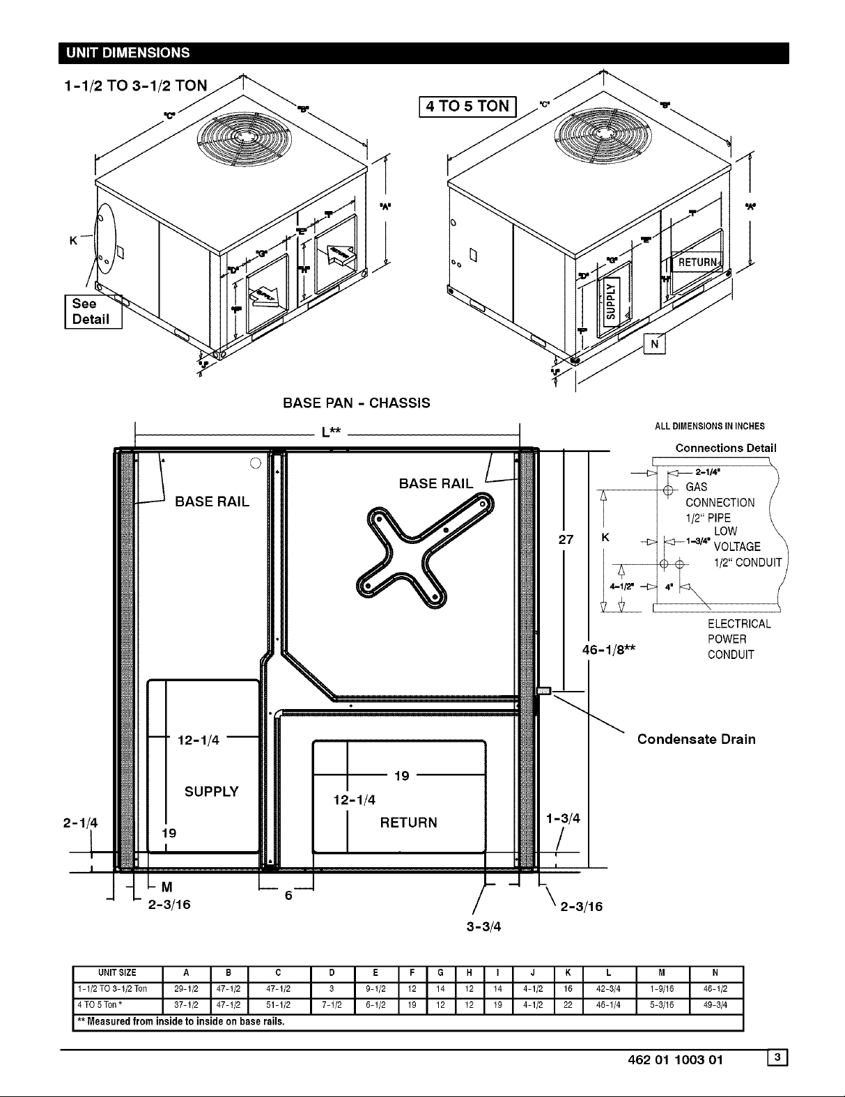
1-1/2 TO 3-1/2 TON
BASE RAIL
BASE PAN - CHASSIS
L_-k
©
[ 4 TO 5 TON
I/lliI "A"
ALL DIMENSIONS IN INCHES
Connections Detail
BASE RAIL
AS /
ONNECTtON (
1/2 \
<F-1-3/4" VOLTAGE _
12-1/4 --
191 SUPPLY _
I
M
2-3/16
UNITSIZE A B C
1-112TO3-1/2 Ton 29-1/2 47-1/2 47-1/2
4 TO5 Ton* 37-1/2 47-1/2 51-1/2
** Measured from inside to inside on base rails.
46 - 1/8"*
Condensate Drain
19
12-1/4
RETURN
2-3/16
3-3/4
D E F G H I J K L M
3 9-1/2 12 14 12 14 4-1/2 16 42-3/4 1-9/16
7-1/2 5-1/2 19 12 12 19 4-1/2 22 46-1/4 5-3/16
ELECTRICAL
POWER
CONDUIT
N
46-1/2
49-3/4
46201100301 131
Page 4
3. SAFE INSTALLATION REQUIREMENTS
Installation or repairs made by unqualified persons can result
in hazards to you and others. Installation MUST conform with
local building codes or, in the absence of local codes, with the
ANSI Z223.1 and the National Electrical Code NFPA70-1990 or
in Canada the National Standard CAN/CGA B149-1 and CSA
C.22.1 - Canadian Electrical Code Part 1.
The information contained in this manual is intended for use
by a qualified service technician familiar with safety proce-
dures and equipped with the proper tools and test instru-
ments.
Failure to carefully read and follow all instructions in this
manual can result in furnace malfunction, property damage,
personal injury and/or death.
• Do NOT use this furnace as a construction heater.
• Use only the Type of gas approved for this furnace (See
Rating Plate).
• Do NOT use open flame to test for gas leak.
• Seal supply and return air ducts.
• Check to see that filters are installed correctly and are
the proper type an size.
NOTE: It is the personal responsibility and obligation of the
customer to contact a qualified installer to ensure that the
installation is adequate and conforms to governing codes
and ordinances.
CAUTION
It is recommended that a qualified service technician
check the heat exchanger integrity every two (2) years,
after the first four (4) years of operation.
4. LOCATING THE UNIT
NOTE: Units with available filter racks ( 3-1/2 to 5 ton), need
a 26" minimum clearance at side of unit for removal of
filters. See chart below if unit is going to be placed near
combustible construction or materials.
While minimum clearances are acceptable for safety
reasons, they may not allow adequate air circulation around
the unit for proper operation in the cooling mode. Whenever
possible, it is desirable to allow additional clearance,
especially around the condenser inlet and discharge
openings.
Do NOT install the unit in a location that will permit
discharged air from the condenser to recirculate to the
condenser inlet.
CAUTION
Do NOT operate unit in a corrosive atmosphere con-
taining chlorine, fluorine, or any other corrosive
chemicals.
Minimum Clearances to Combustible Construction
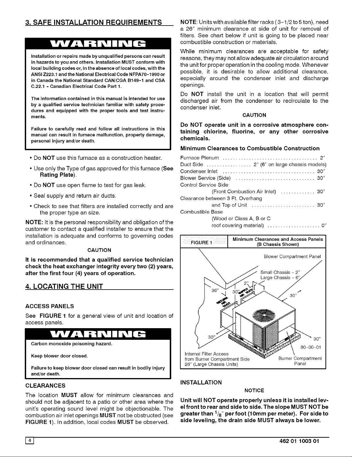
Furnace Plenum .................................... 2"
Duct Side ................. 2" (6" on large chassis models)
Condenser Inlet ................................... 30"
Blower Service (Side) .............................. 30"
Control Service Side
(Front Combustion Air Inlet) ............. 30"
Clearance between 3 Ft. Overhang
and Top of Unit ........................ 30"
Combustible Base
(Wood or Class A, B or C
roof covering material) .................... 0"
FIGURE i Minimum Clearances(BChassisandshown)ACcessPanels
Blower Compartment Panel
Large Chassis
ACCESS PANELS
See FIGURE 1 for a general view of unit and location of
access panels.
Carbon monoxide poisoning hazard.
Keep blower door closed.
Failure to keep blower door closed can result in bodily injury
and/or death.
CLEARANCES
Internal Filter Access
from Burner Compartment Side
26" (Large Chassis Units)
INSTALLATION
Burner Compartment
NOTICE
80-00-01
Panel
The location MUST allow for minimum clearances and
should not be adjacent to a patio or other area where the
unit's operating sound level might be objectionable. The
combustion air inlet openings MUST not be obstructed (see
FIGURE 1). In addition, local codes MUST be observed.
141 462 01 1003 01
Unit will NOT operate properly unless it is installed lev-
el front to rear and side to side. The slope MUST NOT be
greater than 1/8"per foot (10mm per meter). For side to
side leveling, the drain side MUST always be lower.
80 _
Page 5

Ground Level Installation
Ground level platform requirements:
- The unit MUST be situated to provide safe access for
servicing.
Platform may be made of either concrete or pressure
treated wood and MUST be level and strong enough to
support unit weight.
Position platform separate from building foundation.
Install in well-drained area, with top surface of platform
above grade level.
Platform must be high enough to allow for proper con-
densate trap installation and drainage. See FIGURE 3
and associated text for more information about conden-
sate drainage.
Rooftop Installation
Rooftop platform requirements:
- The unit MUST be situated to provide safe access for
servicing.
- The existing roof structure MUST be adequate to sup-
port the weight of the unit or the roof MUST be
reinforced.
Check the weight of the unit in relation to the roof struc-
ture and local building codes or ordinances and
reinforce roof structure if necessary. See the last page
of this manual for unit weights.
- Support for the unit MUST be level and strong enough
to carry unit weight. The support may consist of a plat-
form or a combination of platform and roof beams or
curb.
- See Hoisting section for hoisting instructions.
HOISTING
NOTE: All access panels MUST be secured in place before
hoisting.
The unit should be hoisted with two lifting slings. Attach the
slings to rigging shackles that have been hooked through
holes in the base rail.
Two spreader bars MUST be placed on top of the unit to
protect the unit from damage from the pressure exerted by
the slings. Make sure that all equipment is adequate to
handle the weight of the unit and that the slings will not allow
the unit to shift.
Refer to FIGURE 17 on the back cover of this manual for
illustrated rigging instructions and weight chart.
DOWNFLOW CONVERSION
NOTE: In downflow applications with roof curbs or jack
stands, the center rail under the unit must be removed. The
center rail is attached to the base rail with screws.
These units are adaptable to downflow use. To convert to
downflow use, follow these steps:
1. Remove the blockoff plates found in the return air
compartment and the supply air compartment.
NOTE: Blockoff plate in the supply air compartment only
contains one screw. If reinstalling plate, back part of plate
MUST fit into mating dimples on flange. To reinstall, slant
plate into dimples, then put plate into position and fasten
with screw.
2. Install the removed plates on the horizontal return and
supply air openings.
3. Install roof curb on the building. Be sure to follow all di-
rections included with curb and all applicable building
codes in your installation.
Heating Vent Assembly
Refer to FIGURE 2 and assemble as shown.
FIGURE 2 Heating Vent Assembly
Atta(_t?with 2 screws
Heen_ingi__ _
CAUTION
DO NOT OPERATE THE UNIT WITHOUT THE VENT AS-
SEMBLY INSTALLED
Condensate Drain
The condensate drain outlet is a 3/4" (19.1 mm) female PVC
connection located at the bottom on the left hand side (see
FIGURE 3).
The circulating blower creates a negative pressure on the
condensate drain line that can prevent the condensate from
draining properly. To combat this negative pressure, a field
supplied condensate trap that will allow a standing column
of water of at least 2" (50.8mm) MUST be installed. Top of
outlet from trap MUST be at least 1" (25.4mm) below top of
outlet from unit. Install the trap as near to the unit as
possible for proper drainage,
A3/4" (19.1mm) drain line MUST be installed if required by
local codes or if location of unit requires it. Run the drain line
to an open drain or other suitable disposal point.
Flue Pipe
3 | Condensateora ninformation*
$
3/4" (19,1mm)
Female PVC
Fitting X
(25.4mm)
80-31-32
(
2" (50.8mm)
3/4" (19.1mm)
Drain Line
* Condensate trap MUST be installed.
462 01 1003 01 151
Page 6
5. PRE-EXISTING COMMON VENT CHECK
If the installation of the combination unit involves removing
an existing furnace from a common vent with other
appliances, the existing venting system will probably be too
large for the remaining appliances and they will not vent
properly. The existing venting system MUST be checked by
a qualified technician to ensure it is properly sized and
vents properly.
6. GAS SUPPLY AND PIPING
NOTE: Because there are many types of liquified petroleum
(LP) gases, the term LP as used in this manual refers to
propane gas. If you intend to use any type of LP gas, proper
precautions MUST be used in the handling, piping, and use
of such gas. NOTE: In Canada, installations MUST be
performed by licensed LP installers.
The UL/CSA Rating Plate located on the side panel on the
unit contains the model number, type of gas and gas input
rating, and other important information.
Fire and/or explosion hazard.
Make certain the unit is equippedto operate onthe type of gas
available. Models designated as natural gas are to be usedwith
naturalgas only.Modelsdesignated for use with liquefiedpetro-
leum (LP) gas are shipped with orifices sized for commercially
pure propanegas. They MUST not beusedwith butane or a mix-
ture of butane and propane unless properly sized orifices are
installed by a licensed LP installer.
Failure to follow this warning can result in property damage,
_ersonal injury,and/or death.
GAS PIPING
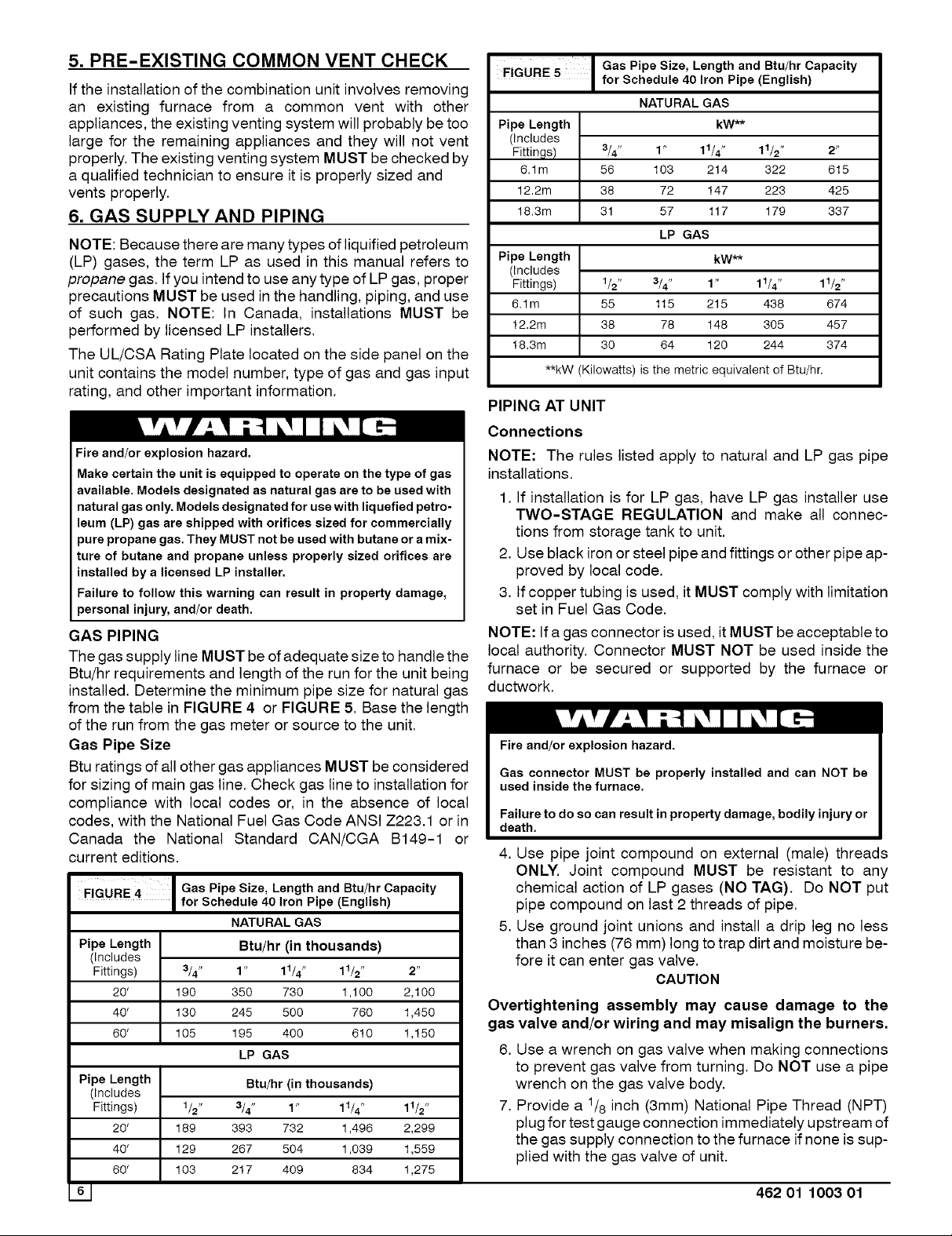
The gas supply line MUST be of adequate size to handle the
Btu/hr requirements and length of the run for the unit being
installed. Determine the minimum pipe size for natural gas
from the table in FIGURE 4 or FIGURE 5. Base the length
of the run from the gas meter or source to the unit.
Gas Pipe Size
Btu ratings of all other gas appliances MUST be considered
for sizing of main gas line. Check gas line to installation for
compliance with local codes or, in the absence of local
codes, with the National Fuel Gas Code ANSI Z223.1 or in
Canada the National Standard CAN/CGA B149-1 or
current editions.
FIGURE 4
Pipe Length Btu/hr (in thousands)
(Includes
Fittings) 3/4" 1" 11/4" 11/2" 2"
20' 190 350 730 1,100 2,100
40' 130 245 500 760 1,450
60 ' 105 195 400 610 1,150
Pipe Length Btu/hr (in thousands)
(Includes
Fittings) 1/2" 3/4" 1" 11/4"
20' 189 393 732 1,496
40' 129 267 504 1,039
60' 103 217 409 834
Gas Pipe Size, Length and Btu/hr Capacity
for Schedule 40 Iron Pipe (English)
NATURAL GAS
LP GAS
11/2"
2,299
1,559
1,275
FIGURE 5
Pipe Length
(Includes
Fittings)
6.1m
12.2m 38 425
18.3m 31 337
Pipe Length kW**
(Includes
Fittings) 1/2" 3/4" 1 " 11/4 " 11/2"
6.1m 55 115 215 438 674
12.2m 38 78 148 305 457
18.3m 30 64 120 244 374
**kW (Kilowatts) is the metric equivalent of Btu/hr.
Gas Pipe Size, Length and Btu/hr Capacity
for Schedule 40 Iron Pipe (English)
NATURAL GAS
kW**
3/4" 2"
56 615
1" 11/4" 11/2"
103 214 322
72 147 223
57 117 179
LP GAS
PIPING AT UNIT
Connections
NOTE: The rules listed apply to natural and LP gas pipe
installations.
1. If installation is for LP gas, have LP gas installer use
TWO-STAGE REGULATION and make all connec-
tions from storage tank to unit.
2. Use black iron or steel pipe and fittings or other pipe ap-
proved by local code.
3. If copper tubing is used, it MUST comply with limitation
set in Fuel Gas Code.
NOTE: If a gas connector is used, it MUST be acceptable to
local authority. Connector MUST NOT be used inside the
furnace or be secured or supported by the furnace or
ductwork.
Fire and/or explosion hazard.
Gas connector MUST be properly installed and can NOT be
used inside the furnace.
Failure to do so can result in property damage, bodily injury or
death.
4. Use pipe joint compound on external (male) threads
ONLY. Joint compound MUST be resistant to any
chemical action of LP gases (NO TAG). Do NOT put
pipe compound on last 2 threads of pipe.
5. Use ground joint unions and install a drip leg no less
than 3 inches (76 mm) long to trap dirt and moisture be-
fore it can enter gas valve.
CAUTION
Overtightening assembly may cause damage to the
gas valve and/or wiring and may misalign the burners,
6. Use a wrench on gas valve when making connections
to prevent gas valve from turning. Do NOT use a pipe
wrench on the gas valve body.
7. Provide a 1/8 inch (3mm) National Pipe Thread (NPT)
plug for test gauge connection immediately upstream of
the gas supply connection to the furnace ifnone is sup-
plied with the gas valve of unit.
462 01 1003 01
Page 7

8. Install a manual shutoff valve and tighten all joints se-
curely.
9. Make sure pilot tube and burner orifices are checked for
leakage.
ORIFICES
Orifice Sizes
Orifice sizes MUST be matched to the heating value of the
gas (see FIGURE 6 AND TABLE 1). Check with your gas
supplier and the National Fuel Gas Code ANSI Z223.1.
NOTE: An LP Conversion Kit MUST be used for conversion
to LP gas.
NOTE: For elevations above 2000 feet (610 meters), the
Btu input rating MUST be reduced by 4% for each 1000 feet
(305 meters) above sea level, unless the gas supplier's
Btu/ft3 content has already been adjusted for altitude.
Check Table 1 for the proper orifice sizes.
FIGURE6 Orifice Sizes
Pilot
Gas Specific Btu/ft 3
Type Gravity (kJ/L)
Natural 0.6 1000
Propane 1.53 2500
#Adjust pilot flame as needed
Orifice
Sizes
.018#
,012#
TABLE 1: Equivalent Orifice Sizes at High Altitudes
(Includes 4% input reduction for each 1,000 ft.
Changing Orifices
Electrical shock, fire and/or explosion hazard.
Shut off electric power at unit disconnect or service panel and
shut off gas at manual shut off valve before beginning the fol-
lowing procedure.
Changing orifices requires a qualified service technician.
Failure to follow this warning can result in property damage,
personal injury, and/or death.
1. Shut OFF gas at manual shut off valve.
2. Shut OFF electric power at unit disconnect or service
panel. If unit is still running, allow 2.5 minutes after gas
shut off before turning off power.
3. Disconnect the wires from the gas valve and discon-
nect pilot tubing from valve.
4. Remove the four screws holding the manifold to the
manifold brackets.
5. Carefully remove the manifold with the gas valve at-
tached.
6. Remove the orifices from the manifold with a 7/16" box
end or socket wrench.
7. Check to be sure that the size of each orifice is correct
for the Btu input desired.
FIGURE Manifold/Orifice Measurement
Natural Gas ManifoldOrifice SizeRequiredbyElevation
BTU 0'- 2000' 4500'
iNPUT 2000' 4000' 5000' 6000' 7000' 8000' 9000' 10000'
40.000 45 46 47 48 48 49 49 50
60,000 45 46 47 48 48 49 49 50
80,000* 41 42 43 43 44 44 45 46
80,000_ 45 46 47 48 48 49 49 50
100,000 42 43 43 44 44 45 46 47
120,000 42 43 43 44 44 45 46 47
140,000 42 43 43 44 44 45 46 47
LPGas ManifoldOrifice SizeRequired by Elevation
BTUiN- 0'- 2000' 4500'
PUT 2000' 4000' 5000' 6000' 7000' 8000' 9000' 10000'
40.000 56 57 57 57 58 59 59 60
60,000 56 57 57 57 58 59 59 60
80,000* 54 55 55 55 55 56 56 56
80,000_ 56 57 57 57 58 59 59 60
100,000 54 55 55 55 58 56 56 56
120,000 54 55 55 55 55 56 56 56
140,000 54 55 55 55 55 56 56 56
* 2-1/2 & 3 Ton with 3 burners.
** 3-1/2 & 4 ton with 4 burners.
Measure 13/8" from face of orifice
back edge of manifold pipe.
Install the correct orifices. Gauge the size of the orifices
with a new twist drill bit of the correct size.
Make sure that the orifices go in straight so that they
form a right angle (90°) to the manifold pipe.
Tighten the orifices so that there is a 13/8" distance be-
tween the faces of the orifices to the back of the
manifold pipe.
Measure the distance with a set of calipers. If you do not
have a calipers, you can use an adjustable wrench and
measure between the face of the jaws.
Reassemble in reverse order.
462 01 1003 01 171
Page 8

7. ELECTRICAL WIRING
Electrical shock hazard.
Disconnect power at fuse box or service panel before making
any electrical connections.
Unit MUST be grounded to electrical service panel.
Failure to follow this warning can result in property damage,
personal injury, and/or death.
NOTE: All electrical work MUST conform with the
requirements of local codes and ordinances and the
National Electrical Code ANSIiNFPA-No. 70-1990 or
current edition. Provide line voltage power supply from a
separate fused circuit with a disconnect switch located
within sight of the unit.
For access, remove the burner access panel. See
FIGURE 1 for access panel location. Wiring MUST be
protected from possible mechanical damage.
Line Voltage Wiring
Connections for line voltage are made in the unit control box
area. For access, remove the burner access panel.
Ground Connections
Do NOT complete line voltage connections until unit is
permanently grounded. All line voltage connections and the
ground connection MUST be made with copper wire.
A ground lug is installed in the control box area for the
round connection, Use a copper conductor of the
appropriate size from the unit to a grounded connection in
the electrical service panel or a properly driven and
electrically grounded ground rod. See warning above.
Line Connections
Complete the line service connections to the contactor 'L'
terminals inside the control box area. Refer to applicable
wiring diagram. Check all screw terminals to ensure they
are tight.
THERMOSTAT/HEAT ANTICIPATOR
The location ofthe thermostat has an important effect onthe
operation of the unit. FOLLOW THE INSTRUCTIONS
INCLUDED WITH THE THERMOSTAT FOR CORRECT
MOUNTING AND WIRING.
Set the thermostat heat anticipator in accordance with
thermostat instructions.
Final Electrical Check
1. Make a final wiring check to be sure system is correctly
wired. Inspect field installed wiring and the routing to
ensure that rubbing or chafing due to vibration will not
Occur.
NOTE: Wiring MUST be installed so it is protected from
possible mechanical damage.
8. DUCTWORK
Maximum recommended velocity in trunk ducts is 1000 feet
per minute. Velocity in branches should not exceed 800 feet
per minute.
FIGURE 8 Capacities Air Delivery
Nominal Tons
Air Conditioning
Up Thru 2
2 1/2
3
3 1/2
4
5
Minimum recommended filter areas are based on a velocity of 325 ft,/min, for disposable filters and 525 ft./min, for high velocity filters (washable).
Nominal Air
Flow Cubic Feet
per Minute
800-900
900-1100
1100-1300
1300-1500
1500-1700
1900-2100
Disposable Filters
576 or 14 x 25 (2Req.)
565 or 16 x 25 (2Req.)
753 or 20 x 25 (2 Req.)
960 or 20 x 30 (2 Req.)
NOTE: Ductwork sizing affects temperature rise and
cooling temperature differential. Be sure to properly size
ductwork to the capacity and airflow characteristics of your
unit. Failure to do so can affect limit controls, compressors,
motors, and other components and will lead to premature
failure of components. This will also adversely affect dayto
day unit performance. Refer to rating plate and
Temperature Rise Check.
Recommended Filter Sizes
Sq. In. Surface Area/Nominal Size
400 or 20 x 25
487 or 20 x 30
Remove (1) chisle pointed #10 screw (self drilling) taped to
the vent cap. Position the screw to the hole in the pipe and
drill through the combustion blower outlet securing the pipe
to the combustion blower.
Ductwork Insulation
Ductwork installed outdoors should have a minimum of 2"
fiberglass insulation and a weatherproof vapor barrier. It
Cleanable Filters
246 or15x20
301 or 14x25
356 or16x25
411 or 20 x25 (2Req.)
466 or 20 x 25
575 or 24 x 25
UnitSize
Heatinglnput
1000 x Btuh
40 and 60
60 and 80
60, 80 and 100
80 and 100
80 and 120
100 and 140
should be protected against damage. Caulking and
Combustion Blower Pipe Installation
Remove the combustion blower pipefrom the right corner of
burner compartment and position the end of the pipe with
the screw hole over the opening of the combustion blower.
The other end of the pipe should now be aligned through the
opening in the side panel of unit. The pipe should slightly
flashings, or other means adequate to provide a permanent
weather seal, should be used.
Ductwork installed in attics or other areas exposed to
outside temperatures should be installed with a minimum of
2" fiberglass insulation and have an indoor type vapor
barrier.
protude through the opening in the side panel.
W 462 01 1003 01
Page 9

Ductwork Connections
The use of flexible, non-combustible connectors between
main trunk ducts and supply and return air plenums is
recommended to minimize vibration transmission.
NOTE: Connect supply and return air plenums to unit in a
manner that will allow the top of the unit to be removed
without removing plenums. Plenums MUST be individually
sealed to unit casing with ducts terminating inside structure.
FILTERS
All return air MUST pass through a filter before entering the
unit. An electronic air cleaner, optional filter racks, or other
accessible filter arrangement MUST be installed in the
return air ductwork. Minimum recommended filter areas
are listed in FIGURE 8 and are based on a velocity of 325
ft/min for disposable filters and 525 ft/min for high velocity
filters (washable).
CAUTION
DO NOT OPERATE THE UNIT WITHOUT A FILTER.
9. START-UPPROCEDURES
Fire and/or explosion hazard.
Do NOT attempt to light the pilot or burner with a match or
flame of any kind.
Failure to follow this warning can result in property damage,
personal injury, and/or death.
CHECK BEFORE STARTING
1. Check that the blower motor speed terminal block is
running the correct heating and cooling speeds.
2. Check to see that clean, properly sized air filters are
installed.
3. Replace all service access panels.
Reverse Rotation (Scroll Compressors Only)
Three phase scroll compressor equipped units CAN run in
reverse if improperly wired. If the compressor makes an
unusually loud noise, or if high and low side pressures are
nearly identical, this indicates reverse rotation. To correct,
reverse any two wires at line voltage connections ON LY. Do
NOT re-wire any circuits inside the unit to attempt
correction of reverse rotation.
Manifold Gas Pressure Adjustment
NOTE: Make adjustment to manifold pressure with burners
operating.
Fire or explosion hazard.
Turn OFF gas at shut off before connecting U-tube ma-
nometer.
Failure to properly seal duct can result in personal injury
and/or death.
FIGURE 9 1
Inlet Pressure
Tap (Hidden)
Honeywell Gas Valve
On/Off Switch
Ignitor
Wiring
Harness
INLET -Control
\ Wiring
• Harness
Outlet
Pressure
Tap
OUTLET
Pilot Adjustment
GAS PRESSURES
1. Do NOT allow gas supply pressure to fall below the
listed minimums. Doing so will decrease input to fur-
nace. Refer to FIGURE 10 for gas supply pressures.
2. Gas input MUST NOT exceed rated input shown on rat-
ing plate.
3. Do NOT allow pressures to exceed the maximum limits
as listed in FIGURE 10.
FIGURE 10 Gas Pressures
Natural Gas LP Gas
Minimum 4.5"W.C. (1120 Pa) 11" W.C. (2740 Pa)
Inlet
Recommended 7" W.C. (1740 Pa) 11" W.C. (2740 Pa)
Inlet
Maximum 13" w.c. (3230 Pa) 13" W.C. (3230 Pa)
Inlet
Manifold 3.5" W.C. (870 Pa) 10" W.C. (2490 Pa)
Pressure
Manifold Pressures
Manifold pressures are covered in the startup procedure
section. Refer to Chapter 9 Start-Up Procedures.
1. With gas OFE Connect U-Tube manometer to tapped
opening on gas valve. Use manometer with a 0 to 12
inches water column range.
FIGURE 11 Manifold Pressure Settings
Gas Type Manifold Pressure
Natural 3.5 Inches Water Column (870 Pa)
Propane 10 Inches Water Column (2490 Pa)
462 01 1003 01 191
Page 10

2. Turn gas ON and remove adjustment screw cover on
gas valve. Turn counterclockwise to decrease pressure
and clockwise to increase.
NOTE: Adjustment screw cover MUST be placed on gas
valve before reading manifold pressure and operating
furnace.
Fire and/or explosion hazard.
Do NOT adjust manifold pressure more than -+0.3 inches
water column to obtain rated input.
Failure to properly set input pressure can result in proper-
ty damage, personal injury and/or death.
3. Set pressure to value shown in FIGURE 11, ± 0.07kPa
(0.3 inches) water column. Pressure is also listed on
furnace rating plate. In NO case should final manifold
pressure vary more than ± 0.07kPa (0.3 inches) water
column.
CIRCULATING AIR BLOWER
Check the unit's operation as outlined in the following
instructions, tf any unusual sparking, odors or unusual
noises are encountered, shut off electric power
immediately. Recheck for wiring errors, or obstructions in or
near blower motors.
1. Set thermostat Heat-Cool selector to OFE
2. Set thermostat fan switch to AUTO.
3. Turn electric power ON. Nothing should start running.
4. Turn manual gas valve ON.
5. Turn gas control valve ON.
6. Set thermostat fan switch to ON.
7. Reset thermostat fan switch to AUTO.
HEATING START-UP PROCEDURE
1. Adjust thermostat setting above room temperature and
set thermostat selector to HEAT. The combustion air
blower should come ON.
2. The ignitor should begin to glow and pilot flame should
light. Refer to Lighting/Operating Instructions label lo-
cated on Burner Access Panel of unit.
NOTE: On a call for heat the ignitor and pilot valve will
remain energized until a flame is detected by the flame
sensor. It may take several minutes to purge the air out of
the gas lines at initial start-up of the unit.
3. Once the flame sensor detects that a flame is present,
the hot surface ignitor will de-energize and the main
burners will light from the pilot.
4.30 seconds after the burners light, the circulating blow-
er should begin to run.
Fire and/or explosion hazard.
Do NOT attempt to light the pilot or burner with a match or
flame of any kind.
Failure to follow this warning can result in property damage,
personal injury, and/or death.
Temperature Rise Check
NOTE: Air temperature rise is the temperature difference
between supply and return air. With a properly designed
distribution system, the proper amount of temperature rise
will normally be obtained when the unit is operating at rated
input with the recommended blower speed.
1. The temperature rise must be within the specifications
marked on the unit rating plate.
To check the temperature rise through the unit, place ther-
mometers in the supply and return air ducts as close to the
unit as possible.
Open ALL registers and duct dampers. Operate unit AT
LEAST 15 minutes before taking readings,
If the correct amount of temperature rise is not obtained
when operating on the recommended blower speed, it may
be necessary to change the blower speed. A faster blower
speed will decrease the temperature rise. A slower blower
speed will increase the temperature rise.
NOTE: The blower speed MUST be set to give the correct
air temperature rise through the furnace as marked on the
rating plate. See FIGURE 13 for more information.
2. After 15 minutes of operation check the limit control
function by blocking the
return air grille(s).
After several minutes the main burners and pilot should
go OFF. The circulating air blower should continue to
run.
Remove air restrictions. Pilot and main burners should
relight after a cool down period of a few minutes.
3. Adjust the thermostat setting below room temperature.
Pilot and main burners and combustion air blower
should go OFF.
The circulating air blower should continue to run for 60,
100, 14-0or 180 seconds. This time is adjustable. See
FIGURE 12 for more information.
4. Set thermostat Heat-Cool selector to OFF.
FANCONTROLCHECK
462 01 1003 01
Page 11

FIGURE 12 Fan Delay DIP Switch Settings
Cooling Off Delay : 30 Ssc.
Coolin ON
Delay
Heat Off Delay
I
m_
0 30
Seconds
60 100
Seconds Seconds
Heat On Delay
140
Seconds
[][]1'1
30 sec
The Fan Control has adjustable settings for the circulating
air blower to delay it "ON" and "OFF".
1. The "ON" delay is factory pre-set at 30 seconds, It can
be adjusted to 60 seconds.
2. The "OFF" delay is factory preset at 140 seconds. It
can be adjusted to 60, 100 and 150 seconds, respec-
tively,
Refer to FIGURE 12 for proper DIP switch settings.
3, Operate the furnace and ensure that the blower turns
ON and OFF at the appropriate time to provide the de-
sired comfort level,
SPEED TAPS
After determining necessary CFM and speed tap data,
follow the steps below to change speeds.
1, Refer to FIGURE 13 and locate the speed tap block on
blower motor.
2. The yellow lead MUST always be connected to the
speed tap block at the common quick connect terminal.
The terminal is identified as COM. Also, this is the only
lead which is 3/16" wide, All other quick connects are
1/4"wide.
3, If it has been determined that cooling and heating
speeds are needed on the same speed tap, remove the
red heating lead from the speed tap block and connect it
to the insulated male terminal on the black cooling lead.
Then place the insulated black female quick connect to
the required speed tap,
180
Seconds
CONTINUOUS FAN OPERATION
An optional terminal may be provided on the electronic fan
control located in the electrical control box area for
operation of the continuous fan option. This connection is
intended for the low speed motor tap, and has a lower
contact rating (8 amps) than the heat and cool taps. When
the low speed blower lead is connected to this terminal, this
will provide low speed blower operation whenever the other
two speeds (Heat or Cool) are not energized.
Thoroughly check the system after modification to ensure
the proper operation of the circulating air blower in all
modes of operation.
Separate Speed Selections for Heat, Cool and
Continuous Fan
Connect low speed lead from circulating motor to the
"Cont" terminal at the electronic fan control. The
appropriate motor leads should already be connected to the
"Heat" and "coor' terminals.
Note: See next section "Heating or Cooling and
Continuous Blower Speed the Same" if low speed is
required for heating to obtain desired temperature rise,
Heating or Cooling and Continuous Blower Speed
the Same
If is is necessary to operate the heating or cooling speed
and continuous blower speed using the same blower
speed, connect a jumper between the "Heat" and "Cont"
terminals on the Fan Timer Board,
Note: There should be only ONE motor lead going to the
"Heat" and "Cont" terminals,
COOLING
1. Turn electric power OFF
2. Set thermostat Heat-Cool select to COOL.
3. Adjust thermostat setting to below room temperature.
4. Turn power ON, for approximately one minute, then
OFF During power application check the following:
a. Contactor - Contacts Closing
b. Compressor - ON
c. Condenser fan motor - ON
d. Circulating Air Blower - ON 0 or 30 second delay
5, Turn power OFF, check the following:
a. Contactor contacts opening.
b. Compressor - OFF
c, Condenser fan motor - OFF
d. Circulating blower - OFF after a 30 second delay,
462 01 1003 01 Illl
Page 12

F'GU.E13
Blower Motor Speed Taps (3-Speed and 4-Speed Motors)
SPEED DATA IN UNITS
TECHNICAL INFORMATION LABEL
I BE SURE TO CHECK BLOWER MOTOR I
ON THE UNIT
/
,/
YELLO?L
/
10. OPERATION
Electrical shock hazard.
Turn off electric power supply at disconnect switch or service
panel before removing any access or service panel from unit.
Failure to follow this warning can result in property damage,
personal injury, and/or death.
COMBUSTION/INDOOR FAN CONTROL
All functions of the combustion and indoor blower are
controlled by the fan control module.
On a call for heat:
The fan control energizes the combustion blower. Once the
combustion air proving switch closes, the ignition sequence
begins. The fan control will sense when the main operator
of gas valve has been energized thereby firing the burners
and starting the "delay on" timing sequence of the indoor
blower.
NOTE: Ifthe control senses that one of the safety limits has
opened, the combustion and indoor fans will operate until
the limit resets.
On a call for cooling:
The fan control starts the indoor blower at 0 or 30 seconds.
f
Once the thermostat is satisfied, the fan control will operate
the blower for 30 additional seconds.
11. MAINTENANCE
MONTHLY MAINTENANCE AND INSPECTION
CHECKS
Air Filters
CAUTION
Do NOT operate without air filters.
Inspect filters at least monthly and replace or clean as
required. Washable filters may be cleaned by soaking in
mild detergent and rinsing with cold water. Replace filters
with the arrows on the side pointing in the direction of air
flow. Dirty filters are the most common cause of inadequate
heating or cooling performance, and of compressor
failures.
HEATING SEASON CHECKS (MONTHLY)
Pilot Flame
While the main burner is on, the flame should envelop the
upper part of the flame sensor.
Main Burner Flame
Flames should be stable and solid blue, (dust may cause
orange tips or they may have wisps of yellow, but they
MUST not have solid yellow tips). They should extend
directly into the heat exchanger tubes and the turbulators
1121 462 01 1003 01
Page 13

should glow orange (after about five minutes of operation).
Main burner flame should be inspected monthly.
VENT ASSEMBLY
F,GuREi4[ .orma,F,ame
Flame should be
Turbulator will glow
orange when hot.
Using a light and mirror (as required) inspect the inside of
the vent hood and the inlet air opening in the burner
compartment. Look for soot and severe rust or corrosion
and any obstructions due to leaves, spiderwebs, etc. Clean
as required.
COOLING SEASON CHECKS (MONTHLY)
Condenser Coil
Keep the condenser inlet and outlet area clean and free of
leaves, grass clippings or other debris. Grass should be
kept short in front of the condenser inlet. Shrubbery MUST
be trimmed back so it is no closer than 30 inches to unit.
Condensate Drain
Check for condensate drainage. Clean as required.
ANNUAL MAINTENANCE AND INSPECTION
stable and solid
blue.
Burn hazard.
Flue cover may be hot! Allow adequate time for flue cover to
cool.
Failure to follow this warning can result in property damage
or personal injury.
Use SAE 10W30 motor oil. To oil, remove the hole plugs
from the motor end bells and add several drops
(approximately 1/2 teaspoonful) of oil with a squeeze type,
flexible tube oiler. Replace hole plugs after oiling. Do not
over oil,
Clean the surrounding area and the condenser and
evaporator coils. Use caution to avoid damage to coil fins,
BLOWER MOTOR ACCESS
Refer to Figure 15 for a view of blower motor and
compartment.
1. Remove the blower access panel
2. Remove the three screws securing the blower motor
housing. If unit has a support bracket, remove the two
screws securing the bracket.
3. Remove the two red wires attached to the limit switch-
and remove the limit switch.
Motor removal and replacement
This method is required to replace or repair blower wheel,
blower housing, or any unreachable components behind
blower assembly.
1. Remove all screws around rim of unit top, (except
screws which are inaccessible because of proximity to
structure).
2. Raise unit top at corner of unit closest to blower at least
2" and place a sturdy brace at least 2" thick between top
and unit corner. See FIGURE 15. A 2X4 piece of wood
is ideal for this.
3. Disconnect all wires from housing and slide housing out
of unit. Reverse this process to reinstall.
FIGURE 15 Blower Access Showing Lid
Propped with 2X4
t
Electrical shock hazard.
Turn off electric power supply at disconnect switch or service
panel before removing any access or service panel from unit.
Failure to follow this warning can result in property damage,
personal injury, and/or death.
The annual inspection should include lubrication and
cleaning as required to ensure efficient operation of the unit.
To simplify access, remove all access panels and the top
from the unit if possible.
Condenser Fan Motor
Oil the condenser fan motor after five years of operation and
every five years thereafter, if applicable,
Circulating Air Blower
462 01 1003 01 1131
Page 14

Visually inspect the blower wheel for accumulations of dirt
or lint. Clean the compartment and the blower wheel. If
accumulation is excessive on blower wheel, or does not
easily remove, it will be necessary to remove the blower
assembly.
Oil the blower motor, if applicable, by adding 1/2teaspoonful
(lcc) of SAE 10W30 to each motor bearing. The blower
motor should be oiled after five years of operation and every
five years thereafter.
CAUTION
Do not use 3 in 1 oil, penetrating oil, WD40 or similar
oils to oil motor bearings.
Burners / Heat Exchangers / Flue Gas Passages
To inspect the burners, heat exchanger and interior flue gas
passages, use a light and small mirror on an extension
handle.
Check the exterior of the heat exchanger and the interior
flue gas passages for any evidence of deterioration due to
corrosion, cracking or other causes. If signs of scaling or
sooting exist, remove the burners and clean the heat
exchanger, as required.
INSPECTION AND CLEANING OF BURNER
ASSEMBLY/HEAT EXCHANGERS/FLUE GAS
PASSAGES
For Qualified Service Technician Only
See FIGURE 16 for identification of parts,
1. Disconnect electrical power to unit.
2. Turn OFF gas at manual shut off valve.
3. Remove burner access panel.
4. Remove the vent assembly flue pipe.
5. Disconnect gas pipe at union.
6. Disconnect wires from gas valve, note connections.
7. Remove screws that secure the flame shield and re-
move gas control valve, manifold and burners as an
assembly.
8. Remove collector box, injector plate, and restrictor
plate, including gaskets.
9. Hold the burner assembly vertically and lightly tap it
against a wood block. Clean also with a stiff brush. Se-
vere cases of lint clogging may require washing the
burners in hot water.
10. Clean flue gas passages by using small brushes and a
vacuum cleaner. It may be necessary to fabricate han-
dle extensions for the brushes to reach the areas that
require cleaning. Reinspect after cleaning and replace
the heat exchanger if defective.
11. Reinstall parts and gaskets in reverse order. On spark
to pilot models check the spark gap. 1/8inch is required
between the igniter and pilot hood.
12. Turn gas on and check for leaks.
13. Install all access panels, turn power on and check for
normal operation.
462 01 1003 01
Page 15

_,_u.Ei6 I Aooe,,,o_o,°e,,
Flame Shield I
I Ro!!out Switch I
Manifold
I Gas Valve
Pressure Switch
I Fan Timer Board
I
I
0
Pilot Assy, (Hidden) I
Collector Box I
Ground Lug I
I Pilot Assembly I
80-31-31
462 01 1003 01 1151
Page 16

R GGING NSTRUCT ONS __
rs,_uREToro._owT_SE,.STROCT,O_S
- ALL PANELS MUST BE IN PLACE WHEN RIGGING AND LIFTING.
- HOOK RIGGING SHACKLES THROUGH HOLES IN BASE RAIL, AS SHOWN IN DETAIL-A.
- USE SPREADER BARS, WHEN RIGGING, TO PREVENT UNIT DAMAGE.
- BE SURE RIGGING AND SHACKLES ARE SUFFICIENT TO HANDLE WEIGHT LISTED BELOW.
DETAIL-A
BARS
_ _SPREADER
111
_OR_
",,,I
C
m
0
m,
o
CABINET
SMALL
LARGE
MAX.
IN
52.00
75.00
LENGTH
MM
1219
1854
MAX.
IN
48.OO
48.OO
WIDTH
MM
1219
1219
MAX.
IN
58.00
58.00
HEIGHT
MM
965
965
MAX. WEIGHT
LB KG
500 227
900 409
Page 17

INTERNATIONAL COMFORT PRODUCTS
LIMITED WARRANTY CERTIFICATE
For Cooling & Heating Products
SAVE THIS CERTIFICATE. It gives you specific legal rights, and you may also have other rights which may vary from state to state and
province to province,
Ifyour unit needs servicing, contact a qualified dealer or qualified service agency of your choice. When requesting service, please have the modet and
serial number from each unit in your heating and/or cooling system readily available. If your dealer needs assistance, the distributor is available to
provide support and we, in turn, support its efforts.
Fill in the installation date and model and serial numbers of the unit in the space provided below and retain this Limited Warranty for your files.
GENERAL TERMS
Subject to the conditions and limitations stated herein, during the term of this Limited Warranty, we will provide a replacement for any functional
component part (as defined below) of your unit that fails due to defect in materials or workmanship. The term ofthis Limited Warranty is five years from
installation on Residential Products and one year from installation on Commercial Products or applications. Except as otherwise stated in the
"Additional Terms" section, this Limited Warranty covers only the original purchaser and subsequent transferees, and onty while the unit remains atthe
site of the original installation (except for mobile home installations), and only if the unit is installed inside the continental United States, Puerto Rico,
Alaska, Hawaii or Canada. In addition, the Limited Warranty applies only ifthe unit is installed and operated in accordance with the printed instructions
accompanying the unit, and in compliance with all applicable installation and building codes and good trade practices. As used inthis Limited Warranty,
"installation" means the original installation of the unit.
TH ERE ARE EXCEPTIONS to this Limited Warranty as described on the reverse side of this page. All replacement parts will be warranted for the
unused portion of the warranty coverage period on the unit. The part to be replaced must be returned by the dealer to a distributor that sells products for
International Comfort Products, in exchange for the replacement part. In lieu of providing a replacement part, we may, at our sole option, refund to you
an amount equal tothe distributor's component purchase price from us, or provide to you acredit equal to that amount to beapplied toward the purchase
of any new unit that we distribute. Ifa credit for a new unit is given in tieu of a replacement part, the rating plate from the unit being replaced must be
submitted on a warranty claim, and you r dealer must make the unit being replaced available to our distributor for disposition. As acondition to warranty
coverage, the unit must receive yearly maintenance, as described in the owner's manual, by a dealer. Satisfactory proof of yearly service by adealer
may be required.
"Functional component parts" include only the following: blower motor, unit-mounted sensors & timers, condenser motor, evaporator coil, condenser
coil, condenser fan, capacitor, transformer, single-phase strip heat elements, expansion device, reversing valve, solenoid valve, service valve,
electronic and electro-mechanical control board, ignitor, ignition module, draft inducer assembly, burner pilot, gas valve, limit control, pressure switch,
relays and contactors, blower wheel, interlock switch, crosslighter, pilot shield, gas & oil burners, oil pump assembly, accum ulators and factory installed
driers and strainers.
This Limited Warranty DOES NOT COVER any labor, material, refractory chambers, oit nozzles, refrigerant, refrigerant inspection and refrigerant
reclaiming, freight and/or handling charges associated with any repair or replacement and such charges will be your responsibility.
Toestablish the installation date for any purpose under this Limited Warranty, you must retain the original records that can establish the installation date
ofyour unit. Ifyou donot providesuchdocumentsthe start dateoftheterm ofthis LimitedWarrantywillbe based uponthedate ofunit manufacture, ptus
thirty (30) days. In establishing that the required yearly service has occurred, you must furnish proof of yearly service by a qualified service agency.
This Limited Warranty does not cover: (a) failure or damages caused by accident, abuse, negligence, misuse, riot, fire, flood, or Acts of God (b)
damages caused by operating the unit where there is a corrosive atmosphere containing chlorine, fluorine, or any other damaging chemicals (other
than those found in a normal residential environment) (c) damages caused by an unauthorized alteration or repair of the unit affecting its stability or
performance (d) damages caused by improper matching or application of the unit or the unit's components (e) damages caused by failing to provide
proper maintenance and service to the unit in accordance with this Limited Warranty Certificate and the printed instructions originally provided with the
unit (f) any expenses incurred for erecting, disconnecting, or dismantling the unit (g) parts or supplies used in connection with service or maintenance,
such as refrigerant, refractory chambers, oit nozzles, filters, or belts (h) damage, repairs, inoperation or inefficiency resulting from faulty installation or
application (i) electricity or fuel costs or any increase in electricity or fuel cost whatsoever including additional or unusual use of supplemental electric
heat (j) units which have not had the required yearly maintenance described elsewhere inthis limited warranty.
In no event shall we be liable for any incidental, consequential, or special damages or expenses in connection with any use or failure of this unit.
WE HAVE NOT MADE, DO NOT MAKE, AND HEREBY DISCLAIM ANY IMPLIED CONDITION OR IMPLIED
WARRANTY OF FITNESS FOR A PARTICULAR USE OR PURPOSE, AND ANY IMPLIED CONDITION OR
IMPLIED WARRANTY OF MERCHANTABILITY, TO THE FULLEST EXTENT ALLOWED BY LAW. WE MAKE
NO EXPRESS OR IMPLIED WARRANTIES EXCEPT AS STATED IN THIS LIMITED WARRANTY CERTIFICATE.
No one is authorized to change this Limited Warranty or to create for us any other obligation or liability in connection with this unit. Any implied
warranties that are not disctaimable shall last only for the term of the express warranty contained herein. Some states and provinces do not allow the
exclusion or limitation of incidental or consequential damages or do notallow limitations on how long an implied warranty or condition lasts, so the above
limitations or exclusions may not apply to you. The provisions ofthis Limited Warranty are in addition to and not a modification of or subtraction from any
statutory warranties and other rights and remedies provided by law.
Please refer to reverse side of this page for additional terms.
Model No.
Serial No. Date Installed
USA: International Comfort Products, LLC ° 650 Hell-Quaker Avenue ° P.O. Box 128 • Lewisburg, Tennessee 37091 ° (931-270-4100)
CANADA: International Comfort Products division of UTC Canada Corporation • 6060 Burnside Court, Unit 1, Mississauga, Ontario L5T 2T5
(905-795-8113).
Manufacturers of Airquest, Arcoaire, Clare, Comfortmaker, Dettson, Hell, Keeprite, Lincoln, Tempstar and other quality brand name private label
products.
Part No. 401 06 1010 24 (Orig. 11/xx/2003)
Page 18

ADDITIONAL TERMS FOR RESIDENTIAL APPLICATIONS ONLY
The Additional Terms for the components listed below are in addition to, and subject to, the General Terms on the reverse side of this page.
Warranty coverage is limited to parts that fail due to defect in lnaterials or workmanship during the specified term.
CENTRAL GAS & OIL FURNACE HEAT EXCHANGERS*
Gas Model Series: C9MPV, HgMPV, TgMPV, CgMPT, H9MPT_TgMPT, C9MPD, H9MPD, TgMP: Limited Lifetime Warranty on heat exchangers. If a
heat exchanger on one of these furnaces fails due to defect in the part, we witl provide a replacement part or, at our option, credit toward the purchase of
a new furnace manufactured by us. This additional Limited Warranty runs only to the original purchaser, and lasts only for as long as the originat
purchaser tives in the home where the furnace is initially installed .** It is not transferable to any subsequent owner. Ifthe furnace was not installed in the
home owned by the original purchaser, if the original purchaser setls the home to a subsequent owner, or if proof of originat purchase cannot be
provided, then the limited warranty is only for 20 years from the date of originat installation.
Gas Model Series: T8MPV. H8MPV. C8MPV. T8MPT. H8MPT. C8MPT: A replacement heat exchanger wilI be provided for any heat exchanger that
fails in one of these furnaces due to defect for 25 years from the original date of installation.
Gas Model Series: T8MPN. H8MPN. C8MPN. T8MPL H8MPL. C8MPL. T8DNL. H8DNL C8DNL N8MPN. N8MPL NgMPI. N9MP2: A
replacement heat exchanger will be provided for any heat exchanger that fails in one of these furnaces due to defect for 20 years from original date of
installation.
Oil Model Series: OLR(105. 160. 182L OCF. OLF. OUE NOLF. NOUF. OLB. OHB. ODH. FLU. MBO. LBO. NOMF: Limited Lifetime Warranty on
heat exchangers. Ifa heatexchangerononeofthesefumacesfailsduetodefectinthepart, wewitl provide a replacement part or, at our option, credit
toward the purchase of a new furnace manufactured by us. This additional Limited Warranty runs only to the original purchaser, and tests only for as
Iong as the original purchaser lives in the home where the furnace is initially installed.** It is not transferable to any subsequent owner. If the furnace
was not installed in the home of the original purchaser, if the original purchaser selts the home to a subsequent owner, or if proof of original purchase
cannot be provided, then the limited warranty is only for 20 years from the date of original installation.
Oil Fired Floor Furnace: NFO: A replacement heat exchanger witl be provided for any heat exchanger that faits due to defect for 10 years from
installation with the following timitatiom during the sixth through tenth year, any credit toward your purchase of a component or toward the purchase of
any new unit wilI be in an amount equal to the distributor's purchase price reduced by 20 percent for each year after the fifth year.
ADDITIONAL TERMS FOR OIL FURNACE APPLICATIONS ONLY
1) OIL BURNERS - A replacement for 5 years from date of original installation for Oil Burner Parts,
2) OPTIONAL ACCESSORIES AND FUNCTIONAL PARTS: A replacement for 5 years from date of original installation. (Refractory and
oil nozzles not included)
GAS/ELECTRIC PACKAGED UNITS HEAT EXCHANGERS
Model series: PGAD, PGAA, PGMD, PGME, PGE GPFM, PGC, GPCM: A replacement for 10 years from original date of installation.
COMPRESSORS:*
1) Premium Model Units: HAC0. HAC2. HAC4. CAC0. CAC2. CAC4. KAC0. TCA0. TCA2. TCA4. HHP0. HHP2. HHP4. CliP0. CliP2. CliP4.
TCH0. TCH2. TCH4.HXA2.TXA2.CXA2.HXA4.TXA4.CXA4. PGME. PYMC. PHAD. PGAD. PA95. PAPC. PAK. APK: To the original purchaser a
replacement for 10 years from original date of installation, only if the unit isinstalled with factory matched coiis, except air conditioner condensing units
with a nominal SEER of 10may be matched with evaporator coils of the same nominal tonnage regardless of manufacturer and in accordance to factory
recommendations. This limited 10-year warranty is not transferable to any subsequent owner. HOWEVER, ifthe unit was not installed in the home
owned by the original purchaser, if the purchaser sells the home to a subsequent owner, or if proof of original purchase cannot be provided, then the
limited warranty is onty for 5 years from the original date of installation.**
2) All Other Models: Air Conditioners. Heat Pumps. & Combination Gas/Electric Units: NAC0. NAC2. NHP0. NHP2. AO. A2. Ha. H2. PGF.
PGC. GPFM. GPCM. PAF. APFM. PHF. HPFM. PGAA. PGMD. PA55. PH55. PAPA. PYPA. PGS. GPSM: A replacement for 5 years from date of
original installation, only if: (a) air conditioner condensing units with SEER rating in the range of 10 to 11 SEER are matched with evaporator coits of the
same nominal tonnage regardless of manufacturer and in accordance to factory recommendations, or (b) heat pump condensing units are used with
factory matched coils, unless written approval to do otherwise is obtained from manufacturer.
ADDITIONAL TERMS FOR COMMERCIAL PRODUCT OR APPLICATIONS ONLY
For purposes of this warranty a commercial product or application is one in which: the product has over 5 tons nominal cooling capacity, or
is designed for operation with 3 phase electrical power, or isinstalled in a commercial establishment such as abeauty or hair salon, hospital,
school, restaurant, church, hotel etc..
3-Phase Models: PGF, GPFM, GPF, PGAD, PGME, PGB, PGMG, PGMF, PGS, GPSM, PGE, APE, PAE, PAB, PAMD, PAS, PAL=,APFM, APF,
PHB, PHE, PYMD, HPB, PHS, CAC, ACC, CAE, ACE, CHC, HCC, CHE, HCE, CHB, YA:
The additional Terms of the components listed below are in addition to and subject to the General Terms on the reverse side of this page.
1) GAS FIRED HEAT EXCHANGERS (ALL MODELS, except PGS, GPSM 3 to 5 Ton):* A replacement for 10 years from date of original installation.
a) NOTE: PGS, GPSM 3 to 5 Ton Models:* A replacement for 15 years from date of original installation.
2) COMPRESSORS (ALL MODELS):* A replacement for 5 years from date of original installation.
3) OPTIONAL ACCESSORIES AND FUNCTIONAL COMPONENT PARTS (ALL MODELS):*
A replacement for 1 year from date of original installation.
4) COMMERCIAL OIL MODELS: OLR210, OLR350, OTF210, AMT3, AMT4, AMP3: Ten(10) Year Limited Warranty on heat exchangers.
*To receive advantage of your limited warranty, you must provide proof of yearly service by a qualified service agency.
**To receive advantage of your warranty, you must retain the original records that can establish the installation date and proof of purchase of the unit.
MINI SPLITS:
Summary - Mini Splits Warranted for one (1) year on all replacement parts.
Additional terms for Mini Splits:
The additional Terms of the components listed below are in addition to, and subject to, the General Terms on the reverse side of this page.
1) Compressors (All Models): A replacement compressor wili be provided for atI compressors that faiI due to defect for 5 years from date of original
installation.
2) Optional Accessories and Functional Components Parts (All Models):
A replacement part will be provided for alI parts that fail due to defect for one (1) year from date of original installation.
Failure to maintain the equipment through annual maintenance by a qualified service agency shall void the warranty. Proof of service will be required
with ati warranty claims. Proof of purchase and installation date must be submitted with ali claims.
 Loading...