

ICP PDX424040K00A1, PDX424040K01A1, PDX430060K00A1, PDX430060K01A1, PDX436080K00A1 Installation Guide
...Page 1
Installation Instructions
PDX4 Series
PACKAGED DUAL FUEL UNITS
TABLEOFCONTENTS
UNITDIMENSIONS ...................................... 2 - 4
SAFEINSTALLATIONREQUIREMENTS ......................... 5
LOCATINGTHE UNIT ....................................... 6
CLEARANCES ............................................ 6
INSTALLATION............................................ 6
GROUNDLEVELINSTALLATION .............................. 7
HOISTING................................................ 7
DOWNFLOWCONVERSION .................................. 7
HEATINGVENTASSEMBLY.................................. 7
CONDENSATEDRAIN....................................... 8
PRE-EXISTINGCOMMONVENTCHECK......................... 8
GASSUPPLYAND PIPING ................................... 8
ORIFICES............................................... 9
ELECTRICALWIRtNG.................................. 11
DUCTWORK ......................................... 13
FILTERS ............................................ 14
AIRFLOWADJUSTMENT ............................... 15
START-UPPROCEDURES .............................. 16
GAS PRESSURES .................................... 16
GAS HEATINGSTART-UPPROCEDURES .................. 17
OPERATION......................................... 18
MAINTENANCE ...................................... 20
INSPECTIONANDCLEANING............................ 21
COMPONENTLOCATION............................... 22
RIGGING ........................................... 23
WIRINGDIAGRAMS ................................ 24- 25
CQUS
LISTED
Printed in U.S.A.
Code: PDX4
InternationalComfortProducts,LLC
Lewisburg,TN. 37091
518 01 1801 00 12-08-06
Page 2
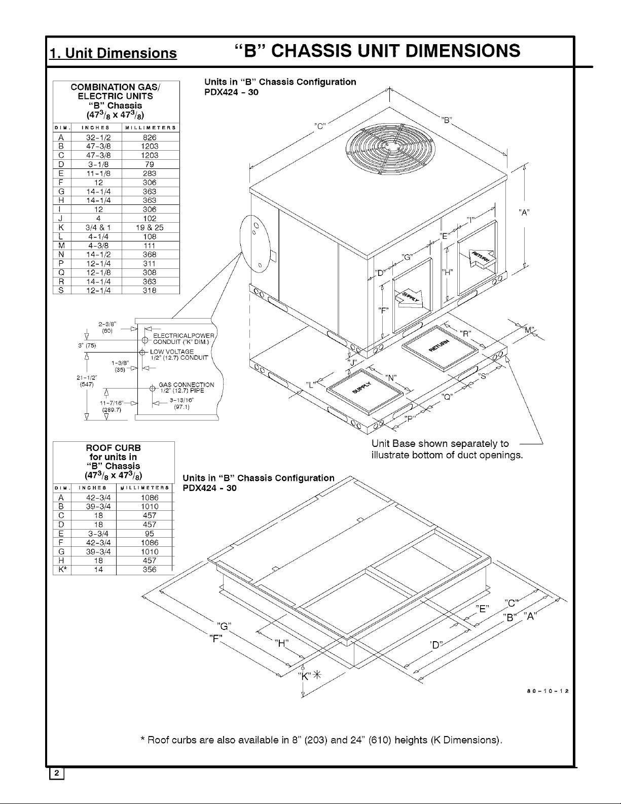
1. Unit Dimensions "B" CHASSIS UNIT DIMENSIONS
COMBINATION GAS/
ELECTRIC UNITS
"B" Chassis z A
DIM.
A
32-1/2 826 _ _ _ _,_,_-_"_._"_.
B
47-3/8I 1203 _ _ f(_d((_'_%_ _
C
47-3/8 I 1203 J J _ _N_.._.___._/ _. "_
D
3-1/8 I 79 _" _ _"___ _ ./i"
E
11-1/8 283 _ _
F
G
H
I
J
K
L
M
N
P
Q
R
S
12 I 308 _
14-1/4 I 363 L_ _
14-1/4 I 363 _ _
12 I 308 "_ _ _ 'w'
4 102 "1''j
3,4 I19 28
4-1/4I lO8 [ _ _ _ "E'_
4-3/8 111 .._ _ __ ....._-_ < .
14-1/2 I 368 _ ["1 _"""_/_ ...../ f "_
12-1/4 I 311 y/ _, _ )-d .... ,._ |,L--4 _ ,_
12-1/8 308 j / _ "D" _ "H" _"-_/
14-1/4 363 / / *" _ _"
12-1/4 I 318 _" / _. I _>_. _
Units in "B" Chassis Configuration
PDX424 - 30
I "F"
f 1-3/8" _ _NDUIT k _ _ _ S_'_-_
A ,. I '2"3'1123]16,PIP E
ROOF CURB Unit Base shown separately to
for units in illustrate bottom of duct openings,
"B" Chassis
(473/8 x 473/8) Units in "B" Chassis Configuration_
DIM.
,NC,E_ M......... 8 PDX424 - 30 _ _.
A
42-3/4 1086 .,._v
B
39-3/4 1010 J_ _
C
D
E
F
G
H
K*
18 457 _ _ _
18 457 _ j
3-3/4 98 _ _ _.....-_
42-3/4 1086 _ J _ _._
39-3/4 1010 _ _ J_ _ _.
18 457 __ _<'_ _- _- _ /'-_l
_ ..... __ _ _._ _,,B:_ A
* Roof curbs are also available in 8" (203) and 24" (610) heights (K Dimensions).
Page 3

2-3/8"
3i (75) 1-3/8"
25-1/16"
COMBINATION GAS/
ELECTRIC UNITS
"C" Chassis
(473/8 x 73)
DIN INCHE8 _41LLOMEYER8
A 36 914
B 47-3/8 1203
C 73 1354
D 4-5/8 117
E 15 361
F 12 307
G 18-3/4 476
H 18-3/4 476
I 12 306
J 4 102
K 1 &1-1/4 25&31
L 4-1/4 108
M 5-1/4 133
N 12-1/4 311
P 19 483
Q 15 381
R 19 483
S 12-1/4 318
T 16-7/8 429
ROOF CURB
for
"C" Chassis
(473/8 x 73)
IM INCHES MgLLIM_T_RS
A 67-3/4 1721
B 64-3/4 1645
C 23 584
D 23 584
E 2-1/2 64
F 42-3/4 1086
G 39-3/4 1010
H 23 584
I 12 305
J 12 305
K* 14 356
"C" CHASSIS UNIT DIMENSIONS
ECTRICAL POWER
CONDUIT ('l(" DIM.)
W VOLTAGE
1/2" (12.7) CONDUIT
GAS CONNECTION
1/2" (12.7) PIPE
(97.1)
3-13/16"
,,p,,
Unit Base shown separately to
illustrate bottom of duct openings,
Units in "C" Chassis Configuration
PDX436-42
"F'L
* Roof curbs are also available in 8" (203) and 24" (610) heights (K Dimensions),
13
Page 4
3" (75)
l 1-3/8"
31-1/16"
(789 4)
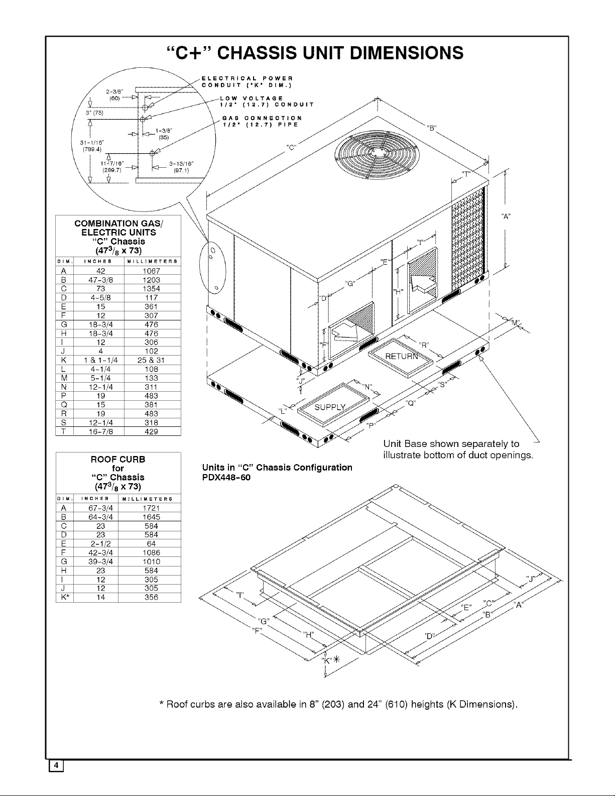
"C+" CHASSIS UNIT DIMENSIONS
ECTRICAL POWER
CONDUIT ('K" DIM.)
W VOLTAGE
_/2" (12.7) CONDUIT
GAS CONNECTION
1/2" (12.7) PIPE
"C"
1 (2_79,7) 3-13/16"
COMBINATION GAS/
ELECTRIC UNITS
"C" Chassis
(473/8 x 73)
DIM
INOHE8 MILL_MEYER8
A
B
C
D
E
F
G
H
I
J
K
L
M
N
P
Q
R
S
T
42 1067
47-3/8 1203
73 1354
4-5/8 117
15 361
12 307
18-3/4 476
18-3/4 476
12 306
4 102
1 &1-1/4 25&31
4-1/4 108
5-1/4 133
12-1/4 311
19 483
15 381
19 483
12-1/4 318
16-7/8 429
ROOF CURB
for
"C" Chassis
(473/8 x 73)
IM INCHES MOLLIM_T_RS
A 67-3/4 1721
B 64-3/4 1645
C 23 584
D 23 584
E 2-1/2 64
F 42-3/4 1086
G 39-3/4 1010
H 23 584
I 12 305
J 12 305
K* 14 356
(97.1)
,,p,,
Unit Base shown separately to
illustrate bottom of duct openings,
Units in "C" Chassis Configuration
PDX448-60
141
"F'L
* Roof curbs are also available in 8" (203) and 24" (610) heights (K Dimensions),
Page 5
2. SAFE INSTALLATION REQUIREMENTS
Installation and servicing of air-conditioning equipment can
be hazardous due to system pressure and electrical
components. Only trained and qualified personnel should
install, repair, or service air-conditioning equipment.
Untrained personnel can perform basic maintenance
functions of cleaning coils and filters. All other operations
should be performed by trained service personnel. When
working on air-conditioning equipment, observe
precautions inthe literature, tags, and labels attached to the
unit, and other safety precautions that may apply.
Follow all safety codes. Wear safety glasses and work
gloves. Use quenching cloth for unbrazing operations.
Have fire extinguisher available for all brazing operations.
FIRE, EXPLOSION, ELECTRICAL SHOCK, AND
CARBON MONOXIDE POISON HAZARD
Improper installation, adjustment, alteration, service,
maintenance, or use can cause carbon monoxide
poisoning, fire, or an explosion which could result in
personal injury or unit damage. Consult a qualified
installer, service agency, or gas supplier for information
or assistance. The qualified installer or agency must use
only factory-authorized kits or accessories when
modifying this product.
FIRE, EXPLOSION, ELECTRICAL SHOCK, AND
CARBON MONOXIDE POISON HAZARD
Failure to follow this warning could result in personal
injury, death and/or property damage.
Before performing service or maintenance operations
on unit, turn off gas supply to unit. Then turn off unit main
power switch and install lockout tag.
Recogniz_ safety information. This is the safety-alert
symbol/.rk. When you see this symbol in instructions or
manuals, be alert to the potential for personal injury.
Understand the signal words DANGER, WARNING,
CAUTION, and NOTE. These words are used with the
safety-alert symbol. DANGER identifies the most serious
hazards which will result in serious injury or death.
WARNING signifies a hazard which could result in serious
injury or death. CAUTION is used to identify unsafe
practices which may result in minor personal injury or
product and property damage. NOTE is used to highlight
suggestions which will result in enhanced installation,
reliability, or operation.
These instructions cover minimum requirements and
conform to existing national standards and safety codes. In
some instances, these instructions exceed certain local
codes and ordinances, especially those that may not have
kept up with changing residential construction practices.
We require these instructions as a minimum for a safe
installation.
FIRE, EXPLOSION, ELECTRICAL SHOCK, AND CARBON
MONOXIDE POISON HAZARD
Failure to carefully readand follow all instructions in this
manual could result in furnace malfunction, property
damage, personal injury and/or death.
Installation or repairs made by unqualified persons can
result in hazards to you and others. Installation MUST
conform with local building codes or, in the absence of
local codes, with the National Fuel Gas Code NFPA
54-2005/ANSI Z223.1-2005 and the National Electrical
Code NFPA70-2005 or in Canada the National Standard
CAN/CGA B149-1 and CSA C.22.1 - Canadian Electrical
Code Part 1.
The information contained in this manual is intended for
use by a qualified service technician familiar with safety
orocedures and equipped with the proper tools and test
instruments.
SAFETY CONSIDERATIONS
• Use only with type of gas approved for this unit. Refer to
unit rating plate.
• Install this unit only in a location and position as specified
in section 3 of this manual.
• Never test for gas leaks with an open flame. Use a com-
mercially available soap solution made specifically for the
detection of leaks to check all connections, as specified in
section 5.
•Always install unit to operate within the unit's intended
temperature-rise range with a duct system, which has an
external static pressure within the allowable range, as
specified in section 9. Refer to unit rating plate for the al-
lowable external static pressures.
•All connecting ductwork to the unit (supply and return)
must be sealed to the unit casing as specified in section 7.
• Do NOT use this furnace as a construction heater.
•Check to see that filters are installed correctly and are the
proper type an size.
NOTE: Itis the personal responsibility and obligation of the
customer to contact a qualified installer to ensure that the
installation is adequate and conforms to governing codes
and ordinances.
UNIT SAFETY
Failureto follow this caution may reduceunit reliability.
It is recommended that a qualified service technician
check the heat exchanger integrity everytwo (2)years,
after the first four (4) years of operation.
INTRODUCTION
The PDX4 unit is a fully self-contained, combination
Category Igas heating/electric heat pump unit designed for
outdoor installation (See pages 2 to 4 for unit dimensions).
All unit sizes have return and discharge openings for both
horizontal and downflow configurations, and are
factory-shipped with all downflow duct openings covered.
Page 6
Unitsmaybeinstalledeitherona rooftop,cementslab,or
directlyonthegroundiflocalcodespermit.
Modelswitha'l" inthetwelfthpositionofthemodelnumber
are dedicatedLowNOxunitsdesignedfor California
installations.Theemissionsofthesemodelsdonotexceed
40nanogramsofnitrogenoxideemissionsperjouleofheat
outputasshippedfromthefactory,andmustbeinstalledin
CaliforniaAirQualityManagementDistrictsor anyother
regionsinNorthAmericawherea LowNOxruleexists.
3. LOCATING THE UNIT
ACCESS PANELS
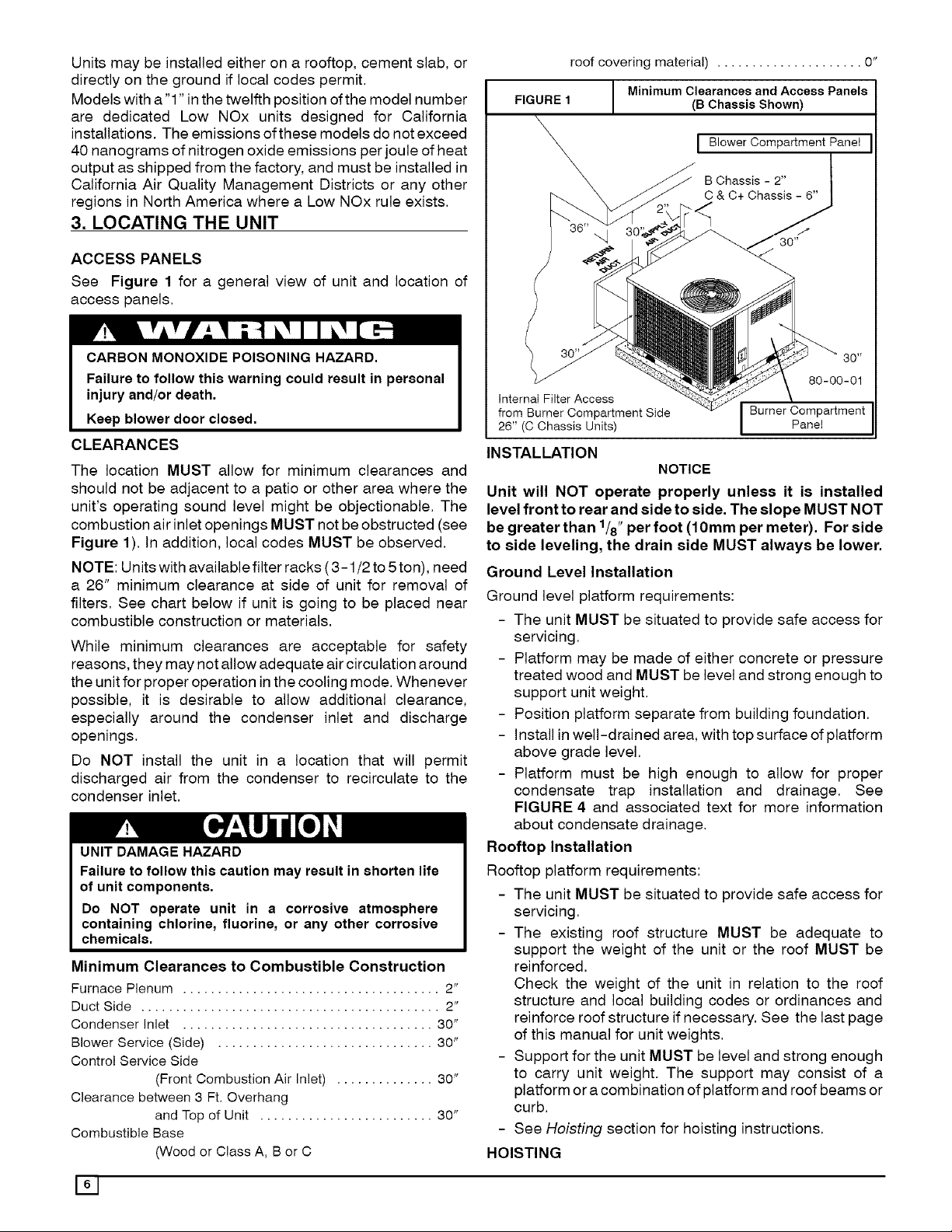
See Figure 1 for a general view of unit and location of
access panels.
CARBON MONOXIDE POISONING HAZARD.
Failure to follow this warning could result in personal
injury and/or death.
Keep blower door closed.
CLEARANCES
The location MUST allow for minimum clearances and
should not be adjacent to a patio or other area where the
unit's operating sound level might be objectionable. The
combustion air inlet openings MUST not be obstructed (see
Figure 1). In addition, local codes MUST be observed.
NOTE: Units with available filter racks (3-1/2 to 5ton), need
a 26" minimum clearance at side of unit for removal of
filters. See chart below if unit is going to be placed near
combustible construction or materials.
While minimum clearances are acceptable for safety
reasons, they may not allow adequate air circulation around
the unit for proper operation inthe cooling mode. Whenever
possible, it is desirable to allow additional clearance,
especially around the condenser inlet and discharge
openings.
Do NOT install the unit in a location that will permit
discharged air from the condenser to recirculate to the
condenser inlet.
UNIT DAMAGE HAZARD
Failure to follow this caution may result in shorten life
of unit components.
Do NOT operate unit in a corrosive atmosphere
containing chlorine, fluorine, or any other corrosive
chemicals.
Minimum Clearances to Combustible Construction
Furnace Plenum ..................................... 2"
Duct Side ........................................... 2"
Condenser Inlet .................................... 30"
Blower Service (Side) ............................... 30"
Control Service Side
(Front Combustion Air Inlet) .............. 30"
Clearance between 3 Ft. Overhang
and Top of Unit ......................... 30"
Combustible Base
(Wood or Class A, B or C
roof covering material) ..................... 0"
FIGURE 1
I Minimum Clearances and Access Panels
B Chassis Shown)
\
80-00-01
Internat Filter Access
from Burner Compartment Side
26" (C Chassis Units)
INSTALLATION
NOTICE
Unit will NOT operate properly unless it is installed
level front to rear and side to side. The slope MUST NOT
be greater than 1/8"per foot (10mm per meter). For side
to side leveling, the drain side MUST always be lower.
Ground Level Installation
Ground level platform requirements:
- The unit MUST be situated to provide safe access for
servicing.
- Platform may be made of either concrete or pressure
treated wood and MUST be level and strong enough to
support unit weight.
- Position platform separate from building foundation.
- Install in well-drained area, with top surface of platform
above grade level.
- Platform must be high enough to allow for proper
condensate trap installation and drainage. See
FIGURE 4 and associated text for more information
about condensate drainage.
Rooftop Installation
Rooftop platform requirements:
- The unit MUST be situated to provide safe access for
servicing.
- The existing roof structure MUST be adequate to
support the weight of the unit or the roof MUST be
reinforced.
Check the weight of the unit in relation to the roof
structure and local building codes or ordinances and
reinforce roof structure if necessary. See the last page
of this manual for unit weights.
- Support for the unit MUST be level and strong enough
to carry unit weight. The support may consist of a
platform or acombination of platform and roof beams or
curb.
- See Hoisting section for hoisting instructions.
HOISTING
Burner Compartment
Panel
161
Page 7
NOTE: All access panels MUST be secured inplace before
hoisting.
The unit should be hoisted with two lifting slings. Attach the
slings to rigging shackles that have been hooked through
holes in the base rail,
Two spreader bars MUST be placed on top of the unit to
protect the unit from damage from the pressure exerted by
the slings. Make sure that all equipment is adequate to
handle the weight ofthe unit and that the slings will not allow
the unit to shift,
Refer to Figure 20 on the back cover of this manual for
illustrated rigging instructions and weight chart,
DOWNFLOW CONVERSION
NOTE: In downflow applications with roof curbs or jack
stands, the center rail under the unit must be removed. The
center rail is attached to the base rail with screws.
These units are adaptable to downflow use, To convert to
downflow use, follow these steps:
1, Remove the blockoff plates found in the return air
compartment and the supply air compartment.
NOTE: Blockoff plate in the supply air compartment only
contains one screw. If reinstalling plate, back part of plate
MUST fit into mating dimples on flange. To reinstall, slant
plate into dimples, then put plate into position and fasten
with screw,
I FIGURE 2 I Heating vent Assembly I
Screwsfor
"B" Chassis
(473/8 x 473/8)
/
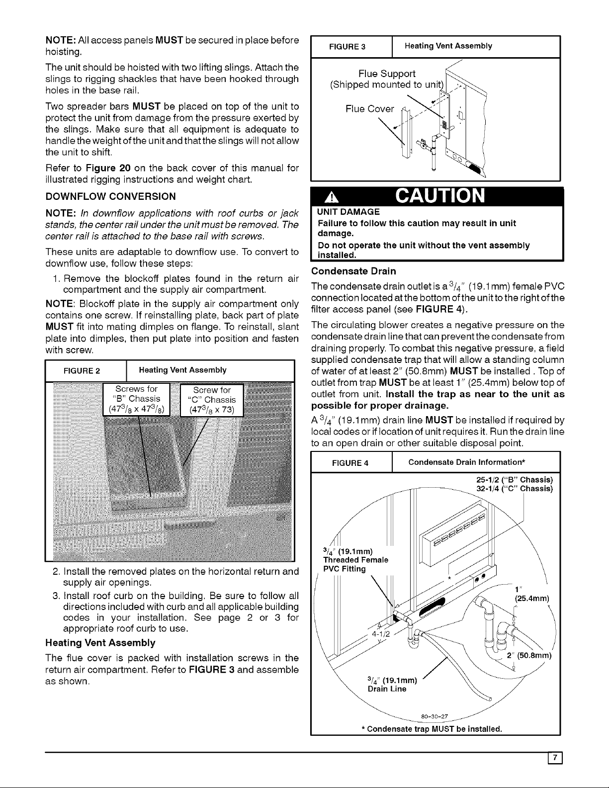
FIGURE 3 1 Heating Vent Assembly
Flue Support
(Shipped mounted to unit
Flue Cover
Condensate Drain
The condensate drain outlet is a 3/4" (19.1mm) female PVC
connection located atthe bottom of the unit tothe right of the
filter access panel (see FIGURE 4).
The circulating blower creates a negative pressure on the
condensate drain line that can prevent the condensate from
draining properly. To combat this negative pressure, afield
supplied condensate trap that will allow a standing column
of water of at least 2" (50.8mm) MUST be installed. Top of
outlet from trap MUST be at least 1" (25.4mm) below top of
outlet from unit. Install the trap as near to the unit as
possible for proper drainage,
A 3/4" (19.1 mm) drain line MUST be installed if required by
local codes or if location of unit requires it. Run the drain line
to an open drain or other suitable disposal point,
2. Install the removed plates on the horizontal return and
supply air openings.
3, Install roof curb on the building. Be sure to follow all
directions included with curb and all applicable building
codes in your installation. See page 2 or 3 for
appropriate roof curb to use.
Heating Vent Assembly
The flue cover is packed with installation screws in the
return air compartment, Refer to FIGURE 3 and assemble
as shown,
FIGURE 4
3/4" (19.1mm)
Threaded Female
* Condensate trap MUST be installed.
/ Condensate Drain Information*
25-1/2 ("B" Chassis)
32-1/4 ("C" Chassis)
(25.4mm)
2" (50.8mm)
171
Page 8
4. PRE-EXISTING COMMON VENT CHECK
If the installation of this new combination gas heat/electric
cool unit involves removing an existing gas-fired furnace
from a common vent system with other gas-fired
appliances (gas-fired hot water heater, etc.), the existing
vent system must be checked and inspected by a qualified
technician. The qualified technician can determine if the
existing vent system will properly vent the flue products of
the remaining gas-fired appliances. In many cases, the
existing vent system may be oversized for the remaining
appliances.
5. GAS SUPPLY AND PIPING
NOTE: Because there are many types of liquified petroleum
(propane (LP)) gases, the term propane (LP) as used inthis
manual refers to propane gas. Ifyou intend to use any type
of propane (LP) gas, proper precautions MUST be used in
the handling, piping, and use of such gas. NOTE: In
Canada, installations MUST be performed by licensed
propane (LP) installers.
The UL rating plate located on the side panel on the unit
contains the model number, type of gas, gas input rating,
and other important information.
FIRE OR EXPLOSION HAZARD
Failure to follow this warning could result in personal
injury, death and/or property damage.
Makecertainthe unitisequippedtooperateonthetype of
gasavailable.Models designatedasnatural gas areto be
used with natural gas only. Models designated for use
with liquefied petroleum (propane (LP)) gas are shipped
with orifices sized for commercially pure propane gas.
They MUST not be used with butane or a mixture of
butane and propane unless properly sized orifices are
installed by a licensed propane (LP) installer.
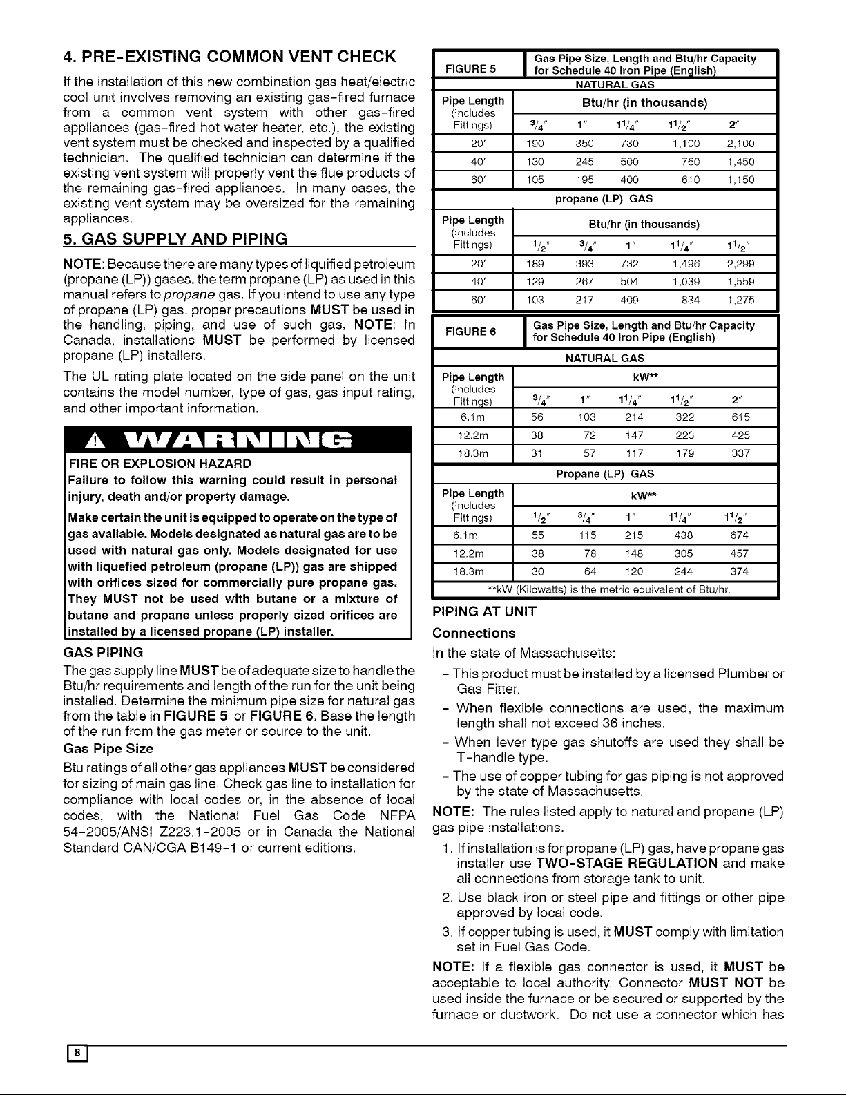
GAS PIPING
The gas supply line MUST be of adequate size to handle the
Btu!hr requirements and length of the run for the unit being
installed. Determine the minimum pipe size for natural gas
from the table in FIGURE 5 or FIGURE 6. Base the length
of the run from the gas meter or source to the unit.
Gas Pipe Size
Btu ratings of all other gas appliances MUST beconsidered
for sizing of main gas line. Check gas line to installation for
compliance with local codes or, in the absence of local
codes, with the National Fuel Gas Code NFPA
54-2005/ANSI Z223.1-2005 or in Canada the National
Standard CAN/CGA B149-1 or current editions.
FIGURE 5 for Schedule 40 Iron Pipe tEn_llish/
Pipe Length Btu/hr (in thousands)
(includes
Fittings) 3/4" 1 " 11/4" 11/2" 2"
20' 190 350 730 1,100 2,100
40' 130 245 500 760 1,450
60' 105 195 400 610 1,150
Pipe Length Btu/hr (in thousands)
(includes
Fittings) 1/2" 3/4" 1" 11/4" 11/2"
20' 189 393 732 1,496 2,299
40' 129 267 504 1,039 1,559
60' 103 217 409 834 1,275
FIGURE 6 for Schedule 40 Iron Pipe (English)
Pipe Length kW**
(includes
Fittinqs) 3/4" 1 " 11/4" 11/2" 2"
6.1m 56 103 214 322 615
12.2m 38 72 147 223 425
18.3m 31 57 117 179 337
Pipe Length kW**
(includes
Fittings) 1/2" 3/4" 1" 11/4" 11/2"
6.1m 55 115 215 438 674
12.2m 38 78 148 305 457
18.3m 30 64 120 244 374
I Gas Pipe Size, Length and Btu/hr Capacity
NATURAL GAS
propane (LP) GAS
I Gas Pipe Size, Length and Btu/hr Capacity
NATURAL GAS
Propane (LP) GAS
**kW (Kilowatts) is the metric equivalent of Btu/hr.
PIPING AT UNIT
Connections
In the state of Massachusetts:
- This product must be installed by a licensed Plumber or
Gas Fitter.
- When flexible connections are used, the maximum
length shall not exceed 36 inches.
- When lever type gas shutoffs are used they shall be
T-handle type.
- The use of copper tubing for gas piping is not approved
by the state of Massachusetts.
NOTE: The rules listed apply to natural and propane (LP)
gas pipe installations.
1. Ifinstallation is for propane (LP) gas, have propane gas
installer use TWO-STAGE REGULATION and make
all connections from storage tank to unit.
2. Use black iron or steel pipe and fittings or other pipe
approved by local code.
3. tf copper tubing is used, it MUST comply with limitation
set in Fuel Gas Code.
NOTE: If a flexible gas connector is used, it MUST be
acceptable to local authority. Connector MUST NOT be
used inside the furnace or be secured or supported by the
furnace or ductwork. Do not use a connector which has
181
Page 9

previously serviced another gas appliance. Always use a LEAK CHECK/PRESSURE TESTING OF GAS SUPPLY
new listed connector. PIPING
FIRE OR EXPLOSION HAZARD
Failure to do so could result in personal injury, death
and/or property damage.
Gas connector MUSTbeproperlyinstalledand can NOT
be usedinside thefurnace.
4. Use pipe joint compound on external (male) threads
ONLY. Joint compound MUST be resistant to any
chemical action of propane (LP) gases. Do NOT put
pipe compound on last 2 threads of pipe.
5. Use ground joint unions and install a drip leg no less
than 3 inches (76 mm) long to trap dirt and moisture
before it can enter gas valve.
UNIT OPERATION AND COMPONENT DAMAGE HAZARD
Failure to follow this caution may result in misaligned
burners, flame rollout and or unit damage.
Overtightening assembly may cause damage to the gas
valve and/or wirin_land may misali_lnthe burners.
6. Use a wrench on gas valve when making connections
to prevent gas valve from turning. Do NOT use a pipe
wrench on the gas valve body.
7. Provide a t/8 inch (3mm) National Pipe Thread (NPT)
plug for test gauge connection immediately upstream of
the gas supply connection to the furnace if none is
supplied with the gas valve of unit.
8. Install a manual shutoff valve and tighten all joints
securely.
FIRE OR EXPLOSION HAZARD
Failure to follow the safety warnings could result in per-
sonal injury, death or property damage.
Never test for gas leaks with an open flame. Use a com-
mercially available soap solution made specifically for
the detection of leaks to check all connections. A fire or
explosion may result causing property damage, person-
al injury or loss of life.
The unit and its equipment shutoff valve must be
disconnected from the gas supply piping system during any
pressure testing of that system at test pressures in excess
of .5 psi (3.5kPa).
The unit must be isolated from the gas supply piping system
by closing the equipment shut off valve during any pressure
testing of the gas supply piping system at test pressures
equal to or less than .5 psi (3.5 kPa).
ORIFICES
Orifice Sizes
Orifice sizes MUST be matched to the heating value of the
gas (see TABLE 1 & 2). Check with your gas supplier and
the National Fuel Gas Code ANSI Z223.1.
NOTE: A Propane (LP) Conversion Kit MUST be used for
conversion to propane (LP) gas.
NOTE: For elevations above 2000 feet (610 meters), the
Btu input rating MUST be reduced by 4% for each 1000 feet
(305 meters) above sea level, unless the gas supplier's
Btu/ft3 content has already been adjusted for altitude.
Check Table 1 & 2 for the proper orifice sizes.
191
Page 10

Table I NATURAL GAS MANIFOLD PRESSURE ("w c )
0 to 2001 to 300I to 4001 to 500I to 6001 to 700I to 6001 to 9001 to
HEATING 2000 3000 4000 5000 6000 7000 8000 9000 10000
VALUE at
ALTITUDE Odfic_ MnfldPress Orlfic_ MnfldPress Odfic_ MnfldPress Odfic_ MnfldPress Oriflc_ MnfldPress Orifice MnfldPress 9dflc_ MnfldPress Dr4fice MnfidPress 3dfice MnfldPress
BTU/CU. FT No Hi Lo No Hi Lo No Hi Lo No Hi Lo No Hi Lo No Hi Lo No. Hi Lo No Hi Lo No. Hi Lo
700 47 37 18 48 36 1.8 49 36 18
725 46 36 1.7 47 35 17 48 34 1.7 49 34 17
750 46 33 1.6 46 37 18 49 37 1.8 50 37 18
775 46 36 1 6 47 35 1.7 48 35 17 49 35 1.7 50 35 17
600 45 37 1.8 46 34 17 47 33 1.6 46 33 16 49 33 1.6 50 33 16
625 46 37 1.8 47 36 16 48 36 1.7 49 36 18 50 36 1.8 51 37 18
850 45 37 18 46 34 1.7 47 34 17 48 34 1.6 49 34 17 50 34 1.7 51 35 17
675 46 37 18 47 37 1.8 46 37 16 49 37 1.8 49 32 16 50 32 1.6 51 33 16
900 46 35 17 47 35 1.7 46 35 17 4g 35 1.7 50 36 18 5I 37 1.8 51 3I 15
925 43 3.4 17 45 36 18 46 33 16 48 37 1.8 46 33 16 49 33 1.6 50 34 17 5I 35 1.7 52 36 18
950 44 3.7 18 46 36 18 47 36 17 48 36 1.7 49 36 18 50 37 1.6 50 32 16 5I 33 1.6 52 34 17
975 44 3.5 17 46 34 17 47 34 17 48 34 1.7 49 35 17 50 35 1.7 51 36 18 5I 31 1.5 52 33 16
1000 44 3.3 16 47 37 I8 46 37 18 48 32 1.6 49 33 16 50 34 1.6 51 34 17 52 37 1.8 52 3I 15
1050 45 3.6 18 47 33 I6 46 3.3 16 49 34 I7 50 35 17
II00 46 3.5 17 48 34 I7 49 3.6 17 50 37 I8
Note: The orifice sizes inthe chad above derate the input rate at 4% per 1000 feet above sea level for altitudes exceeding 2000 feet above sea level
If converting from propane (LP) gas to Natural Gas, use kit number 1175405 for altitudes up to 2000 feet above sea level
If converting from propane (LP) gas to Natural Gas, use kit number 1175405 and altitudes exceeding 2000 feet above sea level, use kit number 1I 75405 with field-supplied orifices
Natural gas data Jsbased on .6 specific gravity
For fuels with different specific gravity, consuk the National Fuel Gas Code NFPA 54-2605/ANSI Z223.1 - 2005 or
National Standard of Canada, Natural Gas and Propane Installation Code CSA B149.1-05
Table 2
HI-AIIN(5
VALUE at
ALTITUDE Oto 2000 2001to3000 3001to4000 7001to8000 8001to9000 9001to10000
MEAN ELEVATION FEET ABOVE SEA LEVEL
PROPANE (LP) GAS MANIFOLD PRESSURE ("w.c.)
MEAN ELEVATION FEET ABOVE SEA LEVEL
4001to5000 5001to6000 600tto7000
2500 10.0 5.5 10.0 5.0 11.0 6.0 11.0 5.7 10.7 5.2 10.0 5.0 11.0 5.9 10.6 5.2 10.0 5.0
Orifice Size # 55 # 55 # 56 #56 #56 # 56 # 57 #57 #57
KitNumber 1175406
Note:The orificesizes in thechart above deratethe inputrate at 4% per 1000feet abovesea level foraltitudesexceeding 2000feet abovesea level.
Propane(LP) gasdatais basedon f.52 specificgravity.
For fuelswith differentspecificgravity, consultthe NationalFuel GasCodeNFPA54-2005/ANSIZ223.1- 2005 or
NationalStandardof Canada,Natural Gas andPropane InstallationCodeCSA B149.f-05.
Changing Orifices
3. Disconnect the wires from the gas valve, sparker, and
flame sensor.
4. Remove the four screws holding the manifold to the
manifold brackets.
ELECTRICAL SHOCK, FIRE AND/OR EXPLOSION
HAZARD
Failure to follow this warning could result in personal
injury, death and/or property damage.
5. Carefully remove the manifold with the gas valve
attached.
6. If unit has v-shaped NOx baffles installed in the firing
tubes, they must be removed when coverting to
propane (LP). Some baffles may be attached by
Shut off electric power at unit disconnect or service
panel and shut off gas at manual shut off valve before
beginning the following procedure.
Changing orifices requires a qualified service
technician.
1. Shut OFF gas at manual shut off valve.
2. Shut OFF electric power at unit disconnect or service
panel. If unit is still running, allow 3 minutes after gas
screws. Replace screws after removing NOx baffles
(figure 7).
CARBON MONOXIDE HAZARD.
Failure to follow this warning could result in per-
sonal injury death and/or property damage.
NOx baffles for use with Natural Gas units ONLY. If
propane (LP) Gas is required, NOx inserts must be
YAml_v_t'{
shut off before turning off power.
Page 11

FIGURE 7 i Removing NOx Baffles
or
25-22-46a
7. Remove the orifices from the manifold with a 7/t6" box
end or socket wrench.
8. Check to be sure that the size of each orifice is correct
for the Btu input desired.
6. ELECTRICAL WIRING
ELECTRICAL SHOCK HAZARD.
Failure to follow this warning could result in personal
injury, death, and/or property damage.
The unit cabinet must have an uninterrupted,
unbroken electrical ground to minimize the possibility
of serious injury if an electrical fault should occur.
This ground may consist of an electrical wire
connected to the unit ground lug in the control
compartment, or conduit approved for electrical
ground when installed in accordance with National
Electric Code (NEC) NFPA 70, National Fuel Gas Code
NFPA 54-2005/ANSI Z223.1-2005 and local electrical
codes. In Canada, follow Canadian Electrical Code
CSA (Canadian Standards Association) C22.1 and
local electrical codes.
REDUCED EQUIPMENT LIFE HAZARD
FIGURE 8 Manifold/Orifice Measurement
_lpi°l_e°rifiee
9. Install the correct orifices. Gauge the size ofthe orifices
with a new twist drill bit of the correct size.
Make sure that the orifices go in straight so that they
form a right angle (90 °) to the manifold pipe.
Tighten the orifices so that there is a 13/16" distance
between the faces of the orifices to the back of the
manifold pipe.
Measure the distance with a set of calipers. Ifyou do not
have a calipers, you can use an adjustable wrench and
measure between the face of the jaws.
1O.Reassemble in reverse order.
Failure to follow these cautions could result in damage
to the unit being installed.
1) Make all electrical connections in accordance with
National Electric code (NEC) NFPa 70, National Fuel Gas
Code NFPA 54-2005/ANSI Z223.1-2005 and local
electrical codes governing such wiring. In Canada, all
electrical connections must be in accordance with CSA
standard C22.1, Canadian Electrical Code Part 1, and
applicable local codes. Refer to unit wiring diagram.
2) Use only copper conductor for connections between
field-supplied electrical disconnect switch and unit. DO
NOT USE ALUMINUM WIRE.
3) Be sure that high-voltage power to unit is within
operating voltage range indicated on unit rating plate.
4) Do not damage internal components when drilling
through any panel to mount electrical hardware,
conduit, etc. Consult local power company for
correction of improper voltage and/or phase imbalance.
For access, remove the burner access panel. See Figure
for access panel location. Wiring MUST be protected from
possible mechanical damage.
Disconnect Switch
The unit must have separate electrical service with a
field-supplied, waterproof, disconnect switch mounted at,
orwithin sight from, the unit. Refer tothe unit rating plate for
maximum fuse/circuit breaker size and minimum circuit
amps (ampacity) for wire sizing.
Ground Connections
Do NOT complete line voltage connections until unit is
permanently grounded. All line voltage connections and the
ground connection MUST be made with copper wire.
A ground lug is installed in the control box area for the
ground connection. Use a copper conductor of the
appropriate size from the unit to a grounded connection in
the electrical service panel or a properly driven and
electrically grounded ground rod. See warning above.
Page 12

LineVoltageWiring
Connectionsforlinevoltagearemadeintheunitcontrolbox
area.RefertowiringdiagramlocatedontheBurnerAccess
panel.Foraccess,removetheburneraccesspanel.
1.Runthehighvoltage(L1,L2)andgroundleadsintothe
controlbox.
2.Connectgroundleadtochassisgroundconnection.
3.ConnectL1 to pressurelugconnection11 of the
compressorcontactor.
4.ConnectL2 to pressurelug connection23 of the
compressorcontactor.
Thermostat/ Low Voltage Wiring
Location of the thermostat has an important effect on home
comfort. FOLLOW THE THERMOSTAT INSTRUCTION
MANUAL FOR CORRECT LOCATION, MOUNTING, AND
WIRING.
A two-stage thermostat is required for proper operation.
Thermostat must have the following terminals: "R",
"W/W1 ", "Y1", "Y2", and "G'. Some electronic thermostats
use low voltage from the unit for power for temperature
display and programming. These electronic thermostats
will have a "C" terminal. The outdoor unit has color-coded
wires for easy connection. Using wire nuts, follow figure 9
for proper connections:
PLEASE NOTE: While a high stage heat pigtail is provided
('W2", BLK), the approved thermostat will not respond to
this connection. Make sure that dip switch 3 on the ignition
control board is in the "OFF" position. The ignition control
board is inthe control box assembly, and the wiring diagram
label will show the correct dip switch position. With dip
switch 3 inthe "OFF" position, gas heating will always be on
low stage for the first 10 minutes. If after 10 minutes of
continuous low stage gas heat operation the thermostat is
still not satisfied, the ignition control will step up to high
stage gas heat for the remainder of the thermostat call.
FIGURE 9 I Thermostat Connections
I
is the presence of 24V to the violet-colored pigtail.
Approved thermostats that have the "DH" terminal are
available through your distributor
THERMOSTAT HEAT ANTICIPATOR
Some thermostats have an adjustable heat anticipator. The
heat anticipator prevents temperature overshoot in heating
mode. If the heat doesn't turn off until the set point
temperature on the thermostat is exceeded, then the
anticipator setting is too low. If the heat turns off before the
thermostat reaches the set point temperature on the
thermostat, then the anticipator setting is too high. Follow
the thermostat instruction manual for proper adjustment of
the heat anticipator.
Final Electrical Check
1. Make afinal wiring check to be sure system is correctly
wired. Inspect field installed wiring and the routing to
ensure that rubbing or chafing due to vibration will not
occur.
NOTE: Wiring MUST be installed so it is protected from
possible mechanical damage.
BALANCE POINT TEMPERATURES
The dual fuel models require a dual fuel thermostat for
proper operation. A dual fuel thermostat allows a balance
point temperature to be programmed into the thermostat
and has an outdoor temperature sensor that must be
installed outside. Follow the thermostat installation
instructions for proper location of outdoor sensor. The dual
fuel unit operates either in heat pump mode or gas heat
mode, but NEVER both modes at the same time.
There are 2 different balance point temperatures to
consider when programming the thermostat: Economic
and Load.
Economic Balance Point Temperature
The economic balance point temperature is the outdoor
temperature where the utility cost of running in heat pump
mode is the same as running in gas heat mode. If the
outdoor temperature is above the economic balance point
temperature, then the heat pump mode will be less costly. If
the outdoor temperature is below the economic balance
point temperature, then the gas heat mode will be less
costly. The economic balance point temperature is affected
by electrical utility cost, gas utility cost, and model size.
Knowing the utility cost of electricity and gas, the economic
balance point temperature can be determined using Figure
10.
Thermostat and subbase
The violet-colored pigtail connects to the dehumidification
feature of this unit. The dehumidification feature reduces
cooling airflow by 20% to increase latent heat removal when
the humidity is high. The reduced airflow occurs when there
Unit ControJ Power
Figure 10 - Economic Balance Point Temperature Chart
Economic Balance Point Temperature (°F)
Cost PDX424 PDX430 PDX436 PDX442 PDX448 PDX460
Ratio* 040 060 080 080 100 100
0.075 0 0 2 0 1 2
0.100 20 19 20 20 18 18
0.125 42 32 34 34 31 29
0.1375 50 40 38 38 40 38
0.150 57 48 43 42 46 44
* CostRatioisthe electricalcost,in$ perkilowatt-hour,dividedbythegas
cost,in$ per therm.
Page 13

Example: A PDX442080 is installed in a residence where
the electrical utility cost is 9 cents per kilowatt-hour and the
gas cost is 90 cents per therm. Proceed as follows:
1. $.09/$.90 = .1
2. Using Figure 10, a PDX342080 with a .1 cost ratio =>
Economic Balance Point Temperature = 20°F
Some utilities have asliding cost based onconsumption. In
this case, take the total bill and divide by the total
consumption to determine the average utility cost.
Some natural gas suppliers sell gas by every 100 cubic feet
(CCF) of gas. For an approximate gas cost per therm,
multiply CCF by 97. Example: A price of $.01 per CCF is
approximately equivalent to $.97 per therm.
Note: The 97 multiplier is based on a typical heating
value of 1030 Btu per cubic foot of natural gas. For a
more accurate cost, contact your gas supplier to obtain
the Btu content of natural gas in your area. Divide
100,000 by the actual Btu content per cubic foot to obtain
the correct multiplier.
If the economic balance point is chosen, keep in mind that
utility rates fluctuate substantially over time. Review
monthly utility bills and re-calculate economic balance
)oints as necessary.
11 I Load Balance Point
Figure Temperature
m
I
Load Balance Point Temperature
The load balance point temperature is the outdoor
temperature at which the load may be met using either heat
pump mode or gas heat mode. Ifthe outdoor temperature is
above the load balance point temperature, the demand for
heat may be met using the heat pump mode. If the outdoor
temperature is below the load balance point temperature,
the gas heat mode is required to meet the building load.
To find the load balance point temperature, a load
calculation must be performed on the building. The load
calculation must be performed at 3 different outdoor
temperatures and graphed on Figure 11. Plot the three
load calculations at their appropriate outdoor temperatures
and draw a smooth line through the 3 points. NOTE: The
line connecting the 3 points may not be a straight line.
Locate where the building load line intersects the
appropriate model capacity line. This is the load balance
point temperature.
No matter what the balance point temperature is set at, the
unit will automatically switch to gas heat if the heat pump is
not able to meet the demand of the house. Calculating the
load balance point temperature and programming itinto the
thermostat will minimize temperature fluctuations in the
house.
Load Balance Point Temperature
10 20 30 40 50 60
Outdoor Air Temperature (F)
7. DUCTWORK
Ductwork Sizing
The maximum recommended velocity in trunk ducts is 1000
feet per minute. The maximum recommended velocity in
branch ducts is 800 feet per minute.
Ductwork sizing affects the discharge temperature, airflow
velocity, and efficiency of the system. Be sure to properly
size ductwork to the capacity of the unit and to the airflow
requirements of the conditioned space. Failure to properly
size ductwork can result in inadequate airflow and poor
efficiency. Undersized ductwork may result in tripped limit
controls and premature failure of compressors, motors and
other components.
Ductwork Insulation
Ductwork installed outdoors must have a minimum 2" thick
fiberglass "wrap" insulation and a weatherproof vapor
barrier installed around it. The insulation and vapor barrier
must be protected against potential damage. Caulking,
flashing, and other means of providing a permanent
weather seal must be used.
Ductwork Connections
The use of flexible, non-combustible connectors between
main trunk ducts and supply and return air plenums is
permitted. If flexible connectors are used, they should be
protected from potential mechanical damage such as
punctures and tears.
NOTE: When connecting the supply and return plenums to
the unit, make sure that the plenums are sealed against the
Page 14

sidecasingoftheunitanddonotinterferewithremovalof
thetopoftheunit.
FILTERS
AllreturnairMUSTpassthroughafilterbeforeenteringthe
unit.Anelectronicaircleaner,optionalfilterracks,orother
accessiblefilterarrangementmustbeinstalledinthereturn
airductwork.Minimumrecommendedfiltersizesarelisted
REDUCED EQUIPMENT LIFE HAZARD
Failure to follow this caution may result in improper
unit operation,
Do not operate the unit without a filter.
inFIGURE12andarebasedonmaximumfacevelocitiesof
300ft/minfordisposablefiltersand600ft/minforwashable
(highvelocity)filters.Seefigure10forfiltersizes.
Figure 12 Filter Sizes
Disposable Filters
Model
PDX424040
PDX430060
PDX436080
PDX442080
PDX448100
PDX460100
1 Washable filter size is based on an allowable face velocity of 600 ft/min. Refer to
filter manufacturer's specifications for allowable face velocity and required filter area.
Nominal Size Area(sq.
(qty x w x d) inches)
1 x 20" x 20" 384
1 x 20" x 24" 480
2 x 15" x 20" 576
2 x 18" x 20" 672
2 x 20" x 20" 768
2 x 20" x 24" 960
Minimum
Washable Filters'
NomlnaI Size
(w x d)
(inches)
1 x 10" x 20"
1 x 12" x 20"
1 x 15" x 20"
1 x 18" x 20"
1x20"x20"
1x20"x24"
Minimum
Area (sq.
inches)
192
240
288
336
384
48O
D2J
Page 15

8. AIRFLOW ADJUSTMENT
Figure 13
Model Tons
PDX424040 2
PDX430050 25
PDX436080 3
PDX442080 35
PDX448100 4
PDX460100 5
NOTES:
* Factory-shipped speed
NA = Not Allowed for Heating Speed
Cooling
Airflow Adjustment
COOLING
HighStage
High Stage Heating
CFM Heating Rise (°F)
Low Stage
Ext. Static Pressure (in we)
.1" ~ .7"
904 33
791 37
578 44
554 52
904 49
791 56
589 54
554 NA
1288 48
1164 53
1034 59
904 NA
1379 45
1288 48
1198 51
1113 55
1785 43
1719 45
1653 46
1588 48
1797 43
1732 44
1669 46
1605 48
Heating Rise
Range(°F)
25-55
25-55
25-55
25-55
25-55
25-55
HEAT PUMP - Comfort Mode
Low Stage Heating
Ext. Static Pressure (in wc)
.1" ~ .7"
Heating Rise (°F)
25
30
35
42
39
44
51
NA
38
42
47
NA
35
38
41
44
34
35
36
38
34
35
36
38
Model
PDX424040
PDX430060
PDX436080
PDX442080
PDX448100
PDX460100
Normal Dehumidy
Mode(CFM Mode(CFM)
800 640
875 700
1200 960
1400 1120
1600 1280
1750 1400
Dehumidify
Mode (CFM)
448
518
682
784
883
1036
HighStage LowStage
700 490
875 650
1050 746
1225 853
1450 998
1575 1170
L!2J
Page 16

CIRCULATING AIR BLOWER SPEEDS
ELECTRICAL SHOCK HAZARD.
Failure to follow this warning could result in personal
injury, death and/or property damage.
Turn off electric power supply at disconnect switch or
service panel before removing access or service panels
from unit.
GAS HEATING
Available heating speeds are listed in Figure 13. The
heating speeds may be selected by adjusting dipswitches 3
and 4 on the motor interface board. The motor interface
board may be found in the control box assembly. Refer to
wiring diagram on inside of the access panel for dip switch
settings. Please note that the setting of dipswitches 3 and 4
affects both the low stage gas heating speed and the high
stage gas heating speed.
COOLING
Cooling speeds are listed in Figure 13. In dehumidification
mode, cooling airflow is reduced to 80% of nominal.
CONTINUOUS FAN OPERATION
CHECK BEFORE STARTING
1. Check that the blower motor speed terminal block is
running the correct heating and cooling speeds.
2. Check to see that clean, properly sized air filters are
installed.
3, Replace all service access panels,
FIREOR EXPLOSIONHAZARD.
Failuretofollow this warning could resultin personalinjury
and/ordeath.
TurnOFFgasatshutoffbeforeconnectingU-tubemanometer.
Figure 14 J_ Honeywell Gas Valve
Regulator
Adjustment
/
©
For energy efficiency, continuous fan speed is 40% of the
high stage cooling speed,
COOLING
1. Turn electric power OFF
2. Set thermostat Heat-Cool select to COOL.
3. Adjust thermostat setting to below room temperature.
4. Turn power ON, for approximately one minute, then
OFF. During power application check the following:
a. Contactor - Contacts Closing
b. Compressor - ON
c. Condenser fan motor - ON
d. Circulating Air Blower - ON, Adustable delay ON of 0
or 30 seconds.
5. Turn power OFE check the following:
a. Contactor contacts opening.
b. Compressor - OFF
c. Condenser fan motor - OFF
d. Circulating blower - OFF, Adustable delay OFF of 0
or 90 seconds.
9. START-UP PROCEDURES
FIRE OR EXPLOSION HAZARD
Failure to follow this warning could result in personal
injury, death and/or property damage.
Do NOT attempt to light the burner with a match or
flame of any kind.
tntlet Pressure
Tap 1/8 NPT
Outlet Pressure
Tap 1/8 NPT
GASPRESSURES
1. Do NOT allow gas supply pressure to fall below the
listed minimums. Doing so will decrease input to
furnace. Refer to Figure 15 for gas supply pressures.
2. Gas input MUST NOT exceed rated input shown on
rating plate.
3. Do NOT allow pressures to exceed the maximum limits
as listed in Figure 15.
Figure 15 Gas Pressures
Natural Gas Propane (LP) Gas
Minimum 4.5 in wc (1120 Pa) 11 in wc (2740 Pa)
Inlet
Recommended 7 in wc (1740 Pa) 11 in wc (2740 Pa)
Inlet
Maximum 13 in wc. (3230 Pa) 13 in wc (3230 Pa)
Inlet
Manifold Pressure Adjustment
Manifold pressures are listed in Tables 1 and 2. Check
manifold pressures using the following procedure.
1. With gas OFF, connect U-Tube manometer to outlet
pressure tap on gas valve (see figure 14). Use a
manometer with a 0" to 12" water column range.
Page 17

2.Turn gas ON. Temporarilyset balancepoint
temperaturewarmenoughto lockout heatpump
operation.Changethermostatto HEATmodeand
adjusttemperaturesetpointtoatleast7degreesabove
roomtemperature.Makesurethatthethird(3rd)dip
switchontheignitionboardissetintheOFFposition
(Seewiringdiagram).Wait10minutesforunittoswitch
tohighstagegasheat.
3.Removethemanifoldpressureadjustmentscrewcover
ongasvalve.Turnhighstageadjustingscrew,marked
"HI", counterclockwiseto decreasethe manifold
pressureandclockwiseto increasepressure.See
figure14.
4.Setmanifoldpressureto valueshowninTable1 or
Table2. Replaceadjustmentscrewcover and
re-checkmanifoldpressure.
5.Turnthermostatmodeto OFF.Changethermostatto
HEATmodeand adjusttemperatureset point 5
degreesaboveroomtemperature.
NOTE:Fromthetimethethermostatissettogasheat,you
have10minutestocompletelowstagegasadjustments.
After10minutes,thethermostatwillshifttohighstagegas
heat.
6.Removethemanifoldpressureadjustmentscrewcover
ongasvalve.Turnlowstageadjustingscrew,marked
"LO', counterclockwiseto decreasethe manifold
pressureandclockwiseto increasepressure.See
figure14.
7.Setmanifoldpressureto valueshowninTable1or
Table2. Replaceadjustmentscrewcover and
re-checkmanifoldpressure.
8.Turn thermostat "OFF". Remove manometer
connectionfromtheoutletpressuretapofgasvalve
andreplacepluginoutletpressuretap.Seefigure14.
9.Returnthermostatto customer'sdesiredsettings
(balancepoint temperature,mode, and desired
temperature)afterfinalcheckout.
FIRE AND/OR EXPLOSION HAZARD
Failure to follow this warning could result in per-
sonal injury, death and/or property damage.
Do NOT adjust manifold pressure more than + 0.3
inches water column to obtain rated input.
GAS HEATING START-UP PROCEDURE
1. Temporarily set balance point warm enough to lock out
heat pump. Adjust thermostat setting above room
temperature and set thermostat selector to HEAT. The
combustion air blower will energize on high speed.
2. The combustion air blower will run on high speed for 15
seconds to purge the combustion chamber.
3. After the 15 second purge, the combustion air blower
will remain on. The sparker will turn on to ignite the gas
at the same time the gas valve is energized on low
stage. Make sure the gas valve is in the "ON" position
(Refer to Figure 14 and the instruction label located on
the inside of the burner access panel.
4. The sparker will remain energized for 7 seconds or until
a flame is detected by the flame sensor. It may take
several ignition attempts to purge the air out of the gas
line at the initial start-up of the unit.
5. Once flame is proven, the ignition control will switch the
combustion air blower to low speed. The unit will run in
low stage gas heat for 10 minute or until the thermostat
is satisfied, whichever is shorter. Ifthe thermostat is not
satisfied after 10 minutes, the unit will go to second
stage gas heat and run until the thermostat is satisfied.
6.30 seconds after the burners light, the circulating air
blower will begin to run.
7. After checking start up, return balance point
temperature to desired setting.
FIRE AND/OR EXPLOSION HAZARD
Failure to follow this warning could result in personal
injury, death, and/or property damage.
Do NOT attempt to light the burner with a match or
flame of any kind,
GAS HEATING INPUT RATE CHECK
The gas input tothe unit isdetermined by measuring the gas
flow at the meter. Measuring gas flow at the meter is
recommended for natural gas units. To measure the
heating input, perform the following steps for both low and
high stage:
1. Turn off all other gas appliances that use the same
meter.
Check the unit's operation as outlined in the following
instructions, tf any unusual sparking, odors or unusual
noises are encountered, shut off electric power
immediately. Recheck for wiring errors, or obstructions in or
near blower motors.
1. Set thermostat Heat-Cool selector to OFF.
2. Set thermostat fan switch to AUTO.
3. Turn electric power ON. Nothing should start running.
4. Turn manual gas valve ON.
5. Turn gas control valve ON.
6. Set thermostat fan switch to ON.
7. Reset thermostat fan switch to AUTO,
2. Turn off gas supply to unit and attach manifold
pressure manometer as instructed in the "Manifold
Pressure Adjustment" section. Turn gas ON.
3,
Temporarily set balance point temperature warm
enough to lock out heat pump operation. Change
thermostat to HEAT mode and adjust temperature set
point to at least 7 degrees above room temperature to
set unit to high stage. Wait 10 minutes for unit to
switch to high stage. Make sure that the third (3rd) dip
switch on the ignition board is set in the OFF position
(See wiring diagram).
4. Record the number of seconds for the gas meter dial
to make 1 revolution.
1171
Page 18

5, Divide number of seconds in step 4 into 3600 (number
of seconds in 1 hour).
6. Multiply result of step 5 by the number of cubic feet
shown for one revolution of the meter dial to obtain the
cubic feet of gas flow per hour.
7,
Multiply result of step 6 by Btu heating value of gas to
obtain total measured input in Btu/hr. Compare this
with the unit rating plate and make any adjustments
as needed according to the "Manifold Pressure
Adjustments" section. Consult with local gas supplier
if the heating value of gas is not known.
NOTE: From the time the thermostat is set to gas heat, you
have 10 minutes to complete low stage gas adjustments.
After 10 minutes, the thermostat will shift to high stage gas
heat.
8. Turn thermostat mode to OFF. Reset the thermostat
by changing mode back to HEAT and adjust
temperature set point to 5 degrees above room
temperature to set unit to low stage.
9. Repeat steps 4 thru 7 for low stage.
be necessary to change the blower speed. A faster blower
speed will decrease the temperature rise. A slower blower
speed will increase the temperature rise.
NOTE: The blower speed MUST be set to give the correct
air temperature rise through the furnace as marked on the
rating plate. See Figure 13 for more information.
2. After 15 minutes of operation check the limit control
function by blocking the
return air grille(s).
After several minutes the main burners and pilot should
go OFE The circulating air blower should continue to
run.
Remove air restrictions. Pilot and main burners should
relight after a cool down period of a few minutes.
3,
Adjust the thermostat setting below room temperature.
Main burners and combustion air blower should go
OFF.
The circulating air blower should continue to run for 60,
100, 140 or 180 seconds. This time is adjustable. See
Figure 16 for more information.
4. Set thermostat Heat-Cool selector to OFF.
FAN CONTROL CHECK
10. Return thermostat to customer's desired settings
(balance point temperature, mode, and desired
temperature) after final checkout.
11. Relight all appliances and ensure all pilots are
operating.
Example: Assume that the size of the meter dial is 1 cu. ft.,
one revolution takes 44 seconds, and the heating value of
the gas is 1020 Btu/ft3. Proceed as follows:
1.38 sec. To complete 1 revolution
2. 3600/38 = 94.7
3.94.7 x 1 = 94.7
4.94.7 x 1020 = 96,632 Btu/hr
For this example, the nameplate input is 100,000 Btu!hr, so
only a minor change in manifold pressure is required. In no
case should the final manifold pressure vary more than
+- .3 in wc from the values in Tables 1 and 2.
GAS HEATING TEMPERATURE RISE CHECK
NOTE: Air temperature rise is the temperature difference
between supply and return air. With a properly designed
distribution system, the proper amount of temperature rise
will normally be obtained when the unit is operating at rated
input with the recommended blower speed.
Figure 16 Fan Delay DIP Switch Settings
80 J :_¢/
(;t ,[/ L_,l
J
The Fan Control has adjustable settings for the circulating
air blower to delay it "ON" and "OFF".
1. The Fan Control has afixed "ON" delay of 30 seconds,
and a field adjustable "OFF" delay of 60, 100, 140 and
180 seconds. The "OFF" delay is factory set at 140
seconds.
Refer to Figure 16 for proper DIP switch settings.
2. Operate the furnace and ensure that the blower turns
ON and OFF at the appropriate time to provide the
desired comfort level.
10. OPERATION
ELECTRICAL SHOCK HAZARD.
1. The temperature rise must be within the specifica-
tions marked on the unit rating plate for each stage of
gas heat.
To check the temperature rise through the unit, place
thermometers in the supply and return air ducts as
close to the unit as possible.
Open ALL registers and duct dampers. Operate unit
AT LEAST 15 minutes before taking readings.
If the correct amount of temperature rise is not obtained
when operating on the recommended blower speed, it may
b2J
Failure to follow this warning could result in personal
injury or death.
Turn off electric power supply at disconnect switch or
service panel before removing any access or service
panel from unit.
TROUBLE SHOOTING
Models are factory equipped with the Comfort AlertTM
Diagnostics device (refer to Figure 17) in the control box.
Comfort AlertTM Diagnostics device provides compressor
staging from low to high and high to low capacity. Comfort
Page 19

AlertTM Diagnostics device provides around-the-clock
monitoring for common electrical problems, compressor
defects, and broad system faults.
If trouble is detected, an alert code is displayed with a
flashing LED indicator. Alert codes are listed in Figure 17.
The device is factory wired and requires no modification.
Low voltage lead wires are provided in the control box for
connection to thermostat wires (use wire nuts). The
Comfort Alert TM Diagnostics device must be powered to
properly stage compressor to high capacity. Energizing the
Y (Y1) terminal operates the compressor in low stage. Both
the Y (Y1) and Y2 terminals must be energized for
Figure 17 Comfort Alert TM Diagnostics
high?stage operation. The Comfort Alert TM Diagnostics
device device operates by monitoring the compressor
power leads and the thermostat demand signals Y (Y1) and
Y2 terminals. It draws constant 24 VAC power at the Rand
Cterminals. When the compressor is operating inlow stage
(Y or Y1), the 24v DC compressor solenoid coil is
de?energized. When the compressor is operating in high
stage 0( or Yland Y2), the 24v DC solenoid coil is
energized. The 24v
DC plug that is connected to the compressor does NOT
have an internal rectifier. DO NOT INSTALL A PLUG WITH
INTERNAL RECTIFIER.
/is/_S
COMBUSTION/INDOOR FAN CONTROL
All functions of the combustion and indoor blower are
controlled by the ignition control board and interface board.
On a call for gas heat:
The ignition control energizes the combustion blower on
high speed. Once the combustion air proving switch closes,
the ignition sequence begins. The ignition control will sense
when the main (low stage) operator of gas valve has been
energized thereby firing the burners and starting the "delay
on" timing sequence of the indoor blower. The unit will then
run in low stage gas heat or until the thermostat is satisfied,
whichever isshorter. If the thermostat is not satisfied ater 10
minutes, the unit will go to second stage gas heat and run
until the thermostat is satisfied.
NOTE: Ifthe control senses that one of the safety limits has
opened, the combustion and indoor fans will operate until
the limit resets.
On a call for cooling:
The fan interface control board starts the indoor blower on
;12;/&]l
._8 9£a,L_. :i>:!:_!]pfs:£_!f,i_:_:_.........
" _
37_S41 201 R[VA
full speed immediately or after a 30 second delay
(field-selectable). Once the thermostat is satisfied, the fan
control will operate the blower for 0or 90 additional seconds
(field-selectable).
Defrost Mode
On a call for defrost:
When the defrost sensor closes in the heating mode, there
isa 30, 60, 90 or 120 minute delay before the defrost mode
begins. This delay is selected by the position of the
dipswitches on the defrost board. Defrost interval timing
can be configured by selection switch 1 and 2 on the
dipswitch per the following table.
Switch 1 Switch 2 Time
ON OFF 30 Minutes
OFF ON 60 Minutes
OFF OFF 90 Minutes
ON ON 120 Minutes
NOTES:
L2J
Page 20

1.The backup defrost terminate time is fixed at 10
minutes.
2. The compressor recycle delay timer is 5 minutes.
3. The power interrupt response is minimum 17 msec. to
maximum 35 msec.
4. Quite shift compressor recycle delay is 30 seconds.
In normal defrost mode, the following sequence will occur
after the set delay:
1. Condenser fan off.
2. Reversing valve energized to cooling and auxiliary gas
heat (W1) is energized.
3. After defrost sensor opens or a maximum of 10
minutes; the condenser fan is energized (after 20
seconds) and the reversing valve is de-energized to
the heat mode. The call for heating is completed bythe
auxiliary gas heat. ON the next call for heat, the heat
pump will be used for heat, provided the outdoor
temperature is above the balance point.
4. Should the system indoor thermostat be satisfied
during the defrost cycle, the control will de-energize the
reversing valve and auxiliary heat outputs and "hold"
the defrost timer until the next call for heat, at which time
the defrost cycle will be completed.
Service testing: the pins marked "speed up" when
momentarilyshorted together (for 5 seconds) and released,
will defeat the 5 minutes recycle delay timer and allow the
compressor contactor to be immediately energized, thus
forcing a defrost cycle. Termination of this forced mode will
be by the defrost thermostat or the 10 minute backup timer,
provided the defrost thermostat was closed when the
defrost was "forces." If the defrost thermostat was not
closed, at the time of the "forced defrost," the defrost mode
will remain for 30 seconds and then terminate.
11. MAINTENANCE
MONTHLY MAINTENANCE AND INSPECTION
CHECKS
Air Filters
HEATING SEASON CHECKS (MONTHLY)
Main Burner Flame
Flames should be stable and solid blue, (dust may cause
orange tips or they may have wisps of yellow, but they
MUST not have solid yellow tips). They should extend
directly into the heat exchanger tubes and the turbulators
should glow orange (after about five minutes of operation).
Main burner flame should be inspected monthly.
Figure 18 1
Normal Flame
Turbulator will glow stable and solid
orange when hot. blue.
t Flame should be
Using a light and mirror (as required) inspect the inside of
the vent hood and the inlet air opening in the burner
compartment. Look for soot and severe rust or corrosion
and any obstructions due to leaves, spiderwebs, etc. Clean
as required.
COOLING SEASON CHECKS (MONTHLY)
Condenser Coil
Keep the condenser inlet and outlet area clean and free of
leaves, grass clippings or other debris. Grass should be
kept short in front of the condenser inlet. Shrubbery MUST
be trimmed back so it is no closer than 30 inches to unit.
Condensate Drain
Check for condensate drainage. Clean as required.
ANNUAL MAINTENANCE AND INSPECTION
REDUCED EQUIPMENT LIFE HAZARD
Failure to follow this cautions may result in damage to
the unit being installed.
Do not operate the unit without a filter.
Inspect filters at least monthly and replace or clean as
required. Washable filters may be cleaned by soaking in
mild detergent and rinsing with cold water. Replace filters
with the arrows on the side pointing in the direction of air
flow. Dirty filters are the most common cause of inadequate
heating or cooling performance, and of compressor
failures.
ELECTRICAL SHOCK HAZARD.
Failure to follow this warning could result in personal
injury, and/or death.
Turn off electric power supply at disconnect switch or
service panel before removing any access or service
panel from unit.
The annual inspection should include cleaning as required
to ensure efficient operation of the unit. To simplify access,
remove all access panels and the top from the unit if
possible.
Page 21

Condenser Fan Motor
Note: The condenser fan motor is permanently lubricated.
No further lubrication is required. Do not attempt to
lubricate the condenser fan motor.
VENT ASSEMBLY
BURN HAZARD.
Failure to follow this caution may result in personal
injury.
Flue cover may be hot! Allow adequate time for flue
cover to cool.
Clean the surrounding area and the condenser and
evaporator coils. Use caution to avoid damage to coil fins.
BLOWER MOTOR ACCESS
Refer to Figure 16 for a view of blower motor and
compartment.
1. Remove the blower access panel
2. Remove the three screws securing the blower motor
housing. If unit has a support bracket, remove the two
screws securing the bracket.
3. Remove the two red wires attached to the limit switch.
Motor removal and replacement
This method is required to replace or repair blower wheel,
blower housing, or any unreachable components behind
blower assembly.
1. Remove all screws around rim of unit top, (except
screws which are inaccessible because of proximity to
structure).
2. Raise unit top at corner of unit closest to blower at least
2" and place asturdy brace at least 2" thick between top
and unit corner. A 2X4 piece of wood is ideal for this.
3. Disconnect all wires from housing and slide housing out
of unit. Reverse this process to reinstall.
Circulating Air Blower
Visually inspect the blower wheel for accumulations of dirt
or lint. Clean the compartment and the blower wheel. If
accumulation is excessive on blower wheel, or does not
easily remove, it will be necessary to remove the blower
assembly.
Note: The blower motor is permanently lubricated. No
further lubrication is required. Do not attempt to lubricate
the blower motor.
Burners / Heat Exchangers / Flue Gas Passages
To inspect the burners, heat exchanger and interior flue gas
passages, use a light and small mirror on an extension
handle.
Check the exterior of the heat exchanger and the interior
flue gas passages for any evidence of deterioration due to
corrosion, cracking or other causes. If signs of scaling or
sooting exist, remove the burners and clean the heat
exchanger, as required.
INSPECTION AND CLEANING OF BURNER
ASSEMBLY/HEAT EXCHANGERS/FLUE GAS
PASSAGES
For Qualified Service Technician Only
See Figure 19 for identification of parts.
1. Disconnect electrical power to unit.
2. Turn OFF gas at manual shut off valve.
3. Remove burner access panel.
4. Remove the vent assembly flue pipe.
5. Disconnect gas pipe at union.
6. Disconnect wires from gas valve, note connections.
7. Remove screws that secure the flame shield and
remove gas control valve, manifold and burners as an
assembly.
8. Remove collector box, injector plate, and restrictor
plate, including gaskets.
9. Hold the burner assembly vertically and lightly tap it
against a wood block. Clean also with a stiff brush.
Severe cases of lint clogging may require washing the
burners in hot water.
10. Clean flue gas passages by using small brushes and a
vacuum cleaner. It may be necessary to fabricate
handle extensions for the brushes to reach the areas
that require cleaning. Reinspect after cleaning and
replace the heat exchanger if defective.
11. Reinstall parts and gaskets in reverse order. On direct
spark models check the spark gap. 1/8inch is required
between the sparker electrodes.
12. Turn gas on and check for leaks.
13. Install all access panels, turn power on and check for
normal operation.
REFRIGERANT CIRCUIT
For Qualified Service Technician Only
Annually inspect all refrigerant tubing connections and the
unit base for oil accumulations. Detecting oil generally
indicates a refrigerant leak.
FIRE AND EXPLOSION HAZARD.
Failure to follow this warning could result in personal
injury, death and/or property damage.
System under pressure. Relieve pressure and recover
all refrigerant before system repair or final unit
disposal to avoid serious injury or death. Use all
service ports and open all flow control devices,
including solenoid valves.
If oil is detected or if low cooling performance is suspected,
leak-test all refrigerant tubing using an electronic leak
detector, halide torch, or liquid-soap solution,
1211
Page 22

Figure 19 Component Locations
El /!l •
I Remote Sparker Unit I
i
....
.... [
_ IGasValveI
I Flame Sensor I
I Re,,eutSwitch]
1221
0
Selector Leads
I IFM and Speed I
I Primary LimitSwitch I
Page 23

12. Rigging Instructions
Figure 20
CO
o
o
z
0
F_
Rigging Instructions
1
z
0
Z_ c_ co
P--_ <::_ ___
L-LJ
_-- L..._ L._ co ._ _:
z --J
w _
xi
iI. ''
F--
___1
@=:7>-- _._
z
0
z
0
0
222) _
__z_
i t i i
xi
._iz:
Page 24

USE COPPER CONDUCTORS ONlY
FIELD SUPPLY IB_ Y_
_os/2soVAC "_j_l, -160HZ, /PN !I_ _BK m \,
y OFM
I
CONTACPS
o
/ ....................BR
FURNAC CON}RO BOARD
CRANKCASE BEATER
M,/vv,
J
.........................................................................................................o
DE ROST BOARD
ET_
P3
C R
B_
COMFORT A ERT BOARD
HP81 LPS
24 _ 30 S]ZE
0
Y
UN1TS ONL_
NA_UALRESEI
-R
IRANS
>
N
Pl
Y2
L2
CO_IBUSTi ONAN
PRIMARY IINIT
7f7
GAS VALVE Sl:'Ak_E_
G/_
............................. _i_:f_[ _[_ FTfi: gi_ii_ ..........................
SEE INSTALLAT!iON INSTRUCTIONS FOR PROPER HEATING AND CO0[ING CONNECTIONS FOR YOUR UNIT INDOOR FAN MOTOR PLUGS "Oo NoI O[s(onnecI Under Load"
--LINE VOLIAGE FACIORY COLOR CODE 8LAC_ B_ GREEN G WHITE W SOL = SOIENOID HPS = HIGN PRESSURESWITCN
LOW VOLTAGEFIELD BLUE BL ORANGE 0 YF!LOW Y CAP : CAPACITOR LPS : LOWPRESSURESWITCN
LOW VOLIAGE fACTORY
_LIRR VOI/AGE[]EII) PRI :: PRIMARY DPT :D[FROST
INTERNAl C]RCUII GRAY GY VIOLET V SEC : SECONDARY CON1: CONFINUOUS
BOARD WIRING P!NN P GRN & TEL G/Y _N : DEHUMIDIFIER • : WIRE SPLICE
BROWN BR RED R iEN : INDOORFAN MOTOR CAB : COM_ORTALERT BOARD
6/T
ROLLOUTLiMlr
PRESSURESW[TCN
R
2b-
COMP: COMPRESSOR O_N : OUTDOORFAN_()TOR
CB : CIRCUIT BREAKER LLS : LIQUID LINE SOLENO!t
8CB : FURNACECONTROLBOARD LGPS : lOW GAS PRESSURESWIICN
P7
L_
IFM
Page 25

All Models Wiring Diagram
L/\}[}/R W/I:R}N{} DIAG/i/\M
L1
11( )
USE COPPERCONDUCTORSONLY G/'Y
BK FIE [) SUPP Y ....|
208/250 VAC, 60 PZ, P/!
CONTACTS
81 CRANKCASE HEATER 23 CONTACTS
CAP t_ --
S @C2_d2_E_ _R @ ¢A8
!
2
LOW
VOL]AGE
IERM]NAT[ON
RQ
0 0
_'_
w20
B_
D}MO
DC
MOTOR
R
0
TB2,00 _
Y
Tt2, Y/ 0
..................BY........
W
f_s©
6
BK
O
I1
P23 ,,,_
RVS C
,y_
,12
112
}COM,FCB
BR
P22
TAP
SELECT
INTERFACE
BOARD
P1 !O,FCB
CAB
v20 .....
LO
cO
_R
FCB, 24
COMIFCB
P7
}ANG:IR _!EC1RICAI SIIOCK IIAZA/I) D]SCONNEC1 /OW_:R }I Ol::/{ SEI::/V!C]NG 50CY501710 5 2
 Loading...