

ICP PCISA-3717EVT-R2 User Manual

PCISA-3717EVT-R2
CeleronTM , Pentium® III
& Tualatin
Processor
With Ethernet , VGA ( Dual Display ),
TV–Out and Audio Board
Manual Revision 2.0
AUG 26, 2002
©Copyright 2002 by ICP Electronics Inc. All Rights Reserved. Manual first
edition AUG.26, 2002.
The information in this document is subject to change without prior notice in
order to improve reliability, design and function and does not represent a
commitment on the part of the manufacturer.
In no event will the manufacturer be liable for direct, indirect, special,
incidental, or consequential damages arising out of the use or inability to
use the product or documentation, even if advised of the possibility of such
damages.
This document contains proprietary information protected by copyright. All
rights are reserved. No part of this manual may be reproduced by any
mechanical, electronic, or other means in any form without prior written
permission of the manufacturer.
Trademarks
PCISA-3717EVT-R2 is a registered trademark of ICP Electronics Inc. IBM
PC is a registered trademark of International Business Machines
Corporation. Intel is a registered trademark of Intel Corporation. AWARD is
a registered trademark of Award Software Internation, Inc. Other product
names mentioned herein are used for identification purposes only and may
be trademarks and/or registered trademarks of their respective companies.

PCISA-3717EVT-R2 Socket 370 Celeron
TM
, Pentium III ®
& Tualatin Processor with Ethernet , VGA( Dual Display ) ,
TV-Out , Audio Board
1
Contents
1. Introduction ......................................................... 4
1.1 Specifications.................................................................................. 5
1.2 What You Have............................................................................... 7
2. Installation........................................................... 8
2.1 PCISA-3717EVT-R2 Layout............................................................ 9
2.2 PCISA-3717EVT-R2 Dimension .................................................. 10
2.3 Unpacking Precautions………………………………………………. 11
2.4 Clear CMOS Setup ....................................................................... 12
2.5 COM2 RS-232 / 422 / 485 Setup ................................................. 12
2.6 Keyboard Voltage Selection.......................................................... 13
2.7 AT or ATX power Setting .............................................................. 13
3. Connection........................................................ 14
3.1 Floppy Disk Drive Connector ........................................................ 14
3.2 PCI E-IDE Disk Drive Connector................................................... 15
3.3 Parallel Port .................................................................................. 15
3.4 Serial Ports ................................................................................... 16
3.5 Keyboard/Mouse Connector ......................................................... 18
3.6 External Switches and Indicators .................................................. 18
3.7 USB Port Connector ..................................................................... 19
3.8 IrDA Infrared Interface Port .......................................................... 20
3.9 VGA ( Dual Display ) Connector.. ................................................ 20
3.10 LAN RJ45 Connector ................................................................... 21
PCISA-3717EVT-R2 Socket 370 CeleronTM , Pentium III ®
& Tualatin Processor with Ethernet , VGA( Dual Display ) ,
TV-Out ,Audio Board
2
3.11 Fan Connector.. ............................................................................ 22
3.12 Temperature Sensor Connector.................................................... 22
3.13 Audio CD IN Connector................................................................. 23
3.14 Audio Line OUT Connector........................................................... 23
3.15 Speaker OUT Connector .............................................................. 23
3.16 Audio Panel Connector ................................................................. 24
3.17 Compact Flash Connector ........................................................... 24
3.18 Power Connector .......................................................................... 25
4. AWARD BIOS Setup......................................... 26
4.1 Introduction ................................................................................... 26
4.2 Starting Setup ............................................................................... 26
4.3 Using Setup .................................................................................. 27
4.4 Getting Help.................................................................................. 28
4.5 Main Menu .................................................................................... 29
4.6 Standard CMOS Setup ................................................................. 32
4.7 Advanced BIOS Features Setup................................................... 36
4.8 Advanced Chipset Features Setup ............................................... 40
4.9 Integrated Peripherals Setup ........................................................ 47
4.10 Power Management Setup ........................................................... 51
4.11 PnP/PCI Configuration Setup........................................................ 55
4.12 PC Health Status Setup…………….. ............................................ 57
4.13 Frequency / Voltage Control Setup …………….. .......................... 59
4.14 Defaults Menu Setup …………….................................................. 60
4.15 Change Supervisor/User Password…………….. .......................... 61
4.16 Exit Selection …………….. ........................................................... 62

PCISA-3717EVT-R2 Socket 370 Celeron
TM
, Pentium III ®
& Tualatin Processor with Ethernet , VGA( Dual Display ) ,
TV-Out , Audio Board
3
Appendix A. WatchDog Timer ..........................................63
Appendix B. POST Messages...........................................65
Appendix C.
DMA , IRQ , 1st MB Memory and I/O Address Map....71
Appendix D. How to Upgrade a New BIOS .....................73
Appendix E. ATX Power Supply ......................................76
Appendix F. Dual View Setup ......................................... 78
PCISA-3717EVT-R2 Socket 370 Celeron
TM
, Pentium III ®
& Tualatin Processor with Ethernet , VGA( Dual Display ) ,
TV-Out ,Audio Board
4
1
Introduction
Welcome to the PCISA-3717EVT-R2 Socket 370 Celeron® ,
Pentium III
®
(FC-PGA) & Tualatin Processor with one
10/100Mbps Ethernet , VGA ( Dual Display ) , TV-Out , Audio
Board. It is equipped with high performance Intel
®
Celeron up to
677MHz( or above ) , Pentium III ( FC-PGA ) 500-1GHz ( or
above ) & Tualatin 1.26GHz( or above ) Processor and advanced
high performance multi-mode I/O, designed for the system
manufacturers, integrators, or VARs that want to provide all the
performance, reliability, and quality at a reasonable price.
This board has a built-in IDE Interface CompactFlash™ Disk
( Type II ) for embedded application. The CompactFlash™ Disk
is 100% compatible to hard disk. User can use any DOS
command without any extra software utility. The Flash Disk
currently is available from 32MB to 1GB.
One advanced high performance LPC super I/O chip – ITE
( IT8705F ) is used in the PCISA-3717EVT-R2 board. The onchip UARTs are compatible with the NS16C550. The parallel
port and FDD interface are compatible with IBM PC/AT
architecture.
PCISA-3717EVT-R2 uses the advanced SIS SIS630ST Chipset
which is 100% PCI compatible chipset with PCI 2.1 standard. In
addition, this board provides one 168-pin socket for its on-board
DRAM. The DIMM module is 3.3V SDRAM and max. 512MB for
each module.
The VGA chip ( on chip sis300) used on PCISA-3717EVT-R2
supports 3D function and Dual Display .

PCISA-3717EVT-R2 Socket 370 Celeron
TM
, Pentium III ®
& Tualatin Processor with Ethernet , VGA( Dual Display ) ,
TV-Out , Audio Board
5
1.1 Specifications :
•
CPU
: support Intel Celeron
®
up to 677 MHz or above, Pentium III
( FC-PGA ) 500-1G Hz (or Above ) & Tualatin 1.26 GHz (or Above )
Processor. Supports 66MHz, 100MHz and 133 MHz FSB.
•
Expansion
Bus : PCISA bus( ISA and PCI bus), expansion to
support PCI and ISA ( ** Slave mode only ) bus signal
•
DMA channels
: 7
•
Interrupt levels
: 15
•
Chipset
: SIS630ST 66/100/133MHz CPU / DRAM Clock
•
DRAM
: One 168-pin DIMM socket ,supports SDRAM RAM module,
up to 512MB.
•
AGP VGA Con tro ller
: On chip SIS300 3D function ( Share
memory up to 64MB RAM)
and Dual Display SIS 301 Support
secondary CRT , TV out .
AGP bus speed : 66MHz
VESA Standard Super High Resolution Graphic Mode up to
1600 x 1200 256/32K colors 100 Hz
1280 x 1024 256/32K/64K/16M colors 120 Hz
1024 x 768 256/32K/64K/16M colors 120 Hz
800 x 600 16/256/32K/64K/16M colors 120 Hz
640 x 480 16/256/32K/64K/16M colors 120 Hz
•
10/100Mbps Ethernet Controller
: One Ethernet – RTL8100, Autosensing interface to 10Mbps, 100Mbps Network , RJ45 connector for
10BASE-TX and 100BASE-TX , Full Duplex capability , Full Software
driver support
PCISA-3717EVT-R2 Socket 370 CeleronTM , Pentium III ®
& Tualatin Processor with Ethernet , VGA( Dual Display ) ,
TV-Out ,Audio Board
6
•
Ultra DMA/66/100 (Enhanced PCI IDE Interface)
: Supports two PCI
Enhance IDE hard drives. The Ultra DMA/66/100 IDE can handle
data transfer up to 66/100MB/s. The best of all is that this new
technology is compatible with existing ATA-2 IDE specifications. So,
there is no need to do any change for customer’s current accessory.
•
Multi-I/O Chip
: IT8705F I/O , setup by BIOS
Two 16C550 RS-232C Ports , One EPP/ECP Parallel Port, Floppy
Port.
•
Floppy disk drive interface
: Two 2.88 MB, 1.44MB, 1.2MB, 720KB,
or 360KB floppy disk drives.
•
Two high speed Serial ports
: NS16C550 compatible UARTs
•
Bi-directional Parallel Port :
One parallel port support , IEEE1284
compatible .
•
IrDA port :
Support Infrared and Amplitude Shift Keyed IR(ASKIR)
interface.
•
USB port :
Support Two USB ports for future expansion, USB 1.2
compatible .
•
Watchdog timer
: Supports resolution of 1 second and period of 1 –
255 seconds . Reset is generated when CPU does not periodically
trigger the timer. You can uses IO port 443H to control the watch-dog .
•
CompactFlash
™ Disk –
Type II CompactFlash™ Disk : The Flash
Disk provides 100% compatibility with IDE hard disk.
Besides it can
accept type II IBM MicroDriver .
•
SIS7018 PCI Audio Chipset:
Sound Blaster compatible and Roland
MPU401 compatible ( AC97 )
•
Support ATX Power function
•
Mouse & Keyboard Connector
: PS/2 Mouse Port Expansion
Keyboard.
•
Power Consumption : +5V : 7.5A (Pentium III 933MHz, 256MB
SDRAM ) +12V : 0.3A
•
Operating Humidity
: 5 ~ 95 % , non-condensing
•
Operating Temperature
: 0° ~ 55° C ( CPU needs Cooler)

PCISA-3717EVT-R2 Socket 370 Celeron
TM
, Pentium III ®
& Tualatin Processor with Ethernet , VGA( Dual Display ) ,
TV-Out , Audio Board
7
1.2 What You Have
In addition to this User's Manual, the PCISA-3717EVT-R2
package includes the following items:
•
PCISA-3717EVT-R2 Socket 370 Celeron
®
, Pentium III &
Tualatin Processor with
Ethernet
, VGA ( Dual display ) , TV-
Out , Audio
Board
•
FDD/HDD ( 1x2.54mm and 1x2.54mm Support DMA66)Cable
( 32200-000017 / 32200-000052 )
•
Keyboard / Mouse Adapter Y Cable
( 32000-000138 )
•
Printer / Serial Port ( 1x RS232 ) Cable
( 32200-000039 )
•
Audio ( Line In ,Line Out ,Mic In ) / Serial Port ( 1xRS232 )
Cable
( 19800-000004 )
•
VGA ( Secondary Display ) / TV-Out S-Video ( Secondary
Display ) Cable
( 19800-000005)
If any of these items is missing or damaged, contact the dealer
from whom you purchased the product. Save the shipping
materials and carton in case you want to ship or store the product
in the future.
PCISA-3717EVT-R2 Socket 370 Celeron
TM
, Pentium III ®
& Tualatin Processor with Ethernet , VGA( Dual Display ) ,
TV-Out ,Audio Board
8
2
Installation
This chapter describes how to install the PCISA-3717EVT-R2.
The layout of PCISA-3717EVT-R2 is shown on the next page
and the Unpacking Precautions that you should be careful with
are described on the following page. Also included is the jumpers
and switches setting for this board’s configuration, such as:
system clock setting and Watchdog timer.
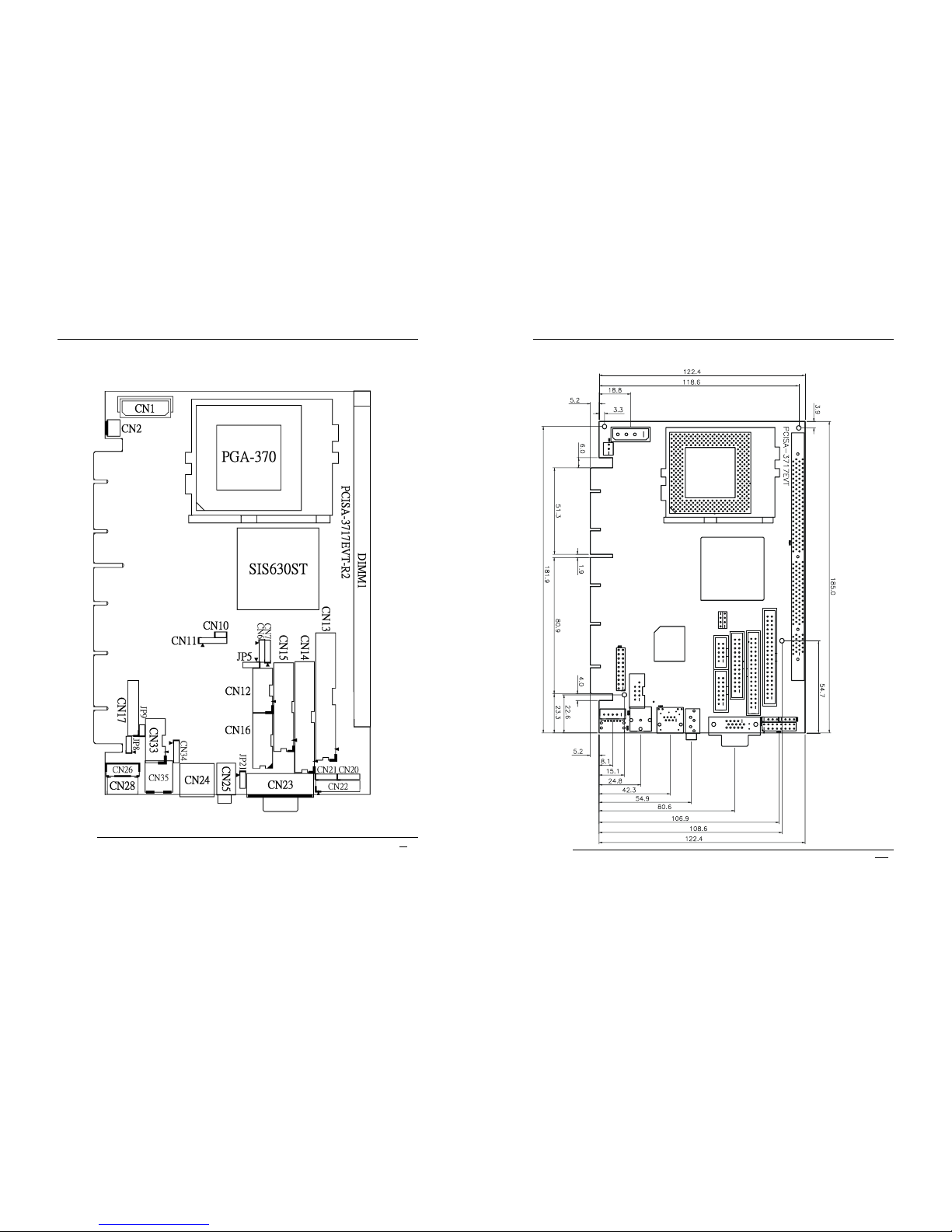
2.1 PCISA-3717EVT-R2 's Layout
< please, refer to the next page >
PCISA-3717EVT-R2 Socket 370 Celeron
TM
, Pentium III ®
& Tualatin Processor with Ethernet , VGA( Dual Display ) ,
TV-Out , Audio Board
9
2.1 PCISA-3717EVT-R2 's Layout
PCISA-3717EVT-R2 Socket 370 CeleronTM , Pentium III ®
& Tualatin Processor with Ethernet , VGA( Dual Display ) ,
TV-Out ,Audio Board
10
2.2 PCISA-3717EVT-R2 's Dimensions ( Unit :mm )
PCISA-3717EVT-R2 Socket 370 Celeron
TM
, Pentium III ®
& Tualatin Processor with Ethernet , VGA( Dual Display ) ,
TV-Out , Audio Board
11
2.3 Unpacking Precautions
Some components on PCISA-3717EVT-R2 are very sensitive to
static electric charges and can be damaged by a sudden rush of
power. To protect it from unintended damage, be sure to follow
these precautions:
Ground yourself to remove any static charge before touching your
PCISA-3717EVT-R2. You can do it by using a grounded wrist strap
at all times or by frequently touching any conducting materials that is
connected to the ground.
Handle your PCISA-3717EVT-R2 by its edges. Don’t touch IC chips,
leads or circuitry if not necessary.
Do not plug any connector or jumper while the power is on.
Do not put your PCISA-3717EVT-R2 unprotected on a flat surface
because it has components on both sides.
PCISA-3717EVT-R2 Socket 370 CeleronTM , Pentium III ®
& Tualatin Processor with Ethernet , VGA( Dual Display ) ,
TV-Out ,Audio Board
12
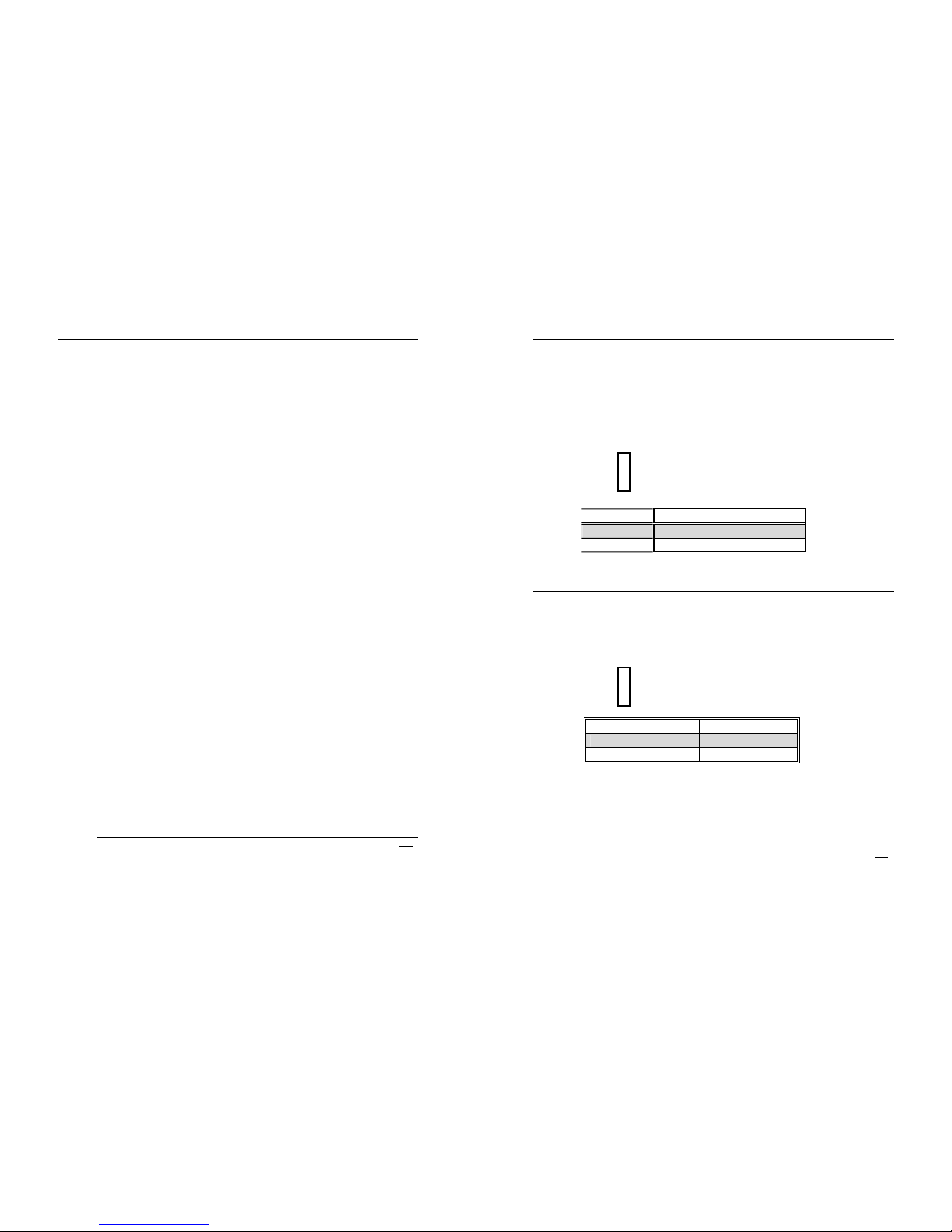
2.4 Clear CMOS Setup
If you forget the CMOS password, you can clear or reset it by
closing the
JP5
. After JP5(1-2) is closed, turn on the power for
about 3 seconds then turn it off and open the JP5(1-2). Now,
the password has been cleared from your CMOS.
•
JP5 : Clear CMOS Setup
1
2
3
JP5 DESCRIPTION
2-3 Normal Operation
1-2 Clear CMOS Setup
2.5 COM2 RS-232/422,485 Selection ( Option )
•
JP21 : COM2 Mode Selection
1
2
3
JP21 DESCRIPTION
1-2 RS232
2-3
RS422/RS485
** 2-3 RS422 / RS485 ( Option )
PCISA-3717EVT-R2 Socket 370 Celeron
TM
, Pentium III ®
& Tualatin Processor with Ethernet , VGA( Dual Display ) ,
TV-Out , Audio Board
13
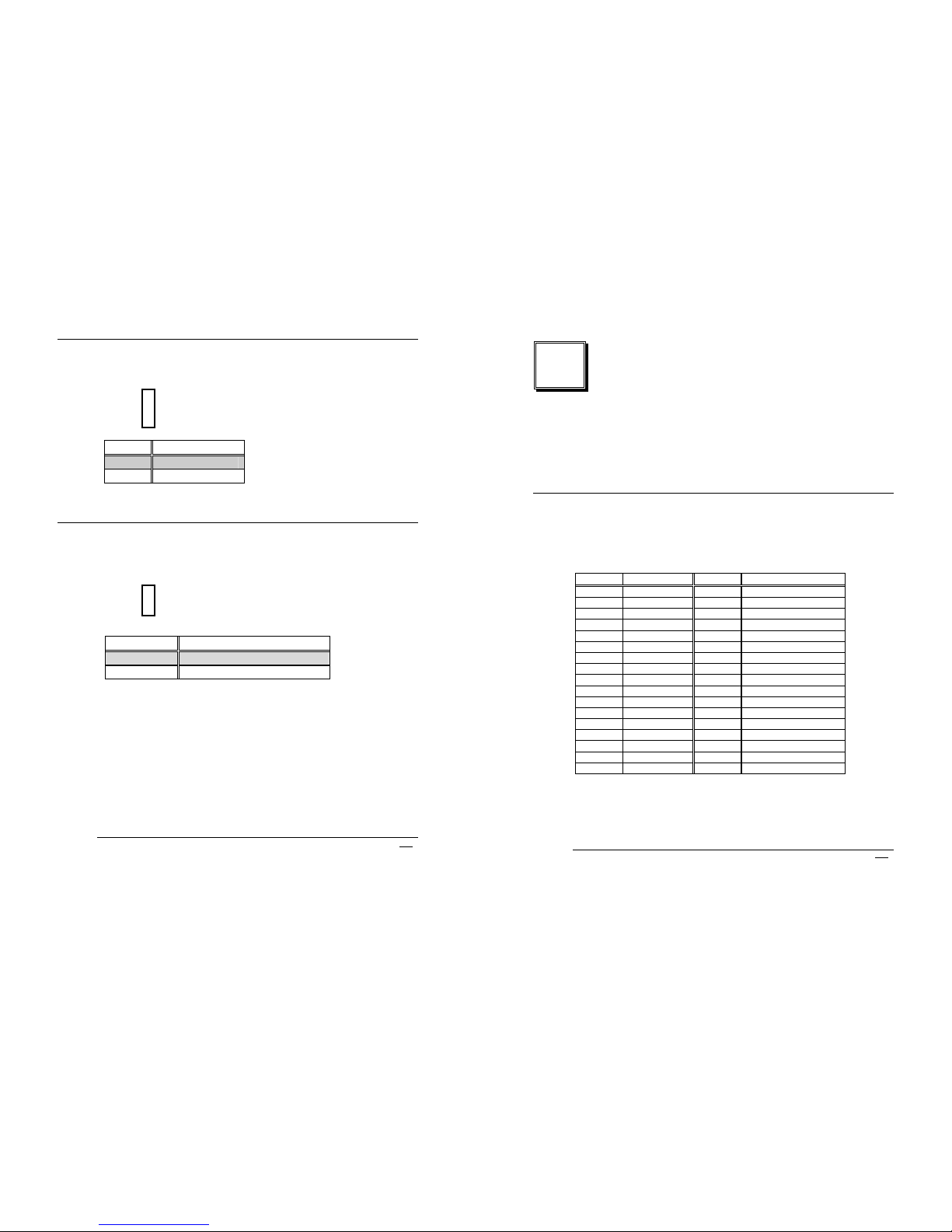
2.6 Keyboard Power Selection
•
JP8 : Keyboard Power Selection
1
2
3
JP8 DESCRIPTION
1-2 VCC
2-3
5VSB
2.7 AT or ATX Power Setting
•
JP9 : AT or ATX Power Selection
1
2
JP9 DESCRIPTION
Short For AT Power
Open
For ATX Power
*To use AT power , JP9 must be Short to avoid
Keyboard / Mouse fail
*To use ATX power , JP9 must be Open to avoid
boot fail
PCISA-3717EVT-R2 Socket 370 CeleronTM , Pentium III ®
& Tualatin Processor with Ethernet , VGA( Dual Display ) ,
TV-Out ,Audio Board
14
3
Connection
This chapter describes how to connect peripherals, switches and
indicators to the PCISA-3717EVT-R2 board.
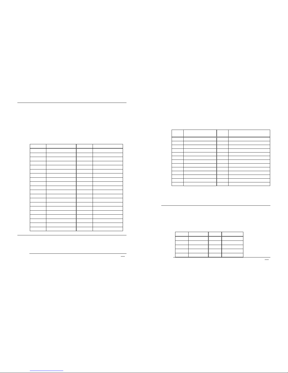
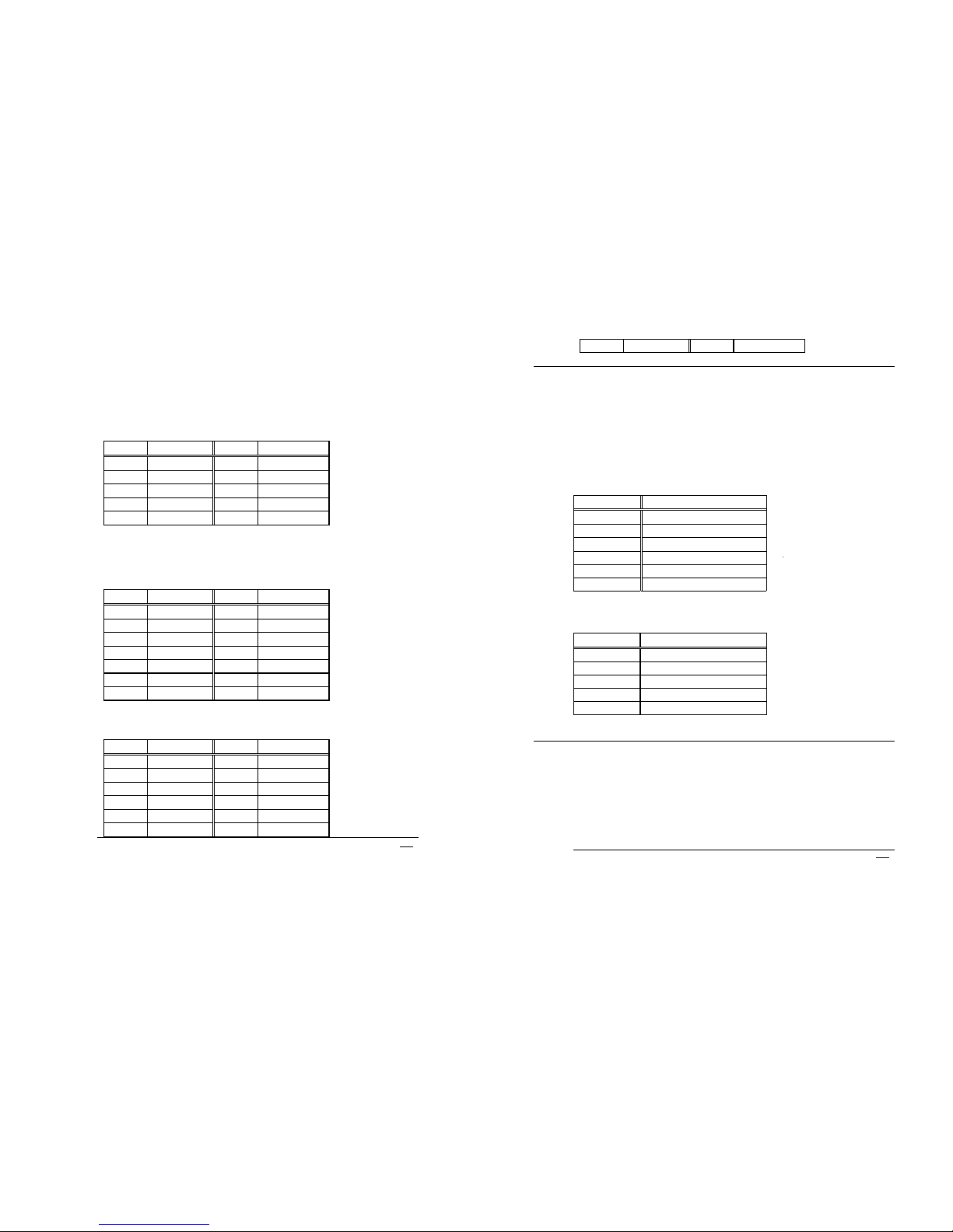
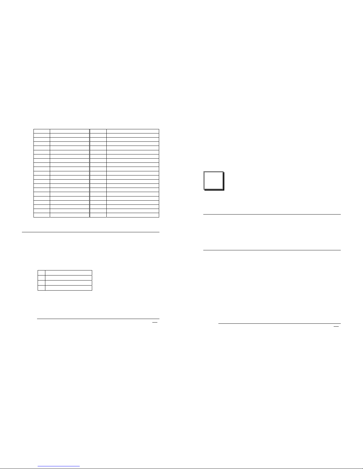
3.1 Floppy Disk Drive Connector
PCISA-3717EVT-R2 board is equipped with a 34-pin daisy-chain
driver connector cable.
•
CN14 : FDD CONNECTOR
PIN NO. DESCRIPTION PIN NO. DESCRIPTION
1 GROUND 2 REDUCE WRITE
3 GROUND 4 N/C
5 GROUND 6 N/C
7 GROUND 8 INDEX#
9 GROUND 10 MOTOR ENABLE A#
11 GROUND 12 DRIVE SELECT B#
13 GROUND 14 DRIVE SELECT A#
15 GROUND 16 MOTOR ENABLE B#
17 GROUND 18 D4IRECTION#
19 GROUND 20 STEP#
21 GROUND 22 WRITE DATA#
23 GROUND 24 WRITE GATE#
25 GROUND 26 TRACK 0#
27 GROUND 28 WRITE PROTECT#
29 GROUND 30 READ DATA#
31 GROUND 32 SIDE 1 SELECT#
33 GROUND 34 DISK CHANGE#
PCISA-3717EVT-R2 Socket 370 Celeron
TM
, Pentium III ®
& Tualatin Processor with Ethernet , VGA( Dual Display ) ,
TV-Out , Audio Board
15
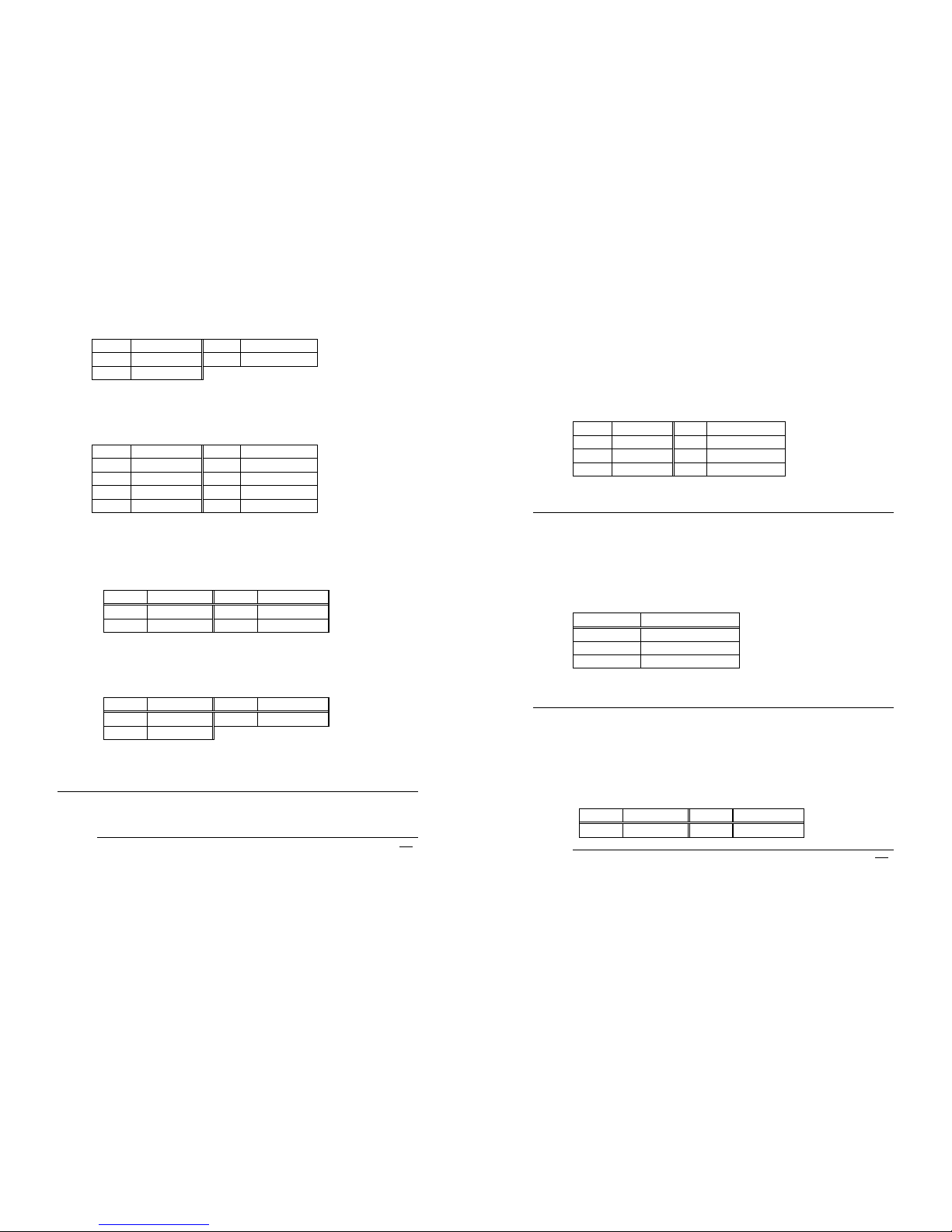
3.2 PCI E-IDE Disk Drive Connector
You can attach two IDE (Integrated Device Electronics) hard disk
drives to the PCISA-3717EVT-R2 IDE controller .The maximal
data transfer rate is 66MB/s. In this case ,cable total length shall
not exceed 0.46m ( 18in ).
CN13 ( 40Pin 2.54mm IDE) : Primary IDE Connector
•
CN13 : IDE Interface Connector
PIN NO. DESCRIPTION PIN NO. DESCRIPTION
1 RESET# 2 GND
3 DATA 7 4 DATA 8
5 DATA 6 6 DATA 9
7 DATA 5 8 DATA 10
9 DATA 4 10 DATA 11
11 DATA 3 12 DATA 12
13 DATA 2 14 DATA 13
15 DATA 1 16 DATA 14
17 DATA 0 18 DATA 15
19 GND 20 N/C
21 IDE DRQ 22 GND
23 IOW# 24 GND
25 IOR# 26 GND
27 IDE CHRDY 28 GND
29 IDE DACK 30 GND
31 INTERRUPT 32 N/C
33 SA 1 34 N/C
35 SA 0 36 SA 2
37 HDC CS0# 38 HDC CS1#
39 HDD ACTIVE# 40 GND
3.3 Parallel Port
This port is usually connected to a printer, The PCISA-3717EVTR2 includes an on-board parallel port, accessed through a 26-pin
PCISA-3717EVT-R2 Socket 370 Celeron
TM
, Pentium III ®
& Tualatin Processor with Ethernet , VGA( Dual Display ) ,
TV-Out ,Audio Board
16
flat-cable connector CN15.
•
CN15 : ( LPT1 ) Parallel Port Connector
Pin Description Pin Description
1 STROBE# 2 AUTO FORM FEED #
3 DATA 0 4 ERROR#
5 DATA 1 6 INITIALIZE
7 DATA 2 8 PRINTER SELECT LN#
9 DATA 3 10 GND
11 DATA 4 12 GND
13 DATA 5 14 GND
15 DATA 6 16 GND
17 DATA 7 18 GND
19 ACKNOWLEDGE 20 GND
21 BUSY 22 GND
23 PAPER EMPTY 24 GND
25 PRINTER SELECT 26 N/C
3.4 Serial Ports
The PCISA-3717EVT-R2 offers Two high speed NS16C550
compatible UARTs with Read/Receive 16 byte FIFO serial ports
(COM1/COM2).
•
CN12 : Serial Port 2x5 pin header Connector (COM1)
Pin No. Description Pin No. Description
1 DCD 2 DSR
3 RXD 4 RTS
5 TXD 6 CTX
7 DTR 8 RI
9 GND 10 NC
PCISA-3717EVT-R2 Socket 370 Celeron
TM
, Pentium III ®
& Tualatin Processor with Ethernet , VGA( Dual Display ) ,
TV-Out , Audio Board
17
•
CN16 : Serial Port 2x7 pin header Connector (COM2)
COM2 Support Three Mode : RS232, RS422/RS485
( For 2x5 pin header Connector )
RS232 Mode
Pin No. Description Pin No. Description
1 DCD 2 DSR
3 RXD 4 RTS
5 TXD 6 CTX
7 DTR 8 RI
9 GND 10 NC
RS422 / RS485 Mode ( Option )
( For 2x7 pin header Connector )
RS422 Mode
Pin No. Description Pin No. Description
1 2
3 4
5 6
7 8
9 10
11 TX+ 12 TX13 RX+ 14 RX-
( For 2x7 pin header Connector )
RS485 Mode
Pin No. Description Pin No. Description
1 2
3 4
5 6
7 8
9 10
11 12
PCISA-3717EVT-R2 Socket 370 CeleronTM , Pentium III ®
& Tualatin Processor with Ethernet , VGA( Dual Display ) ,
TV-Out ,Audio Board
18
13 RX+ 14 RX-
3.5 Keyboard/Mouse Connector
The PCISA-3717EVT-R2 provides one external keyboard &
mouse ,one extra keyboard connectors.
•
CN28 : Extended Keyboard & PS/2 Mouse 6-pin Mini Din
Connector
PIN NO. DESCRIPTION
1 KB DATA
2 MS DATA
3 GND
4 VCC
5 KB CLOCK
6 MS CLOCK
•
CN26 : 5-pin Header extra Keyboard Connector
PIN NO. DESCRIPTION
1 KB CLOCK
2 KB DATA
3 N/C
4 GND
5 +5V
3.6 External Switches and Indicators
There are several external switches and indicators for monitoring
and controlling your CPU board. All the functions are in the
CN17 connector.
PCISA-3717EVT-R2 Socket 370 Celeron
TM
, Pentium III ®
& Tualatin Processor with Ethernet , VGA( Dual Display ) ,
TV-Out , Audio Board
19
•
CN17 : Multi Panel
PIN NO. DESCRIPTION PIN NO. DESCRIPTION
1. SPEAKER - 11 POWER-LED +
2. N/C 12 N/C
3. N/C 13 POWER-LED -
4. SPEAKER +5V 14 KEYLOCK+
5. RESET SW 15 KEYLOCK -
6. RESET SW GND 16 GND
7. IDE LED - 17 N/C
8. IDE LED+ 18 ATX POWER PSON#
9. ATX POWER
BUTTON +
19 ATX 5VSB
10. ATX POWER
BUTTON GND
20 ATX 5VSB
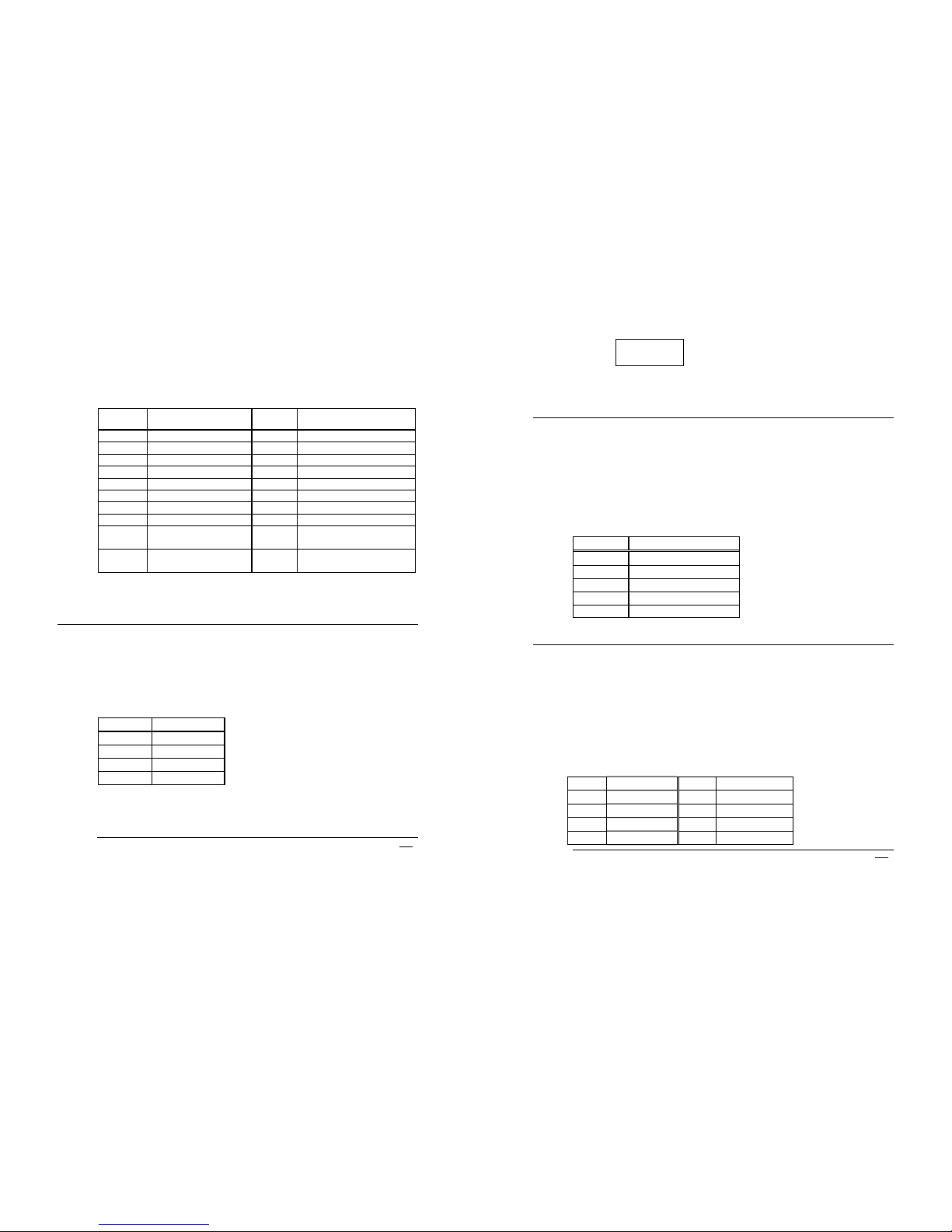
3.7 USB Port Connector
The PCISA-3717EVT-R2 has built-in two USB ports for the future
new I/O bus expansion.
• CN6,7: Pin Header USB Connectors
PIN NO. Description
1 VCC
2 USBD03 USBD0+
4 GND
4 3 2 1 CN7 ( USB 0 )
PCISA-3717EVT-R2 Socket 370 Celeron
TM
, Pentium III ®
& Tualatin Processor with Ethernet , VGA( Dual Display ) ,
TV-Out ,Audio Board
20
1 2 3 4 CN6 ( USB 1 )
3.8 IrDA Infrared Interface Port
PCISA-3717EVT-R2 built-in IrDA port supports Serial Infrared
(SIR) or Amplitude Shift Keyed IR (ASKIR) interface. If you want
to use the IrDA port, you have to configure the FIR or ASKIR
model in the BIOS’s Peripheral Setup’s COM2. Then the normal
RS-232 COM2 will be disabled.
•
CN11 : IrDA Connector
PIN NO. DESCRIPTION
1 VCC
2 N/C
3 IR-RX
4 GND
5 IR-TX
3.9 VGA Connector
The built-in 15-pin D-Type and 10-pin 2x5 pin header VGA
connector support dual display can be connected directly to your
monochrome CRT monitor as well as high resolution color CRT
monitor.
•
CN23 : 15-pin Female VGA Connector
( Primary Display )
1 RED 2 GREEN
3 BLUE 4 N/C
5 GND 6 GND
7 GND 8 GND
9 VCC 10 GND
PCISA-3717EVT-R2 Socket 370 Celeron
TM
, Pentium III ®
& Tualatin Processor with Ethernet , VGA( Dual Display ) ,
TV-Out , Audio Board
21
11 N/C 12 DDC DAT
13 HSYNC 14 VSYNC
15 DDC CLK
• CN33 : 10-pin Pin Header VGA Connector
( Secondary Display )
1 RED 2 DDC CLK
3 GREEN 4 DDC DAT
5 BLUE 6 GND
7 HSYNC 8 GND
9 VSYNC 10 GND
•
CN34 : TV Connector (S-video)
( Secondary Display )
Pin No. Description Pin No. Description
1 TV-Y 2 GND
3 GND 4 TV-C
•
CN35 : TV Connector (Composite AV )
( Secondary Display )
Pin No. Description Pin No. Description
1 TV-CVBS 2 GND
3 GND
3.10 LAN RJ45 Connector
PCISA-3717EVT-R2 is equipped with one 10/100Mbps Ethernet
PCISA-3717EVT-R2 Socket 370 Celeron
TM
, Pentium III ®
& Tualatin Processor with Ethernet , VGA( Dual Display ) ,
TV-Out ,Audio Board
22
Controller. You can connect it to your LAN through RJ45
connector. The pin assignments are as follows.
•
CN24 : LAN RJ45 Connector
1 TX+ 5. N/C
2 TX- 6. RX-
3. RX+ 7. N/C
4. N/C 8. N/C
3.11 Fan Connector
The PCISA-3717EVT-R2 provides one CPU cooling fan
connector. This connector can supply 12V/500mA to the cooling
fan.
•
CN2 : CPU Fan Connector
PIN NO. DESCRIPTION
1 GND
2 +12V
3 Fan Sensor
3.12 Temperature Sensor Connector
You can connect external temperature sensor to this connector.
•
CN10 : Temperature Sensor Connector
** Use 10K Ohm Temperature register
sensor
Pin No. Description Pin No. Description
1 THER-DA 2 GND
PCISA-3717EVT-R2 Socket 370 Celeron
TM
, Pentium III ®
& Tualatin Processor with Ethernet , VGA( Dual Display ) ,
TV-Out , Audio Board
23
3.13 Audio CD IN
This is used to connect to the CD-Out from CD-ROM player.
• CN21 : Audio CD IN ( 2.54mm )
Pin No. Description Pin No. Description
1 CD IN_R 2 GND
3 GND 4 CD IN_L
3.14 Audio Line OUT
This output normally support direct line-out from audio chip.
It will only provide 6W output when the optional amplifiers is
installed .
• CN25 : Left/Right Audio Output Connector for
Headphone or By optional amplifier Speaker
Output .
1. GROUND
2. LEFT SIGNAL ( SPK LEFT )
3. NC
4. RIGHT SIGNAL ( SPK RIGHT )
5. NC
3.15 Speaker OUT ( Reserved )
•
CN20 : Optional Speaker out .
( Two 6W stereo power amplifiers )
PCISA-3717EVT-R2 Socket 370 Celeron
TM
, Pentium III ®
& Tualatin Processor with Ethernet , VGA( Dual Display ) ,
TV-Out ,Audio Board
24
1. RIGHT SIGNAL
2. GND
3. GND
4. LEFT SIGNAL
3.16 Audio Panel
One line-out ( 2 different pin assignments ),one line-in and one
mic-in are supported. All these output are from audio chip
without being amplified.
•
CN22 : Audio Panel
Pin Description Pin Description
1 Line Out R 2 GND
3 Line Out L 4 GND
5 Line Out R 6 Line Out L
7 GND 8 GND
9 Line In R 10 Line In L
11 GND 12 GND
13 NC 14 NC
15 MIC In 16 GND
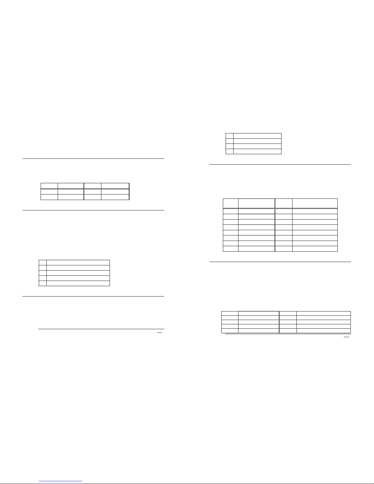
3.17 CompactFlash™ Storage Card Socket
The PCISA-3717EVT-R2 configures CompactFlash™ Storage
Card in IDE Mode.
It will use IDE Secondary channel when CompactFlash™ card
is plugged in.
•
CN31 : CompactFlash™ Storage Card Socket pin assignment
PIN NO DESCRIPTION PIN NO DESCRIPTION
1 GROUND 26 CARD DETECT1
2 D3 27 D11
3 D4 28 D12
4 D5 29 D13
PCISA-3717EVT-R2 Socket 370 Celeron
TM
, Pentium III ®
& Tualatin Processor with Ethernet , VGA( Dual Display ) ,
TV-Out , Audio Board
25
5 D6 30 D14
6 D7 31 D15
7 CS1# 32 CS3#
8 N/C 33 N/C
9 GROUND 34 IOR#
10 N/C 35 IOW#
11 N/C 36 OBLIGATORY TO PULL HIGH
12 N/C 37 IRQ15
13 VCC 38 VCC
14 N/C 39 MASTER/SLAVE
15 N/C 40 N/C
16 N/C 41 RESET#
17 N/C 42 IORDY
18 A2 43 N/C
19 A1 44 OBLIGATORY TO PULL HIGH
20 A0 45 ACTIVE#
21 D0 46 PDIAG#
22 D1 47 D8
23 D2 48 D9
24 N/C 49 D10
25 CARD DETECT2 50 GROUND
3.18 Power Connector
The PCISA-3717EVT-R2 can work without back-plane , while
attaching external power to this connector .
•
CN1: Power Supply Connector
1. +5V
2. GND
3. GND
4. +12V
PCISA-3717EVT-R2 Socket 370 Celeron
TM
, Pentium III ®
& Tualatin Processor with Ethernet , VGA( Dual Display ) ,
TV-Out ,Audio Board
26
4
AWARD BIOS SETUP
4.1 Introduction
This manual discusses Award's Setup program built into the ROM BIOS. The
Setup program allows users to modify the basic system configuration. This
special information is then stored in battery-backed RAM so that it retains the
Setup information when the power is turned off.
4.2 Starting Setup
The Award BIOS is immediately activated when you first power on the computer.
The BIOS reads the system information contained in the CMOS and begins the
process of checking out the system and configuring it. When it finishes, the BIOS
will seek an operating system on one of the disks and then launch and turn
control over to the operating system.
While the BIOS is in control, the Setup program can be activated in one of two
ways:
1. By pressing <Del> immediately after switching the system on, or
2. by pressing the <Del> key when the following message appears briefly at the
bottom of the screen during the POST (Power On Self Test).
Press DEL to enter SETUP.
 Loading...