

Page 1
Installation Instructions
I DIRECT DRIVE BLOWER
PA95/PAPC
PA55/PAPA SERI ES
SINGLEPACKAGEAIRCONDITIONERS
ELECTRICCOOL/
ELECTRICHEAT(OPTIONAL)c
TABLEOFCONTENTS
1. Safety Labeling and Signal Words .......................... 2
Danger,Warningand Caution .................................... 2
2. Safe Installation Requirements ....................... 2
3. Locating The Unit .................................. 2
Clearances ............................................... 2
Dimensions................................................... 2
MinimumClearancesto CombustibleConstruction..................... 3
Installation ................................................... 3
InstallingDuctCollars ........................................ 3
CondensateDrain ............................................. 4
4. Electrical Wiring .................................... 4
Ground Connections........................................... 4
LineVoltageWiring ............................................. 4
Unit Disconnect ............................................... 4
Converting230V Unitsto 208V .................................... 4
LowVoltageWiring ............................................ 4
ThermostatConnections......................................... 5
FieldInstalledEquipment ........................................ 5
5. Electric Heat Installation ............................. 6
GeneralInformation ................................ 6
AdjustingTherrnostatAnticipator ................................. 6
UmitControls .............................................. 6
TimeDelayOperation ................................... 6
Staging .................................................. 6
InstallHeater ................................................. 6
HeaterWiring ........................................... 6
Grounding ................................................ 6
InstallingWiring .......................................... 7
Unit DisconnectBreaker ......................................... 8
RainShield Installation ......................................... 8
6. Air Distribution System .............................. 9
Ductwork .................................................... 9
DuctworkInsulation ............................................ 9
DuctwotkConnections.......................................... 9
Fi_ers .............................. 9
7. Start-up Procedures ............................... 10
FinalElectricalCheck ................ 10
CirculaUngAirBlower .......................................... 10
Determining8_owerSpeed.......... 10
Steed Taos ............................ 10
Cooling andAuxiliary Electric Strip Heat ............................ tO
CheckBeforeStarting ...................... 10
CirculatingAir Blower ..................... 11
Cooling ................................................... 11
AuxiliaryHeating ......................... 11
TemperatureRiseCheck ..................... 11
SequenceofOperation ......................................... tt
CoolingMode:Energized(R,G,Yt_ De-energized_N/At................ 11
8. Operation .......................................... 11
Scroll Acti- Cycle Timer(WhereApplicable}.......................... 11
TurningTheUnit Off ....................... 12
ThermostatFan SwitchOperation ................................. 12
AdjustingRoomTemperatures ...... 12
13. Maintenance .................................. 12
MonthlyMaintenanceandInspectionChecks ........................ 12
Air Filters ................................................ 12
CoolingSeasonChecks(Monthly)................................. 12
CondenserCoil ........................................... 12
CondensateDrain............................................ 12
AnnualMaintenanceand Inspection ............................... 12
Condense"FanMotor ......................................... 12
CirculatingAir Blower ......................................... 12
Printed in U.S.A. 426 011001 02
2/20/96
Page 2
1. Safetv Labelinq and Siflnal Words
Danger,Warningand Caution
ThesignalwordsDANGER,WARNINGandCAUTIONareusedtoidentifylevelsofhaz-
ard seriousness.The signalword DANGERis onlyusedon productlabelsto signifyan
immediatehazard.The signalwords WARNINGandCAUTIONwill beused on product
labelsandthroughoutthis manualand othermanualsthat mayapplyto the product.
2. Safe Installation Requirem ents
CAUTION
Do NOToperate unit in a corrosive atmosphere containing chlorine,
fluorine, or any other corrosive chemicals.
Installation or repairs made by unqualified persons can result
in hazards to you and others. Installation MUST conform with
local building codes or, in the absence of local codes, with the
National Electrical Code NFPA70-1990 or current edition.
The information contained in this manual is intended for use
by a qualified service technician familiar with safety proce-
dures and equipped with the proper tools and test instru-
ments.
Failure to carefully read and follow all instructions in this
manual can result in unit malfunction, property damage, per-
sonal injury and/or death.
• Seal supply and return air ducts.
• Check to see that filters are installed correctly and are the proper
type and size.
NOTE:It isthepersonalresponsibilityandobligationofthecustomertocontactaqualified
installerto ensurethat theinstallationisadequateand conformsto governingcodesand
ordinances.
3. Locatinq & Installinq The Unit
The unitis designedfor outdoorinstallationonly.Placetheunit ona platformat ground
level. The unitmay be installedon a concreteslab of 48" (1219mm)x 48" (1219mm)
dimensions. Cement blocks on a 3" sand footing willalso work. The slab or blocks
SHOULDNOT bein contactwith any partofthe structure. Checklocalcodescovering
zoning,noise, platforms,etc..
Ifpracticalavoid locatingnexttofreshair intakes,ventorbedroomwindows. Noisemay
carryintotheopeningsand disturbpeopleinside.
Avoid installationsunderroof overhangswithoutguttering. Waterdrainingfromthe roof
ontotheunitcould produceexcessivenoise,andmaycauseicetobuildupon coil orfan.
Placementoftheunitshouldbe inawelldrainedareaortheunit MUSTbesupportedhigh
enoughso runoffwillnotenterthe unit.
Do not locate unitwhereheat, lint orexhaustfumeswill bedischargedon unit (asfrom
dryervents.)
Clearances
Minimum clearances,as specified in FIGURE1, MUSTbe maintainedfrom adjacent
structuresto provideadequateaircirculationand roomfor service personnel.
While minimumclearancesare acceptablefor safetyreasons,theymay not allowade-
quateaircirculationaroundtheunitforproperoperation.Wheneverpossible,itisdesirable
toallow additionalclearance,especiallyaroundthe condenserinletand dischargeopen-
ings.
Do NOTinstallthe unitin arecessedorconfinedareathat will permitdischargedairfrom
thecondensertorecirculatetothe condenserinlet.
Dimensions
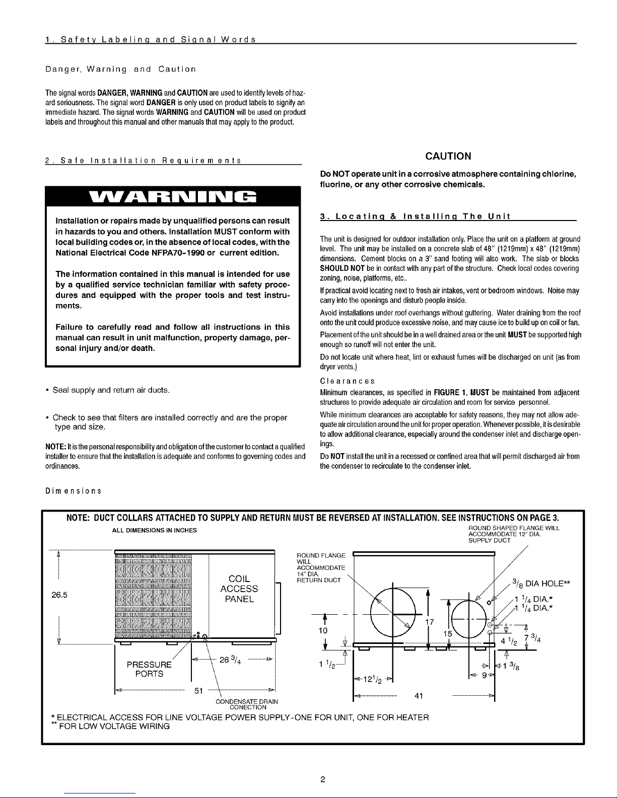
NOTE: DUCT COLLARS ATTACHED TO SUPPLY AND RETURN MUST BE REVERSED AT INSTALLATION. SEE INSTRUCTIONS ON PAGE 3.
ALL DIMENSIONS IN iNCHES ROUND SHAPED FLANGE WiLL
ACCOMMODATE 12" DIA.
SUPPLY DUCT
t
26.5
COIL
ACCESS
PANEL
ROUND FLANGE
WILL
ACCOMMODATE
14_ DIA.
RETURN DUCT
T m
10
\ 41
CONDENSATE DRAIN
CONECTION
* ELECTRICAL ACCESS FOR LINE VOLTAGE POWER SUPPLY-ONE FOR UNIT, ONE FOR HEATER
** FOR LOW VOLTAGE WIRING
DIA HOLE**
_/4 DIA.*
_/4 DIA.*
3/4
Page 3
Minimum Clearances to Combustible Construction
SERVICE ACCESS CLEARANCES
Blower Access Panel Side .......................... 30" (762mm)
Electrical Access Panel Side ........................ 30" (762mm)
OPERATIONAL CLEARANCES
Combustible Base
(Wood or Class A, B or C
roof covering material) ......................... 0"
Supply and Return Air Ducts ................................. 0"
Duct Connection Side
Clearance between Overhang
and Top of Unit ..................... 48" (1219mm)
Clearance around Condenser Coil area to wall or shrubs ........ 10"
I
FIGURE 1
I Minimum Clearances and Access Panels
I
Overhang
Evaporator 48" Minimum Overhang Clearance
Access Panel
f 10"around
condenser
coil area
6" Blower/Electrical
Access Panel
Cover Plate
Installation
CAUTION
The unit must be installed as level as possible, with a maximau
slope no greater than 1/8" per foot (10mm per meter). For side to side
leveling, the condensate drain side of the unit MUST always be lower
to provide proper drainage.
The unit MUST be situated in such away as to provide safe access
for servicing.
The platform may be made of either concrete or pressure treated
wood and MUST be level and strong enough to support the unit's
weight.
Position platform separate from the building's foundation.
install in a well-drained area, with the top surface of the platform
high enough above grade level to allow installation of a conden-
sate drain trap. See FIGURE4
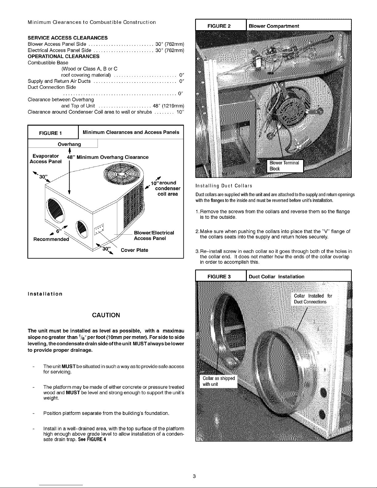
FIGURE 2 Blower Compartment
Installing Duct Collars
Ductcollarsaresuppliedwiththe unitand areattachedtothesupplyandreturnopenings
withthe flanges to theinsideand mustbe reversedbeforeunit'sinstallation.
1.Remove the screws from the collars and reverse them so the flange
isto the outside.
2. Make sure when pushing the collars into place that the "V" flange of
the collars seats into the supply and return holes securely.
3. Re-install screw in each collar so it goes through both of the holes in
the collar end. It does not matter how the ends of the collar overlap
in order to accomplish this.
FIGURE 3 I Duct Collar Installation I
Page 4
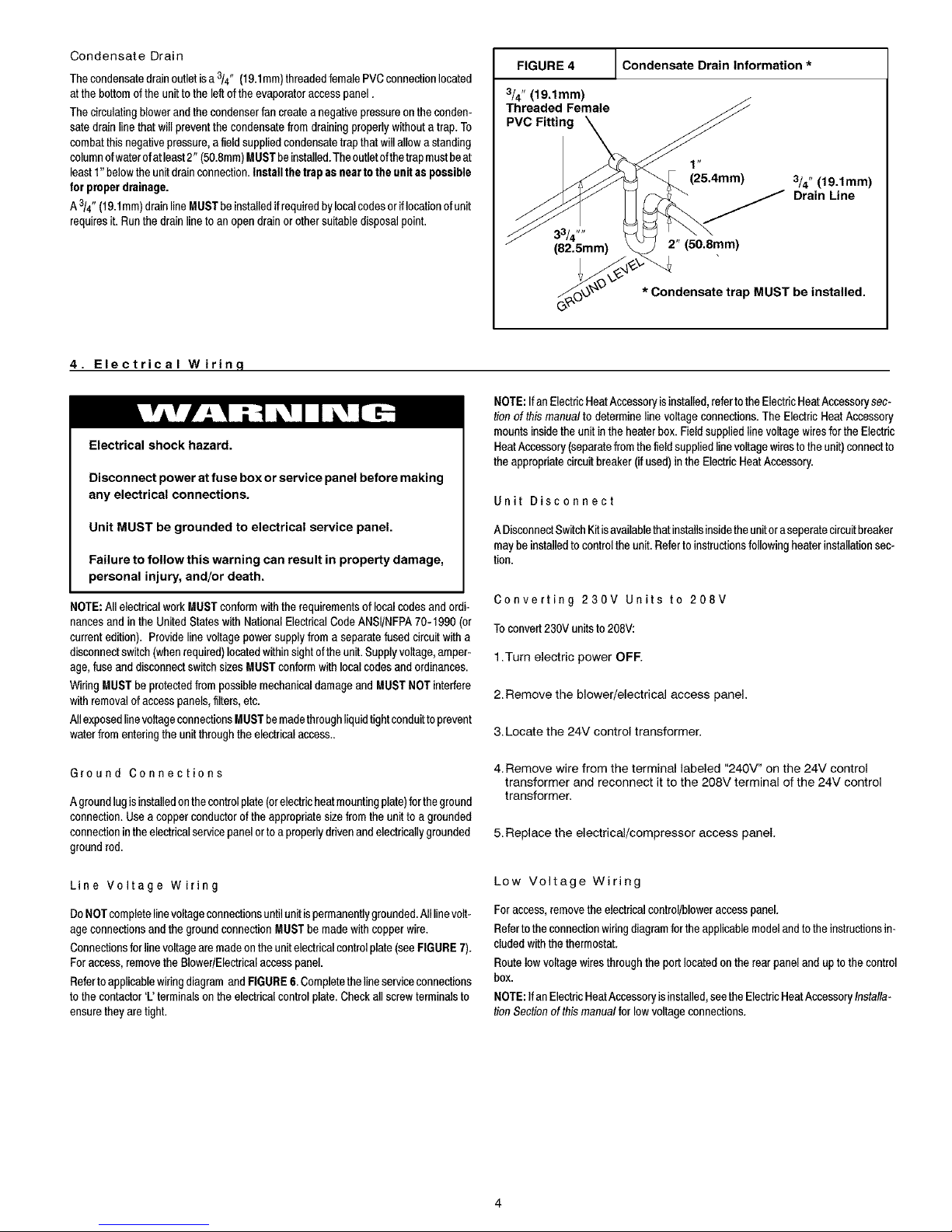
CondensateDrain
Thecondensatedrainoutletisa 314" (19.1mm)threadedfemalePVCconnectionlocated
atthe bottom of theunittothe leftof theevaporatoraccesspanel.
Thecirculatingblowerandthe condenserfancreatea negativepressureonthe conden-
satedrain linethat will preventthe condensatefromdrainingproperlywithouta trap.To
combatthisnegativepressure,afield suppliedcondensatetrapthat willallow astanding
columnofwaterofat least2" (50.8mm)MUSTbeinstalled.Theoutletofthetrapmustbeat
least1"belowthe unitdrainconnection.Install thetrapas nearto theunit aspossible
for properdrainage.
A3/4" (19.1mm)drainline MUSTbe installedifrequiredbylocalcodesor iflocationof unit
requiresit. Runthe drainlineto an open drainor othersuitabledisposalpoint.
FIGURE 4
3/4" (19.1mm)
Threaded Female
PVC Fitting
Condensate Drain Information *
1"
(25.4mm)
3/4" (19.1mm)
Drain Line
33/4 ""
(82.5mm) 2" (50.8mm)
_,_kv * Condensate trap MUST be installed.
4. Electrical Wirinq
Electrical shock hazard.
Disconnect power at fuse box or service panel before making
any electrical connections.
Unit MUST be grounded to electrical service panel.
Failure to follow this warning can result in property damage,
personal injury, and/or death.
NOTE:All electricalworkMUST conformwiththerequirementsof localcodesandordi-
nancesand in the UnitedStates with NationalElectricalCodeANSI/NFPA70-1990 (or
currentedition). Provide linevoltagepowersupplyfrom aseparatefused circuitwitha
disconnectswitch(whenrequired)locatedwithinsight ofthe unit.Supplyvoltage,amper-
age,fuseanddisconnectswitchsizesMUST conformwithlocalcodes and ordinances.
WiringMUSTbe protectedfrompossiblemechanicaldamageandMUSTNOT interfere
with removalofaccesspanels,filters,etc.
AllexposedlinevoltageconnectionsMUSTbemadethroughliquidtightconduittoprevent
waterfromenteringthe unitthroughthe electricalaccess..
Ground Connections
Agroundlugisinstalledonthecontrolplate(orelectricheatmountingplate)fortheground
connection.Use acopperconductorofthe appropriatesizefromthe unitto a grounded
connectionintheelectricalservicepanelortoa properlydrivenandelectricallygrounded
groundrod.
Line Voltage Wiring
DoNOTcompletelinevoltageconnectionsuntilunitispermanentlygrounded.Alllinevolt-
ageconnectionsandthegroundconnectionMUSTbemade withcopper wire.
Connectionsfor linevoltagearemadeon the unitelectricalcontrolplate(seeFIGURE7).
For access,removethe Blower/Electricalaccesspanel.
Refertoapplicablewiringdiagram andFIGURE6. Completetheline serviceconnections
tothe contactor'L' terminalson theelectricalcontrolplate.Check allscrewterminalsto
ensuretheyare tight.
NOTE:If an ElectricHeatAccessoryisinstalled,refertotheElectricHeatAccessorysec-
tion of thismanual to determinelinevoltage connections.The ElectricHeat Accessory
mountsinsidethe unitin the heater box.FieldsuppliedlinevoltagewiresfortheElectric
HeatAccessory(separatefromthe fieldsuppliedlinevoltagewirestothe unit)connectto
theappropriatecircuitbreaker (ifused)in the ElectricHeatAccessory.
Unit Disconnect
ADisconnectSwitchKitisavailablethatinstallsinsidetheunitoraseperatecircuitbreaker
maybeinstalledtocontrolthe unit.Refertoinstructionsfollowingheaterinstallationsec*
tion.
Converting 230V Units to 208V
Toconvert230V unitsto 208V:
1.Turn electric power OFF.
2. Remove the blower/electrical access panel.
3. Locate the 24V control transformer.
4. Remove wire from the terminal labeled "240V" on the 24V control
transformer and reconnect it to the 208V terminal of the 24V control
transformer.
5. Replace the electrical/compressor access panel.
Low Voltage Wiring
For access,removethe electricalcontrol/bloweraccesspanel.
Refertothe connectionwiringdiagramfortheapplicablemodelandtothe instructionsin-
cludedwith the thermostat.
Routelowvoltagewiresthroughthe port locatedon the rearpaneland upto thecontrol
box.
NOTE:If an ElectricHeatAccessoryisinstalled,seetheElectricHeatAccessoryInstalla-
tion Sectionof thismanualfor lowvoltage connections.
Page 5

ThermostatConnections
Thelocationofthethermostathasanimportanteffectontheoperationofthe unit.Seethe
thermostatinstructionsfor properconnection. See FIGURE5for LowVoltageWireHar-
nessConnections
Field Installed Equipment
Wiringtobedoneinthefieldbetweentheunitandotherdevices,or betweenseparatede-
viceswhicharefieldinstalledandlocated,MUSTNOTexceedthetemperaturelimitations
fortypeT wireandMUSTbeinstalledaccordingtothemanufacturer'sinstructionsforthe
devices.
J Electronic Thermostat Low Voltage Wiring
FIGURE 5 Harness Connection Diagram
Typical Thermostat Subbase
[,q [?] [R,]
I I I I I
I I I I I
, = = , (when used)
I I I I I
i i , , [W'h
[Blue] [Green] [Red] [Yellow] ite]
Com Fan 24V Comp Elect.
(when Cool Heat
used) Acces.
Unit Low Voltage Wiring Harness.
FIGURE 6 J Typical Connections at Unit
"F_'I
I
II
II
aCT I '
I I
I I
I
I
USE CO PPER CONDUCTORS ONLY
208/Z30V 60HZ 7PH
I
I
I
I
I
] • I
J
F _ 3 1
'1 K_ I I\ I
' -_ I I 'l'' I_
I BL I J GND L__ R__/_R
I
L=BL
THERMOSTAT
OONNEOTION£
FIGURE 7 J Control Box Configuration
Blower
Relay or
Sequencer
Transformer
\
Anti-Cycle Time
(If Used)
Capacitor
Ground lug,
Contactor
Component Wire
Opening
Control Box
Line Volt Wire Entrance
Low Volt
Page 6

5. Electric Heat Installation
General Information
Adjusting Thermostat Anticipator
Set theheat anticipatorofthe thermostattothe propervalue.See instructionsprovided
with thethermostatbeforemakingthis adjustment.
ModelNumber AnticipatorSettin_l
AMMK05AHBIA .18
AMM F,U/API_tA ,;Jb
.._IVl IVli% I U,_,I'ID/P_ .,.lt_
^_AHV4c^t _ntA ,_
A_A_I _OI'_AWRIA _A
Limit Controls
Thelimitcontrolsaremountedonthefaceoftheheaterandarewiredintothesupplywires
toeachelement. If thereis notenoughair flowthroughthe heater,the limitwillopenand
breakthe powercircuit. The limitwillresetwhenthe electricaccessorycoolsdown.
Time Delay Operation
TheheaterelementsareswitchedON andOFFthroughoneormore controlswhichoper-
atethroughthe lowvoltagethermostatcircuit.
Thesecontrolsconsistofa numberoftimedelaysdependingon thespecificheatermodel.
Anelectricheataccessoryhas1,2or 3of thesecontrols.Thefirsttimedelayis activated
whenthethermostatcontactsclose.Approximately1to 20secondslatertheindoorblower
andthefirst heaterbankareenergized.Approximately70secondsafterthe first heater
bankisenergizedtheremainingtime delaysand heaterbanks areenergized.
Staging
Some electric utilities require staging on electric heaters larger than 6 kilo-
watts. Therefore, the heater elements are turned on in 5 or 10 kW incre-
ments under control of the sequencers.
Ifstaging based on heat loss or demand is required, the use of accessory
outdoor thermostats is recommended. The heat sequencer wiring isde-
signed to be staged by breaking the 24V "Common" Leg (normally brown
or gray). Outdoor thermostats available through your wholesale supplier
allow the control of two or four stages of electrical heat.
Some indoor electronic thermostats may provide for multiple stages of
electric heat. When this type thermostat isused, it may be necessary to
break the 24V "Hot" leg of the sequencer (as fed from the "W' circuit at the
thermostat). This will require field modification of the control wiring and
should only be done by an experienced controls technician or electrician.
Install Heater
1. Shut OFF electric power at unit disconnect switch or service panel.
2. Remove the blower access panel from unit.
NOTE: Installation of field wiring and conduit for heaters to the
unit prior to installing the heater will simplify wiring of heaters.
3. From inside the blower compartment, remove the six screws on the
heater cover plate and save the screws. Discard the heater cover
plate.
The screws will be used later to mount the electric heat accessory
and its cover.
4. Remove the cardboard wrapper from the heater's elements.
5. Insert the heater into the heater/blower box. Exercise caution to
prevent damage to heater elements.
6.Secure heater to heater/blower box with four of the six screws re-
moved in Step 3.
FIGURE 8 Typical Electric Heat Accessory
Breaker- Style Heater rle
FIGURE 9 Installing The Electric Heat Accessory
Heater Wiring
Grounding
Permanentlygroundtheelectricheataccessoryinaccordancewithlocalcodesandordi-
nancesandinthe UnitedStateswithNationalElectricalCodeANSIINFPA70-1990orcur-
rent edition. Usea copper conductor of the appropriate size from the electric heat
accessorytothe groundlug on thecircuitbreakerpanelas shownin FIGURE10.
Installing Wiring
Whenanelectricheataccessoryis installed,twoseparatefield powersuppliesMUSTbe
provided- one or more forthe electricheat accessoryandone for the unit.
1.Shut OFF electric power at unit disconnect or service panel.
Page 7

2.Installtheappropriatefieldsuppliedconduitfittingintotheheater
knockoutlocatedin the rear panel of the unit. The knockout is sized
11/4" in diameter.
NOTE: Check FIGURE 11 for heater/speed combinations that are
unacceptable.
3.Connect field installed copper ground wire(s) to the ground lug(s) on
the heater mounting plate. On models with more than one circuit, a
separate copper ground wire MUST be connected to a separate
ground lug for each circuit.
4. Route the field supplied line voltage wires for the heater to the line
side of the electric heat accessory's circuit breaker(s) or high voltage
wiring harness. Leave approximately 8" of excess wire so the break-
er or wiring harness may be moved to service. Make line voltage
connections to L3-L6 as appropriate. NOTE: If heaters without
breakers are used, route field wires to inside of unit and attach to
heater wires tagged L3-L6 as appropriate using supplied wire nuts.
5.Connect the black wire with terminal from the heater wire harness to
the loose black wire at the unit blower or appropriate speed tap if
lower speed is desired in electric heat mode.
FIGURE 10 1
6 Connect the red wire with terminal in the heater wire harness to the
loose red wire from the unit sequencer.
7.Connect the white wire from the heater wire harness to the white wire
from the thermostat at the field supplied low volt wire harness in the
control box.
8.Connect the grey and brown wires from the heater wire harness to
the blue wire from the unit 24V common. NOTE: If outdoor thermo-
stats are used for staging electric heat, connect the grey and brown
wires according to the thermostat instructions. See "Staging" in
Electrical Wiring Section of this Manual.
After completing installation of the heater, install the breaker rain shield on
the blower access panel according to the following instructions on page 8.
Ifusing a pigtail style heater, proceed to Start-Up Procedures for Auxiliary
Electric Strip Heat on page 10.
Typical Wiring Installation ( Breaker Style Heater Shown-Pigtail style also available)
Access hole for
low voltage
wires
Unit Line Volt-
age Wires
Knockout for unit
field supplied line
voltage wires
Ground
Lug
Heater
Ground Lug
Unit blower heat-
ing speed tap
leads
FIGURE 11 Accessory Electric Heater Electrical Data
MaximumOverourrent
HEATER Nominal Heating Supply Heater MininumCircuit ProtectiveDevice
MODEL UsedWith SupplyVoltage KW Rating BTUH CircuitNo. Amps Ampacity (Amps)
AMMK05AHA 2-5 TON 240-1-60 4.8 t6,382 L3_L4 20.0 25.0 30
AMMK05AHB 208-1-60 3.6 t2,287 L3- L4 17.3 21.6 25
AMMK07AHA 2-5 TON 240-1-60 7.5 25,598 L3-L4 3t.2 39.1 45
AMMK07AHB 208-1-60 5.6 19,113 L3-L4 26.9 33.6 40
AMMK10AHA 2-5 TON 240-1-60 9.6 32,765 L3- L4 40.0 50.0 60
AMMK10AHB 208-1-60 7.2 24,574 L5- L6 34.6 43.3 50
L3- L4 40.0 50.0 60
AMMK15AHB 21/2-5 TON 240-1-60 14.4 49,t47 L5- L6 20.0 25.0 30
L3- L4 34.6 43.3 50
208-1-60 10.8 36,860 L5- L6 17.3 21.6 25
L3- L4 40.0 50.0 60
AMMK20AHB 21/2-5 TON 240-1-60 19.2 65,530 L5 - L6 40.0 50.0 60
L3- L4 34.6 43.3 50
208-1-60 14.4 49,t47 L5- L6 34.6 43.3 50
Page 8

FIGURE 12 Accessory Electric Heater Heating Data
*TemperatureRise °F @ CFM
Heater
Model
AMMK05AHA
AMMK05AHB
AMMK07AHA
AMMK07AHB
AMMK10AHA
AMMK10AHB
AMMK15AHB*
AMMK20AHB**
UseWith
NC: 2-5 TON
NC: 2-5 TON
NC: 2-5 TON
21/2-5 TON
21/2-5 TON
SupplyVoltage KWHating
240-1-60 4.8
208-1-60 3.6
240-1-60 7.5
208-1-60 5.6
240-1-60 9.6
208-1-60 7.2
240-1-60 14.4
208-1-60 10.6
240-1-60 19.2
208-1-60 14.4
TotalHeating
BTUH 600 800
16,832 25.3 t9.0
12,287 19.0 t4.2
25,596 39.5 29.6
19,113 29.5 22.t
32,765 50.6 37.9
24,574 37.9 28.4
49,147 --- 56.9
36.860 56.9 42.7
65,530 ......
49,147 --- 56.9
1000 1200 1400 1600 1800 2000 2200
15.2 12.6 10.6 9.5 8.4 7.6 ---
11.4 9.5 8.1 7.1 6.3 5.7 ---
23.7 19.8 16.9 14.8 13.2 11.9 10.8
17.7 14.7 12.6 11.1 9.8 8.8 8.0
30.3 25.3 21.7 19.0 16.9 15.2 13.8
22.8 19.0 16.3 14.2 12.6 11.4 10.3
45.5 37.9 32.5 28.4 25.3 22.8 20.7
34.1 28.4 24.4 2t.3 19.0 17.1 15.5
- - - 50.6 43.3 37.9 33.7 30.3 27.6
45.5 37.9 32.5 28.4 25.3 22.8 20.7
* 15KWHEATERNOTTO BE OPERATEDON LOWTAP FOR2 1/2TONNC AND HP.
** 20KWHEATERNOTTOBE OPERATEDONLOWORMEDIUMLOWTAP FOR 3AND3 1/2 NC AND HP.
Unit Disconnect Breaker
FIGURE 13 l Installing Circuit Breaker
SpringClipReleaseTab
Rain Shield Installation
FIGURE 14 I Installing The Rain Shield
1
CLOSED CELL FOAM PAD
1/8" THICK 3 3/8' X 71/16"
IN SIZE, ADHESIVE BACKED.
INSIDE
CIRCUIT BREAKER COVER.
BREAKER
HEATER PLUGS
RAIN SHIELD
1.Removeallscrewsfromthecoverplateon Blower/ElectricalAccessPanel.
Ifa seperateunitdisconnectbreaker/switchisrequireditcan beinstalledinsidetheunitin 2. InstalladhesivebackedgasketonBlower/ElectricalAccessPanel.
theheateraccessoryorasa singleinstallationbyusingthe DisconnectSwitchKit.Asep
eratepowersupplycircuitmustbeprovidedforthe unit. 3. Installlowerframe ofrainshield with4 screws.
1.Toinstallthecircuitbreakerorswitch,insertthebottomfoot of thebreaker intolower
mountingholeon the heaterpanelwiththebreakerat aslightangleout fromthe 4. Installrain shieldhingedcoverwith4 screws.
panel.
2.Pushbreakerin towardspanelandlift up slightlyso breakerfits intothetopmount-
ingholeand snaps (locks)inposition.
Breakershavea lockingspringcliptoholdtheminposition.Toremovebreakerliftupon
thereleasetab on top ofthebreakerand pullout anddownslightly.
FIGURE 15 Accessory Electric Heater Heating Data
5. Installcircuitbreakerfiller plates(2eachper unusedbreakerslot.)
6. Re-installBlower/ElectricalAccess Panel.
NOTE: VERIFYALLAPPROPRIATESEALSAREiNPLACE.SEE FIGURE14.
Breaker Amps Part Number Application
25 1082008 PA9524, PA5524, PAPA24, PAPC24
30 1082009 PA9530, PA5530, PAPA30, PAPC30
35 1082010 PA5536, PAPA36
40 1082011 PA9536, PAPC36
45 1082012 PA9542, PAPC42
50 1082013 PA5542, PA5548, PAPA42, PAPA48
60 1082014 PA9548, PAPC48
60 Switch 1082042 Fits AII- Disconnect Switch Only (No Over Current Protection)
AMMO01 DSA DISCONNECT SWITCH KIT (includes 60A switch & rain shield) BREAKER FOR UNIT ONLY.
FOR "NO HEAT" or PIGTAIL STYLE HEATER APPLICATION ONLY.
Page 9

6. Air Distribution System
Forairflowdata(blowerperformancedata,blowerspeedtapsettings,etc.)seetheTechni-
calData Sheetattachedto theunit..
Ductwork
Ductwork Insulation
Itisrecommendedthatductworkinstalledoutdoorshaveaminimumof2" (51mm)offiber-
glassinsulationandbecoveredby aweatherproofvapor barrierthat isprotectedagainst
damage.Caulkingandflashings,or othermeansadequatetoprovideapermanentweath-
er seal,must beused.
Itisrecemmendedthatductworkinstalledinatticsorotherareasexposedtooutdoortem-
peratureshaveaminimumof2" (51ram)fiberglassinsulationandhaveanindoortypeva-
por barrier.
Ductwork Connections
Theuseof flexible,non-combustibleconnectorsbetweenmaintrunk ductsand supply
andreturnair plenumsis recommendedto minimizevibrationtransmission.
NOTE: Connectsupplyandreturnairplenumsto unitin amannerthatwill allowthe topof
theunittobe removedwithoutremovingplenums.PlenumsMUSTbeindividuallysealed
to unitcasing.DuctsMUSTbe terminatedinsidestructure.
Filters
Allreturnair MUSTpassthroughafieldsuppliedfilterbefore enteringtheunit.Ifused,an
electronicair cleanerMUST be installed in the return air ductwork. Minimum recom-
mendedfilter areasare listed in FIGURE16 and arebased on a velocityof 300 ftfmin
(12m/s) for disposablefiltersand500ff/min(2.54m/s)forwashablehighvelocityfilters.
CAUTION
NOTE:The total heatgain ofthestructuretobe conditionedas expressedintotal Btuihr
shouldbe calculatedby manufacturer'smethodor in accordancewith"A.S.H.R.A.E
Guide"or"ManualJ - LoadCalculations"publishedbytheAir ConditioningContractorsof
America.Thetotal heatgaincalculatedshouldbeequaltoor lessthanthecoolingcapac-
ityoutput basedon D.O.E.test procedures,steadystate efficiencytimes input.
Ductwork,supplyregisters,andreturnair grillesMUST bedesignedandsizedto handle
theunit's coolingairvolume requirements,tftheunitis connectedtoan existingsystem,
theductworkMUSTbecheckedto makesureitisadequate.Extrarunsorlargerductsizes
mayhaveto beinstalled.
Maximumrecemmendedvelocityintrunkductsis1000feetperminute(5.08m/s).Velocity
in branchesshouldnot exceed800feet perminute(4.06m/s).Refertothe TechnicaIData
Labelontheunit forunit air volumerequirementsandsystemsizing recommendations.
NOTE:Ductworksizing affectstemperatureriseand coolingtemperaturedifferential.Be
sureto properlysizeductworkto thecapacityandairflowcharacteristicsofyour unit.Fail-
uretodoso canaffectlimitcontrols,compressors,motors,andothercomponentsandwill
leadto prematurefailure of components. Thiswillalsoadverselyaffectday to dayunit
performance.
FlexibleDuctKitsareavailablefromyoursuppliertoeffectpropersizingandinstallationto
MobileHomesandother standardconstruction..
Refertounitratingplatefor properElectricHeatAccessorysizingandsee the Tempera-
tureRiseChecksectionintheElectricHeatAccessorylnstallaUonSectionofthismanuaL Do NOT operate the unit without all filters in place.
FIGURE 16 Recommended Filter Sizes
NOTE: Somefiltersare markedwithanarrowto indicatethe properdirectionofairflowthroughthefilter. The airflow directionwillbetowardstheblowermotor.Makesurefilter i
installedcorrectly.
2
21/2
3
31/2
4
5
Nominal Tons
Air Conditioning
Nominal Air Flow
Cubic Feet
per Minute
700-900
900-1100
t100-1300
1300-1500
1500-1700
1900-2100
Recommended Filter Sizes
Sq. In. Surface Arep/Nominal Size
Disposable Filters
400 or 20 x 25
487 or 20 x 30
576 or 14 x 25 (2Req.)
665 or 16 x 25 (2Req.)
753 or 20 x 25 (2 Rea.'_
960 or 20 x 30 (2 Req.'l
Cleanable Filters
246 or 15 x 20
30t or 14x25
356 or 16 x 25
411 or 20 x25
466 or 20 x 25
575 or 24 x 25
Page 10

7. Start-up Procedures
Electrical shock hazard.
Use extreme care during all of the following checks and pro-
cedures.
Make sure electric power is turned OFF as instructed in ap-
propriate steps.
Failure to follow this warning can result in property damage,
personal injury, and/or death.
Final Electrical Check
Makeafinal wiringchecktobesuresystemiscorrectlywired.Inspectfieldinstalledwiring
andtheroutingtoensurethatrubbingorchafingdue tovibrationwillnot occur.
NOTE:Wiring MUSTbe installedsoit is protectedfrompossiblemechanicaldamage.
Circulating Air Blower
DeterminingBlowerSpeed
1.Turn electric power OFF.
2. From the system design, determine the total external static pressure
(ESP) for the supply ducts, return ducts and registers, diffusers,
grilles, dampers, heaters and filters.
3.To your system ESP determined in Step 2, add 0.05 In. W.C. for a
wet coil.
4. From the system design, determine the desired cooling airflow in
cubic feet per minute (CFM).
5. Locate the unit's Blower Performance Data table on the tech data
label for the unit's voltage. (The tech data sheet is attached to the
evaporator access panel on the unit.) From the table, determine the
speed tap required to achieve the desired airflow.
&See next section, Speed Taps, to set the blower motor speed termi-
nal block (speed taps) to the cooling speed determined in the pre-
vious steps.
I
FIGURE 18 I Blower Motor
Speed Taps
I
BIow'er Speed Tap Block
Auxiliary E_ectric Heat B
Wire (if used)
connects here
BE SURE TO CHECK BLOWER MOTOR SPEED DATA ON THE
UNITS TECHNICAL DATA LABEL LOCATED ON THE UNIT.
NOTE: Electric heater blower wire may be attached to any "Appropriate"
speed tap See FIGURE 11 notes. The yellow lead MUST always be con-
nected to the speed tap block at the common quick connect terminal. The
terminal is identified as COM.
Refer to FIGURE 18 and the appropriate unit wiring diagram included in
this manual. Wire the black wire to the required speed tap terminal to
achieve required airflow determined in Step 5.
Cooling and Auxiliary Electric Strip Heat
On Air Conditioning units with electric heat, the heat strip may be operated
on a lower blower speed than cooling (Refer to Heater Chart FIG URE 11)
See FIGURE 15 for connection location.
Check Before Starting
SpeedTaps
AfterdeterminingtherequiredCFMandspeedtap datafromthetechdatasheet, followthe
stepsbelowtochangespeedsif necessary.
FIGURE 17 [ Blower Speed Tap Settings
10 SEER 2 TON MED
10 SEER 21/2 TON MED
10 SEER 3 TON LOW
10 SEER 31/2 TON MED HI
10 SEER 4 TON LOW
10 SEER 5 TON HI
12 SEER 2 TON MED
12 SEER 21/2 TON MED
12 SEER 3 TON LOW
12 SEER 31/2 TON MED HI
12 SEER 4 TON LOW
1. Check that the blower motor speed terminal block is set to the prop-
er cooling speed. Refer to the unit wiring diagram and the various
airflow tables in this manual.
2. Check to see that clean, properly sized field supplied air filters are
installed in the return air duct.
3. Inspect the inside of the unit to be sure that all wires are in place and
all tools, etc. are removed.
4. Replace all service access panels.
Checktheunit'soperationasoutlinedinthe followinginstructions.Ifanyunusualsparking,
odorsornoisesareencountered,shutOFFelectricpowerimmediately.Recheckforwiring
errors,orobstructionsin ornearblower motors.
CirculatingAir Blower
1.Be sure electric power is OFF.
2.Set thermostat Heat-Cool selector to OFF.
10
Page 11

3.SetthermostatfanswitchtoAUTO.
4.TurnelectricpowerON.Nothingshouldstartrunning.
5.SetthermostatfanswitchtoON.Thecirculatingairblowershould
comeONaftera30seconddelay.
Atemperaturerisegreaterthan60°F(33.3°C)isnotrecommended.(Thisappliestoelec-
tricheatonly).
1.To check the temperature rise through the unit, place thermometers
in the supply and return air ducts as close to the unit as possible.
2.Open ALL registers and duct dampers.
6. Reset thermostat fan switch to AUTO. The circulating air blower
should go OFF after a 30 second delay. Nothing should be running.
Cooling
1. Be sure that electric power is OFF.
2. Set thermostat Heat-Cool select to COOL.
3. Adjust thermostat setting to below room temperature.
4. Turn electric power ON. During power application check the follow-
ing:
a. Contactor- Contactsclosing
b. Compressor- ON
c. Condenserfanmotor - ON
d. Circulatingair blower- ON (afterdelay)
5.Switch the thermostat to OFF, check the following:
a. Contactorcontactsopening.
b. Compressor- OFF
c. Condenserfanmotor - OFF
d. Circulatingblower - OFF(afterdelay)
6.Turn electric power OFF
AuxiliaryHeating
NOTE: Repeat circulatingairblower procedureaboveif AuxiliaryElectricHeatis being
installedafterunit hasbeen installedand checkedout.
3.Set thermostat Heat-Cool selector to HEAT.
4.Set the thermostat temperature setting as high as it will go.
5.Turn electric power ON.
6.Operate unit AT LEAST 5 minutes, then check temperature rise.
NOTE: The maximum outlet air temperature for all models is 200°F
(93.35C). Maximum temperature rise for electric heat is 60°F (33.35C)
7.Set thermostat to normal temperature setting.
8.Turn electric power OFF.
9 Change blower speed tap if 60°F (33.3°C)TemperatureRisewasexceeded
andrepeat.
10.Be sure to seal all holes in ducts if any were created during this
process.
Sequence of Operation
CoolingMode: Energized(R,G,YI) De-energized(N/A)
(a) When high and low voltage is initially applied to unit:
(f)On a call for cooling ......... :
The compressor and condenser fan will energize. The evaporator
blower motor will have a delay on and will energize after 30 seconds.
Temperature Rise Check
Temperaturerise is the differencebetweenthe supplyand returnairtemperatures.The
temperatureriseshouldbe-+2°F (1.1°C)of the temperatureriseshownin FIGURE12.
NOTE:The temperaturerisecan beadjustedby changingthe heatingspeed tapat the
unit'sblowerterminalblock.Referto the unit'sInstallationInstructionsfor airflowinforma-
tion.
(2)When the cooling setpoint has been satisfied ......... :
The compressor and condenser fan will de-energize immediately.
The evaporator blower motor will have a delay off and will de-ener-
gize after 30 seconds.
if temperature rise is excessive, verify proper airflow through the unit. if
temperature rise is inadequate, check for proper electrical supply to the
heater and verify correct airflow.
8. Operation
Electrical shock hazard.
Turn OFF electric power supply at disconnect switch or ser-
vice panel before removing any access or service panel from
unit.
Failure to follow this warning can result in property damage,
personal injury, and/or death.
izespressurethroughoutthe systemand preventspossiblereverserotationof thescroll
compressor.
CAUTION
Do NOT operate unit on cooling when the outdoor temperature is be-
low 60°F. This is necessary to prevent possible damage to the com-
pressor.
TurningThe Unit Off
Scroll Anti-Cycle Timer (Where Applicable)
Single phaseunitswithscrollcompressorscan be equipped withan anti-cycle device
whichdelaysthe start ofthe compressorinthe eventof a powerinterruption.Thisequal-
1.Set the thermostat selector switch to OFF and set the fan switch to
AUTO. To restart, set thermostat selector switch to COOL or HEAT
and set thermostat to temperature desired.
2.To shut the unit down completely, turn electric high voltage power
OFF
tl
Page 12

Thermostat Fan Switch Operation
Withthe thermostatfan switchinthe ONposition,thecirculatingair blowerwillruncontinu-
ouslyatthe speed usedfor cooling.
Withthethermostatfanswitchinthe AUTOposition,thecirculatingairblowerwillonlyrun
duringeach cooling or heatingcycle.
9. Maintenance
Adjusting RoomTemperatures
Ifthe temperaturein individualroomsisnot as desired,balancethe systembyadjusting
thedampetsinthe branchducts.Adjusta littleatatimeandwaitadayaftereachchangeto
judgetheeffect.Oncethedampersareadjustedfornormalweatherconditions,it is bestto
leavethem that way.Compensatefortemporaryweatherchanges byadjustingthether-
mostatsetting.
Monthly Maintenance and Inspection Checks
CondenserFanMotor
Air Filters
CAUTION
Do NOT operate unit without air filters.
Inspectfiltersat leastmonthlyand replaceorclean as required.Washablefiltersmaybe
cleanedby soakingin mild detergentandrinsingwithcold water.Replacefilters withthe
arrowson thesidepointingin the directionof air flow.Dirtyfilters arethe mostcommon
causeofinadequateheatingor coolingperformance,andof compressorfailures.
Cooling Season Checks (Monthly)
CondenserCoil
Keepthe condenserinletandoutletarea cleanandfree ofleaves,grassclippingsorother
debris.Grassshouldbekeptshortinfrontof the condenserairinlet.ShrubberyMUSTbe
trimmedbackso it is no closer than 30 inches (762mm)to unit panels and 10 inches
(254mm)to coil inlet.
Thecondenserandevaporatorcoilsshouldbe cleanedbyusinga non-acidtypecleaner
toavoidremovingpaintorothertypeofcoatingon thecoi!. Alwaysturnoffelectricalpower
tothe unit duringserviceand maintenance.
CondensateDrain
Periodiccleaningofthecondensatedrain&trap mayberequired.Inspectdrainageofcon-
densateafteratleast 15minutesof continuousoperationin coolingmode duringhumid
conditions.
CAUTION
Do NOT use 3in I oil, penetrating oil, WD40 or similar oilsto oil motor
bearings.
Motors used in this product are considered permanently lubricated for up
to 5 years. Ifoil ports are provided on the motor, oilthe cendenserfanmotorand
evaporatorblowermotorafterfiveyearsof operationand everyfiveyearsthereafter.
UseSAE 10W30motoroil.Tooil,removethe holeplugsfromthemotor endbellsand add
severaldropsofoilwitha squeezetype,flexibletubeoiler.Replaceholeplugsafteroiling.
Do NOTover oil.
Cleanthesurroundingareaand the condenserandevaporatorcoils.Usecautiontoavoid
damagetocoil fins. Usea non-acidtype ofcleanerONLY.
CirculatingAir Blower
Toaccessorremovethe blowermotorusethe followingsteps.
1.Turn electric power OFF
2. Remove the blower access panel.
3. Unplug the wires connected to the speed tap block if necessary, not-
ing the location of each wire for re-installation.
4.Slide entire housing toward you.
Annual Maintenance and Inspection
Electrical shock hazard.
Turn OFF electric power supply at disconnect switch or service
panel before removing any access or service panel from unit.
Failure to follow this warning can result in property damage,
personal injury, and/or death.
The annualinspectionMUST includelubricationandcleaningas requiredtoensureeffi-
cientoperationof the unit.To simplifyaccess,removeallaccesspanels.
&Visually inspect the blower wheel for accumulations of dirt or lint.
Clean the compartment and the blower wheel. If accumulation is
excessive on blower wheel, or does not easily remove, it may be
necessary to remove and disassemble the blower assembly for prop-
er cleaning.
&Oil blower motor if needed.
CAUTION
Do NOT use 3in I oil, penetrating oil, WD40 or similar oilsto oil motor
bearings.
Oiltheblowermotorbyadding severaldropsof SAE10W30to eachmotor bearing.The
blowermotor shouldbe oiledafterfiveyearsof operationandeveryfive yearsthereafter.
7.When finished, reassemble in reverse order.
12
 Loading...