

ICP PAF324000K00A1, PAF330000K00A1, PAF336000K00A1, PAF342000K00A1, PAF348000K00A1 Installation Guide
...Page 1
Installation Instructions
PAF3 Series
PACKAGE AIR CONDITIONERS
TABLEOFCONTENTS
UNITDIMENSIONS ......................................... 2
SAFEINSTALLATIONREQUIREMENTS ......................... 3
LOCATINGTHE UNIT ....................................... 3
CLEARANCES ............................................ 3
INSTALLATION............................................ 3
GROUNDLEVELINSTALLATION .............................. 3
RooftopINSTALLATION..................................... 3
HOISTING................................................ 4
DOWNFLOWCONVERSION .................................. 4
CONDENSATEDRAIN....................................... 4
_ CLIS_IEDUS
ELECTRICALWIRING................................... 5
DUCTWORK.......................................... 6
FILTERS ............................................. 6
AIRFLOWADJUSTMENT ................................ 7
START-UPPROCEDURES ............................... 8
SequenceofOPERATION................................ 8
MAINTENANCE ....................................... 8
RIGGING ........................................... 11
WIRINGDIAGRAMS ................................ 12 - 13
Printed in U.S.A.
Key: PAF3
519 01 1201 O0 12-5-05
Page 2
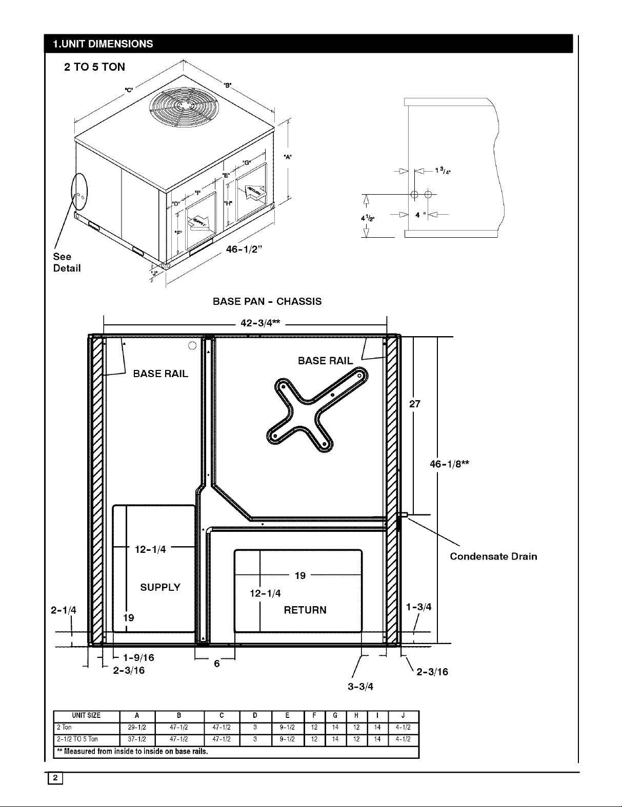
2 TO 5 TON
See
Detail
41/2"
BASE PAN - CHASSIS
42-3/4"*
BASE RAIL
27
46-1 !8"*
--" 12-1/4 i
Condensate Drain
19
SUPPLY 12-1/4
19
I
t
RETURN
1-9/16
2-3/16
3-3/4
1-3/4
/
I
2-3/16
UNITSIZE A B C D
2 Ton 29-1/2 47-1/2 47-1/2 3
2-1/2 TO 5Ton 37-1/2 47-1/2 47-1/2 3
** Measured from inside to inside on base rails.
E F G H I J
9-1/2 12 14 12 14 4-1/2
9-1/2 12 14 12 14 4-1/2
Page 3
2. SAFE INSTALLATION REQUIREMENTS
FIRE AND ELECTRICAL SHOCK HAZARD
Failure to carefully read and follow all instructions in this
manual could result in furnace malfunction, personal
injury, death and/or property damage.
Installation or repairs made by unqualified persons can
result in hazards to you and others. Installation MUST
conform with local building codes or, in the absence of
local codes, with the National Electrical Code
NFPA70-2005 or in Canada and CSA C.22.1 - Canadian
Electrical Code Part 1.
The information containedin this manual isintendedfor
use by a qualifiedservice technician familiar with safety
procedures and equipped withthe propertools and test
instruments.
• Seal supply and return air ducts.
• Check to see that filters are installed correctly and are
the proper type an size.
NOTE: Itis the personal responsibility and obligation of the
customer to contact a qualified installer to ensure that the
installation is adequate and conforms to governing codes
and ordinances.
3. LOCATING THE UNIT
ACCESS PANELS
See NO TAG for a general view of unit and location of
access panels.
CLEARANCES
The location MUST allow for minimum clearances and
should not be adjacent to a patio or other area where the
unit's operating sound level might be objectionable. The
combustion air inlet openings MUST not be obstructed (see
NO TAG). In addition, local codes MUST be observed.
NOTE: Units with available filter racks (3-1/2 to 5ton), need
a 26" minimum clearance at side of unit for removal of
filters. See Minimum Clearances below if unit is going to be
placed near combustible construction or materials.
While minimum clearances are acceptable for safety
reasons, they may not allow adequate air circulation around
the unit for proper operation inthe cooling mode. Whenever
possible, it is desirable to allow additional clearance,
especially around the condenser inlet and discharge
openings.
Do NOT install the unit in a location that will permit
discharged air from the condenser to recirculate to the
condenser inlet.
UNIT DAMAGE HAZARD
Failure to follow this caution may result in shorten life
of unit components.
Do NOT operate unit in a corrosive atmosphere
containing chlorine, fluorine, or any other corrosive
chemicals.
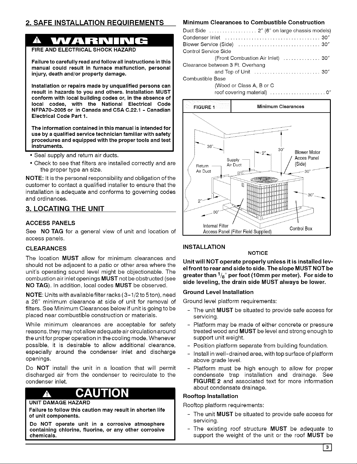
Minimum Clearances to Combustible Construction
Duct Side .................. 2" (6" on large chassis models)
Condenser Inlet .................................... 30"
Blower Service (Side) ............................... 30"
Control Service Side
(Front Combustion Air Inlet) .............. 30"
Clearance between 3 Ft. Overhang
and Top of Unit ......................... 30"
Combustible Base
(Wood or Class A, B or C
roof covering material) ..................... O"
FiGuRE i 1 Minimum Clearances
_ 36"_
3o" BlowerMotor
/ AeeesPanel
ASupPiYct I /(Side)
_ 30" _ _
InternalFilter
AccessPanel(FilterFieldSupplied)
INSTALLATION
NOTICE
Unit will NOT operate properly unless it is installed lev-
el front to rear and side to side. The slope MUST NOT be
greater than 1/8"per foot (10mm per meter). For side to
side leveling, the drain side MUST always be lower.
Ground Level Installation
Ground level platform requirements:
- The unit MUST be situated to provide safe access for
servicing.
- Platform may be made of either concrete or pressure
treated wood and MUST be level and strong enough to
support unit weight.
- Position platform separate from building foundation.
- Install in well-drained area, with top surface of platform
above grade level.
- Platform must be high enough to allow for proper
condensate trap installation and drainage. See
FIGURE 2 and associated text for more information
about condensate drainage.
Rooftop Installation
Rooftop platform requirements:
- The unit MUST be situated to provide safe access for
servicing.
- The existing roof structure MUST be adequate to
support the weight of the unit or the roof MUST be
Control Box
[]
Page 4
reinforced.
Check the weight of the unit in relation to the roof
structure and local building codes or ordinances and
reinforce roof structure if necessary.
- Support for the unit MUST be level and strong enough
to carry unit weight. The support may consist of a
platform or a combination of platform and roof beams or
curb.
HOISTING
NOTE: All access panels MUST be secured in place before
hoisting.
The unit should be hoisted with two lifting slings. Attach the
slings to rigging shackles that have been hooked through
holes in the base rail.
Two spreader bars MUST be placed on top of the unit to
protect the unit from damage from the pressure exerted by
the slings. Make sure that all equipment is adequate to
handle the weight ofthe unit and that the slings will not allow
the unit to shift.
Refer to Figure 8 for illustrated rigging instructions and
weight chart.
DOWNFLOW CONVERSION
NOTE: In downflow applications with roof curbs or jack
stands, the center rail under the unit must be removed. The
center rail is attached to the base rail with screws.
These units are adaptable to downflow use. To convert to
downflow use, follow these steps:
1. Remove the blockoff plates found in the return air
compartment and the supply air compartment.
NOTE: Blockoff plate in the supply air compartment only
contains one screw. If reinstalling plate, back part of plate
MUST fit into mating dimples on flange. To reinstall, slant
plate into dimples, then put plate into position and fasten
with screw.
2. Install the removed plates on the horizontal return and
supply air openings.
3. Install roof curb on the building. Be sure to follow all
directions included with curb and all applicable building
codes in your installation.
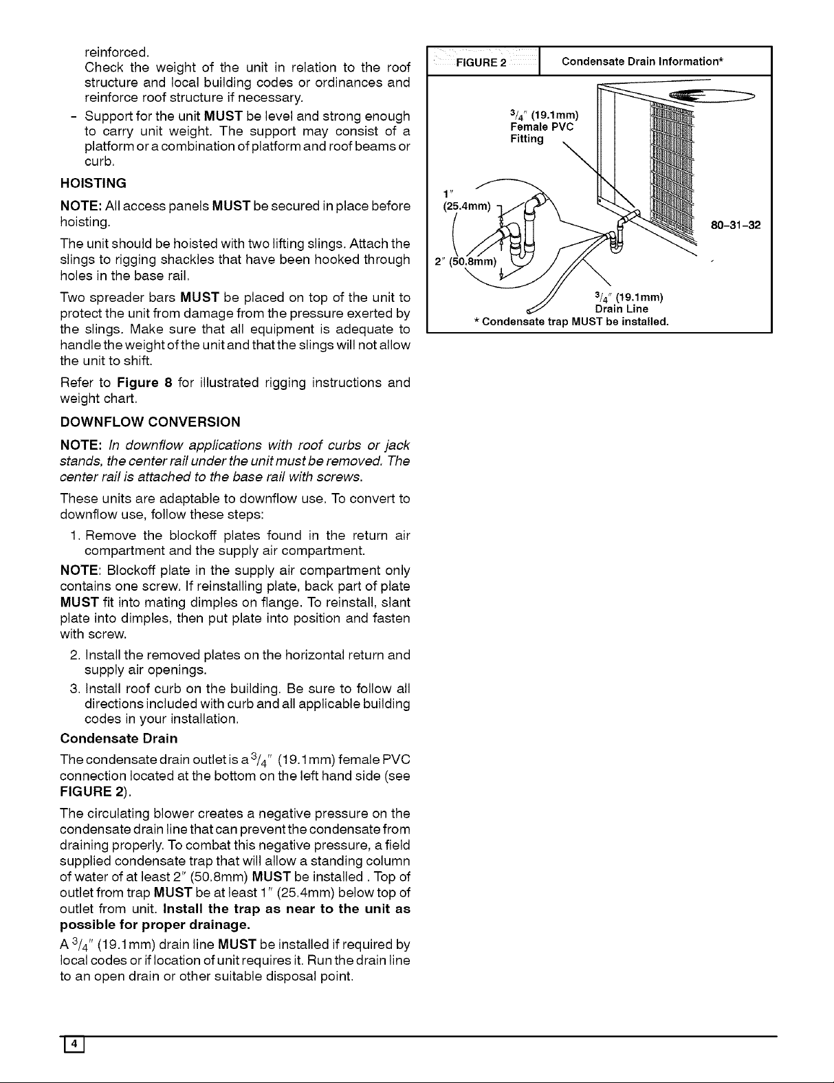
Condensate Drain
The condensate drain outlet is a 3/4" (19.1 mm) female PVC
connection located at the bottom on the left hand side (see
FIGURE 2).
The circulating blower creates a negative pressure on the
condensate drain line that can prevent the condensate from
draining properly. To combat this negative pressure, a field
supplied condensate trap that will allow a standing column
of water of at least 2" (50.8mm) MUST be installed. Top of
outlet from trap MUST be at least 1" (25.4mm) below top of
outlet from unit. Install the trap as near to the unit as
possible for proper drainage,
A 3/4" (19.1mm) drain line MUST be installed if required by
local codes or if location of unit requires it. Run the drain line
to an open drain or other suitable disposal point.
FIGURE 2 1 Condensate Drain Information*
3/4" (19.1mm)
Female PVC
Fitting _
(25.4mm)
(
2" (50.Smm)
3/4" (19,1mm)
Drain Line
* Condensate trap MUST be installed.
80-31-32
141
Page 5

4. ELECTRICAL WIRING
ELECTRICAL SHOCK HAZARD.
Failure to follow this warning could result in personal
injury, death and/or property damage.
The unit cabinet must have an uninterrupted,
unbroken electrical ground to minimize the possibility
of serious injury if an electrical fault should occur.
This ground may consist of an electrical wire
connected to the unit ground lug in the control
compartment, or conduit approved for electrical
ground when installed in accordance with National
Electric Code (NEC) NFPA 70, National Fuel Gas Code
NFPA 54-2005/ANSI Z223.1-2005 and local electrical
codes. In Canada, follow Canadian Electrical Code
CSA (Canadian Standards Association) C22.1 and
local electrical codes.
REDUCED EQUIPMENT LIFE HAZARD
Failure to follow these precautions could result in
damage to the unit being installed.
1)Make all electricalconnections inaccordance with
NationalElectriccode (NEC)NFPa70 andlocalelectrical
codes governing such wiring. In Canada, all electrical
connections must be inaccordance with CSA standard
C22.1, Canadian Electrical Code Part 1, and applicable
local codes. Refer to unit wiring diagram.
2) Use only copper conductor for connections
betweenfield-supplied electricaldisconnect switch and
unit. DO NOT USEALUMINUM WIRE.
3) Be sure that high-voltage power to unit is within
operating voltage range indicated on unit rating plate.
4) Donot damageinternalcomponentswhendrilling
through any panel to mount electrical hardware,
conduit, etc. Consult local power company for
correction of improper voltage and/orphase imbalance.
Disconnect Switch
The unit must have separate electrical service with a
field-supplied, waterproof, disconnect switch mounted at,
orwithin sight from, the unit. Refer tothe unit rating plate for
maximum fuse/circuit breaker size and minimum circuit
amps (ampacity) for wire sizing.
Ground Connections
Do NOT complete line voltage connections until unit is
permanently grounded. All line voltage connections and the
ground connection MUST be made with copper wire.
A ground lug is installed in the control box area for the
ground connection. Use a copper conductor of the
appropriate size from the unit to a grounded connection in
the electrical service panel or a properly driven and
electrically grounded ground rod. See warning above.
Line Voltage Wiring - (Wiring Diagrams page 12 & 13)
Connections for line voltage are made in the unit control box
area. Refer to wiring diagram located on the Burner Access
panel. For access, remove the burner access panel.
1. Run the high voltage (L1, L2) and ground leads into the
control box.
2. Connect ground lead to chassis ground connection.
3. Connect L1 to pressure lug connection 11 of the
compressor contactor.
4. Connect L2 to pressure lug connection 23 of the
compressor contactor.
Thermostat / Low Voltage Wiring
Location of the thermostat has an important effect on home
comfort. FOLLOW THE THERMOSTAT INSTRUCTION
MANUAL FOR CORRECT LOCATION, MOUNTING, AND
WIRING.
For 2 to 3-1/2 Ton Models Only:
A single stage thermostat is required for proper operation.
Thermostat must have the following terminals: "R', "W',
"Y", and "G'. Some electronic thermostats use low voltage
from the unit for power for temperature display and
programming. These electronic thermostats will have a'C"
terminal. The outdoor unit has color-coded wires for easy
connection. Using wire nuts, follow FIGURE 3 for proper
connections:
FIGURE 3 2 to 3-1/2 Ton Thermostat Connections
_!_ REO
\ J
K J i ',
Thermostat and subbase Unit Control Power
For 4 to 5 Ton Models Only:
A two-stage thermostat is required for proper operation.
Thermostat should have the following terminals: "R",
"W/W1 ", "Y1", "Y2", and "G'. Some electronic thermostats
use low voltage from the unit for power for temperature
display and programming. These electronic thermostats
will have a "C" terminal. The outdoor unit has color-coded
wires for easy connection. Using wire nuts, follow FIGURE
4 for proper connections:
FIGURE 4 4 to 5 Ton Thermostat Connections
©
Cv
©
Thermostat and subbase Unit Control Power
Page 6

THERMOSTAT HEAT ANTICIPATOR
Some thermostats have an adjustable heat anticipator. The
heat anticipator prevents temperature overshoot in heating
mode. If the heat doesn't turn off until the set point
temperature on the thermostat is exceeded, then the
anticipator setting is too low. If the heat turns off before the
thermostat reaches the set point temperature on the
thermostat, then the anticipator setting is too high. Follow
the thermostat instruction manual for proper adjustment of
the heat anticipator.
Final Electrical Check
1. Make a final wiring check to be sure system is correctly
wired. Inspect field installed wiring and the routing to
ensure that rubbing or chafing due to vibration will not
occur.
NOTE: Wiring MUST be installed so it is protected from
possible mechanical damage.
5. DUCTWORK
Ductwork Sizing
The maximum recommended velocity in trunk ducts is 1000
feet per minute. The maximum recommended velocity in
branch ducts is 800 feet per minute.
Ductwork sizing affects the discharge temperature, airflow
velocity, and efficiency of the system. Be sure to properly
size ductwork to the capacity of the unit and to the airflow
requirements of the conditioned space. Failure to properly
size ductwork can result in inadequate airflow and poor
efficiency. Undersized ductwork may result in tripped limit
controls and premature failure of compressors, motors and
other components.
Ductwork Insulation
Ductwork installed outdoors must have a minimum 2" thick
fiberglass "wrap" insulation and a weatherproof vapor
FIGURE 5 Filter Sizes
barrier installed around it. The insulation and vapor barrier
must be protected against potential damage. Caulking,
flashing, and other means of providing a permanent
weather seal must be used.
Ductwork Connections
The use of flexible, non-combustible connectors between
main trunk ducts and supply and return air plenums is
permitted. If flexible connectors are used, they should be
protected from potential mechanical damage such as
punctures and tears.
NOTE: When connecting the supply and return plenums to
the unit, make sure that the plenums are sealed against the
side casing of the unit and do not interfere with removal of
the top of the unit.
FILTERS
All return air MUST pass through a filter before entering the
unit. An electronic air cleaner, optional filter racks, or other
accessible filter arrangement must be installed in the return
air ductwork. Minimum recommended filter sizes are listed
in FIGURE 5 and are based on maximum face velocities of
300 ft/min for disposable filters and 500 ft/min for washable
(high velocity) filters. See FIGURE 5 for filter sizes.
REDUCED EQUIPMENT LIFE HAZARD
Failure to follow this caution may result in improper
unit operation.
Do not operate the unit without a filter,
PAF3 Filter sizes
Model
PAF324000K00A1
PAF330000K00A1
PAF336000K00A1
PAF342000K00A1
PAF348000K00A1
PAF354000K00A1
Disposable Filters
Nominal Size
(Qty x w x d)
1 x 20" x 20"
1 x 20" x 24"
2x 15"x20"
2x 18"x20"
2 x20"x20"
2 x20"x24"
Minimum Area
(sq inches)
384
480
576
672
768
900
Wasable Filters
Nominal Size
(Qty x w x d)
1 x 12" x 20"
1 x 15" x 20"
1 x 18" x 20"
1 x 20" x 20"
1 x 20" x 24"
1 x 24" x 24"
Minimum Area
(sq inches)
231
288
346
4O4
461
54O
Page 7

6. AIRFLOW ADJUSTMENT
CIRCULATING AIR BLOWER SPEEDS
BLOWERPERFORMANCEDATA
ModeINumber PAF324000KOOA1 PAF330000K00A1 PAF336000K00AI PAF342000K00AI PAF348000K00AI PAF354000KOOA1
SpeedTap 1 2 3 4 1 2 3 4 1 2 3 4 t 2 3 4 t 2 3 4 t 2 3 4
0.1 891 1136 986 1076 1286 1352 1162 1278 1529 1652 1138 1240 1505 1643 1154 1245 1750 1908 1348 1449 1998 2173
0.2 845 1098 949 1038 1225 1311 1118 1233 1484 1607 1087 1189 1467 1609 1084 1170 1696 1864 1274 1372 1943 2113
0.3 804 1056 908 997 1186 1274 1062 1191 1440 1574 1041 1145 1431 1577 1005 1110 1643 1819 1218 1318 1895 2067
AirDeliveryinCFM 0.4 758 1020 856 973 1158 1233 1014 1149 1402 1541 989 1104 1398 1541 940 1034 1592 1770 1151 1258 1850 2032
@Varying External 0.5 707 980 8t9 913 1129 1203 958 1108 1364 1501 940 1063 1363 1509 880 972 1547 1720 1085 1195 1800 2003
Static Pressure (in. 0.6 649 920 781 875 1085 1162 892 1060 1326 1462 865 1010 1324 1476 832 924 1497 1678 1032 1130 1750 1962
w.c.) 0.7 582 785 717 840 1044 1119 826 1005 1284 1426 806 952 1283 1439 780 875 1443 1632 989 1086 1705 1904
0.8 509 569 664 786 1004 1066 780 943 1238 1384 752 891 1234 1402 713 836 1400 1586 954 1048 1659 1822
0.9 318 612 717 948 989 735 892 1179 1338 694 828 1175 1352 663 773 1354 1538 904 1000 1602 1727
1 554 659 755 774 675 844 1123 1277 646 773 1120 1264 613 720 1302 1494 85I 946 1530 1603
Notes:
Air Defivery@listed external staticpressreare taken at 230Volts with Dry coil, no filter and approved heater
Forwet coit add .05 in. wc to Static Pressuremeasurement Note for 208Volts applications, reduceairflow by 15%
FIGURE 6
Blower Tap Connections
Blower Speed Tap Settings
Rated Airflow High Airflow
PAF324000K Speed Tap 1 Speed Tap 3
PAF330000K Speed Tap 2 Speed Tap 3
PAF336000K Speed Tap 2 Speed Tap 3
PAF342000K Speed Tap 3 Speed Tap 4
PAF348000K Speed Tap 3 (Hi); 2 (Lo) Speed Tap 4 (Hi); 3 (Lo)
PAF354000K Speed Tap 3 (Hi); 2 (Lo) Speed Tap 4 (Hi); 3 (Lo)
Verify that the proper blower speeds for heating and cooling
are selected on the blower motor by removing the blower
access panel and inspecting the blower motor, The motor
has 4 speeds numbered "1", "2", "3", and "4", The wires for
CONTINUOUS FAN OPERATION
Continuous fan speed operates at the cooling speed for 2
thru3-1/2 ton models and at the low stage cooling speed for
4 and 5 ton models.
the speed selection are as follows:
Red _ Heating
Black _ High Stage Cooling
Violet _ Low Stage Cooling (4 & 5 ton only)
Using the same speed for Heating and Cooling.
COOLING
1. Turn electric power OFF
2. Set thermostat Heat-Cool select to COOL.
3. Adjust thermostat setting to below room temperature.
4. Turn power ON, for approximately one minute, then
If the same speed is required for heating and high stage
cooling the following procedure must be used:
1. Set Red wire on proper speed selection on blower
motor.
2. Remove Black wire from "COOL" (2 - 3.5 Ton models)
or "HI" (4 - 5 Ton Models) on Blower Interface Board.
Tape end of Black lead using electrical tape.
3. Jumper the Red wire to both the "Heat" terminal and
either the "COOL" (2 - 3.5 Ton models) or'HI" (4 - 5Ton
Models) terminal on the Blower Interface Board.
If the same speed is required for heating and low stage
cooling (4 & 5 Ton models only), the following procedure
must be used:
OFF. During power application check the following:
a. Contactor - Contacts Closing
b. Compressor - ON
c. Condenser fan motor - ON
d. Circulating Air Blower - ON 0 second delay
5. Turn power OFE check the following:
a. Contactor contacts opening.
b. Compressor - OFF
c. Condenser fan motor - OFF
d. Circulating blower - OFF after a 60 second delay for
2 thru 3-1/2 ton models and a 90 second delay for 4
and 5 ton models.
1. Set Red wire on proper speed selection on blower
motor.
2. Remove Violet wire from "LO" on Blower Interface
Board. Tape end of Violet lead using electrical tape.
3. Jumper the Red wire to both the "Heat" terminal and the
"LO" terminal on the Blower Interface Board.
171
Page 8

7. START-UP PROCEDURES
CHECK BEFORE STARTING
1. Check that the blower motor speed terminal block is
running the correct heating and cooling speeds.
2. Check to see that clean, properly sized air filters are
installed.
3. Replace all service access panels.
Check the unit's operation as outlined in the following
instructions. If any unusual sparking, odors or unusual
noises are encountered, shut off electric power
immediately. Recheck for wiring errors, or obstructions in or
near blower motors.
1. Set thermostat Heat-Cool selector to OFE
2. Set thermostat fan switch to AUTO.
3. Turn electric power ON. Nothing should start running.
4. Set thermostat fan switch to ON,
5. Reset thermostat fan switch to AUTO,
8. Sequence of OPERATION
operation. When heating demand is met, W3 and W2
sequentially de-energize shutting the indoor fan and the
electric heater.
Heating Operation (048 - 054):
With a call for heating (W2), the auxiliary electric heater is
energized along with the Indoor blower. Ifthe demand is not
met, W3 is energized incase of staged heating. When
heating demand is satisfied, W3 and W2 sequentially
de-energize along with the indoor fan blower.
Continuous Fan:
With the continuous Indoor fan option selected on the
thermostat, G is continuously energized. Incase of 024 -
042 units, the selected airflow setting is provided. In the
case of 048 and 060 units, the system runs low stage (Y1)
airflow for continuous fan operation.
9. MAINTENANCE
MONTHLY MAINTENANCE AND INSPECTION
CHECKS
Air Filters
ELECTRICAL SHOCK HAZARD.
Failure to follow this warning could result in personal
injury, death and/or property damage.
Turn off electric power supply at disconnect switch or
service panel before removing any access or service
panel from unit.
Cooling Operation (024 - 042):
With a call for cooling (Y), the indoor fan energizes
immediately whereas the contactor energizes after a 5
minute time delay (incase of an initial start up) starting the
compressor and the outdoor fan motor. When the cooling
demand is met, (Y) de-energizes, shutting the compressor,
indoor fan and the outdoor fan.
Cooling Operation (048 - 054):
These units utilize a 2 stage indoor thermostat. With a first
stage call for cooling (Y1), the indoor fan (low stage)
energizes immediately whereas the contactor energizes
after a 5 minute time delay (incase of an initial start up)
starting the compressor (low stage) and the outdoor fan
motor. If the low stage operation cannot satisfy the cooling
demand, the second stage cooling (Y2) energizes
switching the compressor into high stage cooling through
energizing an internal solenoid valve inside the scroll
compressor and switching the indoor fan into high stage.
When second stage cooling is satisfied, Y2 de-energizes
switching the compressor and the indoor fan into low stage
cooling. When the low stage cooling demand is met, Y1
de-energizes shutting the compressor, indoor fan and the
outdoor fan.
Heating Operation (024 - 042):
With a call for heating (W2), the auxiliary or electric heat
energizes along with the Indoor blower. Incase of staged
heating, W3 is energized if the demand is not met. The
highest airflow selected is run while the electric heat is in
REDUCED EQUIPMENT LIFE HAZARD
Failure to follow this cautions may result in damage to
the unit being installed.
Do not operate the unit without a filter.
Inspect filters at least monthly and replace or clean as
required. Washable filters may be cleaned by soaking in
mild detergent and rinsing with cold water. Replace filters
with the arrows on the side pointing in the direction of air
flow. Dirty filters are the most common cause of inadequate
heating or cooling performance, and of compressor
failures.
COOLING SEASON CHECKS (MONTHLY)
Condenser Coil
Keep the condenser inlet and outlet area clean and free of
leaves, grass clippings or other debris. Grass should be
kept short in front of the condenser inlet. Shrubbery MUST
be trimmed back so it is no closer than 30 inches to unit.
Condensate Drain
Check for condensate drainage. Clean as required.
Page 9
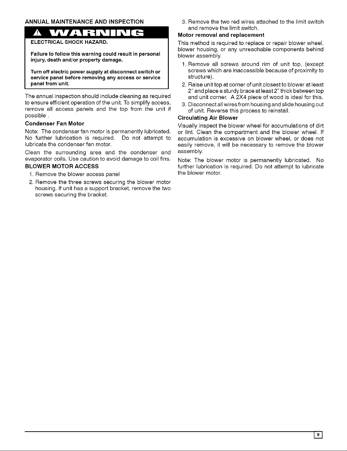
ANNUAL MAINTENANCEANDINSPECTION
ELECTRICAL SHOCK HAZARD.
Failure to follow this warning could result in personal
injury, death and/or property damage.
Turn off electric power supply at disconnect switch or
service panel before removing any access or service
panel from unit.
The annual inspection should include cleaning as required
to ensure efficient operation of the unit. To simplify access,
remove all access panels and the top from the unit if
possible.
Condenser Fan Motor
Note: The condenser fan motor is permanently lubricated.
No further lubrication is required. Do not attempt to
lubricate the condenser fan motor.
Clean the surrounding area and the condenser and
evaporator coils. Use caution to avoid damage to coil fins.
BLOWER MOTOR ACCESS
1. Remove the blower access panel
2. Remove the three screws securing the blower motor
housing. If unit has a support bracket, remove the two
screws securing the bracket.
3. Remove the two red wires attached to the limit switch
and remove the limit switch.
Motor removal and replacement
This method is required to replace or repair blower wheel,
blower housing, or any unreachable components behind
blower assembly.
1. Remove all screws around rim of unit top, (except
screws which are inaccessible because of proximity to
structure).
2. Raise unit top at corner of unit closest to blower at least
2" and place a sturdy brace at least 2" thick between top
and unit corner. A 2X4 piece of wood is ideal for this.
3. Disconnect all wires from housing and slide housing out
of unit. Reverse this process to reinstall.
Circulating Air Blower
Visually inspect the blower wheel for accumulations of dirt
or lint. Clean the compartment and the blower wheel. If
accumulation is excessive on blower wheel, or does not
easily remove, it will be necessary to remove the blower
assembly.
Note: The blower motor is permanently lubricated. No
further lubrication is required. Do not attempt to lubricate
the blower motor.
191
Page 10
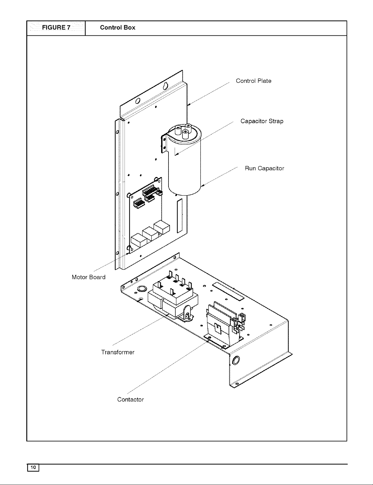
FIGURE 7
Control Box
Control Plate
Capacitor Strap
j-
.j/ Run Capacitor
Motor Board
Transformer
Page 11

R GG NG INSTRUCTIONS __
fAiLURETOfOLLOW-_-SE_.STRUC-r_O_S
//_ WA_\ NO CAN RESULT IN PROPERTY DAMAGE,
BoD,_,_u_R_oRDEAT_
.o
:D
C:
rn
QO
- ALL PANELS MUST BE IN PLACE WHEN RIGGING AND LIFTING.
- HOOK RIGGING SHACKLES THROUGH HOLES IN BASE RAIL, AS SHOWN IN DETAIL-A.
- USE SPREADER BARS, WHEN RIGGING, TO PREVENT UNIT DAMAGE.
- BE SURE RIGGING AND SHACKLES ARE SUFFICIENT TO HANDLE WEIGHT LISTED BELOW.
DETAIL-A
DER BARS
-¢
HEIGHT
_OR _
_J
LENGTH WIDTH
tQ
t_
f-
0
m.
o
:3
F
Max. Length Max. Width
Cabinet IN MM IN MM
2Ton 48 1219 48 1219
2-1/2 to 5 Ton 48 1219 48 1219
Max. Height
IN MM
30 762
38 965
Max. Weight
LB KG
300 137
400 182
Page 12
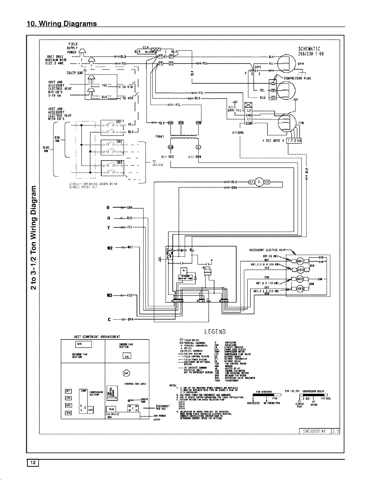
10. Wiring Diagrams
Fl_t 0
f_
,n
,m
C_l
cO
C_l
E
Ol
li
O_
ol
O'i
li
0
_ _I_! ¸ K_L
O _N_ 7
m
!
ii
II ? I :_.......
II | l ] II _,,,,,a,,,i__
!! !_ ; .... ]........ , .l{t%_ l{,l
UNIT CO_ON_NT _kNC_E_EXT
I i
®
Ill lll,ltt _lil_l_ll_ Illtl
Ifllll
{ 5_}6 589i_8 !3 0
Page 13

[I[L_
SCHEN_ATIC
2081230-140
E
r-
"r"
r-
t_
O
BL_
+
m2
Y2
_'I II},_I_ KII_ _B_ -II¸_
C _BkN
LEGEND
BNIT {OHPC_4[NT k_L!_6_WE_T
®
_L
EXCEPT
 Loading...