

Page 1
• Safety Labeling & Rules
• Installation Requirements
• Location / Clearances
',× _ ,
• Air Distribution
• Wiring '_
• Ductwork Connections
• Economizer Accessory
• Start-Up
• Maintenance
• Hoisting / Rigging
MODELS
PAB240 RAMA20
513 01 14 01 01 7/1/97
LP1
Page 2
Table of Contents
1. Safety Labeling and Signal Words ........................... 2
Danger, Warning and Caution
...............................................................
Signal Words
...............................................................
Signal Words in Manuals ............................................. 2
Product Labeling ................................................... 2
Danger Label ...................................................... 2
Warning Label ..................................................... 2
Caution Label ...................................................... 2
2. Unit Dimensions ......................................... 3
3. Safe Installation Requirements ............................. 4
4. Location And Set-up ..................................... 5
Access Panels ...................................................... 5
Clearances ......................................................... 5
Minimum Clearances to Combustible and
non-Combustible Construction (Horizontal Flow) ................... 6
Minimum Clearances to Combustible and
non-Combustible Construction (Downflow) ........................ 6
Installation ........................................................ 7
Ground Level Installation ............................................ 7
Rooftop Installation ................................................. 7
Hoisting ........................................................... 7
Converting to Horizontal Operation ................................... 7
Condensate Drain .................................................. 7
5. Electrical Wiring ......................................... 9
Line Voltage Wiring ................................................. 9
Line Connections ................................................... 9
Converting 230V Units to 208V ....................................... 9
Field Installed Equipment ........................................... 10
Low Voltage Wiring ................................................. 10
Low Voltage Wiring With Economizer Option ........................... 10
Thermostat ........................................................ 10
Heat Anticipator ................................................... 10
Final Check ........................................................ 10
6. Air Distribution System ................................... 11
Ductwork .......................................................... 11
Ductwork Connections .............................................. 11
Filters ............................................................ 11
Circulating Blower ................................................. 11
Determining Blower Speed ........................................... 11
7. Adjustable Belt Drive Blower ............................... 14
8. Economizer Accessory ..................................... 16
Static Additions .................................................... 16
Page 3
Theory of Operation ................................................ 16
Sequence of Operation .............................................. 17
9. Start-up Procedure ...................................... 18
Blower and Phasing Check ........................................... 18
Cooling Checks ..................................................... 19
10. Operation And Maintenance Instructions ................... 20
Turning Off the Unit ................................................ 20
Heating ........................................................... 20
Cooling ........................................................... 20
Starting the Unit After Shutdown ..................................... 20
Heating ........................................................... 20
Cooling ........................................................... 20
Thermostat Fan Switch Operation ..................................... 20
Adjusting Room Temperatures ........................................ 20
Monthly Maintenance and Inspection Checks ........................... 21
Air Filters (Factory Installed) ......................................... 21
Disposable Replacement Filters ....................................... 21
Cooling Season Checks (Monthly) ..................................... 21
Condenser Coil ..................................................... 21
Condensate Drain .................................................. 21
Annual Maintenance and Inspection ................................... 21
Circulating Air Blower .............................................. 21
11. Rigging Instructions ..................................... 23
Page 4
I Single Package Air Conditioners Installation Instructions !
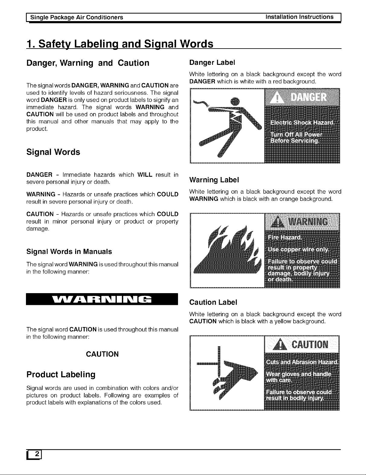
1. Safety Labeling and Signal Words
Danger, Warning and Caution
The signal wordsDANGER, WARNING and CAUTION are
used to identify levels of hazard seriousness. The signal
word DANGER is only used on product labels to signify an
immediate hazard. The signal words WARNING and
CAUTION will be used on product labels and throughout
this manual and other manuals that may apply to the
product.
Signal Words
DANGER - Immediate hazards which WILL result in
severe personal injury or death.
WARNING - Hazards or unsafe practices which COULD
result in severe personal injury or death.
CAUTION - Hazards or unsafe practices which COULD
result in minor personal injury or product or property
damage.
Danger Label
White lettering on a black background except the word
DANGER which is white with a red background.
Warning Label
White lettering on a black background except the word
WARNING which is black with an orange background.
Signal Words in Manuals
The signal word WARNING is used throughout this manual
in the following manner:
The signal word CAUTION is used throughout this manual
in the following manner:
CAUTION
Product Labeling
Signal words are used in combination with colors and/or
pictures on product labels. Following are examples of
product labels with explanations of the colors used.
Caution Label
White lettering on a black background except the word
CAUTION which is black with a yellow background.
12J
Page 5
_ Installation Instructions Single Package Air Conditioners I
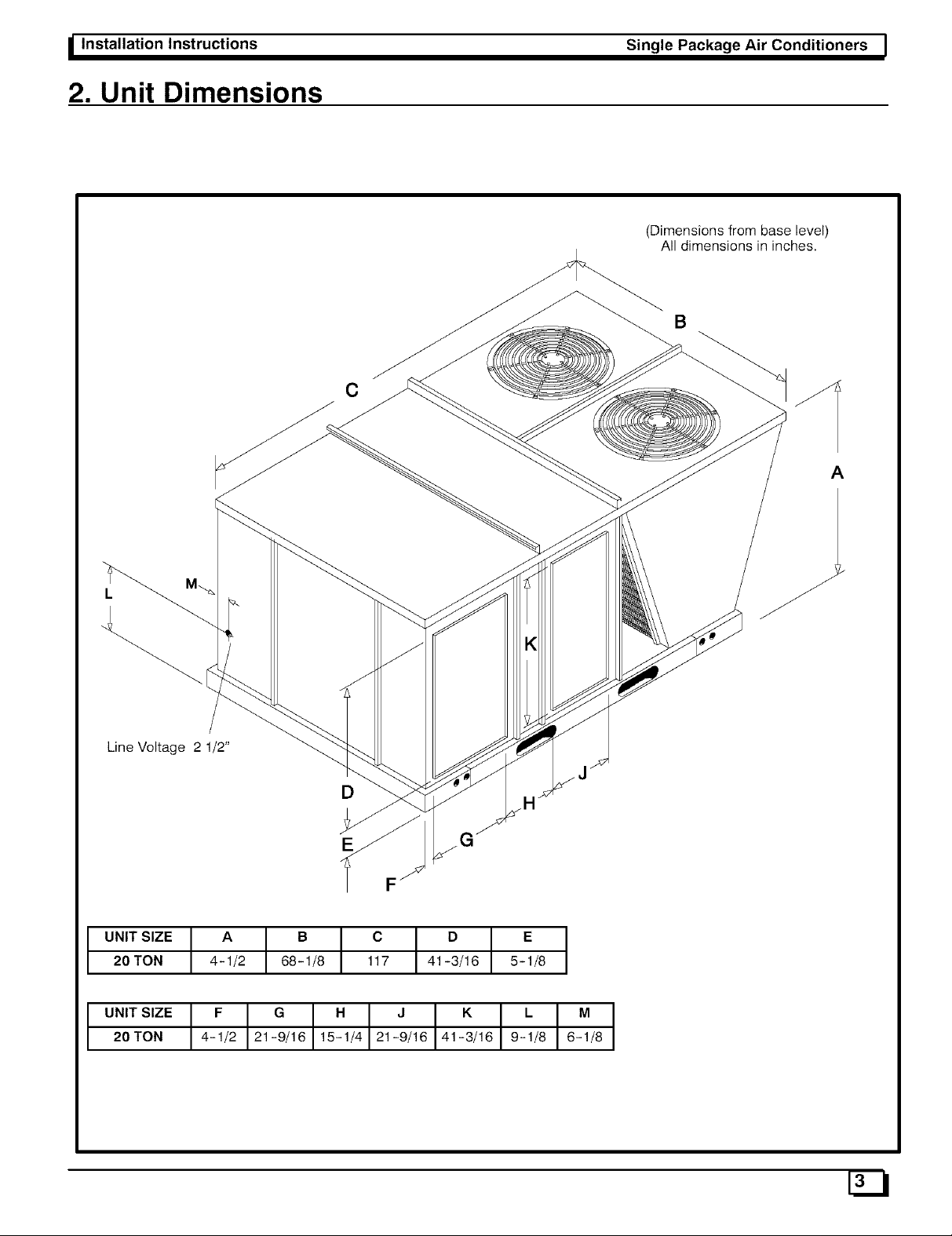
2. Unit Dimensions
(Dimensions from base level)
All dimensions in inches.
B
C
A
Line Voltage 2 1/2"
D
G
F
UNIT SIZE A B C / D E
20TON 4-1/2 68-1/8 117 T 41-3/16 5-1/8
U.,TS,Z.t_ o .
20 TON 21-9/16 21-9/16 41-3/16
Page 6
I Single Package Air Conditioners
3. Safe Installation Requirements
Installation or repairs made by unqualified
persons can result in hazards to you and others.
Installation must conform with local building
codes or, in the absence of local codes, with
National Electrical Code ANSI/NFPA 70-1990 or
current edition. In Canada the National Standard
CAN/CGA 1-B149.1 or current edition and CSA
C.22.1 - Canadian Electrical Code Part 1 or
current edition.
The information contained in this manual is
intended for use by aqualified service technician
familiar with safety procedures, equipped with
the proper tools and test instruments.
Failure to carefully read and follow all instruc-
tions in this manual can result in furnace
malfunction, property damage, personal injury
and/or death.
Installation Instructions
Installation MUST conform to the most current
version of the following standards or a superseding
standard.
In the United States:
• National Electrical Code ANSI/NFPA 70-1990
In Canada:
• CSA C.22.1 - Canadian Electrical Code Part 1.
Seal supply and return air ducts.
NOTE: It is the personal responsibility and obligation of the
customer to contact a qualified installer to ensure that the
installation is adequate and conforms to governing codes
and ordinances.
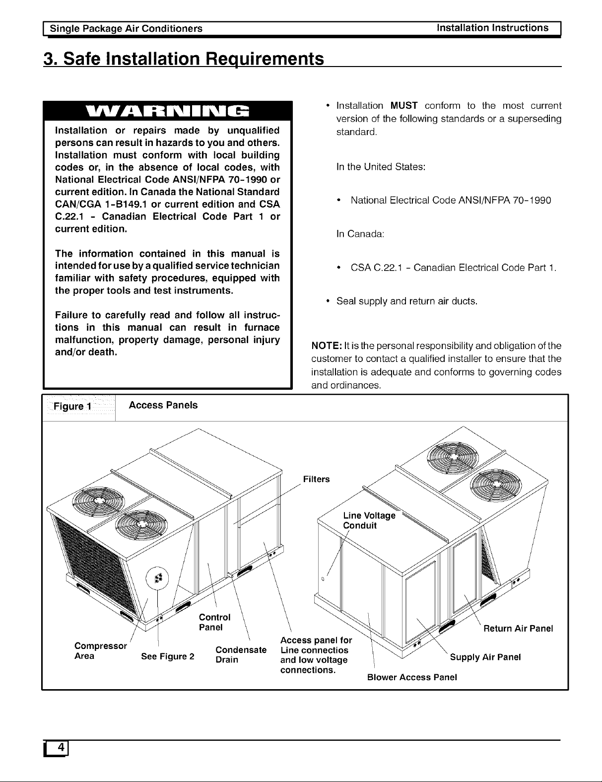
Figure ! 1 Access Panels
Control
Panel
Compressor Condensate
Area See Figure 2 Drain
Filters
Access panel for
Line connectios
and low voltage
connections.
Return Air Panel
Supply Air Panel
Blower Access Panel
Page 7
_ Installation Instructions Single Package Air Conditioners I
4. Location And Set-up
The unit is designed for outdoor installation ONLY. The unit
may be installed on a level concrete mounting base (or
other adequate platform) at ground level oron a flat rooftop
with an adequate platform. If using as a downflow model,
use a roof curb. Typical installations are shown in Figures
3 and 4.
Access Panels
CAUTION
Unit will NOT operate properly without all access
panels in place. Access panels are shown in Figure 1.
Unit MUST NOT be moved unless all access panels are
in place.
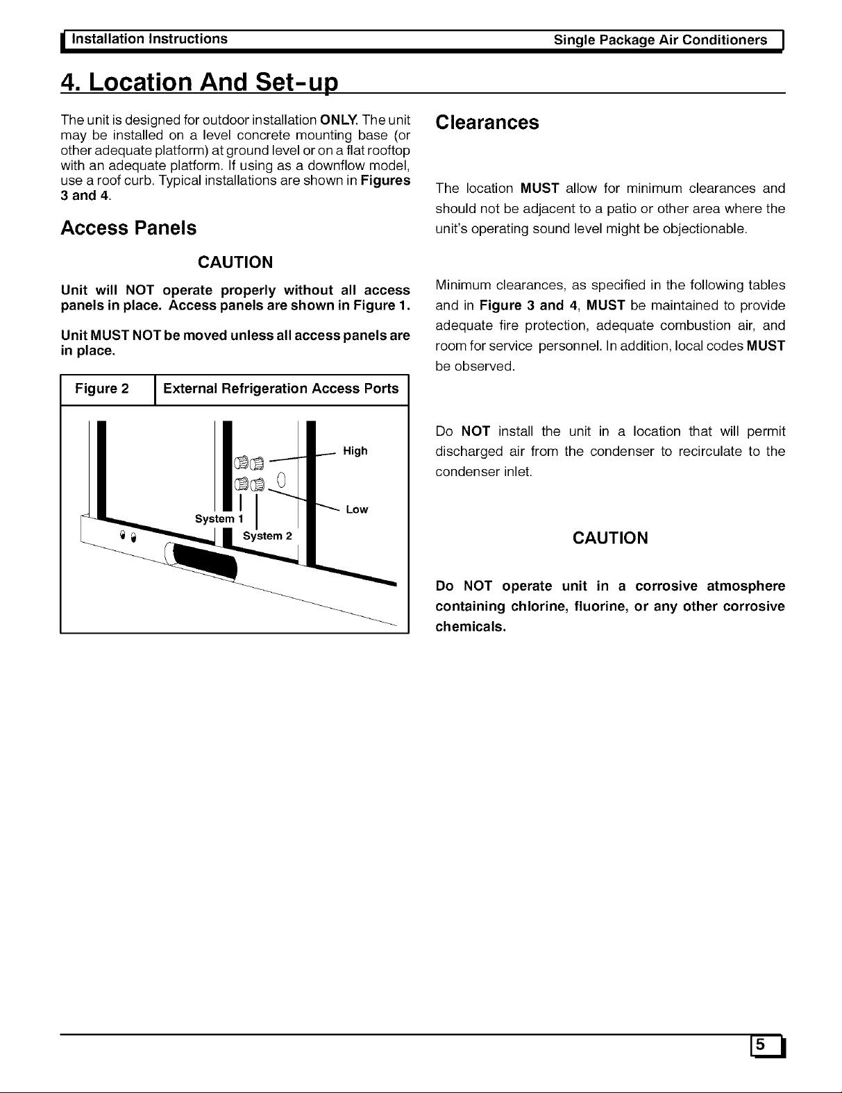
Figure 2 I External Refrigeration Access Ports
1
High
Low
System 1
_ System 2
Clearances
The location MUST allow for minimum clearances and
should not be adjacent to a patio or other area where the
unit's operating sound level might be objectionable.
Minimum clearances, as specified in the following tables
and in Figure 3 and 4, MUST be maintained to provide
adequate fire protection, adequate combustion air, and
room for service personnel. In addition, local codes MUST
be observed.
Do NOT install the unit in a location that will permit
discharged air from the condenser to recirculate to the
condenser inlet.
CAUTION
Do NOT operate unit in a corrosive atmosphere
containing chlorine, fluorine, or any other corrosive
chemicals.
Page 8
I Single Package Air Conditioners
Installation Instructions !
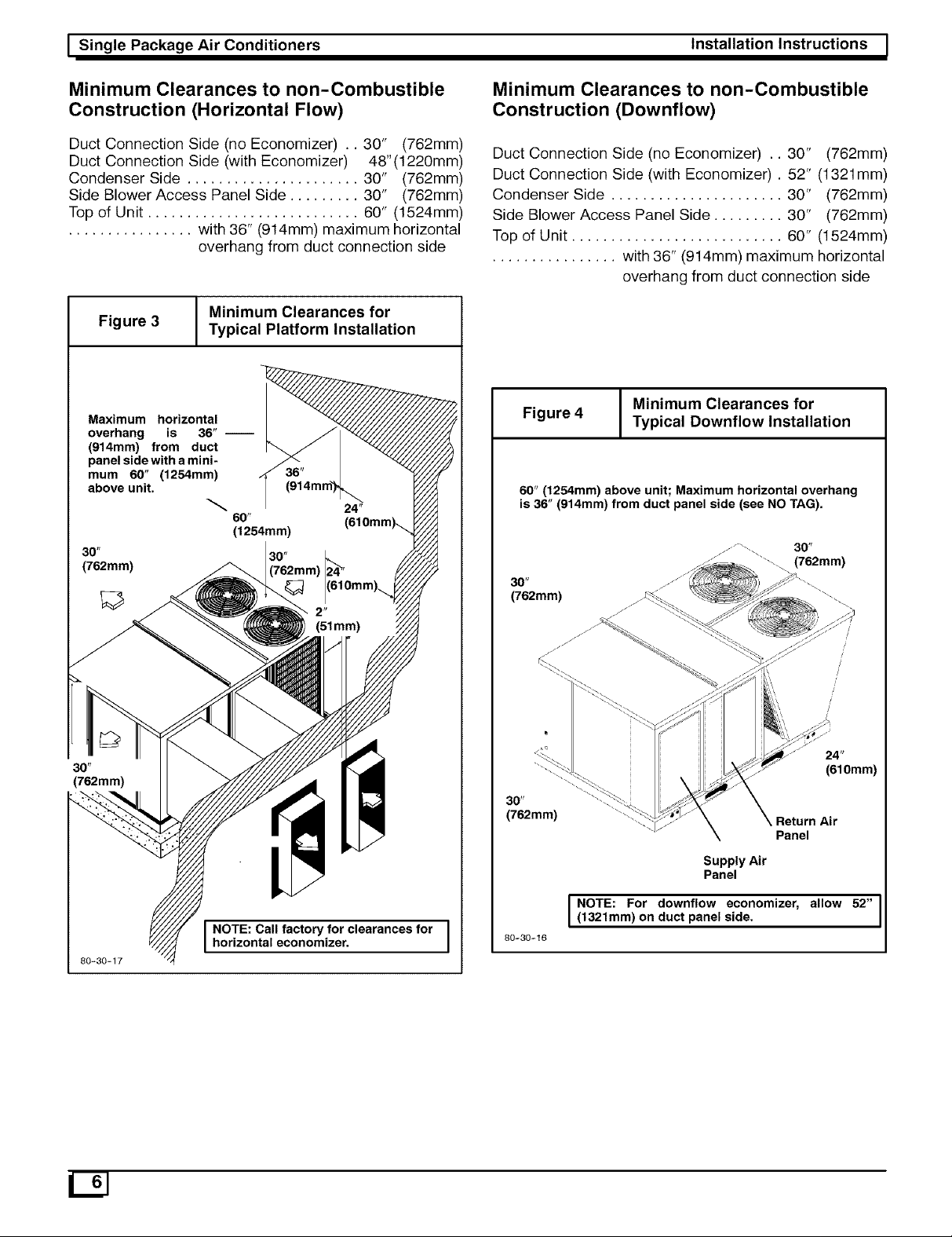
Minimum Clearances to non-Combustible
Construction (Horizontal Flow)
Duct Connection Side (no Economizer) .. 30" (762mm)
Duct Connection Side (with Economizer) 48"(1220mm)
Condenser Side ...................... 30" (762mm)
Side Blower Access Panel Side ......... 30" (762mm)
Top of Unit ........................... 60" (1524mm)
................ with 36" (914mm) maximum horizontal
overhang from duct connection side
Minimum Clearances for
Figure 3 Typical Platform Installation
Maximum horizontal
overhang is 36" i
(914mm) from duct
panel side with a mini-
mum 60" (1254mm)
above unit.
60"
Minimum Clearances to non-Combustible
Construction (Downflow)
Duct Connection Side (no Economizer) .. 30" (762mm)
Duct Connection Side (with Economizer) . 52" (1321mm)
Condenser Side ...................... 30" (762mm)
Side Blower Access Panel Side ......... 30" (762mm)
Top of Unit ........................... 60" (1524mm)
................ with 36" (914mm) maximum horizontal
overhang from duct connection side
Minimum Clearances for
Figure 4 Typical Downflow Installation
60" (1254mm) above unit; Maximum horizontal overhang
is 36" (914mm) from duct panel side (see NO TAG).
30 _
(762mm)
30 _
(762mm)
80-30-17
horizontal economizer.
I NOTE: Call factory for clearances for I
30"
(762mm)
30"
(762mm)
80-30-16
30 _
(762mm)
24"
(610mm)
Return Air
Panel
SupplyAir
Panel
I NOTE: For downflow economizer, allow 52"(1321mm) on duct panel side.
Page 9

_ Installation Instructions Single Package Air Conditioners I
Installation
CAUTION
Unit will NOT operate properly unless it is installed
level front to rear and side to side.
The slope MUST NOT be greater than 1/8" per foot
(10mm per meter). For side to side leveling, the control
box side MUST always be lower.
Ground Level Installation
Ground level platform requirements:
The unit MUST be situated to provide safe access for
servicing.
Platform may be made of either concrete or pressure
treated wood and MUST be level and strong enough
to support unit weight.
Position platform separate from building foundation.
Install in well-drained area, with top surface of
platform above grade level.
Platform MUST be high enough to allow for proper
condensate trap installation and drainage. See
Figure 5 and associated text for more information
about condensate drainage.
- See Hoisting section below for hoisting instructions.
NOTE: Cardboard covers on horizontal supply and
return duct openings MUST be removed before
starting unit.
Hoisting
NOTE: All access panels MUST be secured in place before
hoisting.
The unit should be hoisted with two lifting slings. Attach the
slings to rigging shackles that have been hooked through
holes in the base rail.
Two spreader bars MUST be placed on top of the unit to
protect the unit from damage from the pressure exerted by
the slings. Make sure that all equipment is adequate to
handle the weight of the unit and that the slings will not
allow the unit to shift.
Refer to the back cover of this manual for illustrated
rigging instructions and weight chart.
Converting to Horizontal Operation
These units are shipped ready for downflow operation but
are adaptable to horizontal use. To convert to horizontal
operation, follow these steps:
Rooftop Installation
Rooftop platform requirements:
The unit MUST be situated to provide safe access for
servicing.
The existing roof structure MUST be adequate to
support the weight of the unit or the roof MUST be
reinforced.
Check the weight of the unit in relation to the roof
structure and local building codes or ordinances and
reinforce roof structure if necessary. See the back
cover of this manual for unit weights and corner
weights.
Support for the unit MUST be level and strong
enough to carry unit weight. The support may consist
of a platform or a combination of platform and roof
beams or curb.
The platform may be constructed of pressure treated
wood and may be covered with Class A, B or C roof
covering.
Platform MUST allow for proper condensate trap
installation and drainage. See Figure 5 and
associated text for more information about
condensate drainage.
1.
Remove horizontal supply and return panels (see
Figure 1).
2.
Remove cardboard covers from downflow supply
and return openings.
.
Install horizontal supply and return panels on
downflow supply and return openings. Be sure
flanges are down and insulation side is up. Install
from inside of unit.
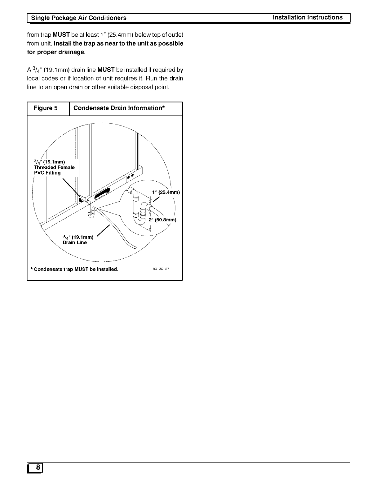
Condensate Drain
The condensate drain outlet is a 3/4" (19.1mm) threaded
female PVC connection located at the bottom of the unit to
the left of the electrical access panel (see Figure 5).
Condensate drain outlet MUST be held with wrench when
installing trap and drain line.
The circulating blower and the condenser fan create a
negative pressure on the condensate drain line that will
prevent the condensate from draining properly without a
trap. To combat this negative pressure, a field supplied
condensate trap that will allow a standing column of water
of at least 2" (50.8mm) MUST be installed. Top of outlet
Page 10
I Single Package Air Conditioners Installation Instructions !
from trap MUST be at least 1" (25.4mm) below top of outlet
from unit. Install the trap as near to the unit as possible
for proper drainage.
A3/4 " (19.1mm) drain line MUST be installed if required by
local codes or if location of unit requires it. Run the drain
line to an open drain or other suitable disposal point.
Figure 5 I Condensate Drain Information*
3/4" (19.1mm)
Threaded Female
PVC Fitting
1" (25.4mm)
/,
\
3/4"(19.1mm)
Drain Line
* Condensate trap MUST be installed.
2" (50.8mm)
8_3_27
Page 11

I Installation Instructions
5. Electrical Wiring
Electrical shock hazard.
Shut off electric power at unit disconnect or ser-
vice panel before making any electrical connec-
tions.
Unit MUST be grounded to electrical service pan-
el.
Failure to follow this warning can result in prop-
erty damage, personal injury, and/or death.
NOTE: All electrical work MUST conform with the
requirements of local codes and ordinances and in the
United States the National Electrical Code
ANSI/NFPA70-1990 (or current edition) and in Canada
CSA C.22.1 - Canadian Electrical Code Part 1 (or current
edition). Provide line voltage power supply from a separate
protected circuit with a disconnect switch (when required)
located within sight of the unit. Supply voltage, amperage,
wire, fuse and disconnect switch sizes MUST conform with
specifications on the unit rating plate.
Single Package Air Conditioners I
Figure 6 J Control Box
Anti-Cycle
Anti-Cycle Timer 1
Timer 2 _,
Transformer
Transformer (460/575 Volt
(240v) Only)
Contactor
DSP
(Blower)
Contactor
Contactor C2
Contactor C1
Ground Lug
Wiring MUST be protected from possible mechanical
damage and MUST NOT interfere with removal of access
panels, filters, etc.
All exposed wiring or connections MUST be made with
weatherproof cable or wire unless installed in conduit.
Connections for line voltage are made in the lower blower
section section. Low voltage connections are made at the
terminal board in the blower section on the right hand side
(see Figure 7).
For access to high and low voltage connections, remove
the lower blower access panel. (see Figure 1).
Line Voltage Wiring
Line voltage wires enter the unit through the double
knockout on the end of the unit next to the blower. (see
Figure 7). Do NOT complete line voltage connections until
unit is permanently grounded. All line voltage connections
and the ground connection MUST be made with copper
wire.
fans)
Line Connections
Complete the line service connections to the terminal block
in the blower section. Refer to applicable wiring diagram.
Check all screw terminals to ensure they are tight.
Converting 230V Units to 208V
To convert 230V units to 208V:
1. Turn electric power OFF.
2. Remove control box access panel and open control
box. Locate the 24V control transformer.
.
Remove wires from the terminal labeled '240V' on
the 24V control transformer and reconnect them to
the 208V terminal of the 24V control transformer.
4.
Close control box and replace control box access
panel.
Page 12
I Single Package Air Conditioners
Installation Instructions
Field Installed Equipment
All wiring done in the field between the unit and other
devices, or between separate devices that are field
installed and located, MUST not exceed the temperature
limitations for type T wire and MUST be installed according
to the manufacturer's instructions for the devices.
Low Voltage Wiring
Low voltage wiring connections for the thermostat are
made at the 24V terminal board which is located in the
lower blower section. For access, remove the lower blower
access panel. Refer to the wiring diagram and the
instructions included with the thermostat.
Low Voltage Wiring With Economizer
Option
The economizer electrical harness taps into Y1 and Y2 on
the low voltage terminal board. Low voltage wires from the
thermostat are connected to Y1 and Y2 with or without an
economizer.
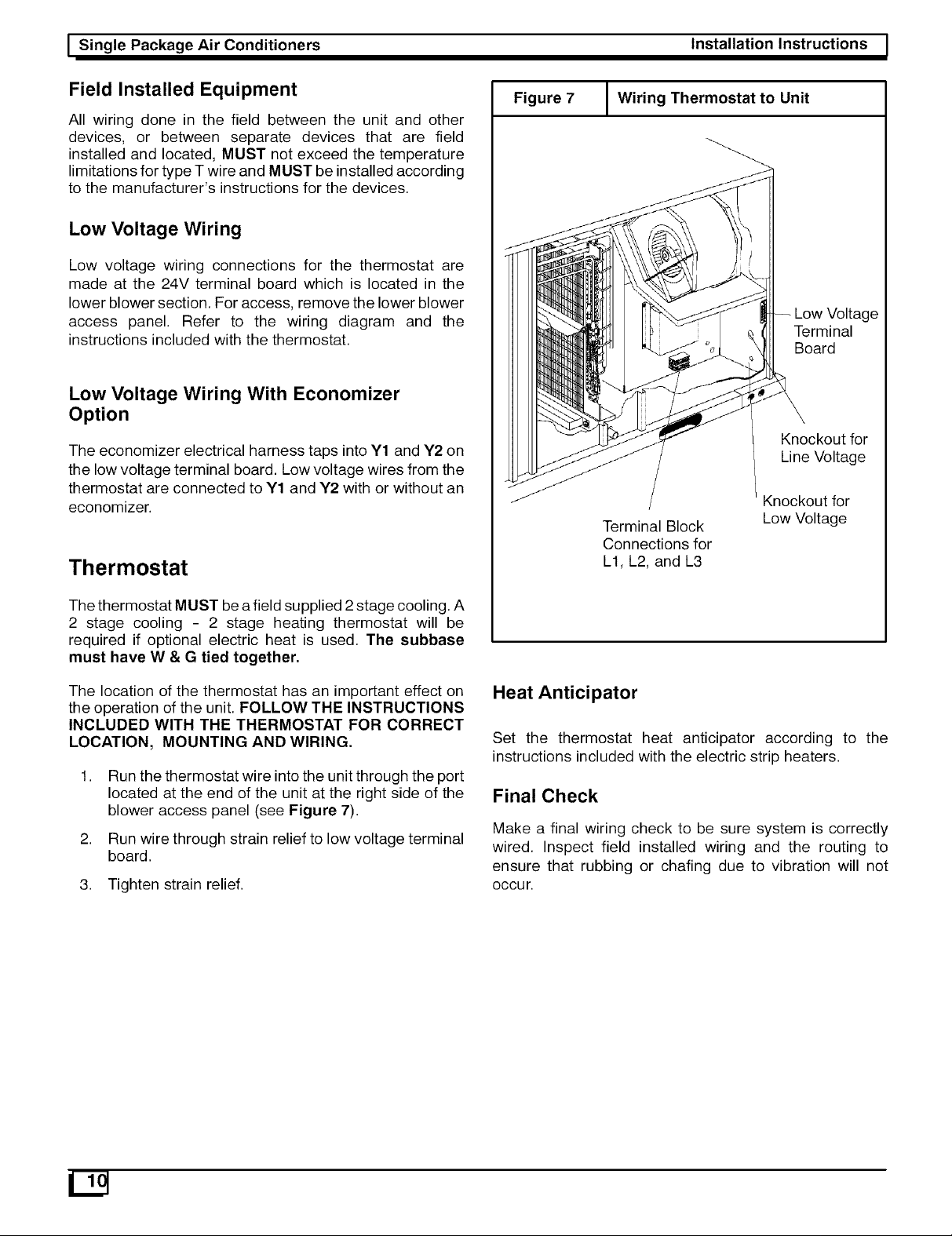
Thermostat
Figure 7
J Wiring Thermostat to Unit
Knockout for
Line Voltage
Knockout for
Terminal Block
Connections for
L1, L2, and L3
Low Voltage
Terminal
Board
The thermostat MUST be afield supplied 2stage cooling. A
2 stage cooling - 2 stage heating thermostat will be
required if optional electric heat is used. The subbase
must have W & G tied together.
The location of the thermostat has an important effect on
the operation of the unit. FOLLOW THE INSTRUCTIONS
INCLUDED WITH THE THERMOSTAT FOR CORRECT
LOCATION, MOUNTING AND WIRING,
1.
Run the thermostat wire into the unit through the port
located at the end of the unit at the right side of the
blower access panel (see Figure 7).
2.
Run wire through strain relief to low voltage terminal
board.
3. Tighten strain relief.
Heat Anticipator
Set the thermostat heat anticipator according to the
instructions included with the electric strip heaters.
Final Check
Make a final wiring check to be sure system is correctly
wired. Inspect field installed wiring and the routing to
ensure that rubbing or chafing due to vibration will not
Occur.
129
Page 13
_ Installation Instructions
6. Air Distribution System
Single Package Air Conditioners I
Ductwork
NOTE: The total heat loss from the structure as expressed
in total Btu/hr MUST be calculated by manufacturer's
method or in accordance with "A.S.H.R.A.E. Guide" or
"Manual N - Load Calculations" published by the Air
Conditioning Contractors of America or in Canada H.R.A.I.
"Manual N". The total heat loss calculated should be equal
to or less than the heating capacity.
Ductwork, supply registers, and return air grilles MUST be
designed and sized to handle the greater of the units
heating or cooling air volume requirements. If the unit is
connected to an existing system, the ductwork MUST be
checked to make sure it is adequate. Extra runs or larger
duct sizes may have to be installed. Use only
non-combustible type insulation on supply plenum or
supply ductwork within 6 feet of unit.
Maximum recommended velocity in trunk ducts is 1000
feet per minute (5.08 m/s). Velocity in branches should not
exceed 800 feet per minute (4.06 m/s).
Ductwork installed outdoors should have a minimum of 2"
(50.8mm) of fiberglass insulation and a weatherproof
vapor barrier. It should also be protected against damage.
Caulk and flashing, or other means adequate to provide a
permanent weather seal should be used.
Ductwork installed in attics or other areas exposed to
outside temperatures should be installed with a minimum
of 2" (50.8mm) fiberglass insulation and have an indoor
type vapor barrier.
Ductwork Connections
The use of flexible, non-combustible connectors
between main trunk ducts and supply and return air
plenums is recommended to minimize vibration
transmission.
NOTE: Connect supply and return air plenums to unit in a
manner that will allow the top of the unit to be removed
without removing plenums. Plenums MUST be individually
sealed to unit casing.
Filters
CAUTION
All air MUST pass through a filter before entering the unit.
Electronic air cleaner, optional filter racks, or other
accessible filter arrangements MUST be installed in the
return air ductwork.
NOTE: If the unit has an economizer or any other type of
outdoor air damper, disposable filters MUST be used inthe
internal filter racks.
For replacement filter sizes and instructions, see Air Filters
on Page 21.
Circulating Blower
Determining Blower Speed
1.
From the system design, determine the external
static pressure (ESP) for the supply ducts, return
ducts and registers, diffusers, grilles, dampers,
heaters and special filters (if any).
2. If unit is to be set up in cooling mode, add .08" W.C.
(20 Pa) for wet coil operation to the total ESP
determined in Step 1.
3. For data on static additions due to installation of an
economizer or manual air dampers, see Notes
below the unit's airflow chart.
4. From the system design, determine the desired
airflow in CFM (L/s). See Figure 8 for CFM to L/s
conversion table.
.
To determine the blower speed necessary to obtain
the desired CFM (L/s), see the Circulating Blower
Performance Data graph for the unit located on the
pages that immediately follow.
6. Locate the total ESP value on the graph and draw a
horizontal line across the graph.
7. Locate the correct CFM (L/s) value on the graph and
draw a vertical line.
8. Mark the intersection of the horizontal and vertical
lines. From the RPM curves, determine the blower
RPM's needed to obtain the desired CFM (L/s).
.
Compare required RPM to unit's factory setting for
blower RPM (see Blower Performance Tables). If it is
different from the RPM your installation requires, the
blower speed will need to be changed.
10.
Below each unit's Circulating Blower Performance
Data table is a table that shows how many turns open
the adjustable blower motor pulley needs to be to
obtain the required RPM.
Do NOT operate the unit without all filters in place.
11. To change the blower speed, see Figure 9.
Page 14

I Single Package Air Conditioners Installation Instructions !
Metric Conversions: Cubic Feet per Minute (CFM) to Liters per Second (L/s);
Figure 8 Inches of Water Column (In. W.C.) to Pascals (Pa)
CFM ' Lis
I
=
50, 24
1O0 : 47
150' 71
I
200, 94
250:118
300' 142
350:165
400:189
450, 212
I
5OO
, 236
55O
' 260
I
600
, 283
650
' 307
I
7OO
' 330
I
75O
, 354
8OO
' 378
I
85O
, 401
I
900
, 425
950
' 448
I
1000
, 472
I
1050
, 495
1100
' 519
I
1150
, 543
' 566
1200
I
1250
' 590
I
1300
, 613
1350
' 637
I
1400
, 661
I
1450
, 684
1500
' 708
I
1550
, 731
' 755
1600
I
1650
' 779
I
1700
, 802
1750
' 826
I
1800
' 849
I
1850
, 873
1900
' 897
I
1950
, 920
I
2000
, 944
2050
' 967
I
2100
, 991
2150
'1015
I
2200
' 1038
I
2250
,1062
2300
'1085
I
2350
' 1109
I
2400
, 1133
2450
'1156
I
2500
, 1180
I
I
CFM In. W.C2 Pa In. W.C2 Pa In. W.C2 Pa In.W.CJ Pa
2550
2600
2650
2700
2750
2800
2850
2900
2950
3000
3050
3100
3150
3200
3250
3300
3350
3400
3450
3500
3550
3600
3650
3700
3750
3800
3850
3900
3950
4000
4050
4100
4150
4200
4250
4300
4350
4400
4450
4500
4550
4600
4650
4700
4750
4800
4850
4900
4950
5000
' L/s
I
=
, 1203
'1227
I
' 1251
I
, 1274
'1298
I
, 1321
I
,1345
'1369
I
, 1392
I
, 1416
' 1439
I
,1463
'1486
I
' 1510
I
,1534
'1557
I
, 1581
I
,1604
'1628
I
, 1652
I
, 1675
' 1699
I
, 1722
' 1746
I
' 1770
I
,1793
'1817
I
,1840
I
,1864
'1888
I
, 1911
'1935
I
' 1958
I
,1982
'2006
I
' 2029
I
, 2053
'2076
I
, 2100
I
, 2124
'2147
I
, 2171
'2194
I
' 2218
I
, 2242
'2265
I
' 2289
I
, 2312
'2336
I
, 2360
I
I
CFM ' US
I
i
5050, 2383
5100:2407
5150' 2430
I
5200, 2454
5250:2477
5300' 2501
5350:2525
5400:2548
5450, 2572
5500:2595
5550:2619
5600, 2643
5650:2666
5700' 2690
I
5750, 2713
5800:2737
5850' 2761
5900:2784
5950:2808
6000, 2831
6050:2855
6100:2879
6150, 2902
6200:2926
6250' 2949
I
6300, 2973
6350:2997
6400,3020
6450:3044
6500:3067
6550, 3091
6600:3115
6650' 3138
I
6700,3162
6750:3185
6800' 3209
I
6850, 3233
6900:3256
6950, 3280
7000:3303
7050:3327
7100, 3350
7150:3374
7200' 3398
I
7250, 3421
7300:3445
7350' 3468
I
7400, 3492
7450:3516
7500, 3539
I
I
0.01 ,
0.02:
0.03 '
0.04 ,
o.o5:
0.06 ,
0.07:
0.08 '
0.09 ,
O.lO:
0.11 '
0.12 ,
0.13:
0.14 '
0.15 ,
0.16:
0.17 ,
o.18:
0.19 '
0.20 ,
0.21 ',
0.22 '
0.23 ,
0.24 :
0.25 '
0.26 ,
0.27',
0.28 ,
0.29 ',
0.30 '
0.31 ,
0.32 ',
0.33 '
0.34 ,
0.35:
0.36 '
0.37 ,
0.38 ',
0.39 ,
0.40:
0.41 ',
0.42 ,
0.43 ',
0.44 '
0.45 ,
0.46 :
0.47 '
0.48 ,
0.49;
0.50 ,
I
i
I
I
I
I
I
I
I
I
I
I
I
I
I
I
10
12
15
17
20
22
25
27
30
32
35
37
40
42
45
47
5O
52
55
57
60
62
65
67
70
72
75
77
80
82
85
87
90
92
95
97
100
102
105
107
110
112
115
117
120
122
125
I
0.51
0.52
0.53
0.54
0.55
0.56
0.57
0.58
0.59
0.60
0.61
0.62
0.63
0.64
0.65
0.66
0.67
0.68
0.69
0.70
0.71
0.72
0.73
0.74
0.75
0.76
0.77
0.78
0.79
0.80
0.81
0.82
0.83
0.84
0.85
0.86
0.87
0.88
0.89
0.90
0.91
0.92
0.93
0.94
0.95
0.96
0.97
0.98
0.99
1.00
i
, 127
' 130
I
' 132
I
, 135
' 137
I
, 139
I
, 142
' 144
I
, 147
I
, 149
' 152
I
, 154
' 157
I
' 159
I
, 162
' 164
I
, 167
I
, 169
' 172
I
, 174
I
, 177
' 179
I
, 182
' 184
I
' 187
I
, 189
' 192
I
, 194
I
, 197
' 199
I
, 202
' 204
I
' 207
I
, 209
' 212
I
' 214
I
, 217
' 219
I
, 222
I
, 224
' 227
I
, 229
' 232
I
' 234
I
, 237
' 239
I
' 242
I
, 244
' 247
I
, 249
I
I
2
5
7
1.01
1.02
1.03
1.04
1.05
1.06
1.07
1.08
1.09
1.10
1.11
1.12
1.13
1.14
1.15
1.16
1.17
1.18
1.19
1.20
1.21
1.22
1.23
1.24
1.25
1.26
1.27
1.28
1.29
1.30
1.31
1.32
1.33
1.34
1.35
1.36
1.37
1.38
1.39
1.40
1.41
1.42
1.43
1.44
1.45
1.46
1.47
1.48
1.49
1.50
I
i
, 251
' 254
I
' 257
I
, 259
' 262
I
, 264
I
, 267
' 269
I
, 271
I
, 274
' 276
I
, 279
' 281
I
' 284
I
, 286
' 289
I
, 291
I
, 294
' 296
I
, 299
I
, 301
' 304
I
, 306
' 309
I
' 311
I
, 314
' 316
I
, 319
I
, 321
' 324
I
, 326
I
, 329
' 331
I
, 334
' 336
I
' 339
I
, 341
' 344
I
, 346
I
, 349
' 351
I
, 354
I
, 356
' 359
I
, 361
' 364
I
' 366
I
, 369
' 371
I
, 374
I
I
1.51
1.52
1.53
1.54
1.55
1.56
1.57
1.58
1.59
1.60
1.61
1.62
1.63
1.64
1.65
1.66
1.67
1.68
1.69
1.70
1.71
1.72
1.73
1.74
1.75
1.76
1.77
1.78
1.79
1.80
1.81
1.82
1.83
1.84
1.85
1.86
1.87
1.88
1.89
1.90
1.91
1.92
1.93
1.94
1.95
1.96
1.97
1.98
1.99
2.00
I
i
, 376
' 379
I
' 381
I
, 384
' 386
I
' 389
I
, 391
' 394
I
, 396
I
, 399
' 401
I
, 404
' 406
I
' 408
I
, 411
' 413
I
, 416
I
, 418
' 421
I
, 423
I
, 426
' 428
I
, 431
' 433
I
' 436
I
, 438
' 441
I
, 443
I
, 446
' 448
I
, 451
' 453
I
' 456
I
, 458
' 461
I
' 463
I
, 466
' 468
I
, 471
I
, 473
' 476
I
, 478
' 481
I
' 483
I
, 486
' 488
I
' 491
I
, 493
' 496
I
, 498
I
I
In. W.C. _ Pa
I
i
2.01 , 501
2.02:503
2.03 ' 506
I
2.04, 508
2.05:511
2.06, 513
2.07:516
2.08:518
2.09, 521
2.10:523
2.11 ' 526
I
2.12 , 528
2.13:531
2.14 ' 533
I
2.15 , 536
2.16:538
2.17 , 541
2.18:543
2.19:545
2.20 , 548
2.21:550
2.22' 553
I
2.23, 555
2.24:558
2.25' 560
I
2.26, 563
2.27:565
2.28, 568
2.29 : 570
2.30 : 573
2.31 , 575
2.32 : 578
2.33' 580
I
2.34, 583
2.35:585
2.36' 588
I
2.37, 590
2.38:593
2.39, 595
2.40:598
2.41' 600
I
2.42, 603
2.43:605
2.44' 608
I
2.45, 610
2.46:613
2.47' 615
I
2.48, 618
2.49:620
2.50, 623
I
I
129
Page 15

_ Installation Instructions Single Package Air Conditioners I
Figure 9 Circulating 20 Ton Blower Performance Data
9500
9O00
1.75
1.5
8500
8O00
1.25
7500 _
i11
a.
_ o.75
u) 0.5 6000
X
uJ
0.25 5500
7000
6500 :S
O
o L 5000
I I
I i I 4500
6500 7000 7500 8000 8500
ESP Vs CFM _ AIRFLOW (SCFM) DRY COIL WITH FILTER _/Jsf;\T_:_V_ C_k _z_
NOTES: 1) Maximum motor Watts is 10,100 Watts. 2) Maximum blower wheel speed is 1800 RPM. 3) Contact factory for applications re-
quiring operation outside standard cooling operating range. 4) Airflow data based on dry coil with filters. For wet coil add 0.08 inches to
ESP. Downflow has the same ESP as horizontal flow. 5) Add 0.20 incles to ESP for horizontal economizer, downflow economizer, or manual
air dampers. 6) Pulley turns refers to turns out. In other words, 0 turns is a narrower sheave than 5 turns. 7) Blower speed MUST be set to
give the correct air tem _erature rise through the unit as marked on the Rating Plate.
EXTERNALSTATICPRESSUREIN INCHESWATERCOLUMN(PASCALS)
CFM .25(62) .50(124) .75(186)
RPM W RPM W RPM W
6750
7000 1220
7250 1190 5760 1220 5920 1260
7500 1220 6150 1255 6500 1300
7750 1250 6750 1280 6850 1360
8000 1280 7300 1380
8250 1400 8890 1420 9150 1432 9200 1455 9250 1470 9270 1480 9300 " "
8800 1420 8800 1433 8870 1455 8950 1470 9000 1480 9050 "
5800 1265 6250 t350 6650 1380 7200 1410 7400 1430 7600
6300 1290 6550 t390 7500 1410 7700 1425 7750 1480 8600
6950 1390 8010 1420 8250 1440 8400 1460 8650
8000 1420 8450 1450 8700 1460 9750 1475 8800 "
1.0(249) 1.25 (311) 1.50(373) 1.75(435) 2.0(497)
RPM W RPM W RPM W RPM W RPM W
1390 7100 1410 7300
_igh Static Data
NOTE: DO NOT EXCEED 25.3AMPSON BLOWER MOTOR ATANYPOINT.
PULLEYTURNSOPEN 0
FAN I STDPULLEY 1390 1340
RPM I HIGHSTATICPULLEY 1540 1495
AIRFLOW CORRECTION FACTORS - 20 TON
CFM - ACTUAL 5760 6480 7200 7920
TOTAL MBH 0,95 0,98 1,00 1,02
SENSIBLE MBH 0,90 0,95 1,00 1,05
POWER KW 0,98 0,99 1,00 1,01
864O
1,05
1,10
1,02
NOTES: 1) Multiply correction factor times gross
2 3 4
1295 1245 t195
1445 1390 1345
FACTORY SETTING TURNS OPEN
10 HP STD PULLEY 4
10 HP HIGH STATIC PULLEY See NOTE
NOTE: High static pulleys are field installed and MUST be
adjusted by the installing technician.
3erformance data. 2) Resulting sensible capacity cannot
exceed total capacity.
PART NUMBERS FOR APPROVED HIGH STATIC CONVERSIONS
Unit Motor Motor Pulley Blower Pulley Belt
20 Ton No Change 1082350(IVP65) No Change No Change
5
1140
1295
Page 16

I Single Package Air Conditioners Installation Instructions !
7. Adjustable Belt Drive Blower
.
Loosen the four motor mount bolts.
4.
Personal injury hazard,
Use extreme care during the following proce-
dures and obey Safety Information,
Failure to do so may result in personal injury.
Turn the motor adjustment bolt counterclockwise
until the belt is slack enough to come off easily (see
Figure 10).
.
Remove the belt. Do NOT attempt to pry off belt with
tools or fingers.
6.
Loosen set screw(s) on the outer half of the
adjustable pulley.
The following safety rules MUST always be followed when
working near belt drive.
Always Turn The Power Off
Turn electric power to the unit OFF before you begin
working on it.
Always Wear Protective Clothing
NEVER wear loose or bulky clothes, such as
neckties, exposed shirttails, loose sleeves, or lab
coats around belt drives. Wear gloves while
inspecting sheaves to avoid nicks, burrs, or sharply
worn pulley edges.
The blower speed is changed by adjusting the variable
speed pulley mounted on the blower motor.
If the blower speed needed is different than the speed of
the blower as shipped, follow the steps below to change the
blower speed. Before changing the blower speed, read the
above safety rules first.
The unit has one of two different types of adjustable
pulleys (see Figure tt or 12).
Figure 11 Adjustable Pulley (Keyway Type)
This keyway pulley has a removable key and two keyways cut through
the threads of the pulley hub. The keyways limit this type of pulley to
half turn adjustments.
1. Turn electric power OFF.
2. Remove the side blower access panel (see Figure
1).
Figure 10 I Motor Mount Assembly
Adjustable
Pulley
Motor Mount
Bolts (4)
__ Adjustment
Bolt
1054584
Figure 12 Adjustable Pulley (Threaded Keys)
This type of pulley has non-removable threaded keys that ride on the
threads of the pulley shaft. This allows a full 360 orange of adjustment.
7. Remove key if unit has a keyway type pulley.
Page 17

_ Installation Instructions Single Package Air Conditioners I
8. To set the blower for a desired CFM (L/s), first turn the
outer half of the adjustable pulley clockwise until it
meets the inner half of the pulley.
9. Turn the outer half of the adjustable pulley
counterclockwise the correct number of turns to
obtain the desired CFM (L/s).
NOTE: To increase the blower speed, turn the outer half of
the adjustable pulley clockwise. To decrease the blower
speed, turn the outer half of the adjustable pulley
counterclockwise.
10. Replace key if unit has keyway type pulley.
11. Tighten set screw(s).
12. Put on belt.
Figure 14
1/4,,
(6.4mm)*
I Checking Pulley Alignment
1/4"
(6.4mm)*
*Maximum Misalignment Allowed
Figure 13 I Checking Tension and Deflection
3 Lbs. (1.4kg) force
with a 3/8" (9.5mm)
deflection of the belt
from the straight-edge
1054584
13. Turn motor adjustment bolt clockwise until the belt
has enough tension at the proper deflection. Use one
of the commercially available belt tension gauges to
set the correct tension at the proper deflection (see
Figure 13).
14.
Use a straight-edge (angle iron, straight piece of
board or anything with a good straight surface or
edge) to check the alignment of the blower pulley with
blower motor pulley (see Figure 14).
It may be necessary to back the tension off the belt
temporarily and tighten one of the motor mount bolts
before it is possible to adjust the angle of the blower
motor.
15.
Tighten all four blower motor mount bolts.
16.
Ensure that all bolts, nuts and screws are tightened
and ensure that all tools, gloves, etc. are removed
from unit.
17.
Replace side blower access panel before Start-up.
18.
During Start-up, listen for any unusual noises or
vibrations.
19.
Shut down the unit after it runs for a while and check
the bearings and motor. If they feel hot, the belt
tension may be too tight, bearings may be misaligned
or not lubricated correctly, etc.
20.
It is a good ideato retension a new belt after a run-in
period of about 24 hours. A run-in period of overnight
or during a lunch break is better than no run-in period
at all.
Page 18

I Single Package Air Conditioners
8. Economizer Accessory
Installation Instructions !
The purpose of an economizer is to:
Provide cool outside air to the conditioned space
during the cooling cycle to minimize the use of the
compressors.
Bring outside air into the conditioned space to meet
minimum ventilation air requirements whenever the
circulation blower is running.
Figure 15 _ Downflow Economizer
Outdoor Air Dampers
Actuator Motor
Return Air
Dampers
Static Additions
Static numbers from the following table must be added to
the unit's total static if a horizontal economizer, vertical
economizer, or manual air damper is used.
20 ton ............... 0.20" W.C.
Theory of Operation
The economizer has two sets of dampers that are
mechanically linked together. The outdoor air dampers
regulate the intake of outside air and the return air dampers
regulate the flow of return air (see Figure 15). When the
outdoor air dampers modulate open, the linkage causes
the return air dampers to modulate closed.
The economizer is controlled by a logic module which field
connects to the unit controls through a harness plug. The
logic module also controls the compressor staging based
on the thermostat input.
The minimum opening position of the outdoor air dampers
is field adjustable. It is set on the logic module of
modulating economizers or on the actuator motor of
three-position economizers.
Log
Harness Plug
80-50-28
The enthalpy sensor is factory installed on the outdoor air
dampers. The enthalpy change-over point is adjustable on
the logic module.
A mixed air sensor is field installed inthe blower inlet. The
mixed air sensor keeps the mixed air above 56°F (13.3°C).
See the economizer installation instructions for the location
of the air sensor.
A positive pressure is created in the building when the
outdoor air dampers open and the return dampers close.
This pressure must be vented or the air will not circulate
properly. This is the function of the barometric relief
dampers. A positive pressure forces the passive exhaust
dampers to swing open.
The outdoor air dampers open to the minimum position for
outside air whenever the circulation blower is ON.
When the thermostat is in the FAN AUTO position, the
outdoor air dampers will close completely whenever
heating or cooling is not called for.
Page 19
_ Installation Instructions Single Package Air Conditioners I
5.
Sequence of Operation
The mixed air sensor at the blower inlet modulates
the economizer dampers to prevent the mixed air
NOTE: For correct low voltage wiring when economizer
option is being used, see Low Voltage Wiring With
Economizer Option on Page 10.
from falling below 56°F (13.3°C). The mixed air
sensor modulates the outdoor air dampers between
the full open and minimum outdoor air positions.
If the conditioned space is not being maintained at
When the thermostat is in the FAN ON position:
the selected temperature, the thermostat will make
Circuit 2 and call for second stage cooling by
1.
The outdoor air dampers will open to the minimum
position for outdoor air.
2.
On a call for cooling, if the economizer's outdoor
enthalpy sensor determines that the outside air
conditions are correct, the outdoor air dampers will
energizing the economizer logic module at low
voltage terminal board terminal Y2. This energizes
the Y1 anti-cycle delay and contactor Cl which
energizes the condenser fan(s) and compressor 1for
cooling to assist the economizer.
modulate open and the return air dampers will
modulate closed.
NOTE: Contactor C2 cannot be energized to operate
compressor 2 while the economizer is still energized
.
On demand for cooling the thermostat completes
Circuit 1 between thermostat terminals R and G and
since Circuit 1 is activating the economizer and
Circuit 2 is activating compressor 1.
Y1 for first stage cooling . Second stage cooling
begins when the thermostat completes Circuit 2
between thermostat terminals R and G and Y2.
.
If the thermostat is still calling for cooling and the
outside air warms to above the setting for
economizer operation:
Both circuits have a low voltage safety circuit
consisting of a high pressure switch, a low pressure
switch and an anti-cycle delay timer.
4.
When Circuit 1 is made, the economizer logic module
is energized at low voltage terminal board terminal
a. The economizer dampers will close to the
minimum position for outside air and remain there.
b. Contactor Cl will remain energized and
compressor 1 will continue to run.
Y1. If the outside temperature is cool enough, the
outdoor air dampers will open and the return air
dampers will close.
c. Contactor C2 will close and compressor 2 will
start.
Page 20

I Single Package Air Conditioners Installation Instructions !
9. Start-up Procedure
.
Turn ON electric power. Nothing should start running.
If any unusual arcing, odors or noises are
Electrical shock, fire and/or explosion hazard.
Use extreme care during all of the following
checks and procedures.
Make sure Electric Power and is turned OFF as
instructed in appropriate steps.
Failure to follow this warning can result in prop-
erty damage, personal injury, and/or death.
NOTE: For correct low voltage wiring when economizer
option is being used, see Low Voltage Wiring With
Economizer Option on Page 10.
Check the unit's operation as outlined in the following
instructions.
Blower and Phasing Check
1. Shut OFF electric power at unit disconnect.
2. Check to see that clean, properly sized air filters are
installed.
.
Check to see that everything inside the unit is clear
and ready to operate safely. Ensure that there are no
objects in, on or around the motor, belt or blower
wheel.
4. Set thermostat Heat-Cool selector to OFF.
encountered, shut OFF electric power immediately
and check for wiring errors.
NOTE: The circulation blower motor and compressor(s)
are three phase and are factory synchronized for proper
rotation. Even if the circulation blower motor comes on and
air seems to be circulating, it is possible that the blower
motor rotation is incorrect due to improper phasing. The
scroll compressor(s) (if equipped) will run backwards
under this condition and be damaged. It is therefore
necessary to check for proper rotation.
CAUTION
Do NOT operate the unit with the compressor(s)
running until proper blower rotation has been
confirmed by running the following test.
7. Set thermostat fan switch to ON. The circulating air
blower should come ON.
.
Shut OFF electric power at unit disconnect and
visually observe the direction of the blower rotation
as it slows down. Do NOT put hands or any other
object in, on or around the belt, motor or blower
wheel. If blower wheel rotation is the same as the
directional arrow on the blower housing, proceed to
the next step.
5. Set thermostat fan switch to AUTO.
Moving parts hazard.
Do NOT put hands or any other object in, on or
around the motor, belt or blower wheel. Ensure
that there are no objects in, on or around the mo-
tor, belt or blower wheel before turning electric
power on.
Failure to follow this warning can result in prop-
erty damage, personal injury, and/or death.
CAUTION
If blower rotation is incorrect, shut electric power OFF
at unit disconnect and reverse any two supply wires at
field connections ONLY. Do NOT reverse the blower
and/or compressor leads or rewire any internal wiring.
After rewiring is done, repeat blower rotation check to
ensure that blower rotation is now correct.
9. if blower rotation is correct, reset thermostat fan
switch to AUTO.The circulating air blower should go
OFF. Nothing should be running.
10. Shut OFF electric power at unit disconnect.
Page 21

_ Installation Instructions Single Package Air Conditioners I
Cooling Checks
The compressors have a five minute anti-cycle delay that
is activated whenever the compressors turn off. For
instance, if the unit is manually shut off when the
compressors are running and the unit is turned back ontwo
minutes later, it will be an additional three minutes before
the compressors will restart.
NOTE: For correct low voltage wiring when economizer
option is being used, see Low Voltage Wiring With
Economizer Option on page 10.
CAUTION
Do NOT operate the unit with the compressor(s)
running until proper blower rotation has been
confirmed during the Blower and Phasing Check in the
previous section. If the phasing is incorrect, the scroll
compressor(s) (if equipped) will run backwards and
they will be damaged.
1. Be sure that electric power is OFF.
2. To check cooling Stage 1, place jumper wires across
low voltage terminal board terminals R to G, R to Y1.
3. Turn electric power ON. Check to see that the
following occurs:
a. Compressor 1 - ON
b. Condenser fan motor(s) - ON
c. Circulation air blower - ON with correct rotation
and adequate airflow from ductwork.
4. Shut OFF electric power at unit disconnect.
5. To check cooling Stage 2, remove jumper wires from
Y1 and place it on Y2.
NOTE: Allow 5 minutes between Steps 4 and 6.
6. Turn ON electric power. Check to see that the
following occurs:
a. Compressors 1 & 2 - ON
b. Condenser fan motor(s) - ON
c. Circulation air blower - ON
NOTE: IfY2 only is jumpered, condenser fans will not come
on.
7.
Shut OFF electric power at unit disconnect. Begin
timing the five minutes for the anti-cycle delay.
8.
Remove jumpers from low voltage terminal board.
9.
Set Thermostat to COOL and temperature to call for
Cooling.
10.
Turn ON electric power. At the end of the five minute
anti-cycle delay, the unit should start and run.
11.
Shut OFF electric power at unit disconnect.
12.
Replace all service access panels.
Page 22

I Single Package Air Conditioners Installation Instructions !
10. Operation And Maintenance Instructions
NOTE: An optional low ambient kit is available that allows
the unit to operate at temperatures down to 0°F (-18°C).
Electrical shock hazard.
Turn off electric power supply at disconnect
switch or service panel before removing any ac-
cess or service panel from unit.
Failure to follow this warning can result in prop-
erty damage, personal injury, and/or death.
1. Turn ON electric power.
2,
Set thermostat to desired temperature and set
system switch to COOL. The unit will come on and
operate automatically under control of the
thermostat.
Close all doors and windows. The unit may run
continuously for several hours or longer on the initial
run because of residual heat and moisture in the
building. This is normal for any air conditioning
system.
Turning Off the Unit
Heating
1. Set thermostat selector to OFF and fan switch to
AUTO.
2. If electric heat is running at time of shut-down, wait
2.5 minutes then shut OFF electric power supply at
disconnect switch or service panel. (No wait is
necessary if electric heat was not running within 2.5
minutes prior to shut-down.)
Cooling
1. Set thermostat selector to OFF and fan switch to
AUTO.
2. To shut the unit down completely, shut OFF electric
power supply at disconnect switch or service panel.
Starting the Unit After Shutdown
Heating
1.
Set the thermostat to OFF.
4.
Turn ON electric power.
5.
Set thermostat to desired temperature and set
selector to HEAT. Unit will come on and operate
automatically under control of the thermostat.
Thermostat Fan Switch Operation
The circulating air blower will run continuously with the fan
selector switch in the ON position. When the fan selector
switch is in the AUTO position, the blower will run during
each heating or cooling cycle.
Adjusting Room Temperatures
If the temperature in individual rooms is not as desired,
balance the system by adjusting the dampers in the branch
ducts (see Figu re 16). Adjust a little at a time and wait a day
after each change to judge the effect. Once the dampers
are adjusted for normal weather conditions, it is best to
leave them that way. Compensate for temporary weather
changes by adjusting the thermostat setting.
Figure 16 Typical Branch Duct Dampers
Cooling
CAUTION
To prevent possible damage to the compressor(s), do
NOT operate on cooling when outdoor temperature is
below 35°F (2°C).
Page 23
I InstallationInstructions
Single Package Air Conditioners I
Monthly Maintenance and Inspection
Checks
Air Filters (Factory Installed)
CAUTION
Do NOT operate unit without all air filters installed in
the unit.
Dirty filters are the most common cause of compressor
failures and inadequate heating and cooling performance.
Inspect filters at least monthly and replace or clean as
required.
Washable filters may be cleaned by soaking in mild
detergent and rinsing with cold water. Install filters so that
the arrows on the side point in the direction of air flow.
Filter racks are accessible through the filter access panel.
6. Replace filter access panel.
Cooling Season Checks (Monthly)
Condenser Coil
Keep the condenser inlet and outlet area clean and free of
leaves, grass clippings and other debris. Grass should be
kept short in front of the condenser inlet. Shrubbery MUST
be trimmed back so it is nocloser than 30 inches (762 mm)
to condenser coil.
Condensate Drain
Check for condensate drainage. Clean as required.
Annual Maintenance and Inspection
Electrical Shock, Fire and Explosion Hazards.
Turn off electric power supply at disconnect
switch or service panel before removing any ac-
cess or service panel from unit.
Disposable Replacement Filters
For 20 ton units: 4 filters 20" x 30" x 2"
To replace disposable filters:
1.
Remove filter access panel.
2.
Remove the bottom filters.
3.
The front of the center rail is attached to the unit by a
keyhole/screw connection. Unhook the front of the
center rail, swing it down approximately four inches
(100mm), and hook the keyhole on the screw
provided.
4.
Remove the bottom filters.
5.
Replace bottom filters, center rail, and top filters.
Failure to follow this warning can result in prop-
erty damage, personal injury, and/or death.
The annual inspection should include cleaning as required
to ensure efficient operation of the unit.
NOTE: All bearings are sealed and no lubrication is
required.
Circulating Air Blower
Visually inspect the blower wheel for accumulations of dirt
or lint. Clean the compartment and the blower wheel. If
accumulation is excessive on blower wheel or does not
remove easily, it will be necessary to remove the blower
assembly.
Page 24

I Single Package Air Conditioners
11. Rigging Instructions
Installation Instructions
Figure 17
Rigging Instructions
iNSTRUCTiONSDESQULEVAGE
SI CETAVERTtSSEMENT N'EST PAS RESPECTE,
AVERTJ$SEMENT ,LPEUTENRESULTERDESDEG,_TSMATERIELS
DES DOMMAGES CORPORELS OU LA MORT.
=TOUSLES PANNEAUX DOIVENT ETRE EN PL,_CE AU MOMENT DU MONTCHARGE ET SOULEVAGE.
- ACCROCHEZ LES CHAJNES DE SOULEVAGE A TRAVERS LES TROUS DE LA BARRE DE BASE,
COMME LE MONTRE DETAIL-A.
- U,TILISEZ DES PLANCHES Dr ELARGISSEMENTAU MOMENT DU SOULEVAGE POUR EVITER DES DOMMAGES
A L'APPAREIL
- ASSUREZ QU,E LE ik4ONTECHARGE ET LES CHAiNES DE SOULEVAGE SONT SUFFISANT POUR MANOEUVRER
LES POIDS ENUMERER.
A
A_III_WAAI_____ RNING FAILURE TO FOLLOW THESE INSTRUCTIONS
CAN RESULT IN PROPERTY DAMAGE,
BODILY INJURY OR DEATH.
=ALL PANELS MUST BE IN PLACE WHEN RiGGiNG AND LiFTiNG.
- HOOK RiGGiNG SHACKLES THROUGH HOLES iN BASE RAIL, AS SHOWN iN DETAIL-A.
- USE SPREADER BARS, WHEN RIGGING, TO PREVENT UNIT DAMAGE.
- BE SURE RIGGING AND SHACKLES ARE SUFFiCiENT TO HANDLE WEIGHT LISTED.
CORNER WEIGHTS in LBS. (KG)
UNIT
20 TON
OPERATING WEIGHT A B C
1700 300 (136) 400 (182) 500 (227)
CORNER WEIGHTS
1071210
D
500 (227)
 Loading...