

Page 1
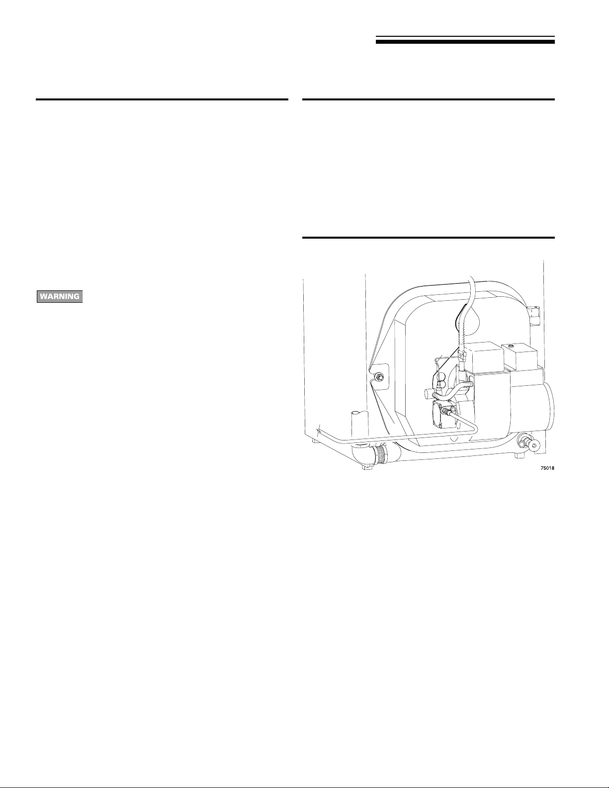
Oil-Fired Water Boilers
Boiler Manual
Contents Page
1 Prepare boiler location ........................................................2
2 Prepare boiler ..................................................................... 5
3 Connect breeching .............................................................6
4 Connect water piping ..........................................................7
5 Connect tankless heater piping.........................................10
6 Connect wiring..................................................................11
7 Connect oil piping .............................................................14
8 Start-up ............................................................................15
9 Checkout procedure .........................................................16
10 Appendix ..........................................................................17
11 Service and maintenance ................................................. 1 8
12 Replacement parts ........................................................... 22
13 Dimensions ......................................................................26
14 Ratings .............................................................................27
Hazard definitions
Hazards that will cause severe personal injury,
death or substantial property damage.
Hazards that can cause severe personal injury,
death or substantial property damage.
INSTALLER — Read all instructions before
installing. Read page 2 first. Follow all instructions
in proper order to prevent personal injury or death.
• Consider piping and installation when determining
boiler location.
• Any claims for damage or shortage in shipment
must be filed immediately against the transportation
company by the consignee.
This manual must only be used by a qualified heating installer/service technician. Boiler and burner must be installed
and serviced only by a qualified heating installer/service technician. Failure to comply could result in se vere personal injury ,
death or substantial property damage.
When calling or writing about the boiler— Please have: • boiler model number from the boiler rating label and • CP number
from the boiler jacket. You ma y list the CP number in the space provided on the “Installation and service certificate” found on
page 16.
Hazards that will or can cause minor personal injury
or property damage.
Special instructions on installation, operation or
maintenance that are important but not related to
personal injury or property damage .
USER — Please read the following. Failure to
comply could result in severe personal injury , death
or substantial property damage.
• This manual is for use only by your qualified
heating installer/service technician.
• Please see the User’s Inf ormation Manual for your
reference.
• Have the boiler serviced by a qualified service
technician, at least annually .
Part Number 672 01 1005 00
Page 2

OWB & OWT
Oil-Fired Water Boilers – Boiler Manual
1 Prepare boiler locationRead this first!
Failure to adhere to the guidelines below can
result in severe personal injury, death or
substantial property damage.
When servicing boiler —
1. To avoid electric shock, disconnect electrical supply
before performing maintenance.
2. To avoid severe burns, allow boiler to cool before
performing maintenance.
Boiler operation —
3. Do not bloc k flow of combustion or v entilation air to boiler.
4. Should overheating occur, do not turn off or disconnect
electrical supply to circulator. Instead, shut off the oil
supply at a location external to the appliance, if possible.
5. Do not use this boiler if any part has been under water.
Immediately call a qualified service technician to inspect
the boiler and to replace any part of the control system
and any burner control that has been under water .
Boiler water —
6. DO NOT use petroleum-based cleaning or sealing
compounds in boiler system. Water seal deterioration will
occur, causing leakage between boiler sections, circulator
flanges, diaphragm tanks or other system components.
This can result in substantial property damage.
7. DO NOT use "homemade cures" or "boiler patent
medicines". Serious damage to boiler , personnel and/or
property may result.
8. Continual fresh makeup water will reduce boiler life. Mineral
buildup in sections reduces heat transfer , ov erheats cast
iron, and causes section failure. Addition of oxygen and
other gases can cause internal corrosion. Leaks in boiler
or piping must be repaired at once to prevent makeup
water .
9. Do not add cold water to hot boiler. Thermal shock can
cause sections to crack.
Glycol — potential fire hazard —
All glycol is flammable when exposed to high temperatures. If
glycol is allowed to accumulate in or around the boiler or any
other potential ignition source, a fire can dev elop. In order to
prevent potential se vere personal injury , death or substantial
property damage from fire and/or structural damage:
• Never store glycol of any kind near the boiler or any
potential ignition source.
• Monitor and inspect the system and boiler regularly for
leakage. Repair any leaks immediately to prevent possible
accumulation of glycol.
• Never use automotive antifreeze or ethylene glycol in the
system. Using these glycols can lead to hazardous
leakage of glycol in the boiler system.
Codes & checklist
Installations must follow these codes:
• Local, state, provincial, and national codes, laws, regulations
and ordinances.
• NFP A-31, Installation of Oil-Burning Equipment.
• Standard for Controls and Safety Devices for Automatically
Fired Boilers, ANSI/ASME CSD-1, when required.
• National Electrical Code.
• For Canada only: B149.1 or B149.2 Installation Code, CSA
C22.1 Canadian Electrical Code Part 1 and any local codes.
Certification
The OWB and OWT boilers, burners and controls
met safe lighting and other performance criteria when
boiler underwent tests specified in CSA B140.0 and
B140.7.1.
Before locating the boiler:
❏ Check for nearby connection to:
• System water piping
• V enting connections (page 6)
• Combustion and ventilation air provisions (page 4)
• Oil supply piping (page 14 and burner manual)
• Electrical power
❏ Check area around boiler. Remov e any combustible materials,
gasoline and other flammable liquids.
Failure to keep boiler area clear and free of
combustible materials, gasoline and other flammable
liquids and vapors can result in severe personal
injury, death or substantial property damage.
❏ Boiler must be installed so that burner and control system
components are protected from dripping or spraying water or
rain during operation or service.
❏ If new boiler will replace existing boiler, chec k f or and correct
system problems, such as:
1. System leaks causing oxygen corrosion or section cracks
from hard water deposits.
2. Incorrectly-sized expansion tank.
3. Lack of antifreeze (when required) in boiler water causing
system and boiler to freeze and leak.
2 Part Number 672 01 1005 00
Page 3
OWB & OWT
Oil-Fired Water Boilers – Boiler Manual
1 Prepare boiler location
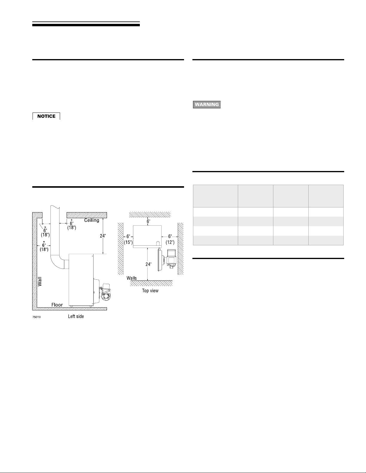
Clearances Flooring and foundation
Minimum clearance to combustible materials
1. Minimum clearances from vent pipe to combustible material (see
Figure 1, vent clearances indicated with “*”):
• Type “L” double wall vent — 6 inches minimum
• Singlewall vent — 18 inches minimum
Flue pipe clearances must take precedence over
jacket clearances (listed below).
Service clearances
1. Recommended service clearances (see Figure 1):
• Front and top — 24 inches
• Left side, back and right side — 6 inches
• Right side for burner door swing radius — 12 inches
2. Special close clearances (alcove, closet, under counters, etc.)
– see “Appendix,” page 17.
Figure 1 Minimum clearances
Flooring
The OWB and OWT boilers are approved for installation on
combustible flooring, but must never be installed on carpeting.
Do not install boiler on carpeting even if foundation is
used. Fire can result, causing se vere personal injury ,
death or substantial property damage.
Foundation
1. Provide a solid brick or minimum 2-inch thick concrete
foundation pad if any of the following is true:
• floor can become flooded.
• the boiler mounting area is not level.
2. See T ab le 1 for minimum f oundation dimensions.
Table 1 Minimum foundation size
Boiler
model
number
OWB/OWT3 17 22 2
OWB/OWT4 17 22 2
OWB/OWT5 20 22 2
OWB/OWT6 23 22 2
Length
inches
Width
inches
Minimum
height
inches
Residential garage installations
T ake the f ollowing special precautions when installing the boiler in
a residential garage. If the boiler is located in a residential garage:
• Mount the boiler a minimum of 18 inches above the floor of the
garage to ensure the burner and ignition devices will be no less
than 18 inches above the floor .
• Locate or protect the boiler so it cannot be damaged by a moving
vehicle.
3Part Number 672 01 1005 00
Page 4
OWB & OWT
Oil-Fired Water Boilers – Boiler Manual
1 Prepare boiler location continued
Air contaminationAir for combustion and ventilation
Adequate combustion and ventilation air:
• Assures proper combustion.
• Reduces risk of severe personal injury or death from
possible flue gas leakage and carbon monoxide
emissions.
• Do not install exhaust fan in boiler room.
Consider building construction
Older buildings with single-pane windows, minimal weather-stripping
and no vapor barrier often provide enough natural infiltration and
ventilation without dedicated openings.
New construction or remodeled buildings are most often built tighter .
Windows and doors are weather-stripped, vapor barriers are used
and openings in walls are caulked. As a result, such tight
construction is unlikely to allow proper natural air infiltration and
ventilation.
Follow state, provincial or local codes when sizing adequate
combustion and ventilation air openings. In absence of codes, use
the following guidelines when boiler is in a confined room (defined
by NFPA 31 as less than 7200 cubic feet per 1 GPH input of all
appliances in area. A room 8 ft. high x 30.0 ft. x 30.0 ft. is 7200 cu.
ft.).
Provide two permanent openings:
One within 12 inches of ceiling, one within 12 inches of floor. Minimum
height or length dimension of each rectangular opening should be
at least 3 inches.
When inside air is used:
Each opening must freely connect with areas having adequate
infiltration from outside. Each opening should be at least 140 sq. in.
per 1 GPH input (1 sq. in. per 1000 Btu input) of all fuel-burning
appliances plus requirements for any equipment that can pull air
from room (including clothes dryer and fireplace).
When outside air is used:
Connect each opening directly or by ducts to the outdoors or to
crawl or attic space that freely connects with outdoors. Size per
below:
• Through outside wall or vertical ducts — at least 35 sq. in. per
1 GPH input (1 sq. in. per 4000 Btu input) of all fuel burning
appliances plus requirements for any equipment that can pull
air from room (including clothes dryer and fireplace).
• Through horizontal ducts — at least 70 sq. in. per 1 GPH boiler
input (1 sq. in. per 2000 Btu input) of all fuel-burning appliances
plus requirements for any equipment that can pull air from room
(including clothes dryer and fireplace).
• Where ducts are used, they should have same cross-sectional
area as free area of openings to which they connect.
Compensate for louver, grille or screen blockage when
calculating free air openings. Refer to their manufacturer’s
instructions for details. If unknown, use:
• Wood louvers , which provide 20-25% free air.
• Metal louvers or grilles, which provide 60-75% free air .
Lock louvers in open position or interlock with equipment to
prove open before boiler operation.
Please review the following information on potential combustion air
contamination problems.
See Tab le 2 for products and areas which may cause contaminated
combustion air .
T o prev ent potential of severe personal injury or death,
check for products or areas listed below before
installing boiler. If any of these contaminants are found:
• remove contaminants permanently .
— OR —
• isolate boiler and provide outside combustion air. See
national, provincial or local codes for further
information.
Table 2 Corrosive contaminants and likely locations
Products to avoid
Spray cans containing chloro/fluorocarbons
Permanent wave solutions
Chlorinated waxes/cleaners
Chlorine-based swimming pool chemicals
Calcium chloride used for thawing
Sodium chloride used for water softening
Refrigerant leaks
Paint or varnish removers
Hydrochloric acid/muriatic acid
Cements and glues
Antistatic fabric softeners used in clothes dryers
Chlorine-type bleaches, detergents, and cleaning solvents found in
household laundry rooms
Adhesives used to fasten building products and other similar products
Areas likely to have contaminants
Dry cleaning/laundry areas and establishments
Swimming pools
Metal fabrication plants
Beauty shops
Refrigeration repair shops
Photo processing plants
Auto body shops
Plastic manufacturing plants
Furniture refinishing areas and establishments
New building construction
Remodeling areas
Garages with workshops
4 Part Number 672 01 1005 00
Page 5

2 Prepare boiler
OWB & OWT
Oil-Fired Water Boilers – Boiler Manual
Place boiler
The boiler contains ceramic fiber and fiberglass
materials. Use care when handling these materials
per instructions on page 21 of this manual. F ailure to
comply could result in severe personal injury .
1. Remov e circulator carton strapped to pallet.
Circulator will be damaged if not removed before boiler
is lifted from pallet.
2. Remove boiler from pallet.
Do not drop boiler or bump jacket or burner on floor
or pallet. Damage to boiler or burner can result.
Smaller sized boilers may be top heavy . Use caution
when handling to avoid minor personal injury or
property damage.
3. Check level. Shim legs if needed.
4. Open burner mounting door. V erify that chamber ceramic liner
is securely in place on target wall, chamber floor and burner
door. V erify door seal is intact and in place. Close and securely
bolt the door.
6. Visually check:
a. Flue collector hood seal.
b . Burner mounting door seal.
Obtain gas-tight seal to prevent possible flue gas
leakage and carbon monoxide emissions, which can
lead to severe personal injury or death.
Hydrostatic pressure test
1. Install air vent in air vent tapping on top of boiler (see Figure 20,
page 26, for location).
3. Plug supply and return tappings.
4. Drain valve is factory-installed.
5. Fill boiler. V ent all air. Pressure test boiler at 1 ½ times w orking
pressure.
Do not leave boiler unattended. Cold water fill can
expand and damage cast iron, resulting in severe
personal injury, death or substantial property damage.
6. Verify that boiler maintains pressure for at least 10 minutes.
Visually check for leaks if gauge pressure drops.
7. Drain boiler. Repair leaks if f ound.
Using petroleum-based compounds to repair leaks
can damage system components, resulting in
property damage.
8. Retest boiler after repairing leaks.
9. Remove air vent and plugs.
5Part Number 672 01 1005 00
Page 6
OWB & OWT
Oil-Fired Water Boilers – Boiler Manual
3 Connect breeching
General venting requirements
Failure to follo w all instructions can result in flue gas
spillage and carbon monoxide emissions, causing
severe personal injury or death.
Inspect existing chimney before installing boiler.
Insufficient draft can cause flue gas leakage and
carbon monoxide emissions. Failure to clean or
replace perforated pipe or tile lining and/or patch
mortar and joints can cause severe personal injury
or death.
• The OWB and OWT boilers are designed to operate with an
over-fire draft of -0.01" to -0.02" w.c. Proper draft f or these oil
boilers may be achieved using either a conventional chimney
(natural draft) or a power vent (sidewall) system that has been
properly designed for use with oil-fired equipment. Pow er vent
manufacturer’s instructions must be f ollowed.
• Use vent material approved by local codes for oil-fired burners.
In their absence, refer to:
• NFP A 31, Installation of Oil-Burning Equipment.
• NFP A 211, Standard f or Chimneys, Fireplaces , Vents and
Solid Fuel Burning Appliances.
• In Canada, refer to CSA B139, Installation Code for Oil-
Burning Equipment.
• NFPA 211 requires chimney to be lined before connected
to boiler.
• To prevent downdrafts, extend chimney at least 3 feet above
highest point where it passes through roof and 2 feet higher
than any portion of building within 10 feet. Increase chimney
cross-sectional area and height at least 4% per 1,000 feet above
sea level.
• Provide minimum clearances from vent (flue) pipe to combustible
material:
• Type “L” double wall vent — 6 inches minimum
• Singlewall vent — 18 inches minimum
• Minimum chimney sizes should be used. See Table 3.
Oversized chimneys, outside masonry chimneys
and/or derated inputs can result in condensation in
chimney.
Connect breeching
Long horizontal breechings, excessive number of
tees and elbows, or other obstructions restricting
combustion gas flow can result in possibility of
condensation, flue gas leakage and carbon monoxide
emissions, which can lead to severe personal injury
or death.
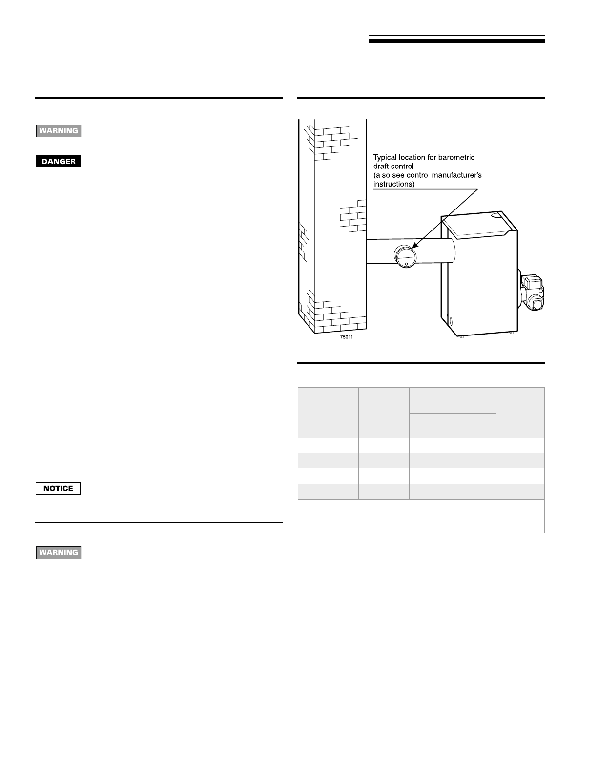
1. See Figure 2.
2. Connect full-sized breeching when possible. See Table 3.
3. Connection must be made above bottom of chimney to avoid
blockage. Breeching must not enter chimney far enough to
Figure 2 Chimney and breeching connections
Table 3 Chimney and breeching minimum sizes
Boiler
model
number
OWB/OWT3 5" 8" x 8" 6" 15'
OWB/OWT4 6" 8" x 8" 6" 15'
OWB/OWT5 6" 8" x 8" 7" 15'
OWB/OWT6 7" 8" x 8" 7" 15'
Notes:
1. Flue collar on boiler is7" diameter
2. 6 ¾"x6¾"insideliner
cause obstruction. Use thimble or slip joint where breeching
enters chimney to allow removal for cleaning.
4. When burner and boiler are properly installed, draft overfire will
be approximately -0.01" to -0.02" W .C . Install barometric control
in breeching, per control manufacturer's instructions, when
excess draft needs to be relieved or to comply with applicable
codes and regulations. Use draft gauge to adjust proper opening.
5. An induced draft fan for the chimney may be necessary if:
• Excessive resistance to flow of combustion gases can be
expected.
• Cross-sectional area of chimney is smaller than minimum
recommended.
• Chimney height is less than recommended.
• Seal all vent joints. Interlock burner with fan operation.
Minimum
breeching
diameter
Note 1
Minimum I=B=R
chimney size
Rectangle
Note 2
Round
Minimum
chimney
height
6 Part Number 672 01 1005 00
Page 7

OWB & OWT
4 Connect water piping
Oil-Fired Water Boilers – Boiler Manual
General
If installation is to comply with ASME or Canadian requirements,
an additional high temperature limit is needed. Install control in supply
piping between boiler and isolation valve. Set second control to
minimum 20 °F above setpoint of first control. Maximum allowable
setpoint is 240 °F. See page 11 for wiring.
A low water cutoff device is required when boiler is installed above
radiation level or by cer tain state or local codes or insurance
companies. Use low water cutoff designed for water installations.
Electrode probe-type is recommended. Purchase and install in tee
in supply piping above boiler .
Use backflow check valve in cold water supply if required by local
codes.
Near -boiler piping
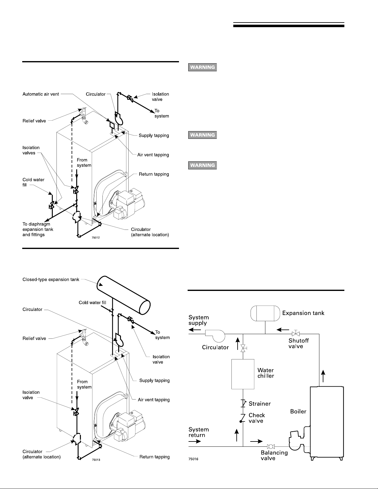
See Figure 3 (diaphragm-type or bladder-type expansion tank) or
Figure 4 (closed-type expansion tank) on page 8, and Table 4, for
near-boiler and single-zone systems designed for return water at
least 130 °F. See Figure 6 or 7, page 9 for low return temperature
applications.
See this page for multiple-zone piping.
See page 8 for boilers used with refrigeration systems.
Relief valve
Install relief valve v ertically in ¾" tapping on rear of boiler using ¾"
nipple and elbow supplied in bag with valve. See the tag attached to
the relief valve f or manufacturer’s instructions.
To avoid water damage or scalding due to valve
operation, discharge line must be connected to relief
valve outlet and run to a safe place of disposal.
T erminate the discharge line to eliminate possibility
of severe burns should the valve discharge.
• Discharge line must be as short as possible and be
the same size as the valve discharge connection
throughout its entire length.
• Discharge line must pitch downward from the valve
and terminate at least 6" above the floor drain where
any discharge will be clearly visible.
• The discharge line shall terminate plain, not threaded,
with a material serviceable for temperatures of 375 °F
or greater.
• Do not pipe the discharge to any place where freezing
could occur.
• No shutoff valve shall be installed between the relief
valve and boiler , or in the discharge line. Do not plug
or place any obstruction in the discharge line.
• Failure to comply with the above guidelines could
result in failure of the relief valve to operate, resulting
in possibility of severe personal injury, death or
substantial property damage.
• Test the operation of the valve after filling and
pressurizing system by lifting the lever. Make sure
the valve discharges freely. If the valve f ails to operate
correctly , replace it with a new relief v alv e.
Near -boiler piping continued
Table 4 Water pipe size (based on 20 °F rise)
Boiler
model
number
OWB/OWT3 1 ¼" 1 ¼"
OWB/OWT4 1 ¼" 1 ¼"
OWB/OWT5 1 ½" 1 ½"
OWB/OWT6 1 ½" 1 ½"
All piping sizes based on 20 °F temperaturerise through boiler.
Circulator
The circulator is shipped loose (wiring pre-attached to boiler) to
allow you to locate it either in the return or supply piping, as desired.
See page 8 for a typical installation. Pipe the expansion tank to the
suction side of the circulator whenever possible. Install an air
separator in the supply piping. Connect the expansion tank to the
air separator only if the separator is on the suction side of the
circulator. Always install the system fill connection at the same point
as the expansion tank connection to the system. Figures 3 and 4,
on page 8, show typical near-boiler piping connections.
Expansion tank
Diaphragm- or bladder-type expansion tank — Figur e 3,
page 8
1. Ensure expansion tank size will handle boiler and system water
volume and temperature. T ank m ust be located in boiler return
piping as close to boiler as possible, bef ore inlet side of circulator.
See tank manufacturer’s instructions for details.
2. Install an automatic air vent as shown.
Closed-type expansion tank — Figure 4, page 8
1. Ensure expansion tank size will handle boiler and system water
volume and temperature. See tank manuf acturer’s instructions
for details.
2. Connect tank to ½" NPT tapping located behind supply outlet,
using ½" NPT piping. Pitch any horizontal piping up towards
tank 1 inch per 5 feet of piping.
Undersized expansion tanks cause system water to
be lost from relief valve and makeup water to be
added through fill valve. Eventual section failure can
result.
Water piping — multiple zone systems
Install system piping using either circulator zoning or zone valve
zoning. Install expansion tank on suction side of system pump.
Always connect fill line only at the expansion tank — never at
another point in the system.
To
system
From
system
7Part Number 672 01 1005 00
Page 8
OWB & OWT
Oil-Fired Water Boilers – Boiler Manual
4 Connect water piping continued
Figure 3 Diaphragm- or bladder-type expansion tank:
Piping to single-zone system using
diaphragm-type or bladder-type expansion
tank. See Table 4, page 7, for piping sizes.
Figure 4 Closed-type expansion tank: Piping to
single-zone system using closed-type
expansion tank. See Table 4, page 7, for
piping sizes.
Use Figure 3 or Figure 4 only for systems designed
for return water at least 130 °F. For systems with low
return water temperature possible, such as
converted gravity systems and radiant heating
systems, install by-pass piping (see page 9) to protect
boiler against condensation. Failure to prevent low
return water temperature to the boiler could cause
corrosion of the boiler sections or burners, resulting
in severe personal injury, death or substantial
property damage.
If system includes radiant heating circuits, provide
piping and controls to regulate the temperature
supplying the radiant circuits. Failure to comply could
result in substantial property damage.
Install boiler so that chilled medium is piped in parallel
with heating boiler. Use appropriate valves to pre vent
chilled medium from entering boiler. Consult I=B=R
Installation and Piping Guides.
If boiler is connected to heating coils located in air
handling units where they can be exposed to
refrigerated air, use flow control valves or other
automatic means to prevent gravity circulation during
cooling cycle. Circulation of cold water through the
boiler could result in damage to the heat exchanger ,
causing possible severe personal injury, death or
substantial property damage.
Water piping — refrigeration systems
Prevent chilled water from entering boiler
Install boiler so that chilled medium is piped in parallel with the
heating boiler. Use appropriate valves to prevent chilled medium
from entering boiler. See Figure 5 for typical installation of balancing
valve and check valve.
Figure 5 Piping refrigeration systems
8 Part Number 672 01 1005 00
Page 9
OWB & OWT
4 Connect water piping continued
Near -boiler piping continued
Oil-Fired Water Boilers – Boiler Manual
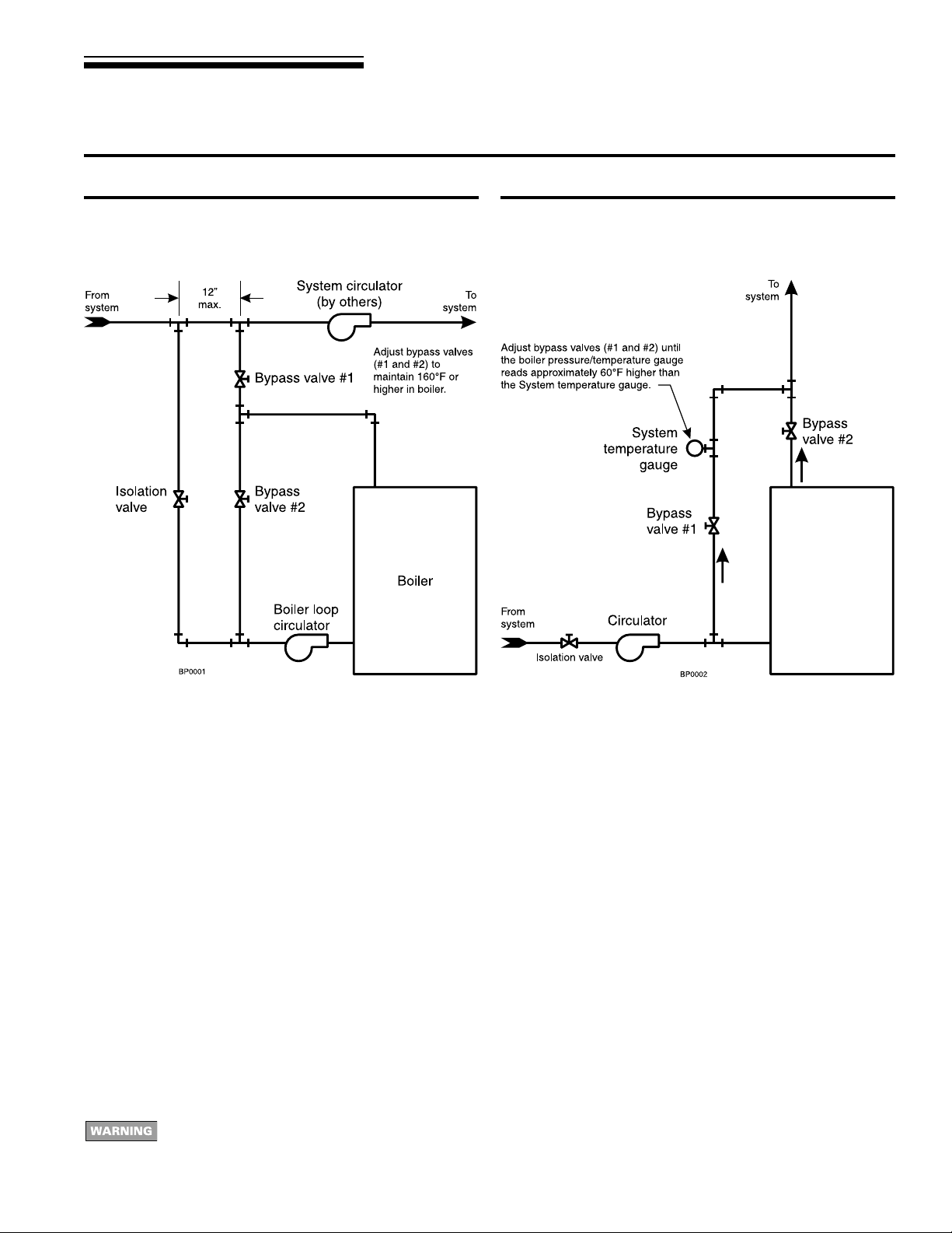
Figure 6 System bypass piping in boiler loop with
separate system circulator, using primary/
secondary piping.
Figure 7 Boiler bypass piping — use only for high
water content systems —DO NOT use for
radiant panel systems.
System bypass method
1. Apply bypass piping of Figure 6 to high water content systems,
radiant panel systems or any system that is likely to operate
with low return water temperature for extended periods.
2. The bypass arrangement shown protects the boiler from damage
caused by condensate corrosion due to low return water
temperature and protects low temperature systems from too
high a supply temperature.
3. Adjust the bypass valves as indicated below .
Adjust Bypass valves 1 and 2 as follows:
1. Start with valve 2 fully closed, valv e 1 fully open.
2. Slowly open valve 2 while closing valve 1. Adjust the valves
until the boiler pressure/temperature gauge reads 160 °F or
higher. As you open the valves, pause long enough to allow
temperatures to level off. It takes a while for the boiler water
temperature to rise as the flow changes.
3. Bypass valve 2 allows hot boiler outlet water to blend with colder
return water, raising the supply temper ature to the boiler. Bypass
valve 1 balances the pressure drop through valve 2.
4. The purpose of this piping is to raise the return water temperature
to the boiler enough to prevent condensation of flue gases.
Install all components specified above and adjust valv es as described to prev ent low temper ature in the boiler . Fa ilure to
prevent low water temperature in the boiler could cause corrosion of the boiler sections or burners, resulting in severe
personal injury, death or substantial property damage.
Boiler bypass method
1. Apply bypass piping of Figure 7 to high water content systems,
such as converted gravity systems.
2. The bypass arrangement shown protects the boiler from damage
caused by condensate corrosion due to low return water
temperature. This method does not pro vide protection from high
temperature water being supplied to the system.
3. DO NOT apply this piping to radiant panel systems.
4. Adjust the bypass valves as indicated below .
Adjust Bypass valves 1 and 2 as follows:
1. Start with valve 1 fully closed, valv e 2 fully open.
2. Slowly open valve 1 while closing valve 2. Adjust the valves
until the boiler pressure/temperature gauge reads approximately
60 °F higher than the system temperature gauge. As you open
the valves, pause long enough to allow temperatures to level
off. It takes a while for the boiler water temperature to rise as
the flow changes.
3. Bypass valve 1 controls system flow rate. Bypass valve 2
controls flow through the boiler.
4. The purpose of this piping is to cause a high enough temperature
rise in the boiler that the average temperature will be warm
enough to prevent condensation of flue gases.
9Part Number 672 01 1005 00
Page 10
OWB & OWT
Oil-Fired Water Boilers – Boiler Manual
5 Connect tankless heater piping (OWT boilers only)
Hot water can scald!
• Consumer Product Safety Commission and some
states recommend domestic hot water temperature
of 130 °F or less.
• When installing an automatic mixing valve, selection
and installation must comply with valve man ufacturer’s
recommendations and instructions.
• Water heated to a temperature suitable for clothes
washing, dish washing and other sanitizing needs
will scald and cause injury.
• Children and elderly , infirm or physically handicapped
persons are more likely to be injured by hot water.
Never leave them unattended in or near a bathtub,
shower or sink. Never allow small children to use a
hot water faucet or draw their own bath. If anyone
using hot water in the building fits this description, or
if state laws or local codes require certain water
temperatures at hot water faucets, take special
precautions:
• Install automatic mixing valve set according to those
standards.
• Use lowest practical temperature setting.
• Check water temperature immediately after first
heating cycle and after any adjustment.
Studies have indicated that dangerous bacteria can
form in potable water distribution systems if certain
minimum water temperatures are not maintained.
Contact local health department for more information.
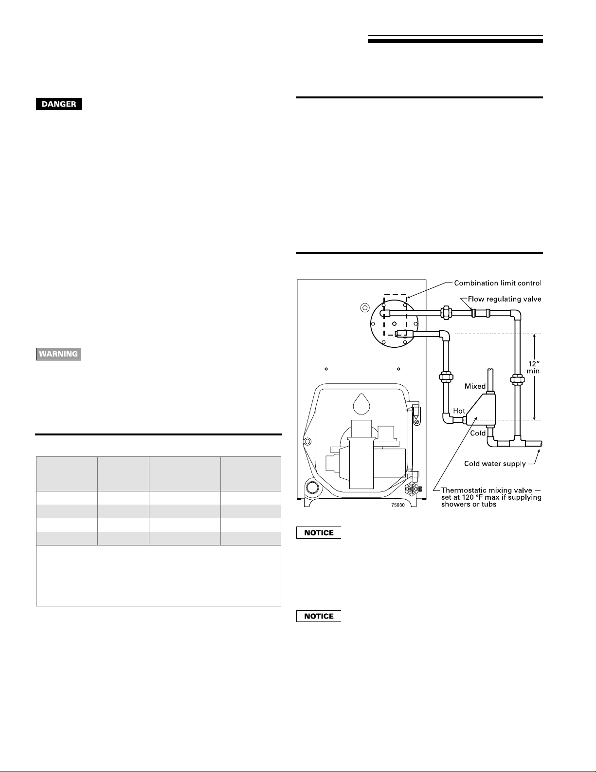
Pipe tankless heater
1. Size piping no smaller than tankless heater inlet and outlet.
2. Following controls (furnished by others) must be installed:
a. Automatic mixing valve. See Figure 8. (Read DANGER
statement at left.)
b. Flow regulating valve (see Figure 8). Size according to
intermittent draw of tankless heater. See Table 5. Follow
valve man ufacturer’s instructions to install.
3. Additional anti-scald devices may be installed at each hot water
faucet, bath and shower outlet.
4. In hard water areas, soften cold domestic supply water to
heaters to prevent lime buildup .
Figure 8 Piping connections to tankless heater, typical
Table 5 Tankless heater ratings
Boiler
model
number
OWB/OWT-3 WT-11 3.00
OWB/OWT-4 WT-14 3.75
OWB/OWT-5 WT-14 4.00
OWB/OWT-6 WT-14 4.25
Note 1: Gallons of water per minute heated from 50˚F to 140˚F with
200˚F boiler water temperature.
Note 2: Gallons of water per minute heated from 40˚F to 140˚F with
200˚F boiler water temperature.
Tested in accordance with I=W=H Testing and Rating Standard for
Indirect Tankless Water Heaters Tested with Boilers.
Heater
number
Intermittent
draw ratings
(GPM)
(note 1)
(note 2)
(note 2)
(note 2)
Inlet and
outlet
tapping sizes
¾"
¾"
¾"
¾"
These single wall heat exchangers comply with
National Standard Plumbing Code provided that:
• Boiler water (including additives) is practically
nontoxic, having toxicity rating or class of 1, as listed
in Clinical Toxicology of Commercial Products.
• Boiler water pressure is limited to maximum 30 psig
by approved water relief valve.
Tankless heater ratings are based on 200°F boiler
water temperature. To get rated output, set tankless
heater control to 200°F. Control can be adjusted to
meet system hot water requirements.
10 Part Number 672 01 1005 00
Page 11

6 Connect wiring
OWB & OWT
Oil-Fired Water Boilers – Boiler Manual
Electric shock hazard. Can cause severe personal
injury or death if power source, including service
switch on boiler , is not disconnected before installing
or servicing.
Installations must follow these codes:
• National Electrical Code, ANSI/NFP A 70, latest edition and an y
additional national, state or local codes.
• In Canada, CSA C22.1 Canadian Electrical Code Part One and
any local codes.
• Wiring must be N.E.C. Class 1. If original wire as supplied with
boiler must be replaced, type 105 °C wire or equivalent must
be used. Supply wiring to boiler and additional control wiring
must be 14 gauge or heavier.
• Provide electrical ground at boiler as required by codes.
Thermostat wiring
• Install thermostat on inside wall away from influences of drafts,
hot or cold water pipes, lighting fixtures, television, sun rays or
fireplaces.
• Follow instructions with thermostat. If it has a heat anticipator,
set heat anticipator in thermostat to match power requirements
of equipment connected to it. Boiler wiring diagrams give setting
for standard equipment.
Figure 9 Electrical components and harnesses
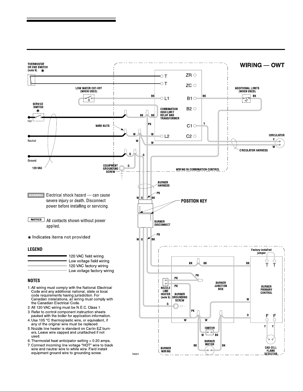
Burner wiring
• Burner harness incorporates a disconnect plug, providing a
convenient way to disconnect wiring when burner mounting door
is opened. See Figure 9.
Wiring entrance
• The limit control enclosure houses electrical connections for all
boiler components.
• Boilers have harnesses furnished. See Figure 10, page 12,
(OWB boilers) or Figure 11, page 13, (OWT boilers) for factory
and field wiring information.
• All field-installed high voltage wiring must be sheathed in metal
conduit.
• Connect incoming line voltage wires as shown in Figure 10 or
Figure 11. Field-install equipment ground wire to green wire with
wire nut.
• Some local codes may require an emergency shut-off switch
installed at a location away from boiler . Follo w local codes.
11Part Number 672 01 1005 00
Page 12

OWB & OWT
Oil-Fired Water Boilers – Boiler Manual
6 Connect wiring continued
Figure 10 Wiring diagram — OWB boilers
12 Part Number 672 01 1005 00
Page 13
OWB & OWT
6 Connect wiring continued
Figure 11 Wiring diagram — OWT boilers
Oil-Fired Water Boilers – Boiler Manual
13Part Number 672 01 1005 00
Page 14
OWB & OWT
Oil-Fired Water Boilers – Boiler Manual
7 Connect oil piping
General oil piping requirements
• Location and installation of oil tanks, oil piping and burners must
follow:
• NFPA 31, Standard for the Installation of Oil-Burning
Equipment.
• In Canada, CSA B139, Installation of Oil-Burning Equipment.
• Local codes and regulations.
• Information provided with burner and fuel pump.
• If any part of fuel oil tank is above level of burner , an anti-siphon
device must be used to prevent flow of oil in case of oil line
break.
• Support oil lines as required by codes.
• Make tank connections with swing joints or copper tubing to
prevent breaking in case the tank settles. Make swing joints so
they will tighten as tank settles. Non-hardening pipe joint
compounds should be used on all threads.
Do not use Teflon tape as an oil pipe sealant. It can
cause valves to fail, creating hazards. Use only flare
fittings. Do not use compression fittings. Failure to
comply could result in severe personal injury, death
or substantial property damage from oil leakage and/
or fire hazard.
• Underground pipe must be run in a casing to prevent oil leaking
into ground or under floor. Check local codes f or information.
Oil piping connection at burner
• See Figure 12 for typical oil connection at burner, allo wing burner
mounting door to swing open completely for servicing.
• Connect oil line to burner using flare fitting (Figure 12).
• See local codes for appropriate arrangement and piping of filter,
control valves, etc. connecting to oil tank.
• Refer to burner manual for oil sytem requirements. Verify that
suction lift does not exceed stated limit. Where lift e xceeds limit
for a one-pipe system, use a two-pipe system as directed in
burner manual.
Figure 12 Oil piping connection to burner , typical
14 Part Number 672 01 1005 00
Page 15

8 Start-up
OWB & OWT
Oil-Fired Water Boilers – Boiler Manual
Follow information below to prevent severe personal
injury, death or substantial property damage:
• Do not use gasoline crankcase drainings or any oil
containing gasoline. See burner manual for proper
fuel oil.
• Do not attempt to start burner when excess oil has
accumulated, when unit is full of vapor or when
combustion chamber is very hot.
• Do not start burner unless collector hood, breeching
and burner mounting door are secured in place.
• Never b urn garbage or paper in the boiler.
• Never leave combustible material around it.
Fill the system
1. Close manual and automatic air vents and boiler drain cock.
2. Fill to correct system pressure. Correct pressure will vary with
each installation. Normal cold water fill pressure for residential
systems is 12 psig. Boiler water pH 7.0 to 8.5 is recommended.
Failure to maintain recommended pH le vel can cause
section failure and leaks.
3. Open automatic air vent one turn.
4. Open other vents.
a. Starting on the lowest floor, open air vents one at a time
until water squirts out. Close vent.
b . Repeat with remaining vents.
5. Refill to correct pressure.
Tips for water systems
• Check boiler and system piping for leaks. Continual makeup
water will reduce boiler life. Minerals can build up in sections,
reducing heat transfer and causing cast iron to overheat,
resulting in section failure.
Failure to maintain recommended pH and repair leaks
can cause section iron corrosion, leading to section
failure and leaks. Do not use petroleum-based sealing
or stop-leak compounds in boiler system. Damage
to system components can result.
• For pH conditions outside 7.0 to 8.5 range or unusually hard
water areas (above 7 grains hardness), consult local water
treatment company .
• When using antifreeze:
Do not use automotive, ethylene glycol, undiluted
or petroleum-based antifreeze. Severe personal
injury, death or substantial property damage can
result.
• Use antifreeze especially made for hydronic systems. Inhibited
propylene glycol is recommended.
• 50% solution provides protection to about -30 °F. Do not exceed
50% mixture.
• Local codes may require backflow preventer or actual
disconnect from city water supply.
• Determine quantity according to system water content. Boiler
water content is listed on back cover of manual. Percent of
solution will affect sizing of heat distribution units, circulator
and expansion tank.
• Follow antifreeze man ufacturer’s instructions.
Place in operation
1. Verify boiler is filled with water.
2. Open burner mounting door and verify rear target wall, floor
and burner door insulations are in proper position and condition.
3. V erify burner mounting door is closed tightly and burner wiring
harness is connected securely.
4. Factory burner adjustment and settings may not be suitable
for specific job conditions. Refer to burner manual for burner
start-up, adjustment and checkout procedures.
5. Refer to burner manual for start-up. Allow boiler to heat to
design temperature. Then adjust b urner for correct combustion,
using combustion test equipment. Adjust burner for:
Draft: –0.01 to –0.02 inches water column draft in boiler
combustion chamber.
: between 11% and 12%, with 0 smoke.
CO
2
Make final burner adjustments using combustion
test equipment to assure proper operation. Do not
fire boiler without water. Sections will overheat,
damaging boiler and resulting in substantial property
damage.
6. Vent air from system. Repeat steps 4 and 5 under “Fill the
system”. Air in system can interfere with water circulation and
cause improper heat distribution.
7. Check boiler and system piping for leaks. See “Tips for water
systems” on this page.
8. Inspect breeching and venting for proper operation.
For additional information, refer to instructions packed with boiler or burner:
• Burner Manual
• Component literature
15Part Number 672 01 1005 00
Page 16

OWB & OWT
Oil-Fired Water Boilers – Boiler Manual
9 Checkout procedure
Check off steps as completed
❑ 1. Boiler and heat distribution units filled with water?
❑ 2. Automatic air vent, if used, opened one full turn?
❑ 3. Air purged from system? Piping checked for leaks?
❑ 4. Air purged from oil piping? Piping checked for leaks?
❑ 5. Burner door closed, sealed and nut tight? Burner harness
securely plugged in?
Obtain gas-tight seal to prevent possible flue gas
leakage and carbon monoxide emissions, leading to
severe personal injury or death.
❑ 6. Proper draft and burner flame? Final adjustment made
with combustion test equipment?
❑ 7. T est limit control: While burner is operating, move indicator
on limit control below actual boiler water temperature.
Burner should go off while circulator continues to operate.
Raise setting on limit control above water temperature and
burner should reignite.
❑ 8. Test additional field-installed controls: If boiler has a lo w
water cutoff, additional high limit or other controls, test for
operation as outlined by manuf acturer. Burner should be
operating and should go off when controls are tested. When
controls are restored, burner should reignite.
❑ 9. Limit control set to system temperature requirements
(maximum 220 °F)?
❑ 10. For multiple zones, flow adjusted to distribute heat in all
zones?
❑ 11. Thermostat heat anticipator setting (if available) set
properly? Refer to “Connect wiring, ” page 11.
❑ 12. Boiler cycled with thermostat? Raise to highest setting
and verify boiler goes through normal start-up cycle. Lower
to lowest setting and verify boiler goes off.
❑ 13. Observed several operating cycles for proper operation?
❑ 14. Set room thermostat(s) to desired room temperature?
❑ 15. Completed “Installation and service certificate” below?
❑ 16. Reviewed User’s Information Manual with owner or
maintenance person and instructed person to keep for
future reference?
❑ 17. Returned all instructions provided with boiler to its envelope
and placed with boiler for future reference?
Installation and service certificate
Boiler model _______________________________________________________________ Series ____________
CP number _______________________________________ Date installed _________________________________
o Installation instructions have been followed.
Measured Btuh input ____________
Installer _______________________ ______________________________ ____________________________
(company) (address) (phone)
16 Part Number 672 01 1005 00
o Checkout sequence has been performed.
o Above information is certified to be correct.
o Information received and left with owner/maintenance person.
_____________________________________
(installer’s signature)
Page 17

10 Appendix
OWB & OWT
Oil-Fired Water Boilers – Boiler Manual
Close clearance installation
To provide close clearances as described on this
page, obtain Williamson-Thermoflo Close Clearance
Kit and and install as described below. F ailure to use
kit or install as described can result in a fire hazard,
causing severe personal injury , death or substantial
property damage.
Substitute these instructions for corresponding material in manual.
All other procedures and practices must remain the same.
Recommended service and minimum clearances shown on page
3 should be used where possible.
Where closer clearances are required:
• Top of boiler – If less than 24" available, provide removable
surface to allow for cleaning boiler flueways.
• Right or left side – Minimum 2 inches.
• Front – Minimum 2 inches from burner.
• Type “L” doub lewall flue (vent) pipe to comb ustible surface – as
listed in Table below and Figures 13, 14 and 15.
Flue pipe clearances must take precedence over
jacket clearances.
1. Install boiler using clearances described above.
2. Install barometric control 18 to 20 inches from boiler in
breeching.
3. Attach manual reset temperature switch near upper surface of
enclosed area. See Figure 13.
4. Wire switch in series with thermostat. See Figure 13.
5. Provide two combustion/ventilation openings when installing in
confined space. Size opening 140 sq. in. (1000 Btu) per 1 GPH
input. Locate openings near top and bottom of enclosed space.
Figure 14 Minimum vent clearances
Figure 15 Protection required for close clearance
Figure 13 Manual reset temperature switch wiring and
location
Protection required for clearance less than 6" from
doublewall vent pipe (Note 1)
Dimension A
When desired minimum
clearance from Type “L”
doublewall vent pipe to
combustible surface is:
3"
2"
3"
Notes:
1. All clearances measured from outer surface of equipment to combustible
surface, not to the protection used.
2. Apply to combustible surface unless otherwise noted. Cover all surfaces as
specified in Table above and Figure 14. Thicknesses are minimum.
3. Factory-fabricated board made of non-combustible materials, normally
fibers, having thermal conductivity in range of one (Btu-inch)/(hr/sq. ft/˚F)
or less.
4. Mineral wool batts (blanket or board), having minimum density of
3
and a minimum melting point of 1500 ˚F.
8 lb/ft
Use the following protection
(Note 2):
½" thick insulation board (Note 3) over
one-inch glass fiber of mineral wool batts
(Note 4)
24 gauge sheet metal with
one-inch ventilated air space
½" thick insulation board (Note 3) with
one-inch ventilated air space
17Part Number 672 01 1005 00
Page 18
OWB & OWT
Oil-Fired Water Boilers – Boiler Manual
11 Service and maintenance
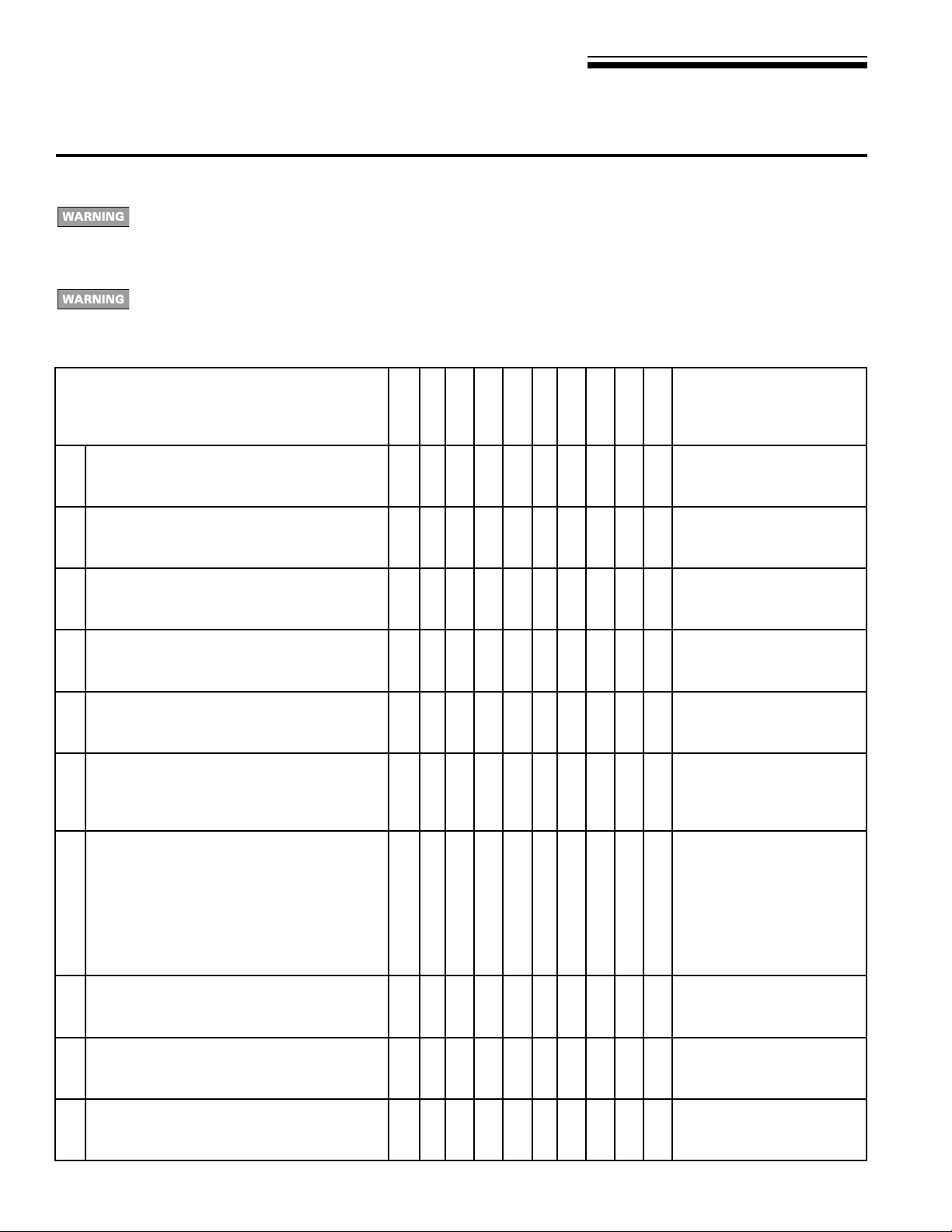
Annual service and start-up
Follow the “Service and maintenance” procedures given throughout this manual and in component literature shipped with
the boiler. Failure to perf orm the service and maintenance could result in damage to the boiler or system. F ailure to follow the
directions in this manual and component literature could result in severe personal injury, death or substantial property
damage.
The boiler should be inspected and started annually, at the beginning of the heating season, only by a qualified service
technician. In addition, the maintenance and care of the boiler designated in the tab le below , and explained on the following
pages must be performed to assure maximum boiler efficiency and reliability . F ailure to service and maintain the boiler and
system could result in equipment failure.
D
D
D
A
A
A
tsilkcehcllacecivreslaunnA
)wolebdetsilredroniwollof(
T
T
T
E
E
E
D
D
D
D
D
D
D
A
A
A
A
A
A
A
T
T
T
T
T
T
T
E
E
E
E
E
E
E stnemmoC
1
.sdiuqil
2
3
.yrassecen
4
5
.02egap
6
.).sbl.tf52-02oteuqrot
7
.elzzonegnahc-
.telnirianaelc-
.91egapeeS.syaweulfreliobnaelC
.sgnittesedortcelenoitingikcehc-
.leehwdnagnisuohrewolbnaelc-
.yleerfsnrutleehwrewolberusekam-
.deriuqerfirotomrenrublio-
elbitsubmocmorfeerfsiaerareliobtahtkcehC
dnasropavelbammalfrehtodnaenilosag,slairetam
otnoitcurtsboynaevomerdnarofkcehC
.reliobotwolfrianoitalitnevdnanoitsubmoc
roftnevroyenmihcdnagnihceerbkcehC
saecalperroriapeR.cte,egamad,snoitcurtsbo
eeS.rotalucricdnaevlavfeilernoecivresmrofreP
firiaperdnaskaelrofgnipipdnareliobkcehC
.etalpretaehsselknattaskaelrofkcehC.dnuof
TWOrof(dnuoferaskaelfiylnostunnethgiT
:dnalaunamrenrubeeS.renrubtsujdadnatcepsnI
.reniartsdnaretlifleufegnahcronaelc-
8
9
.tnempiuqetsetnoitsubmoc
.02egapeeS
01
.02
.retawhtiwdellifsirelioberusekaM
htiwsgnittesnoitsubmocyfirevdnatinutratS
egapeeS.reliobnoslortnocllafonoitarepoyfireV
18 Part Number 672 01 1005 00
Page 19

OWB & OWT
Oil-Fired Water Boilers – Boiler Manual
11 Service and maintenance continued
Cleaning boiler flueways
The boiler contains ceramic fiber and fiberglass
materials. Use care when handling these materials
per instructions on page 21 of this manual. F ailure to
comply could result in severe personal injury .
Make sure all electrical connections to boiler are
turned off and wait until boiler is warm, not hot, before
cleaning. F ailure to do so will result in severe personal
injury, death or substantial property damage.
1. Remove jacket top panel.
2. Remove flue collector hood, saving hardware for reassemb ly .
3. Shut off oil valves. Arrange drip pans under the areas of oil
piping that will be disconnected. Disconnect oil line at burner so
that you can swing open the door completely.
4. Line combustion chamber floor with newspaper to catch any
soot that will be loosened in the cleaning process.
5. Starting at the top of the boiler, use a wire flue brush to thoroughly
clean between all pins at all angles. Be careful not to damage
side walls of rear refractory .
6. Move to the bottom of the flueways and clean up between the
sections to reach pins left uncleaned in step #5.
7. Once the flueways are cleaned, carefully remove the paper
from the floor of the combustion chamber. Fold the paper to
capture the refuse, seal in a plastic bag, and dispose.
8. Verify sealing rope around flue area is intact. Visually check
condition and position of insulation in combustion chamber floor,
and the refractories at the rear of boiler and in the burner
mounting door. Replace any parts as necessary .
9. Close bur ner mounting door and tighten nut securely. Place
flue collector hood on top of boiler. Secure with hardware from
step #2. Maintain a gas-tight seal to avoid possible flue gas
leakage and carbon monoxide emissions, which can lead to
severe personal injury or death.
10. Check breeching for sooting and clean if necessary. Install
jacket top panel and breeching.
11. Reconnect oil line and all electrical connections.
Figure 16 Cleaning boiler flueways — Thoroughly clean
flueways between all pins at all angles. Start
on top of boiler, finish from the bottom.
Wear a NIOSH -certified dust respirator (N95) while
cleaning the boiler, per WARNING on page 21. Failure
to comply could result in severe personal injury.
19Part Number 672 01 1005 00
Page 20

OWB & OWT
Oil-Fired Water Boilers – Boiler Manual
11 Service and maintenance continued
Fill the system:
1. Close manual and automatic air vents and drain cock.
2. Fill to correct system pressure. Correct pressure will vary with
each installation. Normal cold water fill pressure for residential
systems is 12 psig. Boiler water pH 7.0 to 8.5 is recommended.
Failure to maintain recommended pH le vel can cause
section failure and leaks, resulting in potential of
severe personal injury , death or substantial property
damage.
3. Open automatic air vent (if installed) one turn.
4. Starting on the lowest floor, open manual air v ents one at a time
until water squirts out. Close vent. Repeat with remaining v ents.
5. Refill to correct pressure.
T o place boiler in operation:
Follow information below to prevent severe personal
injury, death or substantial property damage:
• Do not use crankcase drainings or any oil containing
gasoline. See burner manual for proper fuel oil.
• Do not attempt to start burner when excess oil has
accumulated in combustion chamber, when unit is
full of vapor, or when combustion chamber is very
hot.
• Do not start burner unless collector hood, breeching
and burner mounting door are secured in place. Never
burn garbage or paper in the boiler.
• Never leav e combustible material around boiler .
1. Verify boiler is filled with water.
2. Open burner door and verify rear target wall,floor and burner
door insulations are in proper condition and position.
3. Verify burner mounting door is closed and bolted tightly and
burner plug is connected.
4. Refer to burner manual for burner start-up, adjustment and
checkout procedures. F actory burner adjustment and settings
may not be suitable for specific job conditions.
Make final burner adjustments using combustion test
equipment to assure proper operation. Do not fire
boiler without water. Sections will ov erheat, damaging
boiler and resulting in substantial property damage.
5. Check boiler and system piping for leaks.
6. Inspect breeching and venting for proper operation.
Annual service
Boiler relief valve
1. Inspect the relief valve and lift the lever to verify flow as in the
following warnings, excerpted from a relief valve manuf acturer’s
warning label. Before operating any relief valve, ensure that it is
piped with its discharge in a safe area to avoid severe scald
potential. Read manual Section 4, page 7, before proceeding
further.
Safety relief valv es should be reinspected A T LEAST
ONCE EVERY THREE YEARS, by a licensed plumbing contractor or authorized inspection agency, to
ensure that the product has not been affected by
corrosive water conditions and to ensure that the
valve and discharge line have not been altered or
tampered with illegally. Certain naturally occurring
conditions may corrode the valve or its components
over time, rendering the valve inoperative. Such conditions are not detectable unless the valve and its
components are physically removed and inspected.
This inspection must only be conducted by a plumbing contractor or authorized inspection agency — not
by the owner . F ailure to reinspect the boiler relief valv e
as directed could result in unsafe pressure buildup ,
which can result in severe personal injury, death or
substantial property damage.
2. After following the above warning directions, if the relief valve
weeps or will not seat properly , replace the relief valve . Ensure
that the reason for relief valve weeping is the valve and not
over-pressurization of the system due to expansion tank
waterlogging or undersizing.
Following installation, the valve lever must be
operated AT LEAST ONCE A YEAR to ensure that
waterways are clear. Certain naturally occurring
mineral deposits may adhere to the valve, rendering
it inoperative. When manually operating the lever,
water will discharge and precautions must be taken
to avoid contact with hot water and to avoid water
damage. Before operating le ver , check to see that a
discharge line is connected to this valve directing the
flow of hot water from the valve to a proper place of
disposal otherwise severe personal injury may result.
If no water flows, valve is inoperative. Shut down
boiler until a new relief valve has been installed.
Oiled-bearing circulators
1. The circulator shipped with the OWB and OWT boilers are
water-lubricated. No oiling is required.
2. Check other circulators in the system. Oil any circulators
requiring oil, following circulator manufacturer’s instructions.
Over-oiling will damage the circulator .
Oiled-bearing burner motors
1. The burner may need to be lubricated if motor is equipped with
oiling cups. Apply a few drops only of SAE 20 detergent oil
(never use household oils). Do not attempt to “fill up” the oil cup.
Over-oiling can damage the motor .
Verify component operation
1. Perform the checkout sequence on page 16 to verify system
and components are operating correctly .
20 Part Number 672 01 1005 00
Page 21

OWB & OWT
Oil-Fired Water Boilers – Boiler Manual
11 Service and maintenance
continued
Handling ceramic fiber and fiberglass materials
REMOVAL OF COMBUSTION CHAMBER LINING OR BASE PANELS
The combustion chamber lining or base insulation panels in this product contain ceramic fiber materials. Ceramic
fibers can be converted to cristobalite in very high temperature applications. The International Agency for Research
on Cancer (IARC) has concluded, "Crystalline silica inhaled in the form of quartz or cristobalite from occupational
sources is carcinogenic to humans (Group 1).":
■ Avoid breathing dust and contact with skin and e yes.
• Use NIOSH certified dust respirator (N95). This type of respirator is based on the OSHA requirements f or
cristobalite at the time this document was written. Other types of respirators may be needed depending on
the job site conditions. Current NIOSH recommendations can be found on the NIOSH web site at http://
www.cdc.gov/niosh/homepage.html. NIOSH approved respirators, man ufacturers, and phone numbers are
also listed on this web site.
• Wear long-sleeved, loose fitting clothing, gloves, and eye protection.
■ Apply enough water to the combustion chamber lining or base insulation to prevent airborne dust.
■ Remove combustion chamber lining or base insulation from the boiler and place it in a plastic bag for disposal.
■ Wash potentially contaminated clothes separately from other clothing. Rinse clothes washer thoroughly .
NIOSH stated First Aid.
■ Eye: Irrigate immediately
■ Breathing: F resh air.
REMOVAL OF FIBERGLASS WOOL — OR —
INSTALLATION OF FIBERGLASS WOOL, COMBUSTION CHAMBER LINING OR BASE
PANELS:
This product contains fiberglass jacket insulation and ceramic fiber materials in combustion chamber lining or base
panels in gas fired products. Airborne fibers from these materials have been listed by the State of California as a
possible cause of cancer through inhalation.
■ Avoid breathing dust and contact with skin and e yes.
• Use NIOSH certified dust respirator (N95). This type of respirator is based on the OSHA requirements f or
fiberglass wool at the time this document was written. Other types of respirators may be needed depending
on the job site conditions. Current NIOSH recommendations can be found on the NIOSH web site at http://
www.cdc.gov/niosh/homepage.html. NIOSH approv ed respirators, manuf acturers, and phone numbers are
also listed on this web site.
• Wear long-sleeved, loose fitting clothing, gloves, and eye protection.
■ Operations such as sawing, blowing, tear out, and spraying may generate airborne fiber concentration requiring
additional protection.
■ Wash potentially contaminated clothes separately from other clothing. Rinse clothes washer thoroughly .
NIOSH stated First Aid.
■ Eye: Irrigate immediately
■ Breathing: F resh air.
21Part Number 672 01 1005 00
Page 22

OWB & OWT
Oil-Fired Water Boilers – Boiler Manual
12 Replacement parts
Figure 17 Boiler section assembly, refractories, collector hood and burner door assembly
22 Part Number 672 01 1005 00
Page 23

OWB & OWT
12 Replacement parts continued
Table 6 Parts list for Figure 17
Oil-Fired Water Boilers – Boiler Manual
Figure
number
Description Boilermodel
number
A Front section, number 7112 All 316722013WT
B Front section with tanklessheater opening, number 7113 All 316722005WT
C Intermediate section, number7115 All 316722017WT
D Back section, number 7117 All 316722021WT
E Section replacement kit, front or back section
(for 1 joint, includes seals, rope, adhesive and collector hood hardware)
Section replacement kit, intermediate section
(for 2 joints, includes seals, rope and adhesive)
Section assemblycomplete OWB3 326700020WT
F Collector hood kit
(includes rope and hardware for installation)
G Tie rod½ x10¾" OWB/OWT3 560234491WT
Tie rod ½ x14" OWB/OWT4 560234470WT
Tie rod ½ x17" OWB/OWT5 560234472WT
Tie rod ½ x20" OWB/OWT6 560234534WT
H Combustion chamber kit
(rear and front refractory, door refractory blanket andwater glass)
Burner mounting door assembly
(door, observation port, rope, insulation and pins)
J Burner mounting door, number 7171 All 330054305WT
K Door hinge, number 7054 All 330054300WT
L Door refractory All 592400028WT
M Door refractory blanket All 591222115WT
N Observation port shutter All 460039867WT
P Door seal rope 5’ All 59073-105WT
3
Q
/8" Glass rope for collectorhood (7’ forlargest size hood) All 590735109WT
R Heater cover plate carton (cover plate, gasket, studs and nuts) All 386700360WT
S Tankless heater kit (heater, gasket,studs and nuts)
OWT3 (heater model WT-11)
OWT4 through OWT6 (heater model WT-14)
Flue brush, 123D All 591706214WT
All 386700852WT
All 386700851WT
OWB4 326700021WT
OWB5 326700022WT
OWB6 326700023WT
OWT3 326700010WT
OWT4 326700011WT
OWT5 326700012WT
OWT6 326700013WT
OWB/OWT3 386700841WT
OWB/OWT4 386700842WT
OWB/OWT5 386700843WT
OWB/OWT6 386700844WT
All 386700836WT
All 343500546WT
OWT3
OWT4, 5 & 6
International Comfort Products
part number
590921599WT
590921612WT
23Part Number 672 01 1005 00
Page 24

OWB & OWT
Oil-Fired Water Boilers – Boiler Manual
12 Replacement parts continued
Figure 18 Jacket parts and replacement instructions
The boiler contains ceramic fiber and fiberglass
materials. Use care when handling these materials
per instructions on page 21 of this manual. F ailure to
comply could result in severe personal injury .
Before installing jacket:
1. Do not remove any knockouts.
2. Make sure all unused tappings are plugged.
3. These parts may be on boiler:
• Supply piping
• Return piping
• Drain valve
• Air vent or expansion tank piping
4. These parts must be off boiler:
• Breeching connection
• Pressure/temperature gauge and limit control
• Water relief valv e and piping
5. Remove burner mounting door by removing locking nut and
lifting door off hinge. Do not remove hinge.
Item
number
Descr i pti on Boiler
1 Jacket panel, front
without heateropening
with heater opening
2 Jacketpanel, leftside and
back
3 Jacket panel, top OWB/OWT3
4 Jacket panel, right side
and back
model
number
OWB (All)
OWT (All)
OWB/OWT3
OWB/OWT4
OWB/OWT5
OWB/OWT6
OWB/OWT4
OWB/OWT5
OWB/OWT6
OWB/OWT3
OWB/OWT4
OWB/OWT5
OWB/OWT6
Int ernational
Comfort
Products
partnumber
426722001WT
426722003WT
426722025WT
426722027WT
426722029WT
426722031WT
426722007WT
426722009WT
426722011WT
426722013WT
426722035WT
426722037WT
426722039WT
426722041WT
To install jacket:
1. Install jacket front panel to front section, making sure burner
door hinge lugs extend through holes in lower jacket leg. Secure
with two 3/8" x 1/2" black machine screws.
2. Right and left side pieces are shipped as straight pieces. Before
installing, bend about 90° at perforation as shown, to form sides
and back panels.
a. Secure side panels to front panel with four sheet metal
screws.
b. To secure bac k panels, using two 1/4" x 1/2" self-tapping
screws:
1) Start upper screw in boiler section. Do not tighten.
2) Slip keyhole opening in back panels behind scre w .
3) Install lower screw and tighten both screws.
c. Install top panel and secure with two sheet metal screws.
3. Reinstall burner mounting door and secure locking nut on stud,
making sure door is secured gas-tight.
Gas-tight seal must be obtained to prevent possible
flue gas leakage and carbon monoxide emissions,
leading to severe personal injury or death.
Jacket hardware kit All 386700845WT
24 Part Number 672 01 1005 00
Page 25

OWB & OWT
12 Replacement parts continued
Figure 19 Trim and controls
Oil-Fired Water Boilers – Boiler Manual
Item
number
not shown Circulator hardware kit, includes:
not shown Burner wiring harness International Comfort Products 591391911WT
not shown Burner plug International Comfort Products 643900020WT
not shown Balanced draft damper (barometric) Effikal ESOC-7 510512267WT
Description Manufacturer Manufacturer’s
1 Pressure relief valve, ASME, 30 PSIG, ¾" male inlet Watts M330 511546920WT
2 Combination high limit/circulator relay control (OWB)
Combination high limit/low limit/circulator relay control
(OWT)
3 Combination pressure-temperature gauge ENFM 4104 510218099WT
4 Circulator (Fittings shown are shipped loose with boiler.) Taco 007 511405113WT
5 Circulator gasket, universal(2 per boiler) International Comfort Products
2 flanges,4 nuts, 4 screws, 1 nipple, 1 ell —
1¼"NPT— OWB/OWT3 & OWB/OWT4
1½"NPT— OWB/OWT5 & OWB/OWT6
6 Circulator wiring harness International Comfort Products 591391910WT
7 Drain valve, ¾" Conbraco
Honeywell
Honeywell
International Comfort Products
Hammond Valve
Matco-Norca
Watts
part num ber
L8148A1157
L8124A1155
31-606-01
710
205F04
BD-2C
Internat ional
Comfort
Products
partnumber
510311030WT
510311040WT
590317535WT
381354526WT
381354531WT
511210423WT
511246392WT
511246392WT
511246392WT
25Part Number 672 01 1005 00
Page 26

OWB & OWT
Oil-Fired Water Boilers – Boiler Manual
13 Dimensions
Figure 20 Dimensional drawing — ALL DIMENSIONS IN INCHES
Boiler
model
number
Supply
tapping
(inches NPT)
Return
tapping
(inches NPT)
“B”
Combustion chamber
dept h (inches)
“D”
Jacket depth
(inches)
OWB/OWT3 1½ 1½ 10 ½ 13 ¾
OWB/OWT4 1½ 1½ 135/
OWB/OWT5 1½ 1½ 167/
OWB/OWT6 1½ 1½ 20 231/
8
8
167/
20
8
8
26 Part Number 672 01 1005 00
Page 27

14 Ratings
OWB & OWT
Oil-Fired Water Boilers – Boiler Manual
DOE
Boiler
model
number
Note 1 Note 3 Notes 2 & 4 Note 5 Note 6 Note 7
I=B=R
burner
capacity
GPH
DOE
heating
capacity
MBH
Net I=B=R
ratings
MBH
Water
sq. feet
DOE
seasonal
efficiency
%AFUE
Round
flue
outlet
size
inches
Minimu m I=B=R
Chimney
Rectangle
inches
Round
inches
Height
feet
Boiler
water
content
gallons
Draft loss
through
boiler
inches W.C.
OWB/OWT3075 0.75 90 78 84.3 7 8x8 6 15 11.0 .000
OWB/OWT3100 1.00 116 101 82.2 7 8x8 6 15 14.9 .000
OWB/OWT4110 1.10 129 112 82.5 7 8x8 6 15 13.4 .010
OWB/OWT4125 1.25 145 126 81.7 7 8x8 6 15 13.4 .010
OWB/OWT5135 1.35 159 138 82.8 7 8x8 7 15 15.9 .010
OWB/OWT5150 1.50 174 151 81.3 7 8x8 7 15 15.9 .010
OWB/OWT5165 1.65 191 166 81.2 7 8x8 7 15 15.9 .010
OWB/OWT6175 1.75 203 177 80.8 7 8x8 7 15 18.4 .000
Notes
1. See information at right for model number suffixes.
2. MBH refers to thousands of Btu per hour.
3. Base on 140,000 Btu per gallon.
4. Based on standard test procedures prescr ibed by the United States Department of
Energy , with combustion conditions of 13% CO
5. Net I=B=R ratings are based on net installed radiation of sufficient quantity for the
requirements of the building and nothing need be added for normal piping and pickup.
Ratings are based on a piping and pickup allowance of 1.15. An additional allowance
should be made for unusual piping and pickup loads.
6. See page 6 for minim um breeching diameter.
7. Listed draft losses are for factory-shipped settings.
and –0.02" W .C. draft.
2
Install OWB and OWT boilers f or residential radiant panel systems, converted
gravity heating systems or other low water temperature applications per
instructions in this manual to avoid damage due to condensation.
OWB and OWT boilers are CSA design certified for installation on combustib le
flooring.
OWB and OWT boilers are ASME rated for 50 psig working pressure.
27Part Number 672 01 1005 00
Page 28

OWB & OWT
Oil-Fired Water Boilers – Boiler Manual
28 Part Number 672 01 1005 00
 Loading...